

Page 1
MAKING MODERN LIVING POSSIBLE
Service Manual
Steering Unit
Type OSPD V2
powersolutions.danfoss.com
Page 2

Service Manual Hydrostatic Steering Unit Type OSPD V2
Revision History Table of Revisions
Date Changed Rev
Feb 2014 Torque value under assembly corrected AB
Dec 2013 First version - DITA CMS AA
2 L1310051 • Rev AB • Feb 2014
Page 3

Service Manual Hydrostatic Steering Unit Type OSPD V2
Contents
Safety Precautions
Safety Precautions............................................................................................................................................................................4
Service Literature
Symbols Used in Danfoss Literature..........................................................................................................................................5
OSPD Versions, Belonging Service Literature.........................................................................................................................5
Exploded View and Seal Kit
Exploded View, OSPD V2/OSPD New Design.........................................................................................................................6
Seal Kit for OSPD...............................................................................................................................................................................7
Tools
Tools......................................................................................................................................................................................................8
Disassembly
Disassembling OSPD V2.............................................................................................................................................................. 10
Assembly
Assembling OSPD V2....................................................................................................................................................................18
Tightening Torques
Tightening Torques for Connections OSDP V2...................................................................................................................30
L1310051 • Rev AB • Feb 2014 3
Page 4

W
W
W
W
W
Service Manual
Safety Precautions
Safety Precautions
Hydrostatic Steering Unit Type OSPD V2
Always consider safety precautions before beginning a service procedure. Protect yourself and others
from injury. Take the following general precautions whenever servicing a hydraulic system.
Warning
Unintended Machine Movement
Unintended movement of the machine or mechanism may cause injury to the technican or bystanders.
To prevent uintended movement, secure the machine or disable / disconnect the mechanism while
servicing.
Warning
Flammable Cleaning Solvents
Some cleaning solvents are flammable. To eliminate the risk of fire, do not use cleaning solvents in an
area where a source of ignition may be present.
Warning
Fluid under Pressure
Escaping hydraulic fluid under pressure can have sufficient force to penetrate your skin causing serious
injury and/or infection. This fluid may also be hot enough to cause burns. Use caution when dealing with
hydraulic fluid under pressure. Relieve pressure in the system before removing hoses, fittings, gauges, or
components. Never use your hand or any other body part to check for leaks in a pressurized line. Seek
medical attention immediately if you are cut by hydraulic fluid.
Warning
Personal Safety
Protect yourself from injury. Use proper safety equipment, including safety glasses, at all times.
Warning
Product Safety
Steering units are safety components and therefore it is extremely important that the greatest care is
taken when servicing these products. There is not much wear on a steering unit and therefore they
normally outlast the application they are built into. Therefore the only recommended service work on
steering units is:
•
Changing shaft seals and o-rings
•
Disassemble, clean and assemble if contaminated
•
Make hydraulic testing including valve setting.
4 L1310051 • Rev AB • Feb 2014
Page 5
Gear set I
39
Shifting valve
Gear set II
P301 641a
Gear set I
39
Shifting valve
Gear set II
P301 641b
Service Manual
Hydrostatic Steering Unit Type OSPD V2
Service Literature
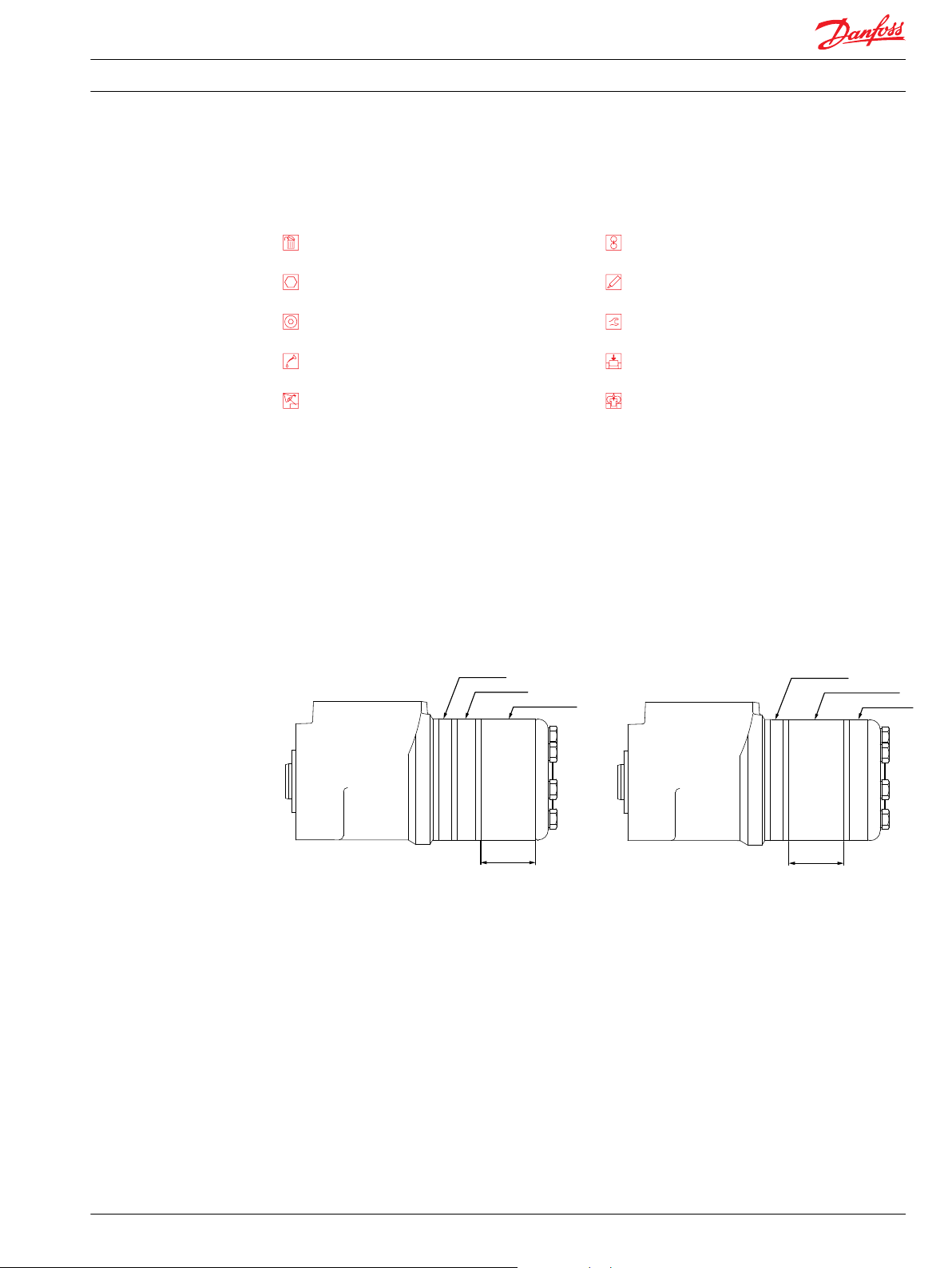
Symbols Used in Danfoss Literature
Non removable part, use a new part Note correct orientation
External hex head Mark orientation for reinstallation
Internal hex head Torque specification
Lubricate with hydraulic fluid Press in - press fit
Inspect for wear or damage Pull out with tool - press fit
OSPD Versions, Belonging Service Literature
This service literature is valid for OSPD V2/OSPD in new design only.
If the OSPD in question is in “old” or “V2/new” design can be traced by the product code:
•
OSPD’s with product code number higher than 11113069 are all in “new” design
•
OSPD’s with product code number 150xxxxx ( e.g. 150G4051) and with product code lower than
11113069 are all in “old” design
The outside shape differs between OSPD in “old” and “V2/new” design:
OSPD old design OSPD V2 / New Design
For further explanations between OSPD in “old” and “new” design, see Product Information Bulletin
ST2013-068.
Service literature HN.21.ZA.52 is valid for OSPD in “old” version.
L1310051 • Rev AB • Feb 2014 5
Page 6
16
17
13
18
16
37
1
16
18
18
17a
18
2
3
4
5
10
7
11
33
34
20
21
24
19
18
12
51
18
18
54
36
35
25
30
31
40
41
42
43
26
27
28
32
56
25
40
41
26
27
28
P301 642
22
23
Service Manual Hydrostatic Steering Unit Type OSPD V2
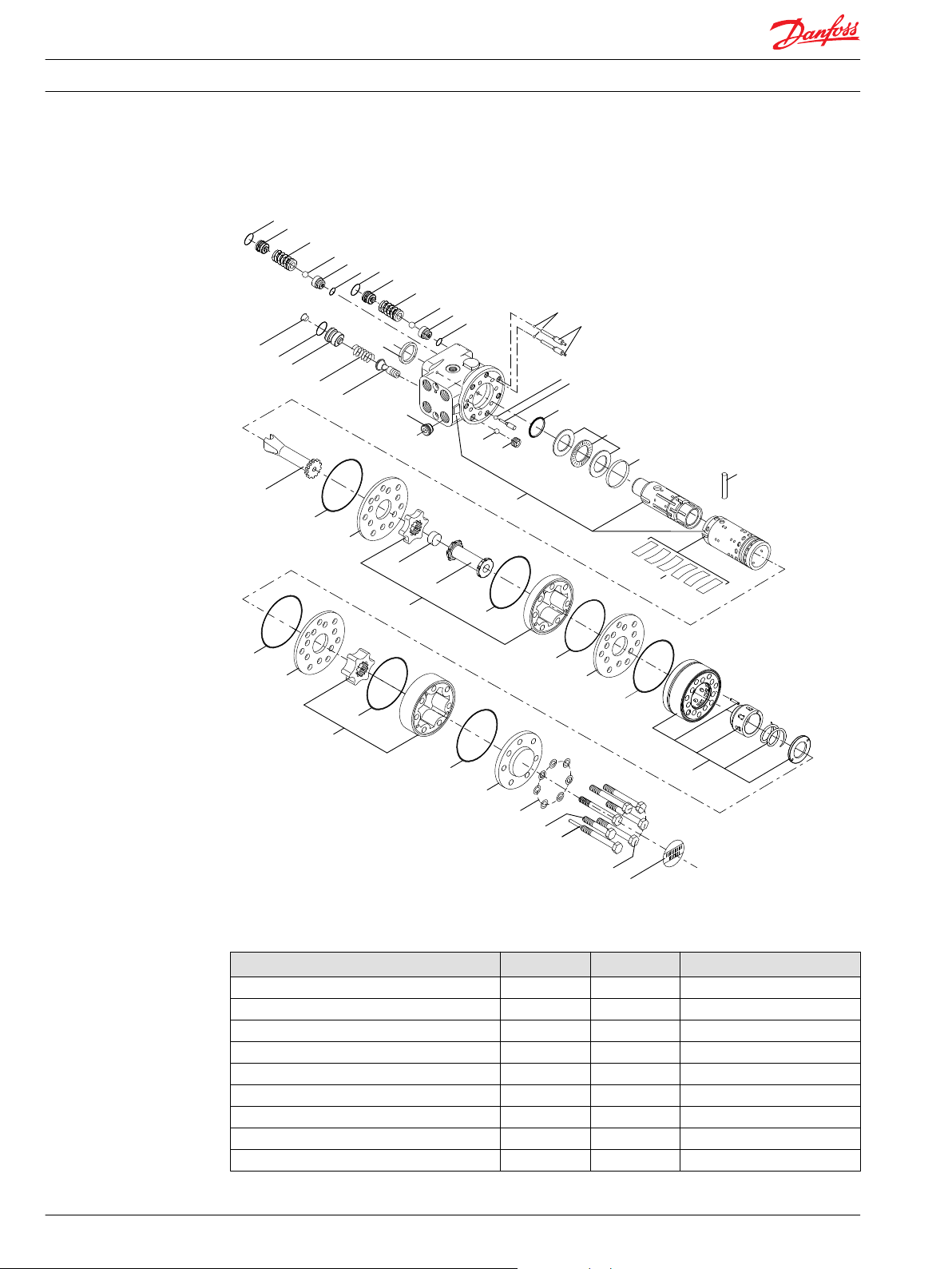
Exploded View and Seal Kit
Exploded View, OSPD V2/OSPD New Design
OSPD V2 Parts List
Parts list Num. per unit Item Tightening torque
Dust seal ring 1 1 Housing & spool/sleeve 1 2 Ball Ø8.5 mm 1 3 Threaded bushing 1 4 Screw below surface of housing
Shaft seal 1 5 Bearing assembly 1 7 Ring 1 10 Cross pin 1 11 Set of springs 1 12 -
6 L1310051 • Rev AB • Feb 2014
Page 7
Service Manual Hydrostatic Steering Unit Type OSPD V2
Exploded View and Seal Kit
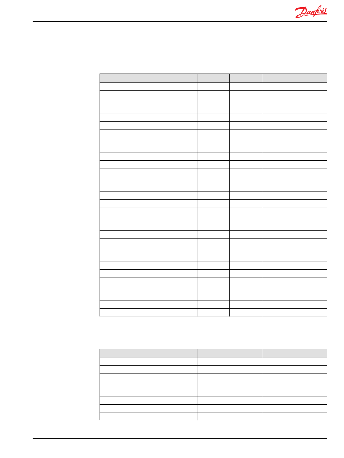
OSPD V2 Parts List (continued)
Parts list Num. per unit Item Tightening torque
Cardan shaft 1 13 Distributor plate 3 16 Gearwheel set (GWS1) 1 17 Gearwheel set (GWS2) 1 17a O-ring ø79.4 x ø2.0 mm 7 18 End cover 1 19 Washer 7 20 Screw 1 21 30±6 Nm
Pin bolt screw 1 22 30±6 Nm
Screw 5 23 30±6 Nm
Model/Code label 1 24 Adjusting screw for shock valve 2 25 Spring with thrust pad for shock valve 2 26 Ball ø3/16 in for shock valve 2 27 Seat for shock valve 2 28 6+0/-1 Nm
Adjusting screw for relief valve 1 30 Spring for relief valve 1 31 Piston for relief valve 1 32 Ball Ø3/16 in for suction valve 2 33 Bushing with pin for suction valve 2 34 Ball stop, threaded for LS check 1 35 1±0.1 Nm
Ball Ø3.0 mm for LS check 1 36 Check valve 1 37 25±5 Nm
O-ring ø9.0 x ø1.5 mm 2 40 O-ring ø6.0 x ø1.5 mm 2 41 Plug 1 42 O-ring ø14.3 x ø2.4 mm 1 43 Cardan shaft 1 51 Valve housing assembly 1 54 Do not disassembly
Spacer (present if GWS1 >/= 100 cm3) 1 56 -
Seal Kit for OSPD
Seal kit, Danfoss code 150N4041 is valid for all OSPD’s, both in “old” and in “new” design.
Parts list for 150N4041 Number per spare part kit Item
Dust seal ring 1 1
Shaft seal 1 5
O-ring 7 18
Washer 7 20
O-ring 2 40
O-ring 2 41
Plug 1 42
O-ring 1 43
L1310051 • Rev AB • Feb 2014 7
Page 8
90±1
ø46±0.5
120±2
2xø15±0.1
5±1
20±1
150±2
100±2
7x51.4°
ø64
7xø15+0.5/-0
1x45°
P301 644
0.5x45°
ø26±0.1
min ø40
min 35
100±5
P301 643
Service Manual Hydrostatic Steering Unit Type OSPD V2
Tools
Tools
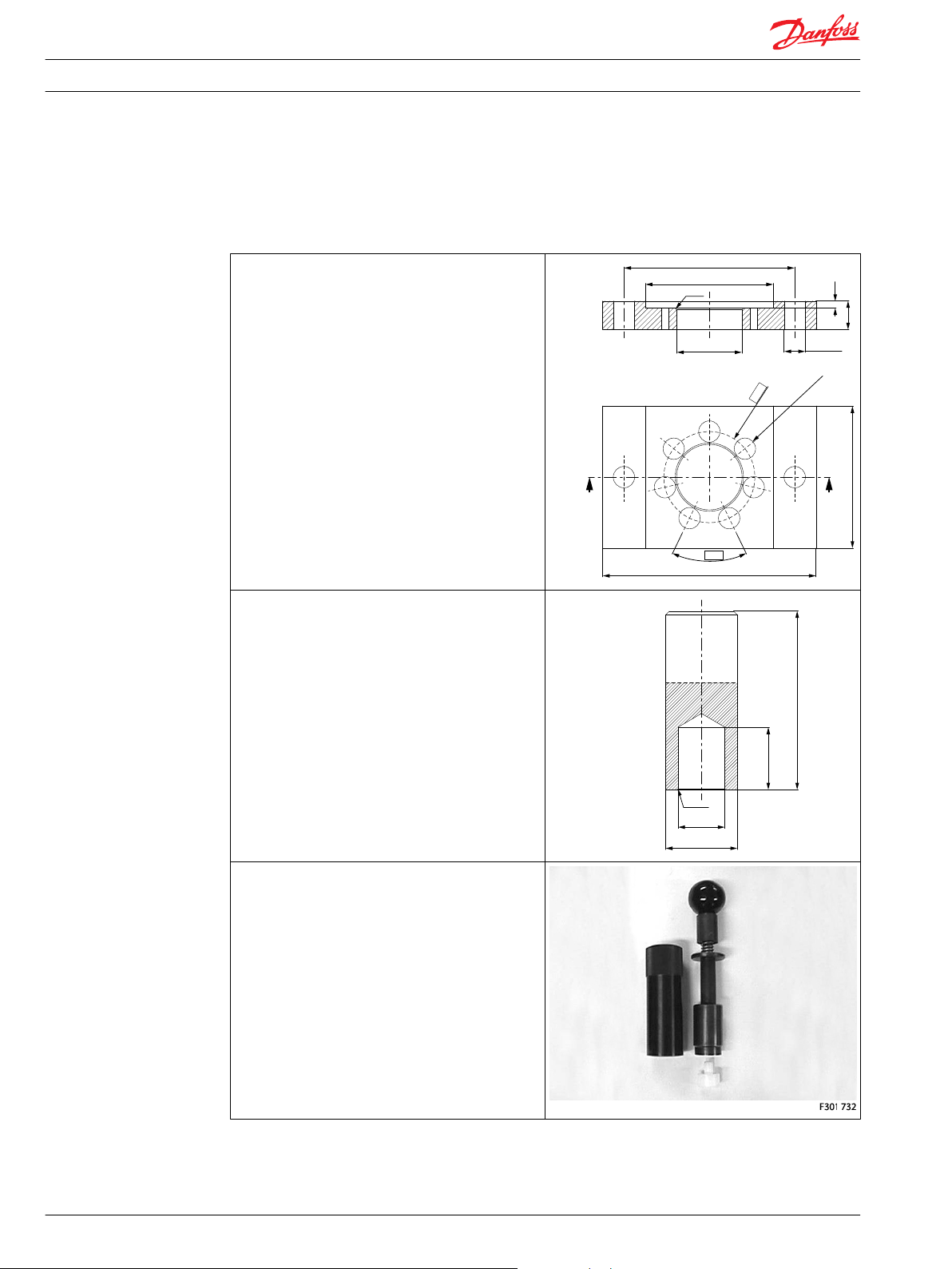
Tools
Holding tool for the entire steering unit.
Material: Appropriate metal or hard plastic.
This tool is not available from Danfoss.
Assembly tool for dust seal.
Material: Free cutting steel.
This tool is not available from Danfoss.
Assembly tool for shaft seal, O-ring/Roto Glyd type:
Code number: 11092408.
8 L1310051 • Rev AB • Feb 2014
Page 9
Service Manual Hydrostatic Steering Unit Type OSPD V2
Tools
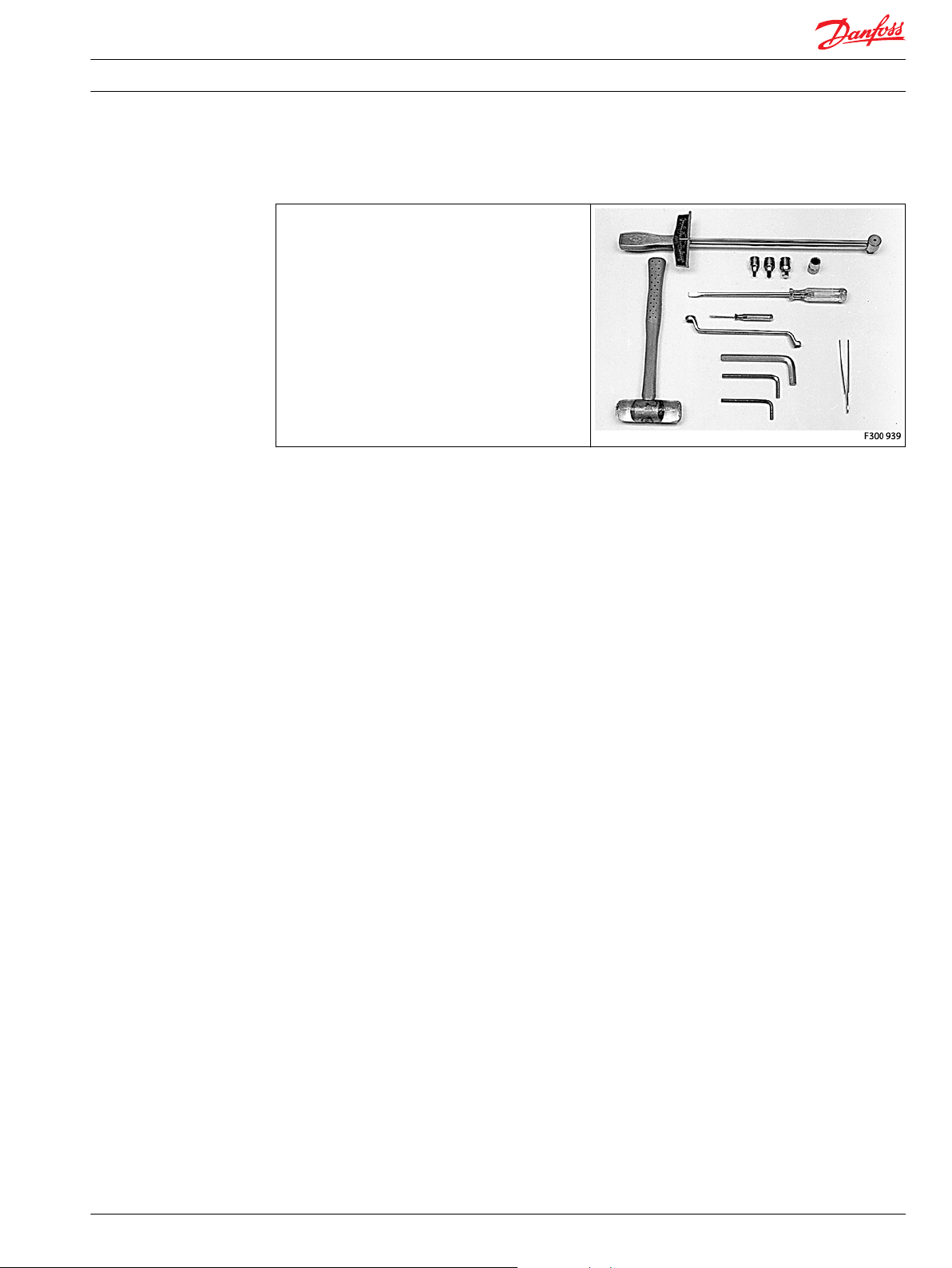
Tools (continued)
Torque wrench 0 - 70 Nm.
13 mm socket spanner.
2.75 - 5 and 6 mm Allan key.
12 mm screwdriver.
2 mm screwdriver.
13 mm ring spanner.
Plastic hammer.
Tweezers.
These tools are not available from Danfoss.
L1310051 • Rev AB • Feb 2014 9
Page 10
Service Manual Hydrostatic Steering Unit Type OSPD V2
Disassembly
Disassembling OSPD V2
Disassembly
Place the unit in the holding tool on gear set end.
Screw out the adjusting screws for shock valves (25).
O-ring (40) is fitted on adjusting screw (25).
Remove the springs with trust pads for shock valves (26).
Remove the balls for shock valves (27).
10 L1310051 • Rev AB • Feb 2014
Page 11

Service Manual Hydrostatic Steering Unit Type OSPD V2
Disassembly
Disassembly (continued)
Screw out the seats for shock valves (28).
O-ring (41) is fitted on seat (28).
Remove the plastic plug (42).
Screw out the adjusting screw for relief valve (30).
O-ring (43) is fitted on adjusting screw (30).
Remove the spring for relief valve (31).
L1310051 • Rev AB • Feb 2014 11
Page 12

Service Manual Hydrostatic Steering Unit Type OSPD V2
Disassembly
Disassembly (continued)
Remove the piston for relief valve (32).
Replace the unit in the holding tool on steering column
end.
Remove the screws (21, 22 and 23) with washers (20).
Some versions have pin bolt screw (22), threaded
bushing (4) and 5 pieces standard screws (23) as shown
on exploded view page 5. Other versions (like this taken
apart) has threaded bushing with ball stop (4) and 6
pieces standard screws (23).
All versions have one piece short standard screw (21).
Screw (21) is threaded in valve housing (54).
Remove the end cover (19), sideways.
Lift the gearwheel set (17a) off the unit.
Remove the two O-rings (18).
12 L1310051 • Rev AB • Feb 2014
Page 13

Service Manual Hydrostatic Steering Unit Type OSPD V2
Disassembly
Disassembly (continued)
Remove the rear distributor plate (16).
Remove valve housing assembly (54).
Remove the two O-rings (18).
Do not dismantle the entire valve (54)
Remove the middle distributor plate (16).
Remove the cardan shaft (51).
L1310051 • Rev AB • Feb 2014 13
Page 14

Service Manual Hydrostatic Steering Unit Type OSPD V2
Disassembly
Disassembly (continued)
Remove spacer (56) if present.
Spacer is only present in OSPD with GSW1 (17) equal to
100 cm3/rev or larger/height 13.0 mm or larger.
Lift the gearwheel set (17) off the unit. Remove the two
O-rings (18).
Remove the cardan shaft (13).
Remove the distributor plate (16) from the housing.
14 L1310051 • Rev AB • Feb 2014
Page 15

Service Manual Hydrostatic Steering Unit Type OSPD V2
Disassembly
Disassembly (continued)
Remove the threaded bushing/ball stop (4) from
housing.
Remove the ball stop (35) from housing.
Ball stop (35), and belonging ball (36) is only present in
OSPD LS with check valve in LS line.
Remove the O-ring (18) from housing.
Shake out the check valve ball (3), suction valve pins (34),
balls (33) and ball (36).
L1310051 • Rev AB • Feb 2014 15
Page 16

Service Manual Hydrostatic Steering Unit Type OSPD V2
Disassembly
Disassembly (continued)
Place the housing with the ports facing down on the
work bench. Ensure that the cross pin (11) in the spool
and sleeve set (2) is in the horizontal position.
The pin (11) can be observed through the open end of
the spool.
Press the spool (2) inwards (from the housing mounting
face end) and the sleeve (2), ring (7) and bearing
assembly (6) will be pushed out of the housing together.
Take the ring (10), bearing races and needle bearing (7)
from the spool and sleeve set (2).
The outer bearing (7) race can sometimes “stick” in the
housing, therefore check that it has come out.
Press out the cross pin (11).
Carefully press the spool out of the sleeve.
16 L1310051 • Rev AB • Feb 2014
Page 17

Service Manual Hydrostatic Steering Unit Type OSPD V2
Disassembly
Disassembly (continued)
Press the neutral position springs (12) out of the slot of
the spool.
Remove dust seal (1) and shaft seal (Roto Glyd) (5)
carefully with a screw driver or similar tool.
The steering unit OSPD is now completely dismantled
Cleaning
Clean all parts carefully in Shellsol K or similar cleaner fluid.
Inspection and Replacement
Replace all seals and washers. Check all parts carefully and make any replacements as is necessary.
L1310051 • Rev AB • Feb 2014 17
Page 18

150-386.10
150-412.10
Service Manual Hydrostatic Steering Unit Type OSPD V2
Assembly
Assembling OSPD V2
Assembling OSPD V2
Place the two flat neutral position springs in the slot.
Place the curved springs between the flat ones and press
them into place.
Configuration of spring set (12).
There can be different numbers of curved springs
depending on configuration of spring set. There can be 2,
4 or 6 curved springs.
OSPD LSR
Spool and sleeve must be positioned correctly relatively
to each other. Small marks are present on both spool and
sleeve close to one of the slots for the spring set.
Guide the spool into the sleeve (2).
If the spool and sleeve has marks as shown above, these
must be placed on same side. Make sure the centering
springs (12) are placed into the slot.
18 L1310051 • Rev AB • Feb 2014
Page 19

Service Manual Hydrostatic Steering Unit Type OSPD V2
Assembly
Assembling OSPD V2 (continued)
Line up the spring set (12).
Guide the ring (10) down over the sleeve.
The ring should be able to move free of the springs.
Fit the cross pin (11) into the spool/sleeve.
Fit bearing races and needle bearing (7) as shown on the
next drawing.
L1310051 • Rev AB • Feb 2014 19
Page 20

C
1
2
3
4
5
150-383.10
Service Manual Hydrostatic Steering Unit Type OSPD V2
Assembly
Assembling OSPD V2 (continued)
Caution
Assembly pattern for standard bearing
1. Outer bearing race
2. Needle bearing
3. Inner bearing race
4. Spool
5. Sleeve
*The inside chamfer on the inner bearing race must face
the chest of the inner spool.
Place the steering unit housing with the port face down
on the work bench. Guide the outer part of the assembly
tool into the bore for the spool/sleeve set (2).
Grease the shaft seal (Roto Glyd, 5) with hydraulic oil and
place them on the tool. Ensure that the Roto Glyd seal is
placed on the insertion tool as per the photograph.
20 L1310051 • Rev AB • Feb 2014
Page 21

Service Manual Hydrostatic Steering Unit Type OSPD V2
Assembly
Assembling OSPD V2 (continued)
Hold the outer part of the assembly tool in the bottom of
the steering unit housing and guide the inner part of the
tool right to the bottom.
Press and turn the shaft seal (5) into position in the
housing.
Draw the inner and outer parts of the assembly tool out
of the steering unit bore, leaving the guide from the
inner part in the bore.
With a light turning movement, guide the spool and
sleeve into the bore.
Fit the spool set holding the cross pin (11) horizontal.
L1310051 • Rev AB • Feb 2014 21
Page 22

Service Manual Hydrostatic Steering Unit Type OSPD V2
Assembly
Assembling OSPD V2 (continued)
The spool set will push out the assembly tool guide. The
shaft seal (5) is now installed.
Place the steering unit housing on the holding tool on
the steering column end.
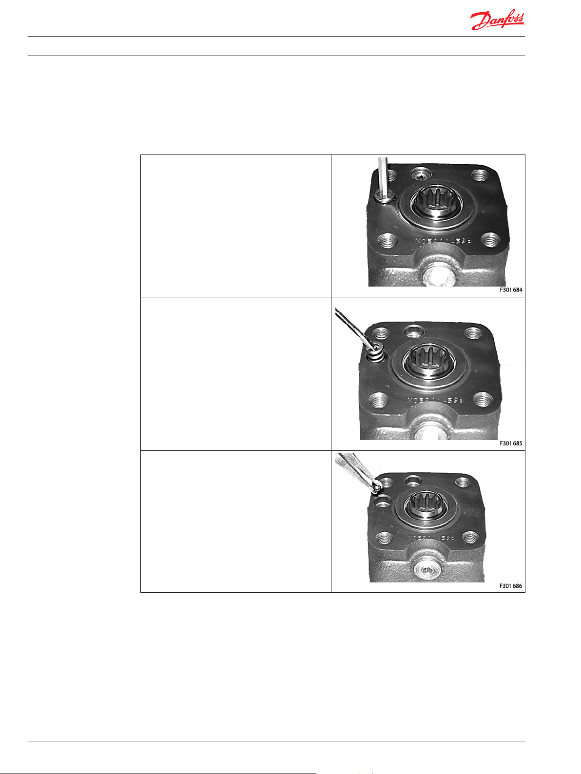
Put the check valve ball (3) into the hole indicated by the
circle.
Screw the threaded bushing/ball stop (4) lightly into the
check valve bore. The top of the bush must lie just below
the surface of the housing.
Put the check valve ball (36) into the hole indicated by
the circle.
Ball (36) is only present in OSPD LS with check valve in LS
line.
22 L1310051 • Rev AB • Feb 2014
Page 23

Service Manual Hydrostatic Steering Unit Type OSPD V2
Assembly
Assembling OSPD V2 (continued)
Screw the ball stop (35) into the LS check valve bore.
1 +/-0.1 Nm [8.85 + /- 0.885 lbf.in].
Place a ball (33) in the two bolt holes indicated by the
circles.
Place the pins (34) in the same two bolt holes.
Insert the o-ring (18) in the grove on the housing.
L1310051 • Rev AB • Feb 2014 23
Page 24

Service Manual Hydrostatic Steering Unit Type OSPD V2
Assembly
Assembling OSPD V2 (continued)
Place the distributor plate (16) so that the channel holes
match the holes in the housing.
Guide the cardan shaft (13) down into the bore so that
the slot is parallel with the connection flange ports and
lines up with the cross pin (11).
Place the 2 o-rings (18) in the two groves in the gear rim.
Fit the gearwheel and rim (17) on the cardan shaft (13).
Place the gear wheel side with all the deeper splines
facing downwards. Only this side will fit on the cardan
shaft due to all gear sets used in OSPD V2 has timing
securing: splines of gear wheel and cardan shaft can only
be assembled with correct timing.
Place the spacer (56) if present.
Spacer is only present in OSPD with GSW1 (17) equal to
or larger than 100 cm3.
24 L1310051 • Rev AB • Feb 2014
Page 25

Service Manual Hydrostatic Steering Unit Type OSPD V2
Assembly
Assembling OSPD V2 (continued)
Place and rotate the cardan shaft (51) with the big
diameter end until it moves in gear with gear wheel of
gear set (17).
Place the middle distributor plate (16) so that the channel
holes match the holes in the gear set.
Place the 2 o-rings (18) in the two groves in the valve
housing assembly (54).
Place the valve housing assembly so that the one and
only M8 thread whole points upwards and direction port
face.
Make sure that channel holes match the holes in the
distributor plate (16).
L1310051 • Rev AB • Feb 2014 25
Page 26

Service Manual Hydrostatic Steering Unit Type OSPD V2
Assembly
Assembling OSPD V2 (continued)
Place the rear distributor plate (16) so that the channel
holes match the holes in valve housing assembly (54).
Place the 2 o-rings (18) in the two groves in the gear rim.
Fit the gearwheel and rim (17a) on the cardan shaft (51).
Place the gear wheel side with all the deeper splines
facing downwards. Only this side will fit on the cardan
shaft due to all gear sets used in OSPD V2 has timing
securing: splines of gear wheel and cardan shaft can only
be assembled with correct timing.
Place the end cover (19) in position. Ensure that the bar
codes and writing are parallel with port face.
Fit the short screw (22) with new washer (20) and place it
in the hole shown.
26 L1310051 • Rev AB • Feb 2014
Page 27

Service Manual Hydrostatic Steering Unit Type OSPD V2
Assembly
Assembling OSPD V2 (continued)
Fit the six screws (23) with new washers (20) and insert
them. In case the unit has pin bolt screw, this must be
inserted where the circle is marked: Cross-tighten all the
screws (22 and 23) with a torque of 30 +/-6 Nm [265.5
+/- 53 lbf•in].
Replace the unit in the holding tool on gear set end.
The OSPD V2 can now be function tested manually: it
must be possible to rotate input shaft with torque < 3.5
Nm [31.0 lbf•in].
Install the piston (32) to housing.
Install the spring (31) on top of the piston (32).
Place o-ring (43) on adjusting screw (30). Screw in the
adjustment screw (30) with a 6 mm Allan key. Make the
pressure setting on a test panel according to valve
setting specification.
Insert plastic protection plug (42) to the adjustment
screw (30).
L1310051 • Rev AB • Feb 2014 27
Page 28

Service Manual Hydrostatic Steering Unit Type OSPD V2
Assembly
Assembling OSPD V2 (continued)
Place o-ring (41) on the shock valve seats (28). Screw in
the seats (28) with a 2.75 mm Allan key into the cavities
indicated by the circles.
Torque 6 +/-1 Nm [53.1 +/- 8.85 lbf•in].
Place one ball (27) in each of the shock valve cavities.
Place springs with trust pads (26) over the two balls.
Place o-rings (40) on adjusting screws (25).
Screw in the two adjusting screws (25) using a 5 mm
Allan key.
Make the pressure setting on a test panel according to
valve setting specification.
Make test for external leakage:
28 L1310051 • Rev AB • Feb 2014
Page 29

Service Manual Hydrostatic Steering Unit Type OSPD V2
Assembly
Assembling OSPD V2 (continued)
Plug all ports, established 35 bar, hydraulic pressure on T
and check the unit is completely leak free.
Place the dust seal ring (1) in the housing.
Fit the dust seal ring in the housing using special tool for
dust seal assembly and a plastic hammer.
Screw in the plastic plugs into the connection ports to
keep the ports clean during storage and transportation.
L1310051 • Rev AB • Feb 2014 29
Page 30

Service Manual Hydrostatic Steering Unit Type OSPD V2
Tightening Torques
Tightening Torques for Connections OSDP V2
Tightening Torques for Connections OSPD V2
Connections Max. tightening torque Nm [lbf.in]
With cutting edge With copper washer With alum. Washer O-ring
G 1/4 35 [309] 35 [309] 35 [309] G 3/8 70 [619] 45 [398] 50 [442] G 1/2 100 [885] 55 [486] 80 [708] G 3/4 180 [1593] 90 [796] 130 [1150] 7/16-20 UNF - - - 20 [177]
3/4-16 UNF - - - 60 [531]
7/8-14 UNF - - - 90 [796]
1 1/16-12 UNF - - - 120 [1062]
M12 • 1.5 30 [265] 20 [177] 30 [265] 25 [221]
M18 • 1.5 80 [708] 55 [486] 70 [619] 50 [442]
M22 • 1.5 100 [885] 65 [575] 80 [708] 60 [531]
9/16 - 18 UNF, ORFS - - - 25 [221]
1 1/16 - 16 UN, ORFS - - - 27 [239]
30 L1310051 • Rev AB • Feb 2014
Page 31

Service Manual Hydrostatic Steering Unit Type OSPD V2
L1310051 • Rev AB • Feb 2014 31
Page 32

Danfoss Power Solutions is a global manufacturer and supplier of high-quality hydraulic and
electronic components. We specialize in providing state-of-the-art technology and solutions that
excel in the harsh operating conditions of the mobile off -highway market. Building on our extensive
applications expertise, we work closely with our customers to ensure exceptional performance for a
broad range of off -highway vehicles.
We help OEMs around the world speed up system development, reduce costs and bring vehicles to
market faster.
Danfoss – Your Strongest Partner in Mobile Hydraulics.
Go to www.powersolutions.danfoss.com for further product information.
Wherever off -highway vehicles are at work, so is Danfoss.
We off er expert worldwide support for our customers, ensuring the best possible solutions for
outstanding performance. And with an extensive network of Global Service Partners, we also provide
comprehensive global service for all of our components.
Please contact the Danfoss Power Solution representative nearest you.
Danfoss
Power Solutions GmbH & Co. OHG
Krokamp 35
D-24539 Neumünster, Germany
Phone: +49 4321 871 0
Danfoss
Power Solutions ApS
Nordborgvej 81
DK-6430 Nordborg, Denmark
Phone: +45 7488 2222
Danfoss
Power Solutions US Company
2800 East 13th Street
Ames, IA 50010, USA
Phone: +1 515 239 6000
Danfoss
Power Solutions
(Shanghai) Co. Ltd.
Building #22, No. 1000 Jin Hai Rd
Jin Qiao, Pudong New District
Shanghai, China 201206
Phone: +86 21 3418 5200
Products we off er:
• Bent Axis Motors
• Closed Circuit Axial Piston
Pumps and Motors
• Displays
• Electrohydraulic Power
Steering
• Electrohydraulics
• Hydraulic Power Steering
• Integrated Systems
• Joysticks and Control
Handles
• Microcontrollers and
Software
• Open Circuit Axial Piston
Pumps
• Orbital Motors
• PLUS+1® GUIDE
• Proportional Valves
• Sensors
• Steering
• Transit Mixer Drives
Comatrol
www.comatrol.com
Schwarzmüller-Inverter
www.schwarzmuellerinverter.com
Turolla
www.turollaocg.com
Valmova
www.valmova.com
Hydro-Gear
www.hydro-gear.com
Daikin-Sauer-Danfoss
www.daikin-sauer-danfoss.com
Local address:
Danfoss can accept no responsibility for possible errors in catalogues, brochures and other printed material. Danfoss reserves the right to alter its products without notice. This also applies to
products already on order provided that such alterations can be made without subsequential changes being necessary in specifications already agreed.
All trademarks in this material are property of the respective companies. Danfoss and the Danfoss logotype are trademarks of Danfoss A/S. All rights reserved.
L1310051 • Rev AB • Feb 2014 www.danfoss.com
©
Danfoss A/S, 2013
 Loading...