

Page 1
Technical Information
Load Sensing Steering Units
OSPB/C/F/D/L LS, OLS Priority Valves,
OSQ Flow Amplifiers
www.danfoss.com
Page 2
Technical Information
OSPB/C/F/D/L LS Steering Units, OLS Priority Valves, OSQ Flow Amplifiers
Revision history Table of revisions
Date Changed Rev
April 2021 Changed document number from 'BC00000009' and '11007611' to 'BC152886483962' 1003
October 2019 Data and image revisions throughout 0901
August 2018 Fixed typo, and updated OLS 160 dimension drawing. 0801
June 2017 Overview regarding steering components; Literature reference table: Technical data
chapter; Port thread versions; Dimensions for OSPC/OSPF 230; Specification table for non
catalogue numbers of Danfoss Priority Valves; and Flow and pressure table
July 2016 Updated text under OSPD LS: Steering unit load sensing dynamic with 2 rotary meters and
with integrated valve functions
April 2016 Updated to Engineering Tomorrow design 0503
February 2016 Update image OSPC LS/LSR and OSPF LS for OLS, OSPCX LS for OSQ 0502
September 2014 Various updates EA
February 2014 Converted to Danfoss layout - DITA CMS DA
August 2013 OSPQ deleted CA
November 2009 Steering column deleted BA
May 2006 First version AA
0701
0601
2 | © Danfoss | April 2021 BC152886483962en-001003
Page 3

Technical Information
OSPB/C/F/D/L LS Steering Units, OLS Priority Valves, OSQ Flow Amplifiers
Contents
A wide range of steering components
Conversion factors........................................................................................................................................................................... 6
Survey of literature on Danfoss steering components.......................................................................................................6
LS Steering Units OSPB, OSPC, OSPF, OSPD, OSPL
Versions................................................................................................................................................................................................7
OSPB LS: Steering unit with no valve functions...............................................................................................................8
OSPC LS: Steering unit load sensing with integrated valve functions for in line priority valve OLS............ 9
OSPC LS: Steering unit load sensing with integrated valve functions for flange on priority valve
OLSA.........................................................................................................................................................................................9
OSPC LSR: Steering unit load sensing dynamic with integrated valve functions............................................. 10
OSPF LS : Steering unit full drain load sensing dynamic and with integrated valve functions....................10
OSPD LS: Steering unit load sensing dynamic with 2 rotary meters and with integrated valve
functions.............................................................................................................................................................................. 11
OSPL LS:........................................................................................................................................................................................12
OSPBX LS, OSPCX LS and OSPLX LS: Steering units load sensing for flow amplifiers......................................14
Code numbers and weights.......................................................................................................................................................15
OSPB load sensing static non-reaction steering units................................................................................................ 15
OSPB load sensing dynamic non-reaction steering units..........................................................................................15
OSPC load sensing static non-reaction steering unit.................................................................................................. 16
OSPC load sensing dynamic non-reaction steering units..........................................................................................16
OSPC load sensing dynamic reaction steering units................................................................................................... 17
OSPF load sensing dynamic non-reaction steering units..........................................................................................17
OSPD load sensing non-reaction steering units............................................................................................................18
OSPL load sensing static non-reaction steering units.................................................................................................19
OSPL load sensing dynamic non-reaction steering units.......................................................................................... 19
OSPBX and OSPLX load sensing static steering units for OSQ static..................................................................... 20
OSPCX load sensing dynamic steering units for OSQ dynamic...............................................................................20
Specification table for non catalogue numbers of LS Steering Units......................................................................... 21
Technical data................................................................................................................................................................................. 22
Displacement, flow and pressure: OSPB LS, OSPC LS, OSPC LSR.............................................................................22
Displacement, flow and pressure: OSPF LS.....................................................................................................................24
Displacement, flow and pressure: OSPD LS.................................................................................................................... 24
Displacement, flow and pressure: OSPL LS, OSPBX LS, OSPCX LS, OSPLX LS..................................................... 25
Valve functions in OSPC, OSPF, OSPD and OSPL LS steering units..............................................................................26
Pilot pressure relief valve; (P - T, Qp) characteristic......................................................................................................26
Shock valves............................................................................................................................................................................... 26
Suction valves............................................................................................................................................................................ 26
Check valves............................................................................................................................................................................... 27
Port thread versions for OSPB LS, OSPC LS/LSR, OSPF LS, OSPD LS/LSR, OSPL LS, OSPBX LS, OSPCX
LS, OSPLX LS.............................................................................................................................................................................28
Dimensions.......................................................................................................................................................................................31
OSPB LS for OLS, OSPBX LS for OSQ...................................................................................................................................31
OSPC LS/LSR and OSPF LS for OLS, OSPCX LS for OSQ............................................................................................... 33
OSPD LS/LSR for OLS............................................................................................................................................................... 35
OSPL LS for OLS and OSPLX LS for OSQ............................................................................................................................36
OSPL 1200 LS for OLS..............................................................................................................................................................38
Valve Block OVPL
Versions............................................................................................................................................................................................. 39
Code numbers and weight.........................................................................................................................................................40
Technical data................................................................................................................................................................................. 43
Common data............................................................................................................................................................................43
Valve functions................................................................................................................................................................................43
Shock valves............................................................................................................................................................................... 44
Suction valves............................................................................................................................................................................ 44
Check valve.................................................................................................................................................................................44
Backpressure valve...................................................................................................................................................................45
Installation........................................................................................................................................................................................46
Dimensions.......................................................................................................................................................................................46
©
Danfoss | April 2021 BC152886483962en-001003 | 3
Page 4

Technical Information
OSPB/C/F/D/L LS Steering Units, OLS Priority Valves, OSQ Flow Amplifiers
Contents
Angle Block OVR
Version............................................................................................................................................................................................... 48
Code numbers and weight.........................................................................................................................................................48
Installation........................................................................................................................................................................................48
Dimensions.......................................................................................................................................................................................49
Priority Valves OLSA, OLS, and OLSP
Versions............................................................................................................................................................................................. 50
OLSA 40/80................................................................................................................................................................................. 51
OLS 40/80 and OLS 120.......................................................................................................................................................... 52
OLS 160.........................................................................................................................................................................................53
OLSP 80........................................................................................................................................................................................ 54
OLS 320.........................................................................................................................................................................................55
OLS 320 without pilot pressure relief valve.................................................................................................................... 56
System sizing...................................................................................................................................................................................57
Code numbers and weights.......................................................................................................................................................57
OLS/OLSA static priority valves for load sensing static steering units.................................................................. 57
OLS/OLSA static priority valves for load sensing statics steering units................................................................ 58
OLS/OLSA dynamic priority valves for load sensing dynamic steering units.....................................................58
OLS/OLSA dynamic priority valves for load sensing dynamic steering units.....................................................59
OLS dynamic priority valves for OSPF LS and OSPU LS dynamic steering units................................................60
Specification table for non catalogue numbers of Danfoss Priority Valves..............................................................62
Technical data................................................................................................................................................................................. 63
Max. pressure on connections............................................................................................................................................. 63
Pressure drop in priority valves........................................................................................................................................... 63
Pressure drop P-EF for static priority valves....................................................................................................................63
Pressure drop P-EF for dynamic priority valves............................................................................................................. 65
Pressure drop P-EF for OLSP static priority valves........................................................................................................ 67
Pressure drop P-EF for OLSP dynamic priority valves..................................................................................................68
Pressure drop P-EF for OLS 320 static priority valves.................................................................................................. 68
Pressure drop P-EF for OLS 320 dynamic priority valves............................................................................................69
OLS 160 and OLS 320, pilot pressure relief valve (P - T, Qp) characteristics........................................................69
Dimensions.......................................................................................................................................................................................71
OLSA..............................................................................................................................................................................................71
OLS 40, OLS 80...........................................................................................................................................................................73
OLS 120.........................................................................................................................................................................................75
OLS 160.........................................................................................................................................................................................76
OLSP 80........................................................................................................................................................................................ 77
OLS 320 in-line...........................................................................................................................................................................78
Flow Amplifiers OSQA and OSQB
Versions............................................................................................................................................................................................. 79
OSQA and OSQB static............................................................................................................................................................79
Code numbers and weights.......................................................................................................................................................80
OSQA and OSQB static flow amplifiers for load sensing static steering units....................................................80
Specification table for non catalogue numbers of Danfoss Flow Amplifier.............................................................81
Technical data................................................................................................................................................................................. 82
Flow and pressure.................................................................................................................................................................... 82
Total displacement of Steering System............................................................................................................................82
Installation...................................................................................................................................................................................82
Valve functions in the flow amplifiers...............................................................................................................................82
Priority valve...............................................................................................................................................................................82
OSQ pilot pressure relief valve (HP - HT, Qp) characteristic...................................................................................... 83
Back pressure valve..................................................................................................................................................................84
Shock valves............................................................................................................................................................................... 85
Suction valves............................................................................................................................................................................ 85
Dimensions.......................................................................................................................................................................................86
OSQA.............................................................................................................................................................................................86
OSQB............................................................................................................................................................................................. 88
4 | © Danfoss | April 2021 BC152886483962en-001003
Page 5
Technical Information
OSPB/C/F/D/L LS Steering Units, OLS Priority Valves, OSQ Flow Amplifiers
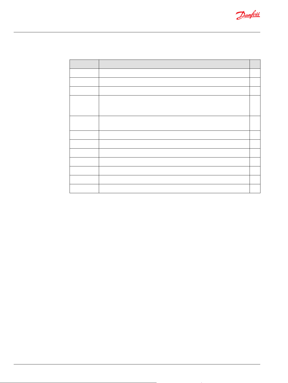
A wide range of steering components
Danfoss is one of the largest producers in the world of steering components for hydrostatic steering
systems on off-road vehicles. Danfoss offers steering solutions both at component and system levels. Our
product range makes it possible to cover applications of all types, ranging from ordinary 2 wheel steering
(also known as Ackermann steering) to articulated steering, automatic steering (for example, by sensor)
and remote controlled steering via satellite. We can offer more than 1,800 different steering units and 250
different priority valves categorized in types, variants and sizes.
Danfoss offers:
For hydrostatic steering systems:
Product type Displacement Rated Flow Steering Pressure
Mini steering units
Steering units
Priority valves
Pilot operated flowamplifiers (factors: 4, 5, 8,
or 10)
Pilot operated steering
valves
32 – 100 cm3/rev
[1.95 – 6.10 in3/rev]
40 – 1200 cm3/rev
[2.44 to 73.2 in3/rev]
–
– 240 and 400 l/min [63.4 and
–
max. 20 l/min
[5.28 US gal/min]
max. 100 l/min
[26.4 US gal/min]
40, 80, 120, 160, 320 l/min
[10.6, 21.1, 31.7, 42.3, 84.5
US gal/min]
105.7 US gal/min]
max. 100 l/min
[26.4 US gal/min]
max. 150 bar
[2180 psi]
max. 240 bar
[3481 psi]
max. 350 bar
[5076 psi]
max. 240 bar
[3480 psi]
max. 250 bar
[3625 psi]
For electrohydraulic steering systems
Product type Displacement Rated flow Steering pressure
Pilot operated steering
valves
Integrated electrical
operated steering valve
Electrical operated
steering valve
- 100 l/min [26.4 US gal/min] 250 bar [3625 psi]
100 - 500 cm3/rev
[6.10 - 30.51 in3]
- 70 l/min [18.5 US gal/min] 210 bar [3045 psi]
50 l/min [13.2 US gal/min] 210 bar [3045 psi]
©
Danfoss | April 2021 BC152886483962en-001003 | 5
Page 6

Technical Information
OSPB/C/F/D/L LS Steering Units, OLS Priority Valves, OSQ Flow Amplifiers
A wide range of steering components
Characteristic features for steering units:
Low steering torque: from 0.5 to 3 N•m in normal steering situations
•
Low noise level
•
Low pressure drop
•
Many types available: Open center Non-reaction, Open center Reaction, Power Beyond, Closed center
•
Non-reaction, Load Sensing, Load Sensing Reaction
One or more built-in valve functions: relief valve, shock valves, suction valves, non-return valve in P-
•
line and LS-line
Optional port connections according to ISO, SAE or DIN standards
•
Characteristics for EH steering systems with OSPE, EHPS, and EHi:
Possibility of GPS, row sensor, variable steering ratio and joystick steering
•
Possibility of manual steering even on very heavy vehicles
•
EHPS:
•
High steering pressure requiring smaller cylinders and flow
‒
Low pilot pressure and flow giving extremely low noise in the cabin
‒
Combined with Danfoss PVG 32 proportional valve
‒
Conversion factors
1 N•m = [8.851 lbf•in] 1 l = [0.264 US gal]
1 N = [0.2248 lbf] 1 bar = [14.5 psi]
1 mm = [0.0394 in] °F = [1.8°C + 32]
1 cm3 = [0.061 in3]
Survey of literature on Danfoss steering components
Detailed data on all Danfoss steering components and accessories can be found in our steering
component catalogs, which is divided in to the following individual sub catalogs:
General information Steering components
Technical data on mini steering units OSPM
Technical data on open center, and closed center
steering units
Technical data on load sensing steering units, priority
valves and flow amplifiers
Technical data on load sensing steering unit with
amplification
Technical data on hydraulic and EH pilot operated
steering valves, electrical actuation modules and
appropriate steering units.
Technical data on combined steering unit/EH steering
valves and steering wheel sensors
Technical data on electrohydraulic steering valves EHi
Technical data on steering wheel sensors SASA
OSPB, OSPC, and OSPD
OSPB, OSPC, OSPF, OSPD, OSPL, OSPBX, OSPLX, OVPL,
OLS and OSQ
OSPU
EHPS, EHPS w. OLS 320, PVE for EHPS and OSPCX
OSPE
For technical information on individual variants, please contact the Danfoss Sales Organization.
6 | © Danfoss | April 2021 BC152886483962en-001003
Page 7

Technical Information
OSPB/C/F/D/L LS Steering Units, OLS Priority Valves, OSQ Flow Amplifiers
LS Steering Units OSPB, OSPC, OSPF, OSPD, OSPL
Versions
Load sensing
In load sensing steering systems both the steering system and the working hydraulics can be supplied
with oil from the same pump, using a load sensing pump, also delivers the potential for energy saving.
Load sensing steering units have an extra connection for load sensing (LS), so that a load pressure signal
can be directed via the steering unit to a Danfoss priority valve and/or an LS pump. The load sensing
signal controls the oil flow from the priority valve (and/or the LS pump) to the steering unit. The LS
connection is open to tank when the steering unit is in the neutral position.
Load sensing static
Load sensing static steering units require load sensing static priority valves and/or load sensing static
variable displacement pumps. Load sensing static steering systems have no oil flow in the LS connection
when the steering unit is in neutral position.
Load sensing dynamic
Load sensing dynamic steering units require load sensing dynamic priority valves and/or load sensing
dynamic variable displacement pumps. Load sensing dynamic steering systems have a constant oil flow
in the LS connection in the direction of the steering unit even when the steering unit is in neutral
position.
Reaction
With reaction steering units any external forces acting on the steered wheels result in a corresponding
movement of the steering wheel when the driver is not steering the vehicle.
Non-reaction
With non-reaction steering units there is no corresponding movement of the steering wheel when the
driver is not steering the vehicle
©
Danfoss | April 2021 BC152886483962en-001003 | 7
Page 8
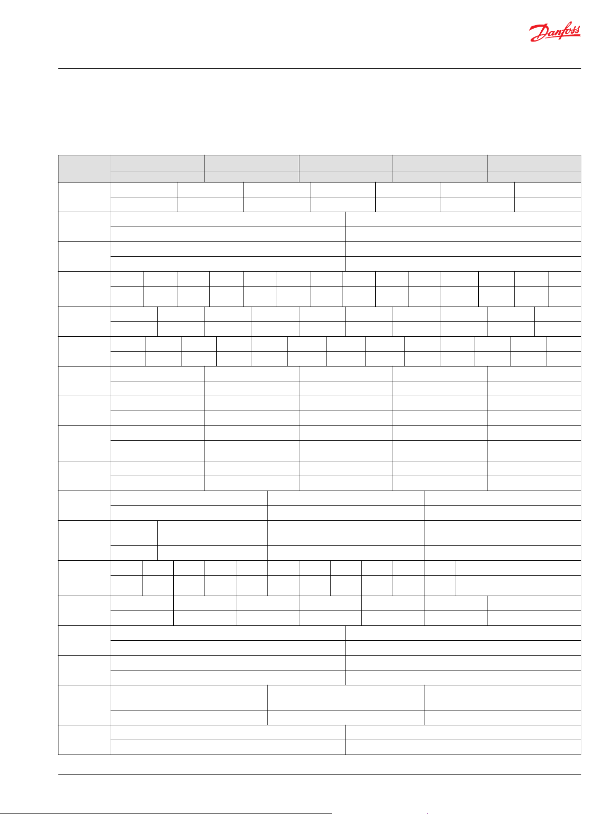
150-301.11
L
L
R
R
P
P
T
TLSLS
Technical Information
OSPB/C/F/D/L LS Steering Units, OLS Priority Valves, OSQ Flow Amplifiers
LS Steering Units OSPB, OSPC, OSPF, OSPD, OSPL
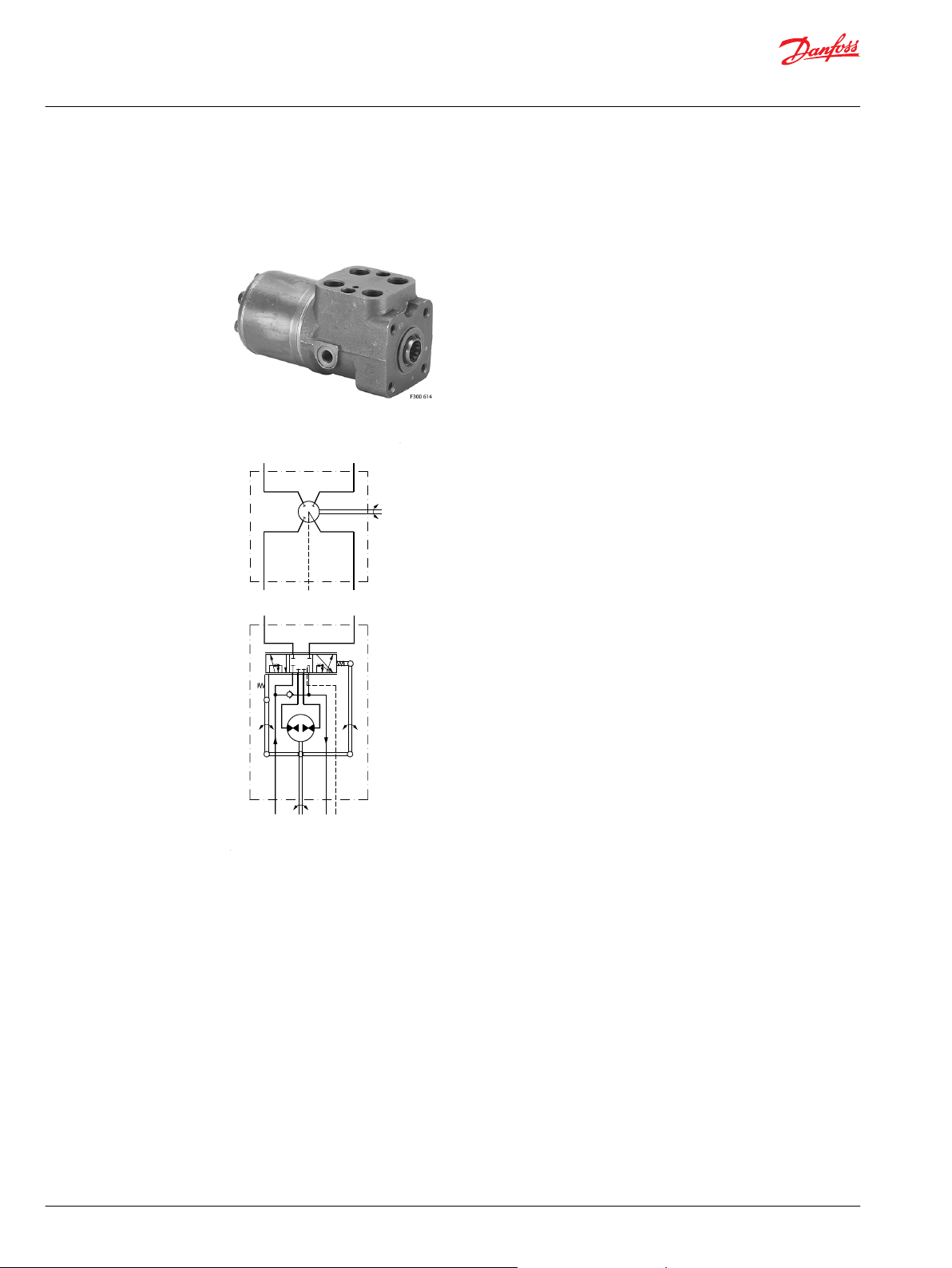
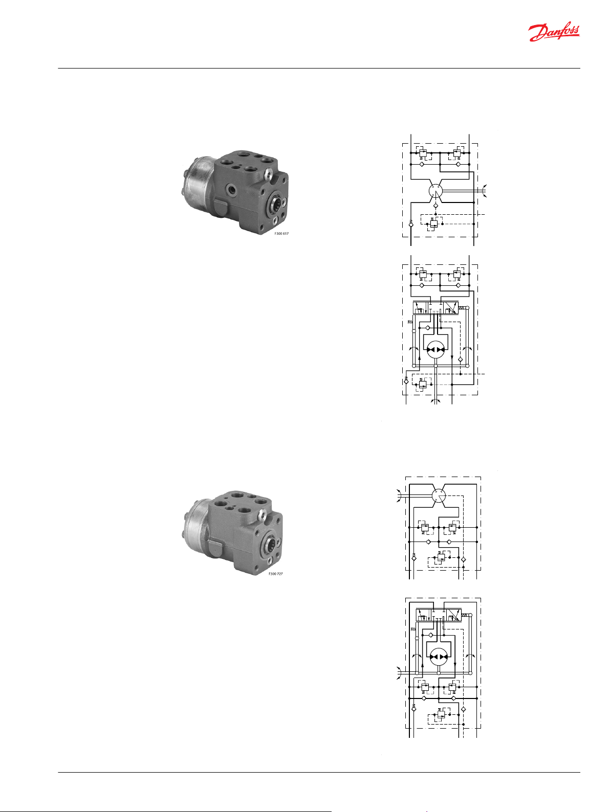
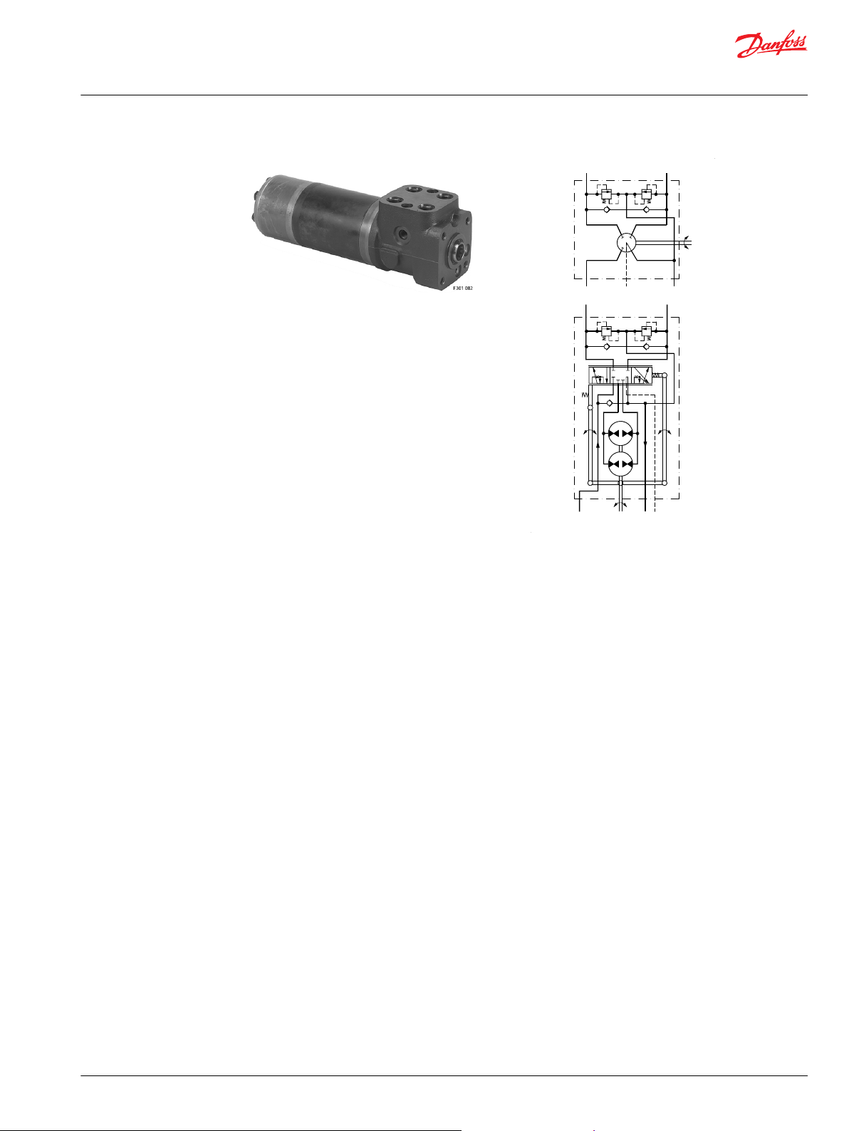
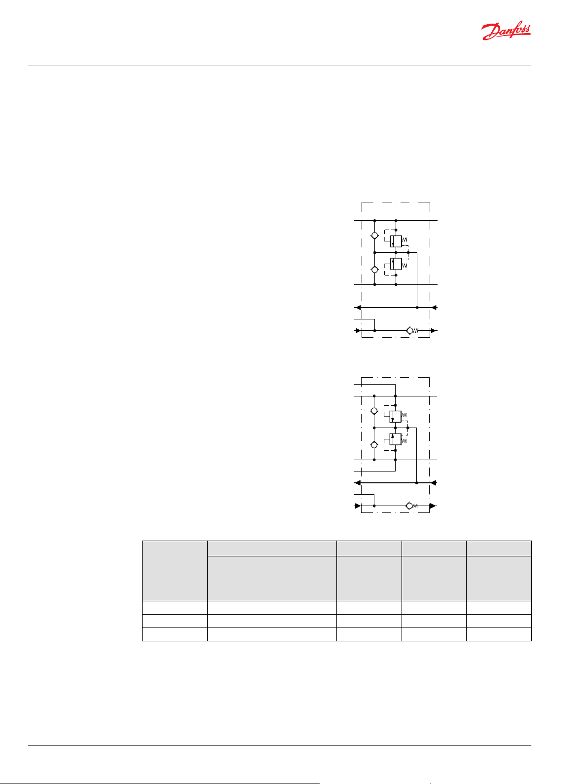
OSPB LS: Steering unit with no valve functions
OSPB LS (OLS)
Load sensing static non-reaction and load sensing dynamic non-reaction
Top: Danfoss diagram; bottom: CETOP diagram
8 | © Danfoss | April 2021 BC152886483962en-001003
Page 9
150-595.11
L
L
R
R
P
P
T
T
LS
LS
150-596.10
L
L R
R
P
P
T
TLSLS
Technical Information
OSPB/C/F/D/L LS Steering Units, OLS Priority Valves, OSQ Flow Amplifiers
LS Steering Units OSPB, OSPC, OSPF, OSPD, OSPL
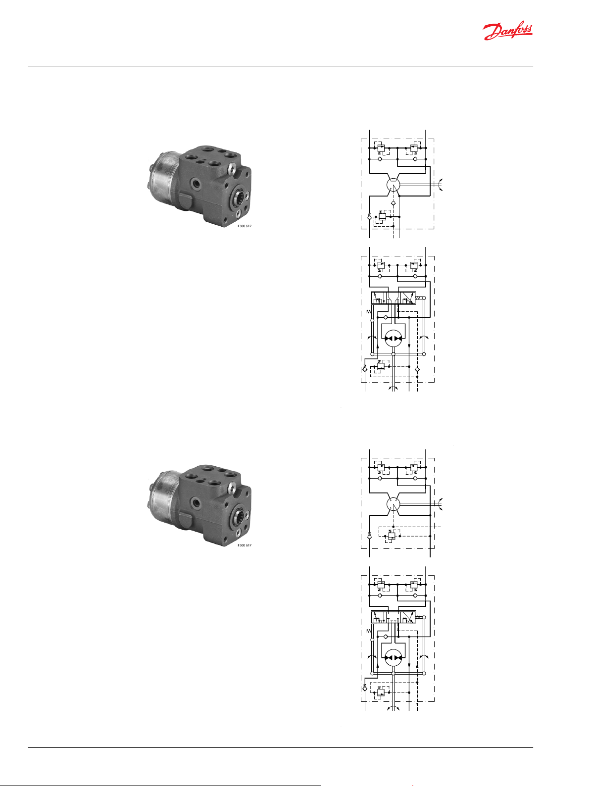
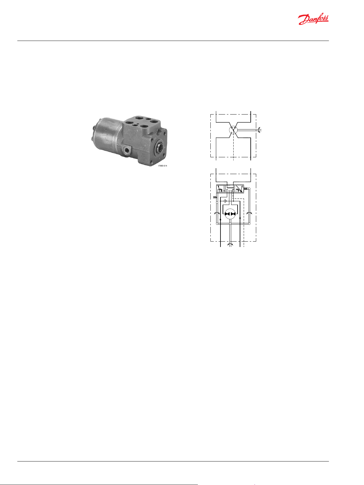
OSPC LS: Steering unit load sensing with integrated valve functions for in line priority valve OLS
OSPC LS (OLS)
Load sensing dynamic non-reaction
OSPC LS: Steering unit load sensing with integrated valve functions for flange on priority valve OLSA
OSPC LS (OLSA)
Load sensing dynamic non-reaction
©
Danfoss | April 2021 BC152886483962en-001003 | 9
Page 10
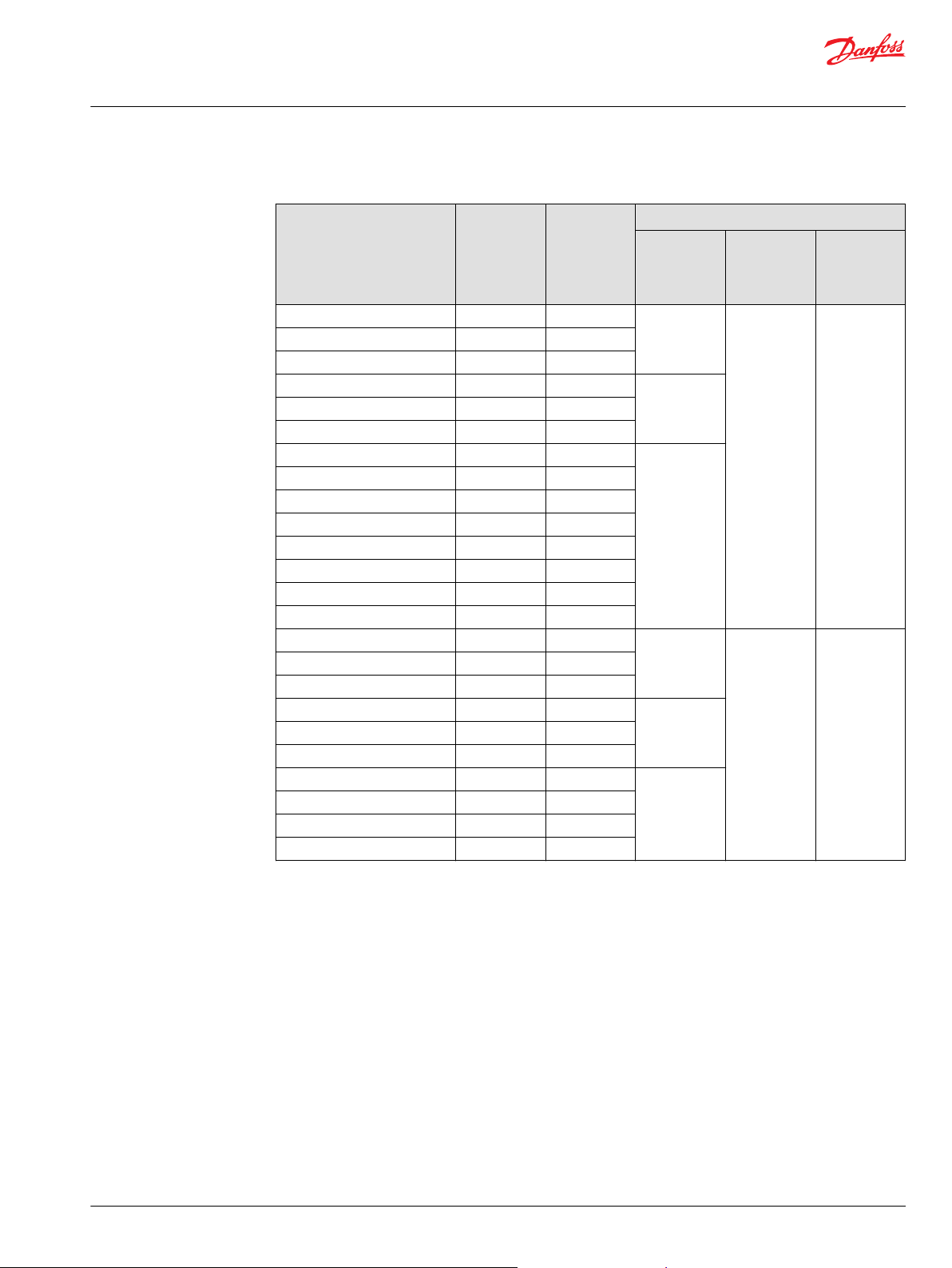
150-598.11
L
L
R
R
P
P
T
TLSLS
150-597.11
L
L
R
R
P
P
T
TLSLS
Technical Information
OSPB/C/F/D/L LS Steering Units, OLS Priority Valves, OSQ Flow Amplifiers
LS Steering Units OSPB, OSPC, OSPF, OSPD, OSPL
OSPC LSR: Steering unit load sensing dynamic with integrated valve functions
OSPC LSR (OLS)
Load sensing dynamic reaction
OSPF LS : Steering unit full drain load sensing dynamic and with integrated valve functions
OSPF LS (OLS)
Load sensing dynamic non-reaction
10 | © Danfoss | April 2021 BC152886483962en-001003
Page 11
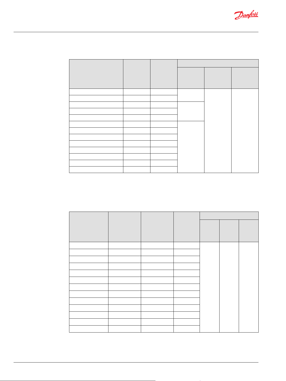
L R
150-599.11
LS
P T
L R
P
T
LS
Technical Information
OSPB/C/F/D/L LS Steering Units, OLS Priority Valves, OSQ Flow Amplifiers
LS Steering Units OSPB, OSPC, OSPF, OSPD, OSPL
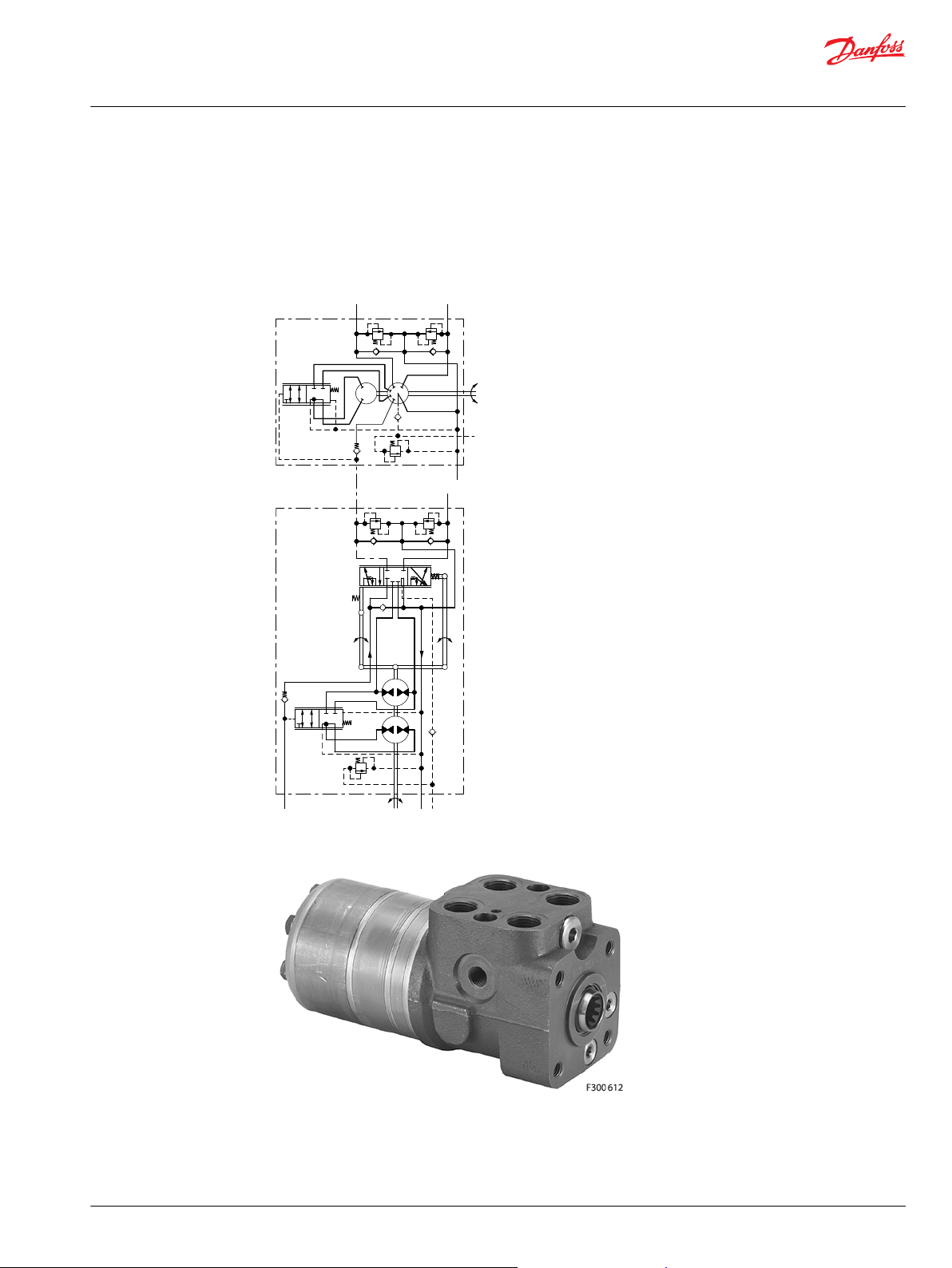
OSPD LS: Steering unit load sensing dynamic with 2 rotary meters and with integrated valve functions
The OSPD has 2 rotary meters (gear wheel sets). Should the pump supply be lost, only one rotary meter
will be active: OSPD displacement will be low for emergency steering (only one rotary meter active) for
pressure P-T <3 bar. Displacement will be high for pressure P-T >5 bars: both rotary meters are active.
OSPD LS (OLS)
Load sensing dynamic non-reaction
©
Danfoss | April 2021 BC152886483962en-001003 | 11
Page 12
150-301.11
L
L
R
R
P
P
T
TLSLS
150-601.10
L
L
R
R
P
P
T
T
LS
LS
Technical Information
OSPB/C/F/D/L LS Steering Units, OLS Priority Valves, OSQ Flow Amplifiers
LS Steering Units OSPB, OSPC, OSPF, OSPD, OSPL
OSPL LS:
Steering unit load sensing for high steering flow, displacement larger than 500 cm3/rev [30.5 in3/rev].
OSPL LS (OLS) - Load sensing static non-reaction
OSPL LS (OLS) - Load sensing dynamic non-reaction
12 | © Danfoss | April 2021 BC152886483962en-001003
Page 13
150-613.10
L
L
R
R
P
P
T
T
LS
LS
LS
Technical Information
OSPB/C/F/D/L LS Steering Units, OLS Priority Valves, OSQ Flow Amplifiers
LS Steering Units OSPB, OSPC, OSPF, OSPD, OSPL
OSPL 1200 (OLS) Load sensing dynamic non-reaction
©
Danfoss | April 2021 BC152886483962en-001003 | 13
Page 14
L
R
P
L
T
R
LS
150-310.12
P T LS
Technical Information
OSPB/C/F/D/L LS Steering Units, OLS Priority Valves, OSQ Flow Amplifiers
LS Steering Units OSPB, OSPC, OSPF, OSPD, OSPL
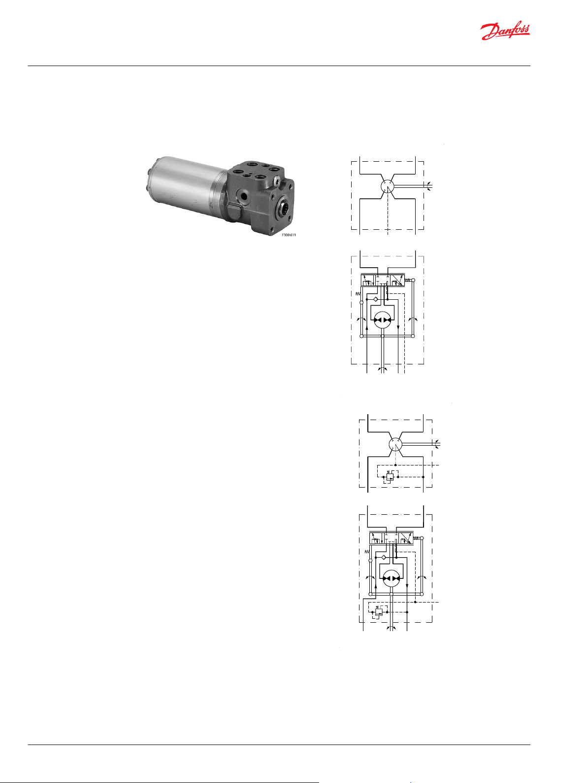
OSPBX LS, OSPCX LS and OSPLX LS: Steering units load sensing for flow amplifiers
OSPBX LS and OSPLX LS are load sensing steering units with the L and the R connections open to tank
when in neutral position. OSPBX LS and OSPLX LS can only be used with Danfoss flow-amplifiers OSQA or
OSQB. OSPBX LS and OSPLX LS steering units must not be connected directly to the steering cylinder.
OSPCX LS is for OSQ dynamic has per standard included check valve in P and check valve in LS
OSPBX LS, OSPLX LS - Load sensing static
14 | © Danfoss | April 2021 BC152886483962en-001003
Page 15
Technical Information
OSPB/C/F/D/L LS Steering Units, OLS Priority Valves, OSQ Flow Amplifiers
LS Steering Units OSPB, OSPC, OSPF, OSPD, OSPL
Code numbers and weights
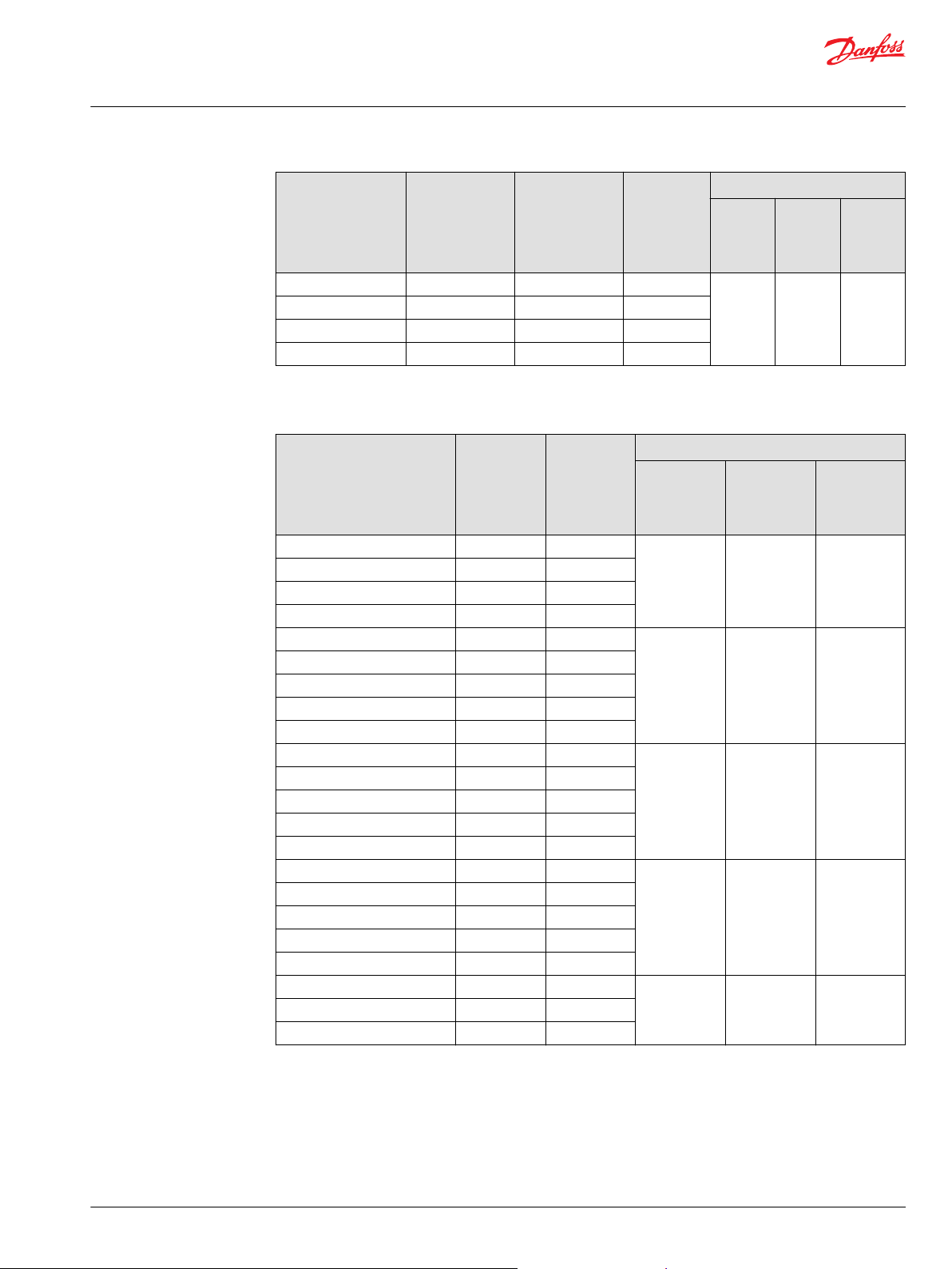
OSPB load sensing static non-reaction steering units
OSPB LS Static steering units have no valve functions.
OSPB LS in the table below have all standard neutral setting springs, see Specification Table for Non
Catalogue Numbers of LS Steering Units
Steering unit Code Numbers Weight
Connections
European version for OLS
G 1/2
**)
G 1/4 - S
OSPB 50 LS - 150G6085 5.2 [11.46]
OSPB 80 LS - 150G6086 5.3 [11.68]
OSPB 100 LS - 150G6087 5.4 [11.90]
OSPB 125 LS - 150G6088 5.5 [12.13]
OSPB 160 LS - 150G6089 5.6 [12.35]
OSPB 200 LS 150-0103 150G6090 5.8 [12.79]
OSPB 315 LS 150-0104 150-0116 6.2 [13.67]
OSPB 400 LS 150-0105 150-0117 7.0 [15.43]
*)
O-ring chamfer on port connections
**)
Spot face around port connection
US version for OLS
3/4-16 UNF - O
7/16-20 UNF - O*) + S
kg [lb]
*)
**)
Valve blocks OVP and OVR can be mounted on all of the OSPB steering units from the above table.
OSPB load sensing dynamic non-reaction steering units
OSPB LS Dynamic steering units have no valve functions.
OSPB LS in the table below have all standard neutral setting springs, see Specification Table for Non
Catalogue Numbers of LS Steering Units
Steering unit Code Numbers Weight
Connections
US version for OLS
3/4-16 UNF - O
7/16-20 UNF - O*) + S
OSPB 50 LS 150-8204 5.2 [11.46]
OSPB 80 LS 150-8205 5.3 [11.68]
OSPB 100 LS 150-8206 5.4 [11.90]
OSPB 125 LS 150-8207 5.5 [12.13]
OSPB 160 LS 150-8208 5.6 [12.35]
OSPB 200 LS 150-8209 5.8 [12.79]
OSPB 315 LS 150-8210 6.2 [13.67]
OSPB 400 LS 150-8211 7.0 [15.43]
*)
O-ring chamfer on port connections
**)
Spot face around port connection
*)
**)
kg [lb]
Valve blocks OVP and OVR can be mounted on all of the OSPB steering units from the above table
©
Danfoss | April 2021 BC152886483962en-001003 | 15
Page 16
Technical Information
OSPB/C/F/D/L LS Steering Units, OLS Priority Valves, OSQ Flow Amplifiers
LS Steering Units OSPB, OSPC, OSPF, OSPD, OSPL
OSPC load sensing static non-reaction steering unit
OSPC LS Static steering units in the table below incorporate all the following valve functions:
check valve in P-port
•
pilot pressure relief valve
•
shock valves
•
suction valves
•
OSPC LS in the table below have all standard neutral setting springs, see Specification Table for Non
Catalogue Numbers of LS Steering Units
Steering unit Code numbers Valve settings Weight
Connections Relief
European
for OLS
G 1/2
**)
G 1/4 - S
OSPC 80 LS 150-1230 150-1188 150-1222 170
OSPC 100 LS 150-1231 150-1189 150-1221 5.4 [11.90]
OSPC 125 LS 150-1232 150-1190 150-1220 5.5 [12.13]
OSPC 160 LS 150-1233 150-1191 150-1219 5.6 [12.35]
OSPC 200 LS 150-1234 150-1192 150-1218 5.8 [12.79]
OSPC 315 LS 150-1235 - 150G6091 6.2 [13.67]
OSPC 400 LS 150-1240 - - 7.0 [15.43]
*)
O-ring chamfer on port connections
**)
Spot face around port connections
European
and
US version
for OLSA
US version for OLS
3/4-16 UNF - O
7/16-20 UNF - O*) + S
Shock
valve
*)
bar [psi]
**)
[2465]
valve
bar [psi]
225
[3263]
kg [lb]
5.3 [11.68]
If you require other port connections, valve combinations and/or other valve settings or other
displacements, please fill in the order form in the Specification Table for Non Catalogue Numbers of LS
Steering Units and contact the Danfoss Sales Organization.
OSPC load sensing dynamic non-reaction steering units
OSPC LS Dynamic steering units in the table below incorporate all the following valve functions:
check valve in P-port
•
pilot pressure relief valve
•
shock valves
•
suction valves
•
check valve in LS-line for all OSPC LS Dynamic up to and including 200 cm³/rev
•
OSPC LS in the table below have all standard neutral setting springs, see Specification Table for Non
Catalogue Numbers of LS Steering Units
16 | © Danfoss | April 2021 BC152886483962en-001003
Page 17
Technical Information
OSPB/C/F/D/L LS Steering Units, OLS Priority Valves, OSQ Flow Amplifiers
LS Steering Units OSPB, OSPC, OSPF, OSPD, OSPL
Steering unit Code numbers Valve settings Weight
Connections Relief
European
version for OLS
**)
G 1/2 - S
**)
G 1/4 - S
OSPC 50 LS 150-8233 150-8222 150-8215 140
OSPC 80 LS 150-8234 150-8223 150-8216 170
OSPC 100 LS 150-8235 150-8224 150-8217 5.4 [11.90]
OSPC 125 LS 150-8236 150-8225 150-8218 5.5 [12.13]
OSPC 160 LS 150-8237 150-8226 150-8219 5.6 [12.35]
OSPC 200 LS 150-8238 150-8227 150-8220 5.8 [12.79]
OSPC 315 LS 150-8239 - 150-8221 6.2 [13.67]
OSPC 400 LS 150-8240 - - 7.0 [15.43]
**)
Spot face around port connections
*)
O-ring chamfer on port connections
European and
US version for
OLSA
US version
for OLS
3/4-16 UNF - O
7/16-20 UNF - O*)+S
Shock
valve
bar [psi]
*)
**)
[2030]
[2465]
valve
bar [psi]
200
[2900]
225
[3263]
kg [lb]
5.2 [11.46]
5.3 [11.68]
If you require other port connections, valve combinations and/or other valve settings or other
displacements please fill in the order form in the Specification Table for Non Catalogue Numbers of LS
Steering Units and contact the Danfoss Sales Organization.
OSPC load sensing dynamic reaction steering units
OSPC LSR Dynamic steering units in the table below incorporate all the following valve functions:
check valve in P-port
•
pilot pressure relief valve
•
shock valves
•
suction valves
•
check valve in LS-line
•
OSPC LSR in the table below have all standard neutral setting springs, see Specification Table for Non
Catalogue Numbers of LS Steering Units
Steering unit Code numbers Valve settings Weight
Connections
European version for OLS
**)
G 1/2 - S
**)
G 1/4 - S
OSPC 80 LSR 150-8241 170 [2465] 225 [3263] 5.3 [11.68]
OSPC 200 LSR 150-8242 5.8 [12.79]
**)
Spot face around port connections (can not be used in connection with OVR angular block)
Relief valve
bar [psi]
Shock valve
bar [psi]
kg [lb]
If you require other port connections, valve combinations, valve settings and/or other displacements,
please fill in the order form in the Specification Table for Non Catalogue Numbers of LS Steering Units and
contact the Danfoss Sales Organization.
OSPF load sensing dynamic non-reaction steering units
OSPF LS Dynamic steering units in the table below incorporate all the following valve functions:
©
Danfoss | April 2021 BC152886483962en-001003 | 17
Page 18
Technical Information
OSPB/C/F/D/L LS Steering Units, OLS Priority Valves, OSQ Flow Amplifiers
LS Steering Units OSPB, OSPC, OSPF, OSPD, OSPL
check valve in P-port
•
pilot pressure relief valve
•
shock valves
•
suction valves
•
OSPF LS in the table below have all soft neutral setting springs, see Specification Table for Non Catalogue
Numbers of LS Steering Units
Steering unit Code numbers Valve settings Weight
Connections
European version for OLS
**)
G 1/2 - S
**)
G 1/4 - S
OSPF 80 LS 150G5079 170 [2465] 225 [3263] 5.3 [11.68]
OSPF 100 LS 150G5080 5.4 [11.90]
OSPF 125 LS 150G5081 5.5 [12.13]
OSPF 160 LS 150G5082 5.6 [12.35]
OSPF 200 LS 150G5083 5.8 [12.79]
OSPF 315 LS 150G5084 6.2 [13.67]
OSPF 400 LS 150G5085 7.0 [15.43]
**)
Spot face around port connections (can not be used in connection with OVR angular block)
Relief valve
bar [psi]
Shock valve
bar [psi]
kg [lb]
If you require other port connections, valve combinations, valve settings and/or other displacements,
please fill in the order form in the Specification Table for Non Catalogue Numbers of LS Steering Units and
contact the Danfoss Sales Organization.
OSPD load sensing non-reaction steering units
OSPD LS Dynamic steering units in the table below incorporate all the following valve functions:
check valve in P-port
•
pilot pressure relief valve
•
shock valves
•
suction valves
•
check valve in LS-line
•
OSPD LS in the table below have all standard neutral setting springs, see Specification Table for Non
Catalogue Numbers of LS Steering Units
Steering unit Code numbers Valve settings Weight
Connections
European version
**)
G 1/2 - S
**)
G 1/4 - S
OSPD 70/230 LS 11113141 170 [2465] 225 [3263] 7.7 [17.00]
OSPD 70/270 LS 11113142 7.9 [17.41]
OSPD 70/385 LS 11113143 8.4 [18.52]
OSPD 125/325 LS 11113146 8.1 [12.79]
OSPD 125/440 LS 11113147 8.6 [18.96]
**)
Spot face around port connections (can not be used in connection with OVR angular block)
Relief valve
bar [psi]
Shock valve
bar [psi]
kg [lb]
If you require other port connections, valve combinations, valve settings and/or other displacements,
please fill in the order form in the Specification Table for Non Catalogue Numbers of LS Steering Units and
contact the Danfoss Sales Organization.
18 | © Danfoss | April 2021 BC152886483962en-001003
Page 19
Technical Information
OSPB/C/F/D/L LS Steering Units, OLS Priority Valves, OSQ Flow Amplifiers
LS Steering Units OSPB, OSPC, OSPF, OSPD, OSPL
OSPL load sensing static non-reaction steering units
OSPL LS Static steering units have no valve functions.
OSPL LS in the three tables below have all strong neutral setting springs, see Specification Table for Non
Catalogue Numbers of LS Steering Units
Steering unit Code numbers Weight
Connections
European version
for OLS
G 1/2
**)
G 1/4 - S
OSPL 520 LS 150-7169 150-7167 150-7168 8.1 [17.86]
OSPL 630 LS 150-7107 150-7164 150-7113 8.4 [18.52]
OSPL 800 LS 150-7108 150-7165 150-7114 8.8 [19.40]
OSPL 1000 LS 150-7110 150-7166 150-7115 10.0 [22.05]
**)
Spot face around port connection
*)
O-ring chamfer on port connections
US version for OLS
3/4-16 UNF - O*)*
7/16-20 UNF - O* +
**)
S
US version for OLS
and OVPL LS - port
7/16-20 UNF - O* +
**)
S
kg [lb]
OSPL load sensing dynamic non-reaction steering units
OSPL LS Dynamic steering units in the table below have no valve functions.
Steering unit Code numbers Weight
Connections
US version for OLS
3/4-16 UNF - O
7/16-20 UNF - O*)* +S
OSPL 520 LS 150-8243 8.1 [17.86]
OSPL 630 LS 150-8212 8.4 [18.52]
OSPL 800 LS 150-8213 8.8 [19.40]
OSPL 1000 LS 150-8214 10.0 [22.05]
*)
O-ring chamfer on port connections
**)
Spot face around port connection
*)
**)
kg [lb]
OSPL LS Dynamic steering units in the table below incorporate all the following valve function:
•
pilot pressure relief valve
Steering unit Code numbers Valve settings Weight
Connections
European version
for OLS and OVPL
LS: G 1/4 - S
OSPL 520 LS 150-8244 170 [2465] 8.1 [17.86]
OSPL 1000 LS 150-8245 10.0 [22.05]
**)
Spot face around port connection
**)
Relief valve
bar [psi]
kg [lb]
If you require other displacements or other valve setting, please fill in the order form in the Specification
Table for Non Catalogue Numbers of LS Steering Units and contact the Danfoss Sales Organization.
OSPL 1200 LS Dynamic steering unit in the table below incorporate all the following valve function:
©
Danfoss | April 2021 BC152886483962en-001003 | 19
Page 20
Technical Information
OSPB/C/F/D/L LS Steering Units, OLS Priority Valves, OSQ Flow Amplifiers
LS Steering Units OSPB, OSPC, OSPF, OSPD, OSPL
•
shock valves
•
suction valves
OSPL 1200 LS in the table below has strong neutral setting springs, see Specification Table for Non
Catalogue Numbers of LS Steering Units
Steering unit
OSPL 1200 LS 150-7175 280 [4061] 11 [24.25]
*)
O-ring chamfer on port connections
**)
Spot face around port connection
Code numbers Valve settings Weight
Connections
US version for OLS
3/4 - 16 UNF - O
CF: 11/16 - 12 UN
7/16 - 20 UNF - O*)* + S
*)
Shock valves
bar [psi]
**)
kg [lb]
If you require other displacements or other valve setting, please fill in the order form in the Specification
Table for Non Catalogue Numbers of LS Steering Units and contact the Danfoss Sales Organization.
OSPBX and OSPLX load sensing static steering units for OSQ static
OSPBX LS and OSPLX LS Static steering units in the table below have no valve functions.
OSPBX LS in the table below have all standard neutral setting springs, see Specification Table for Non
Catalogue Numbers of LS Steering Units
OSPLX LS in the table below have all strong neutral setting springs, see Specification Table for Non
Catalogue Numbers of LS Steering Units
Steering unit Code numbers Weight
Connections
European version
G 1/2
**)
G 1/4 - S
OSPBX 160 LS 150-1082 150-1078 5.6 [12.35]
OSPBX 200 LS 150-1083 150-1079 5.8 [12.79]
OSPBX 315 LS 150-1084 150-1080 6.2 [13.67]
OSPBX 400 LS 150-1085 150-1081 7.0 [15.43]
OSPLX 520 LS 150-7170 150-7173 8.1 [17.86]
OSPLX 630 LS 150-7171 150-7174 8.4 [18.52]
OSPLX 800 LS 150-7172 150-7155 8.8 [19.40]
**)
Spot face around port connection
*)
O-ring chamfer on port connections
US version
3/4-16 UNF - O
7/16-20 UNF - O*)* + S
*)
kg [lb]
**)
OSPCX load sensing dynamic steering units for OSQ dynamic
OSPCX LS Dynamic steering unit in the table below incorporates the following valve function:
pilot pressure relief valve
•
See Specification Table for Non Catalogue Numbers of LS Steering Units
If you require other displacements or other valve setting, please fill in the order form in the Specification
Table for Non Catalogue Numbers of LS Steering Units and contact the Danfoss Sales Organization.
20 | © Danfoss | April 2021 BC152886483962en-001003
Page 21
Technical Information
OSPB/C/F/D/L LS Steering Units, OLS Priority Valves, OSQ Flow Amplifiers
LS Steering Units OSPB, OSPC, OSPF, OSPD, OSPL
Specification table for non catalogue numbers of LS Steering Units
Fill in your company data and place x’s in the table where appropriate, then send to your Danfoss Sales
Organization.
Your
company
Steering unit
type
Reaction type LS ( Non-reaction) LSR (Reaction: only OSPC, OSPD)
Load Sensing
type
DP, cm³/rev
OSPC LS
OSPF LS
DP, cm³/rev
OSPC LSR
DP, cm³/rev
OSPD LS
DP, cm³/rev
OSPD LSR
DP, cm³/rev
OSPL, OSPLX
DP, cm³/rev
OSPBX LS
OSPCX LS
Port threads
OSPC, OSPF
Name Vehicle Potential pcs/year Completed by Date
OSPC OSPF OSPD OSPL OSPBX OSPCX OSPLX
Static (Only OSPC, OSPL, OSPBX, OSPCX, OSPLX) Dynamic
40 50 60 70 80 100 125 160 185 200 230 250 315 400
40 50 60 70 80 100 125 160 185 200
60/185 60/220 60/260 70/195 70/230 70/270 70/385 100/200 100/260 100/300 125/285 125/325 125/440
60/185 60/220 70/195 70/230 100/200
520 630 800 1000 1200 (only OSPL)
160 200 250 315 400
G1/2 G1/2- S** M18 × 1.5 - O* + S** 3/4-16 UNF - O* for OLSA (only OSPC)
Port threads
OSPD
Port threads
OSPL, OSPLX
Relief
valve***
bar
Shock valves
bar
Suction
valves
Check valve
in LS
Neutral
setting
springs
Unit black
painted
©
Danfoss | April 2021 BC152886483962en-001003 | 21
G1/2- S** M18 × 1.5 - O* + S** 3/4-16 UNF - O*
G1/2 3/4-16 UNF - O* For OPVL and without RV (LS = 7/16 - 20
UNF)
70 80 90 100 110 120 140 170 190 200 210 no relief valve
160 180 200 225 240 280 no shock valves
Yes No
Yes (Only for OSPC dynamic and OSPD) No (Only for OSPC, OSPF and OSPL)
Soft:
0.5 - 1.8 Nm in normal steering situations
Yes No
Standard:
0.8 - 3 Nm in normal steering situations
For OVPL and with RV (LS = G 1/4)
Strong:
1.5 - 4 Nm in normal steering situations
Page 22
Technical Information
OSPB/C/F/D/L LS Steering Units, OLS Priority Valves, OSQ Flow Amplifiers
LS Steering Units OSPB, OSPC, OSPF, OSPD, OSPL
DP = Displacement, RV = Pilot pressure relief valve.
O*: O-ring chamfer on port connections.
S**: Spot face around port connections (can not be used in connection with OVR angular block).
RV*** see Technical data for limitation in maximum pressure depending on displacements.
Types not mentioned with port connections in the table above, are only available in the version(s) stated
in the code number tables.
An alternative way to specify a variant is to state an existing code number and add the modifications, you
would like to have implemented in the basic steering unit.
Code number of basic steering unit: __________________________________________________
Requested modifications: ___________________________________________________________
Technical data
Common data, refer to General Steering Components Technical Information, BC152886484183.
Displacement, flow and pressure: OSPB LS, OSPC LS, OSPC LSR
OSPB LS, OSPC LS, OSPC LSR
Steering unit Displacement
cm³/rev
[in³/rev]
OSPC 40 LS Static 40 [2.44] 4 [1.06] 140 [2030] 40 [580] 280 [4061]
OSPB/OSPC 50 LS Static 50 [3.05] 5 [1.32]
OSPC 60 LS Static 60 [3.66] 6 [1.58]
OSPC 70 LS Static 70 [4.27] 7 [1.85] 175 [2538]
OSPB/OSPC 80 LS Static 80 [4.88] 8 [2.11]
OSPB/OSPC 100 LS Static 100 [6.10] 10 [2.64]
OSPB/OSPC 125 LS Static 125 [7.63] 13 [3.43] 210 [3045]
OSPB/OSPC 160 LS Static 160 [9.76] 16 [4.23]
OSPC 185 LS Static 185 [11.29] 19 [5.02]
OSPB/OSPC 200 LS Static 200 [12.20] 20 [5.28]
OSPC 230 LS Static 230 [14.03] 23 [6.07]
OSPC 250 LS Static 250 [15.25] 25 [6.60]
OSPB/OSPC 315 LS Static 315 [19.22] 32 [8.45]
OSPB/OSPC 400 LS Static 400 [24.41] 40 [10.57]
*
Rated flow at 100 rpm.
**
Any OSPB/C LS Static can withstand 210 bar in maximum system pressure. However, OSPB/C with small gear wheel
set and high pressure will have relatively high slippage values.
Rated oil
*
flow
l/min
[US gal/min]
Max. pressure, bar (psi)
System
pressure
P-T port
pressure
T,
**
absolute
port
pressure
L-T/R-T
port
pressure
22 | © Danfoss | April 2021 BC152886483962en-001003
Page 23
Technical Information
OSPB/C/F/D/L LS Steering Units, OLS Priority Valves, OSQ Flow Amplifiers
LS Steering Units OSPB, OSPC, OSPF, OSPD, OSPL
OSPB LS, OSPC LS, OSPC LSR
Steering unit Displacement
cm³/rev
[in³/rev]
OSPC 40 LS Dynamic 40 [2.44] 4 [1.06] 140 [2030] 40 [580] 280 [4061]
OSPB/OSPC 50 LS Dynamic 50 [3.05] 5 [1.32]
OSPC 60 LS Dynamic 60 [3.66] 6 [1.58]
OSPC 70 LS Dynamic 70 [4.27] 7 [1.85] 175 [2538]
OSPB/OSPC 80 LS Dynamic 80 [4.88] 8 [2.11]
OSPB/OSPC 100 LS Dynamic 100 [6.10] 10 [2.64]
OSPB/OSPC 125 LS Dynamic 125 [7.63] 13 [3.43] 210 [3045]
OSPB/OSPC 160 LS Dynamic 160 [9.76] 16 [4.23]
OSPC 185 LS Dynamic 185 [11.29] 19 [5.02]
OSPB/OSPC 200 LS Dynamic 200 [12.20] 20 [5.28]
OSPC 230 LS Dynamic 230 [14.03] 23 [6.07]
OSPC 250 LS Dynamic 250 [15.25] 25 [6.60]
OSPB/OSPC 315 LS Dynamic 315 [19.22] 32 [8.45]
OSPB/OSPC 400 LS Dynamic 400 [24.41] 40 [10.57]
OSPC 40 LSR Dynamic 40 [2.44] 4 [1.06] 140 [2030] 40 [580] 280 [4061]
OSPC 50 LSR Dynamic 50 [3.05] 5 [1.32]
OSPC 60 LSR Dynamic 60 [3.66] 6 [1.58]
OSPC 70 LSR Dynamic 70 [4.27] 7 [1.85] 175 [2538]
OSPC 80 LSR Dynamic 80 [4.88] 8 [2.11]
SPC 100 LSR Dynamic 100 [6.10] 10 [2.64]
OSPC 125 LSR Dynamic 125 [7.63] 13 [3.43] 210 [3045]
OSPC 160 LSR Dynamic 160 [9.76] 16 [4.23]
OSPC 185 LSR Dynamic 185 [11.29] 19 [5.02]
OSPC 200 LSR Dynamic 200 [12.20] 20 [5.28]
*
Rated flow at 100 rpm.
**
Any OSPB/C LS Dynamic can withstand 210 bar in maximum system pressure. However, OSPB/C with small gear
wheel set and high pressure will have relatively high slippage values.
Rated oil
*
flow
l/min
[US gal/min]
Max. pressure, bar (psi)
System
pressure
P-T port
pressure
T,
**
absolute
port
pressure
L-T/R-T
port
pressure
©
Danfoss | April 2021 BC152886483962en-001003 | 23
Page 24
Technical Information
OSPB/C/F/D/L LS Steering Units, OLS Priority Valves, OSQ Flow Amplifiers
LS Steering Units OSPB, OSPC, OSPF, OSPD, OSPL
Displacement, flow and pressure: OSPF LS
Steering unit Displacement
OSPF 50 LS Dynamic 50 [3.05] 5 [1.32] 140 [2030] 40 [580] 280 [4061]
OSPF 60 LS Dynamic 60 [3.66] 6 [1.58]
OSPF 70 LS Dynamic 70 [4.27] 7 [1.85] 175 [2538]
OSPF 80 LS Dynamic 80 [4.88] 8 [2.11]
OSPF 100 LS Dynamic 100 [6.10] 10 [2.64]
OSPF 125 LS Dynamic 125 [7.63] 13 [3.43] 210 [3045]
OSPF 160 LS Dynamic 160 [9.76] 16 [4.23]
OSPF 185 LS Dynamic 185 [11.29] 19 [5.02]
OSPF 200 LS Dynamic 200 [12.20] 20 [5.28]
OSPF 230 LS Dynamic 230 [14.03] 23 [6.07]
OSPF 250 LS Dynamic 250 [15.25] 25 [6.60]
OSPF 315 LS Dynamic 315 [19.22] 32 [8.45]
OSPF 400 LS Dynamic 400 [24.41] 40 [10.57]
*
Rated flow at 100 rpm.
**
Any OSPB/C/F LS Dynamic can withstand 210 bar in max. system pressure. However OSPB/C/F w. small gear wheel
cm³/rev [in³/
rev]
Rated oil
*
flow
l/min [US gal/
min]
Max. pressure, bar (psi)
System
pressure
P-T port
pressure
**
T, absolute
port pressure
L-T/R-T port
pressure
set and high pressure will have relatively high slippage values.
Displacement, flow and pressure: OSPD LS
OSPD steering units in the table below are all Load Sensing Dynamic type.
Steering unit Displacement
manual steer
mode
cm³/rev
[in³/rev]
OSPD 60/185 LS 60 [3.66] 185 [11.29] 19 [5.02] 210 [3045] 40 [580] 280 [4061]
OSPD 60/220 LS 60 [3.66] 220 [13.42] 22 [5.81]
OSPD 60/260 LS 60 [3.66] 260 [15.87] 26 [6.87]
OSPD 70/195 LS 70 [4.27] 195 [11.90] 20 [5.28]
OSPD 70/230 LS 70 [4.27] 230 [14.03] 23 [6.07]
OSPD 70/270 LS 70 [4.27] 270 [16.48] 27 [7.13]
OSPD 70/385 LS 70 [4.27] 385 [23.49] 39 [10.30]
OSPD 100/200 LS 100 [6.10] 200 [12.20] 20 [5.28]
OSPD 100/260 LS 100 [6.10] 260 [15.87] 26 [6.87]
OSPD 100/300 LS 100 [6.10] 300 [18.31] 30 [7.93]
OSPD 125/285 LS 125 [7.63] 285 [17.39] 29 [7.66]
OSPD 125/325 LS 125 [7.63] 325 [19.83] 33 [8.72]
OSPD 125/440 LS 125 [7.63] 440 [26.85] 44 [11.62]
Displacement
normal steer
mode
cm³/rev
[in³/rev]
Rated oil
*
flow
l/min
[US gal/min]
Max. pressure, bar (psi)
System
Pressure
P-T port
pressure
T,
absolute
port
pressure
L-T/R-T
port
pressure
24 | © Danfoss | April 2021 BC152886483962en-001003
Page 25
Technical Information
OSPB/C/F/D/L LS Steering Units, OLS Priority Valves, OSQ Flow Amplifiers
LS Steering Units OSPB, OSPC, OSPF, OSPD, OSPL
Steering unit Displacement
manual steer
mode
cm³/rev
[in³/rev]
Displacement
normal steer
mode
cm³/rev
[in³/rev]
Rated oil
*
flow
l/min
[US gal/min]
Max. pressure, bar (psi)
System
Pressure
P-T port
pressure
T,
absolute
port
pressure
L-T/R-T
port
pressure
OSPD 60/185 LSR 60 [3.66] 185 [11.29] 19 [5.02] 210 [3045] 40 [580] 280 [4061]
OSPD 60/220 LSR 60 [3.66] 220 [13.42] 22 [5.81]
OSPD 70/195 LSR 70 [4.27] 195 [11.90] 20 [5.28]
OSPD 100/200 LSR 100 [6.10] 200 [12.20] 20 [5.28]
*
Rated flow at 100 rpm.
Displacement, flow and pressure: OSPL LS, OSPBX LS, OSPCX LS, OSPLX LS
Steering unit Displacement
cm³/rev
[in³/rev]
OSPL 520 LS Static 520 [31.73] 52 [13.74] 240 [3480] 40 [580] 280 [4061]
OSPL 630 LS Static 630 [38.44] 63 [16.64]
OSPL 800 LS Static 800 [48.82] 80 [21.10]
OSPL 1000 LS Static 1000 [61.02] 100 [26.40]
OSPL 520 LS Dynamic 520 [31.73] 52 [13.74] 240 [3080] 40 [580] 280 [4061]
OSPL 630 LS Dynamic 630 [38.44] 63 [16.64]
OSPL 800 LS Dynamic 800 [48.82] 80 [21.10]
OSPL 1000 LS Dynamic 1000 [61.02] 100 [26.40]
OSPL 1200** Dynamic 1200 [73.22] 100 [26.40]
OSPBX 160 LS Static 160 [9.76] 16 [4.23] 210 [3045] 40 [580] 280 [4061]
OSPBX 200 LS Static 200 [12.20] 20 [5.28]
OSPBX 250 LS Static 250 [15.25] 25 [6.60]
OSPBX 315 LS Static 315 [19.22] 32 [8.45]
OSPBX 400 LS Static 400 [24.41] 40 [10.57]
OSPCX 160 LS Dynamic 160 [9.76] 16 [4.23] 210 [3045] 40 [580] 280 [4061]
OSPCX 200 LS Dynamic 200 [12.20] 20 [5.28]
OSPCX 250 LS Dynamic 250 [15.25] 25 [6.60]
OSPCX 315 LS Dynamic 315 [19.22] 32 [8.45]
OSPCX 400 LS Dynamic 400 [24.41] 40 [10.57]
OSPLX 520 LS Static 520 [31.73] 52 [13.74] 240 [3480] 40 [580] 280 [4061]
OSPLX 630 LS Static 630 [38.44] 63 [16.64]
OSPLX 800 LS Static 800 [48.82] 80 [21.10]
*
Rated flow at 100 rpm.
**
OSPL 1200 max speed at 100l/min [26.4 US gal/min] 83 rpm.
Rated oil
*
flow
l/min
[US gal/min]
Max. pressure, bar (psi)
System
pressure
P-T port
pressure
T,
absolute
port
pressure
L-R
port
pressure
©
Danfoss | April 2021 BC152886483962en-001003 | 25
Page 26
3000
2500
2000
1500
1000
0
200
180
160
140
120
100
80
60
0
psi bar
152B79.10
0 10 20 30 40 50 60 70 80 l/min
P-T P-T
Q
p
Q
p
0 2 4 6 8 10 12 14 16 18 20 US gal/min
A
B
OSPC/OSPF/OSPD/OSPU/OSPL LS+OLS 80
Technical Information
OSPB/C/F/D/L LS Steering Units, OLS Priority Valves, OSQ Flow Amplifiers
LS Steering Units OSPB, OSPC, OSPF, OSPD, OSPL
Valve functions in OSPC, OSPF, OSPD and OSPL LS steering units
Pilot pressure relief valve; (P - T, Qp) characteristic
The pilot pressure relief valve protects the steering unit against excessive pressure. The pilot pressure
relief valve in the OSPC LS, OSPF LS, OSPD LS and OSPL LS steering unit together with the priority valve
limit the maximum steering pressure P-T. The pilot pressure relief valve is set at an oil flow to the priority
valve of 25 l/min [6.60 US gal/min].
For OSPC, OSPD and OSPL load sensing dynamic steering units, the setting values are valid at a dynamic
flow of 0.6 l/min [0.16 US gal/min].
For OSPF load sensing dynamic steering units, the setting values are valid at a dynamic flow of 1.1 l/min
[0.29 US gal/min].
Setting tolerance:
</= 170 bar [2465 psi]: rated value +5 bar [72.5 psi].
> 170 bar [2465 psi]: rated value +10 bar [145 psi].
A = 170 + 5 bar [2465+ 73 psi]
B = 140 + 5 bar [2030 + 73 psi]
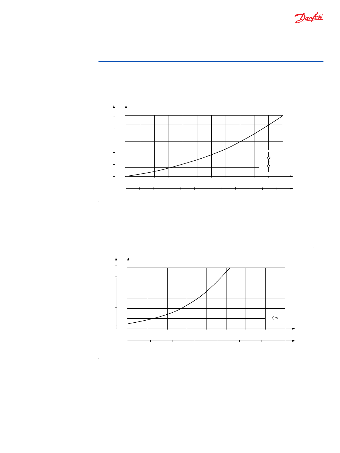
Shock valves
The shock valves protect the steering unit and reduce external forces on the steering cylinder by limiting
the pressure difference from L to T and from R to T.
The shock valves are set at 3 l/min [0.792 US gal/min]
At higher flow pressure peaks may occur.
26 | © Danfoss | April 2021 BC152886483962en-001003
The shock valves are of the direct acting type, so they react very quickly.
Setting tolerance: rated value +20 bar [290 psi].
Suction valves
The suction valves allow oil suction to avoid cavitation in the steering cylinder. To provide correct
suction, a back pressure valve must be fitted in the tank line from the steering unit.
Generally Danfoss recommend a back pressure of 2 bar [29 psi], but on vehicles with strong self
straightening tendencies and on articulated steered vehicles, we recommend 5-10 bar [72.5 - 145 psi]. For
further advice, please contact the Danfoss Sales Organization.
Page 27
100
80
60
40
20
0
7
6
5
4
3
2
1
0
psi bar
150-374.10
0 1 2 3 4 5 6 7 8 9 10 11 l/min
T-R
T-L
T-R
T-L
Q
p
Q
p
0 0.25 0.50 0.75 1 1.25 1.50 1.75 2 2.25 2.50 2.75 US gal/min
90
75
60
45
30
15
0
6
5
4
3
2
1
0
psi bar
150-375.11
0 10 20 30 40 50 60 70 80 l/min
Q
p
Q
p
0 3 6 9 12 15 18 21 US gal/min
∆ p ∆ p
Technical Information
OSPB/C/F/D/L LS Steering Units, OLS Priority Valves, OSQ Flow Amplifiers
LS Steering Units OSPB, OSPC, OSPF, OSPD, OSPL
A connection which incorporates a check valve must be established to allow oil flow to by-pass the back
pressure valve (and filter) from the tank to steering unit. See diagram examples in sub catalogue “General
Steering Components” page 37 - 39.
Check valves
The check valve in the P connection of the steering unit protects the driver against steering wheel jerks.
The check valve prevents oil from flowing backwards into the pump line when steering against a high
pressure on the cylinder side. The pressure drop across the check valve is indicated on the following
graph, which assumes the use of port adapters with 11 mm [0.43 in] minimum bore.
©
Danfoss | April 2021 BC152886483962en-001003 | 27
The check valve in the LS line of OSPC LS and OSPD LS dynamic steering units also protects the driver
against steering wheel jerks. The check valve prevents oil from flowing backwards into the LS line to the
priority valve when steering against a high pressure on the cylinder side.
In OSPF LS oil cannot flow backwards into the LS line, look in sub catalogue: “General Steering
Components “ page 26.
Page 28

K
min.Ø21[0.83]
min.12[0.479]
A
30°
1[0.04]
150-603.10-A
min.12[0.47]
min.Ø28[1.10]
B
30°
L
150-603.10-B
150-603.10-C
min.15[0.59]
Ø21.5[0.846]
M
C
150-603.10-D
0.6[0.024]
Ø28.3[1.114]
Ø28.6[1.126]
N
min.15[0.59]
D
Technical Information
OSPB/C/F/D/L LS Steering Units, OLS Priority Valves, OSQ Flow Amplifiers
LS Steering Units OSPB, OSPC, OSPF, OSPD, OSPL
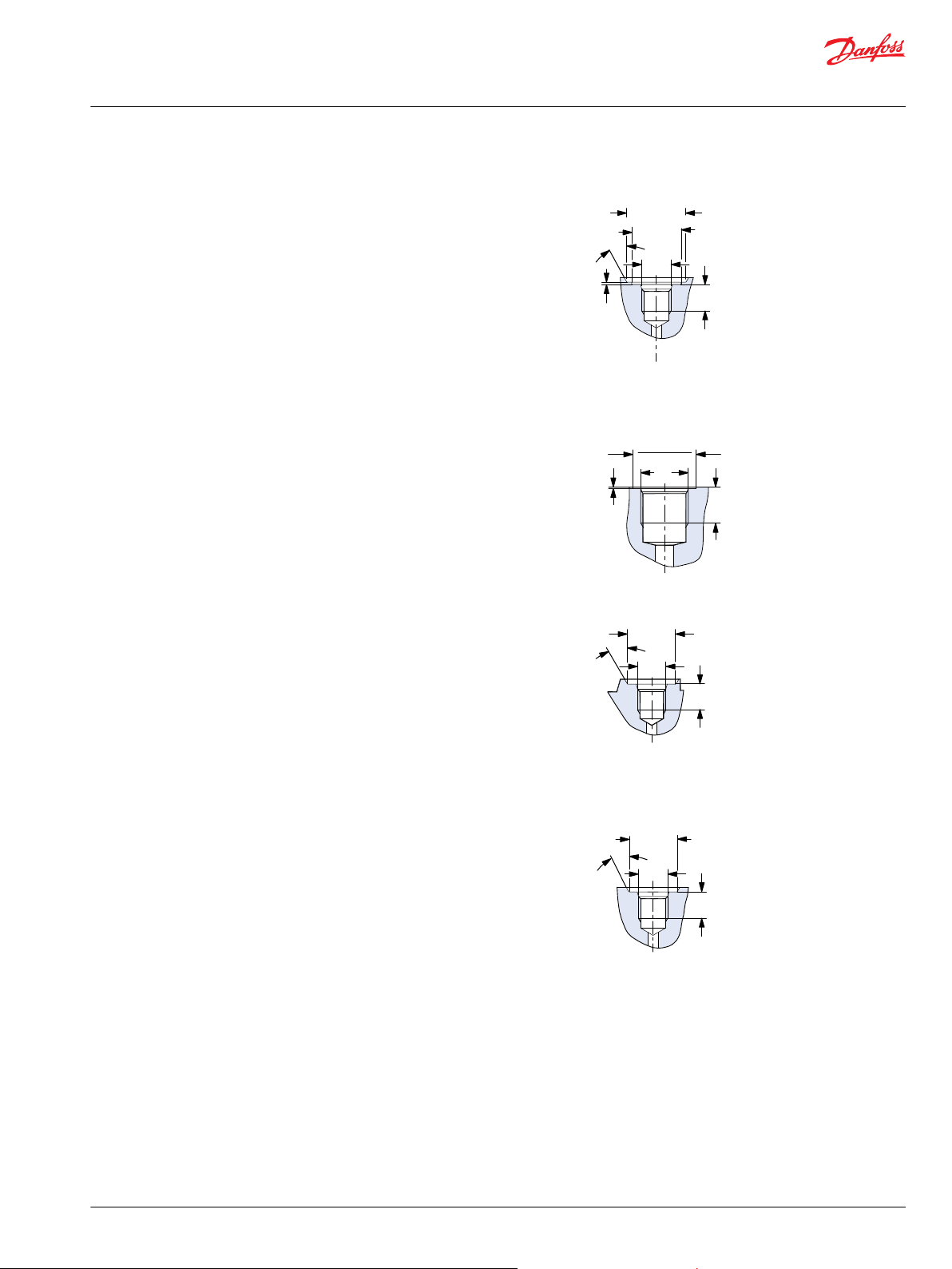
Port thread versions for OSPB LS, OSPC LS/LSR, OSPF LS, OSPD LS/LSR, OSPL LS, OSPBX LS, OSPCX LS, OSPLX LS
A: G port w. spot face (LS in OSPB and OSPL with no
valves)
K: DIN 3852-2 - G 1/4
B: G port w. spot face (LS in OSPC/F/D/Q and OSPL with
valves)
L: DIN 3852-2 - G 1/4
C: G ports (P, T, L, R)
M: DIN 3852-2 - G 1/2
D: G ports w. spot face (P, T, L, R)
N: DIN 3852-2 - G 1/2
28 | © Danfoss | April 2021 BC152886483962en-001003
Page 29
150-603.10-E
O
1[0.04]
min.11.5[0.453]
min.Ø22[0.87]
min.Ø26[1.02]
30°
E
150-603.10-F
0.6[0.024]
Ø28.6[1.126]
Ø28.3[1.114]
P
min.15[0.59]
F
150-603.10-G
G
30°
min.Ø21[0.83]
Q
min.11.5[0.45]
150-603.10-H
min.11.5[0.45]
min.Ø21[0.83]
30°
R
H
Technical Information
OSPB/C/F/D/L LS Steering Units, OLS Priority Valves, OSQ Flow Amplifiers
LS Steering Units OSPB, OSPC, OSPF, OSPD, OSPL
E: Metric port w. spot face and O-ring chamfer (LS)
O: ISO 6149-1 - M12 x 1.5
F: Metric ports w. spot face and O-ring chamfer (P, T, L, R)
P: ISO 6149-1 - M18 x 1.5
G: UNF port w. O-ring chamfer (LS in OSPB and OSPL with
no valves)
Q: ISO 11926-1 - 7/16-20UNF O-ring boss port
H: UNF ports w. O-ring chamfer (LS in OSPC/ F/D and
OSPL with valves)
R: ISO 11926-1 - 7/16-20 UNF O-ring boss port
©
Danfoss | April 2021 BC152886483962en-001003 | 29
Page 30

150-603.10-I
min.15[0.59]
Ø20.8[0.819]
S
I
Technical Information
OSPB/C/F/D/L LS Steering Units, OLS Priority Valves, OSQ Flow Amplifiers
LS Steering Units OSPB, OSPC, OSPF, OSPD, OSPL
I: UNF ports w. O-ring chamfer (P, T, L, R)
S: ISO 11926-1 - 3/4-16UNF O-ring boss port
30 | © Danfoss | April 2021 BC152886483962en-001003
Page 31

150-590.11
66 [2.60]
Ø44.4 [1.748]
Ø25.4 [1.000]
44 [1.73]
44 [1.73]
47 [1.85]
max. 87 [3.42]
Ø91 [3.58]
64 [2.52]
2.8 [0.110]
min. 7.1 [0.280]
7 [0.28]
45˚
Ø82.3 [3.240]
Ø81.7 [3.217]
57 [2.24]
85 [3.35]
102 [4.02]
44 [1.73]
29 [1.14]
LS
B
A
L
2
L
1
LS
R
L
T P
Technical Information
OSPB/C/F/D/L LS Steering Units, OLS Priority Valves, OSQ Flow Amplifiers
LS Steering Units OSPB, OSPC, OSPF, OSPD, OSPL
Dimensions
OSPB LS for OLS, OSPBX LS for OSQ
Dimensions for OSPB LS for OLS, OSPBX LS for OSQ
Type L1mm
[in]
OSPB 50 126 [4.96] 6.5 [0.26]
OSPB 80 129 [5.08] 10.4 [0.41]
OSPB 100 132 [5.20] 13.0 [0.51]
OSPB 125 135 [5.31] 16.2 [0.64]
OSPB/OSPBX 160 140 [5.51] 20.8 [0.82]
OSPB/OSPBX 200 145 [5.71] 26.0 [1.02]
OSPB/OSPBX 250 151 [5.94] 32.5 [1.28]
OSPB/OSPBX 315 160 [6.30] 40.9 [1.61]
OSPB/OSPBX 400 171 [6.73] 52.0 [2.05]
L2mm
[in]
Dimensions for OSPB LS for OLS, OSPBX LS for OSQ
©
Danfoss | April 2021 BC152886483962en-001003 | 31
Page 32

Technical Information
OSPB/C/F/D/L LS Steering Units, OLS Priority Valves, OSQ Flow Amplifiers
LS Steering Units OSPB, OSPC, OSPF, OSPD, OSPL
European version: US version:
A: G 1/2; 15 mm [0.59 in] deep A: 3/4 - 16 UNF O-ring boss; 15 mm [0.59 in] deep
B: M10 × 1.5, 16 mm [0.63 in] deep B: 3/8 - 16 UNC, 16 mm [0.63 in] deep
LS: G ¼ with spot face, 11 mm [0.43 in] deep LS: G 7/16 - 20 UNF O-ring boss, 11.5 mm [0.45 in] deep
32 | © Danfoss | April 2021 BC152886483962en-001003
Page 33
Technical Information
OSPB/C/F/D/L LS Steering Units, OLS Priority Valves, OSQ Flow Amplifiers
LS Steering Units OSPB, OSPC, OSPF, OSPD, OSPL
OSPC LS/LSR and OSPF LS for OLS, OSPCX LS for OSQ
Type L
OSPC 40 126 [4.96] 6.5 [0.26]
OSPC/OSPF 50 126 [4.96] 6.5[0.26]
OSPC/OSPF 60 128 [5.04] 9.1 [0.36]
OSPC/OSPF 70 128 [5.04] 9.1 [0.36]
OSPC/OSPF 80 129 [5.08] 10.4 [0.41]
OSPC/OSPF 100 132 [5.20] 13.0 [0.51]
OSPC/OSPF 125 135 [5.31] 16.2 [0.64]
OSPC/OSPF OSPCX 160 140 [5.51] 20.8 [0.82]
OSPC/OSPF 185 143 [5.63] 24.0 [0.94]
OSPC/OSPF OSPCX 200 145 [5.71] 26.0 [1.02]
OSPC/OSPF 230 149 [5.87] 29.9 [1.18]
OSPC/OSPF OSPCX 250 151 [5.94] 32.5 [1.28]
OSPC/OSPF OSPCX 315 160 [6.30] 40.9 [1.61]
OSPC/OSPF/OSPCX 400 171 [6.73] 52.0 [2.05]
1
mm [in]
L
2
mm [in]
©
Danfoss | April 2021 BC152886483962en-001003 | 33
Page 34

150-591.11
35 [1.38]
Ø44.4 [1.748]
Ø25.4 [1.000]
44 [1.73]
51 [2.01]
2.8 [0.110]
min. 7.1 [0.280]
7 [0.28]
44 [1.73]
29 [1.14]
LS
LS
A
L
2
L
1
R
L
T P
R
L
T P
38 [1.50]
47 [1.85]
max. 87 [3.42]
Ø91 [3.58]
45˚
Ø82.3 [3.240]
Ø81.7 [3.217]
57 [2.24]
85 [3.35]
102 [4.02]
B
LS
Technical Information
OSPB/C/F/D/L LS Steering Units, OLS Priority Valves, OSQ Flow Amplifiers
LS Steering Units OSPB, OSPC, OSPF, OSPD, OSPL
European version: US version:
A: G 1/2 or G 1/2 w. spot face
or M18 x 1.5 ISO 6149,
A: 3/4-16 UNF O-ring boss,
15 mm (0.59 in) deep
15 mm [0.59 in] deep
B: M10 x 1.5, 16 mm [0.63 in] deep B: 3/8 - 16 UNC or M10 x 1.5, 16 mm [0.63 in] deep
LS: G 1/4 w. spot face
or M12 x 1.5 ISO 6149,
LS: 7/16 - 20 UNF O-ring boss,
11.5 mm [0.45 in] deep
11.5 mm [0.45 in] deep
34 | © Danfoss | April 2021 BC152886483962en-001003
Page 35

150-593.12
35 [1.38]
Ø44.4 [1.748]
Ø25.4 [1.000]
38 [1.50]
44 [1.73]
47 [1.85]
max. 87 [3.42]
Ø91 [3.58]
51 [2.01]
2.8 [0.110]
min. 7.1 [0.280]
7 [0.28]
45˚
Ø82.3 [3.240]
Ø81.7 [3.217]
57 [2.24]
85 [3.35]
102 [4.02]
44 [1.73]
29 [1.14]
LS
B
A
L
2
L
1
LS
R
L
T P
L
3
Technical Information
OSPB/C/F/D/L LS Steering Units, OLS Priority Valves, OSQ Flow Amplifiers
LS Steering Units OSPB, OSPC, OSPF, OSPD, OSPL
OSPD LS/LSR for OLS
Type L
1
mm [in]
L
2
mm [in]
L
3
mm [in]
OSPD 60/185 191 [7.52] 9.1 [0.36] 16.2 [0.64]
OSPD 60/220 195 [7.68] 9.1 [0.36] 20.8 [0.82]
OSPD 70/195 190 [7.48] 9.1 [0.36] 16.2 [0.65]
OSPD 70/230 195 [7.70] 9.1 [0.36] 20.8 [0.82]
OSPD 70/270 200 [7.87] 9.1 [0.36] 26.0 [1.02]
OSPD 70/385 215 [8.46] 9.1 [0.36] 40.9 [1.61]
OSPD 100/200 191 [7.52] 13.0 [0.51] 13.0 [0.51]
OSPD 100/260 199 [7.83] 13.0 [0.51] 20.8 [0.82]
OSPD 100/300 204 [8.03] 13.0 [0.51] 26.0 [1.02]
OSPD 125/285 202 [7.95] 16.2 [0.64] 20.8 [0.82]
OSPD 125/325 207 [8.15] 16.2 [0.64] 26.0 [1.02]
OSPD 125/440 222 [8.74] 16.2 [0.64] 40.9 [1.61]
A: 3/4 - 16 UNF O-ring boss; 15 mm [0.59 in] deep
European version: US version:
A: G 1/2 w. spot-face or M18 × 1.5 ISO 6149 15 mm [0.59
in] deep
B: M10 × 1.5, 16 mm [0.63 in] deep B: M 10 × 1.5, 16 mm [0.63 in] deep,
LS: G ¼ w. spot face or M 12 x 1.5 ISO 6149
©
Danfoss | April 2021 BC152886483962en-001003 | 35
11.5 mm [0.45 in] deep
LS: 7/16 - 20 UNF o-ring boss, 11.5 mm [0.45 in] deep
Page 36

P301 030
35 [1.38]
Ø44.4 [1.748]
Ø25.4 [1.000]
44 [1.73]
44 [1.73]
47 [1.85]
max. 87 [3.42]
Ø91 [3.58]
51 [2.01]
38 [1.50]
66 [2.60]
64 [2.52]
2.8 [0.110]
min. 7.1 [0.280]
7 [0.28]
45˚
Ø82.3 [3.240]
Ø81.7 [3.217]
57 [2.24]
85 [3.35]
102 [4.02]
44 [1.73]
29 [1.14]
LS
LS
LS
B
A
L
2
L
1
LS
R
L
T P
Technical Information
OSPB/C/F/D/L LS Steering Units, OLS Priority Valves, OSQ Flow Amplifiers
LS Steering Units OSPB, OSPC, OSPF, OSPD, OSPL
OSPL LS for OLS and OSPLX LS for OSQ
Type L
1
mm [in]
L
2
mm [in]
OSPL/OSPLX 520 197 [7.76] 67.8 [2.67]
OSPL/OSPLX 630 211 [8.31] 82.0 [3.23]
OSPL/OSPLX 800 233 [9.17] 104.0 [4.09]
OSPL 1000 263 [10.35] 134.0 [5.27]
OSPL LS with pilot pressure relief valve:
European version: US version:
36 | © Danfoss | April 2021 BC152886483962en-001003
Page 37

Technical Information
OSPB/C/F/D/L LS Steering Units, OLS Priority Valves, OSQ Flow Amplifiers
LS Steering Units OSPB, OSPC, OSPF, OSPD, OSPL
A: G 1/2; 15 mm [0.59 in] deep A: 3/4-16 UNF O-ring boss, 15 mm [0.59 in] deep or for
B: M10 x 1.5, 16 mm [0.63 in] deep B: M10 x 1.5, 16 mm [0.63 in] deep
LS: G 1/4 w. spot face, 11.5 mm [0.45 in] deep LS: 7/16-20 UNF O-ring boss, 11.5 mm [0.45 in] deep
European version:
A: for OVPL
B: M10 x 1.5, 16 mm [0.63 in] deep
LS: G 1/4 w. spot face, 11.5 mm [0.45 in] deep
OVPL
©
Danfoss | April 2021 BC152886483962en-001003 | 37
Page 38

150-612.10
35 [1.38]
Ø44.4 [1.748]
Ø44.35 [1.746]
Ø25.4 [1.000]
38 [1.50]
44 [1.73]
47 [1.85]
max. 87 [3.42]
Ø91 [3.58]
51 [2.01]
2.8 [0.110]
min. 7.1 [0.280]
7 [0.28]
45˚
Ø82.3 [3.240]
Ø81.7 [3.217]
57 [2.24]
85 [3.35]
102 [4.02]
44 [1.73]
29 [1.14]
LS
B
A
L
2
L
3
L
1
LS
R
L
T P
Technical Information
OSPB/C/F/D/L LS Steering Units, OLS Priority Valves, OSQ Flow Amplifiers
LS Steering Units OSPB, OSPC, OSPF, OSPD, OSPL
OSPL 1200 LS for OLS
Type L
1
mm [in]
L
2
mm [in]
L
3
mm [in]
OSPL 1200 LS 288 [10.34] 104 [4.09] 52 [2.05]
A: 3/4 - 16 UNF O-ring boss, 15 mm [0.59 in] deep
B: M10 x 1.5, 16 mm [0.63 in] deep
LS: 7/16 - 20 UNF O-ring boss 11.5 mm [0.45 in] deepOSPL
1200 LS for OLS
38 | © Danfoss | April 2021 BC152886483962en-001003
Page 39

150-685.10
LS
L
Cylinders
PP
P
OVPL,
7 ports
R
OSPL LS
T
Technical Information
OSPB/C/F/D/L LS Steering Units, OLS Priority Valves, OSQ Flow Amplifiers
Valve Block OVPL
OVPL valve blocks can be flanged onto Danfoss steering units type OSPL, which are prepared for OVPL
mounting.
Versions
OVPL valve blocks contain shock valves, suction valves, check valve and back-pressure valve. OVPL valve
blocks are available with 4, 5 or 7 connections. OVPL with 7 connections have 2 L and 2 R connections,
which means that 2 steering cylinders can be connected directly to the valve block.
OVPL, 7 ports
©
Danfoss | April 2021 BC152886483962en-001003 | 39
Page 40
External
connection
Sauer-Danfoss
steering unit
150-628.10
L L
P
PP
P
R R
T T
External
connection
Sauer-Danfoss
steering unit
150-629.10
L
L
L
P
PP
P
R
R
R
T T
Technical Information
OSPB/C/F/D/L LS Steering Units, OLS Priority Valves, OSQ Flow Amplifiers
Valve Block OVPL
Code numbers and weight
OVPL in the table below have all the following valve functions incorporated:
•
Check valve in P-port
•
Shock valves
•
Suction valves
OVPL, 5 ports
OVPL, 7 ports
Valve block Code numbers Valve settings Weight
Connections
European version
P, T, L, R: G 1/2-S
PP: G 1/4-S
OVPL 24 152-1117 5 240 [3480] 2.0 [4.41]
OVPL 28 152-1114 5 280 [4061] 2.0 [4.41]
OVPL 28 152-1116 7 280 [4061] 2.0 [4.41]
**
Spot face around port connections
**
**
Number of ports Shock valve
bar [psi]
OVPL in the table below has the following valve functions incorporated:
•
Check valve in P-port
•
Shock valves
•
40 | © Danfoss | April 2021 BC152886483962en-001003
Suction valves
•
Backpressure valve, with by-pass to reduce stand-by pressure in neutral position.
kg [lb]
Page 41

External
connection
Sauer-Danfoss
steering unit
150-630.10
L L
P
PP
P
R R
T T
External
connection
Danfoss
steering unit
150-631.10
L L
P
PP
P
R R
T T
Technical Information
OSPB/C/F/D/L LS Steering Units, OLS Priority Valves, OSQ Flow Amplifiers
Valve Block OVPL
OVPL, 5 ports and backpressure valve with by-pass
Valve block Code numbers Valve settings Weight
Connections
European version
P, T, L, R: G 1/2-S
PP: G 1/4-S
OVPL 24 152-1120 5 240 [3480] 2.0 [4.41]
OVPL 28 152-1130 5 280 [4061] 2.0 [4.41]
**
Spot face around port connections
**
**
Number of ports Shock valve
bar [psi]
kg [lb]
OVPL in the table below have all the following valve functions incorporated:
•
Check valve in P-port
•
Shock valves
•
Suction valves
•
Backpressure valve, without by-pass.
OVPL, 5 ports and backpressure valve
©
Danfoss | April 2021 BC152886483962en-001003 | 41
Page 42
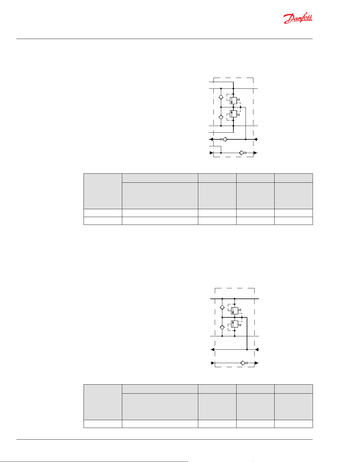
External
connection
Danfoss
steering unit
150-632.10
L
L
L
P
PP
P
R
R
R
T T
External
connection
Danfoss
steering unit
150-633.10
L L
P P
R R
T T
Technical Information
OSPB/C/F/D/L LS Steering Units, OLS Priority Valves, OSQ Flow Amplifiers
Valve Block OVPL
OVPL, 7 ports and backpressure valve
Valve block Code numbers Valve settings Weight
Connections
European version
P, T, L, R: G 1/2 - S
PP: G 1/4 - S
**
**
OVPL 24 152-1132 5 240 [3480] 2.0 [4.41]
OVPL 28 152-1115 7 280 [4061] 2.0 [4.41]
**
Spot face around port connections
Number of ports Shock valve
bar [psi]
kg [lb]
OVPL in the table below has following valve functions incorporated:
•
Check valve in P-port
•
Shock valves
•
Suction valves
OVPL, 4 ports
42 | © Danfoss | April 2021 BC152886483962en-001003
Valve block Code numbers Valve settings Weight
Connections
US version
3/4 - 16 UNF
**
O* + S
Number of ports Shock valve
bar [psi]
kg [lb]
OVPL 28 152-1133 4 280 [4061] 2.0 [4.41]
*
O-ring chamfer on port connections
Page 43

External
connection
Danfoss
steering unit
150-634.10
L L
P P
R R
T T
Technical Information
OSPB/C/F/D/L LS Steering Units, OLS Priority Valves, OSQ Flow Amplifiers
Valve Block OVPL
Valve block Code numbers Valve settings Weight
Connections
US version
3/4 - 16 UNF
**
O* + S
**
Spot face around port connections
OVPL in the table below has the following valve functions incorporated:
•
Check valve in P-port
•
Shock valves
•
Suction valves
•
Backpressure valve with by-pass to reduce stand-by pressure in neutral position.
OVPL, 4 ports and backpressure valve with by-pass
Number of ports Shock valve
bar [psi]
kg [lb]
Technical data
Valve functions
©
Danfoss | April 2021 BC152886483962en-001003 | 43
Valve block Code numbers Valve
Connections
US version
3/4 - 16 UNF
**
O* + S
OVPL 28 152-1136 4 280
*
O-ring chamfer on port connections
**
Spot face around port connections
Number of ports Shoc
Weight
setti
ngs
kg [lb]
k
valve
bar
[psi]
2.0 [4.41]
[4061
]
Common data
Common data, refer to General Steering Components Technical Information, BC152886484183.
The data below come from measurements on a representative sample of valve blocks from production.
An oil with a viscosity of 21 mm²/s [SUS] at 50°C [122°F] was used during measuring.
Page 44

200
150
100
50
0
15
10
5
0
psi bar
152-150.10
0 10 20 30 40 50 60 l/min
∆ p ∆ p
Q
p
Q
p
0 2 4 6 8 10 12 14 16 US gal/min
Technical Information
OSPB/C/F/D/L LS Steering Units, OLS Priority Valves, OSQ Flow Amplifiers
Valve Block OVPL
Valve block Max. Oil flow
l/min [US gal/min]
Max. pressure on connections
P, PP
bar [psi]
T
bar [psi]
L, R
bar [psi]
OVPL 24 100 [26.42] 190 [2756] 15 [218] 240 [3480]
OVPL 28 100 [26.42] 225 [3263] 15 [218] 280 [4061]
Shock valves
The shock valves protect the valve block and steering unit and limit maximum external forces on the
steering cylinder. The shock valves in the valve block limit the maximum pressure drop from L to T and
from R to T.
The shock valves are set at 10 l/min. [2.64 US gal/min].
The shock valves are of the direct acting type, so they react very quickly.
Setting tolerance: rated value +/- 10 bar [145 psi] , ex. 240 [3480 psi] +/- 10 bar [145 psi].
Suction valves
The suction valves ensure oil suction to avoid cavitations in the steering cylinder. To provide correct
suction, a back pressure valve must be fitted in the tank line from the steering unit.
The capacity of the suction valves can be increased by building in a back pressure in the valve block.
The curve below shows pressure drop across a suction valve
Check valve
44 | © Danfoss | April 2021 BC152886483962en-001003
The check valve protects the driver against steering wheel jerks. The check valve prevents oil from
flowing backwards into the pump line when steering against a high pressure on the cylinder side.
The check valve is built into the P connection of the valve block.
The curve below shows pressure drop across the check valve in p-connection
Page 45

60
50
40
30
20
10
0
4
3
2
1
0
psi bar
152-152.10
0 10 20 30 40 50 60 70 80 90 100 110 l/min
∆ p ∆ p
Q
p
Q
p
0 2 4 6 8 10 12 14 16 18 20 22 24 26 28 US gal/min
300
250
200
150
100
50
0
20
15
10
5
0
psi bar
152-151.10
0 10 20 30 40 50 60 70 80 90 100 l/min
∆ p ∆ p
Q
p
Q
p
0 2.5 5 7.5 10 12.5 15 17.5 20 22.5 25 US gal/min
300
250
200
150
100
50
0
20
15
10
5
0
psi bar
152-178.10
0 10 20 30 40 50 60 70 80 90 100 l/min
∆ p ∆ p
Q
p
Q
p
0 2.5 5 7.5 10 12.5 15 17.5 20 22.5 25 US gal/min
Technical Information
OSPB/C/F/D/L LS Steering Units, OLS Priority Valves, OSQ Flow Amplifiers
Valve Block OVPL
Backpressure valve
A backpressure valve increases the capacity of the suction valves.
The curve below shows pressure drop for backpressure valve without by-pass.
The curve below shows pressure drop for backpressure valve with by-pass.
©
Danfoss | April 2021 BC152886483962en-001003 | 45
Page 46
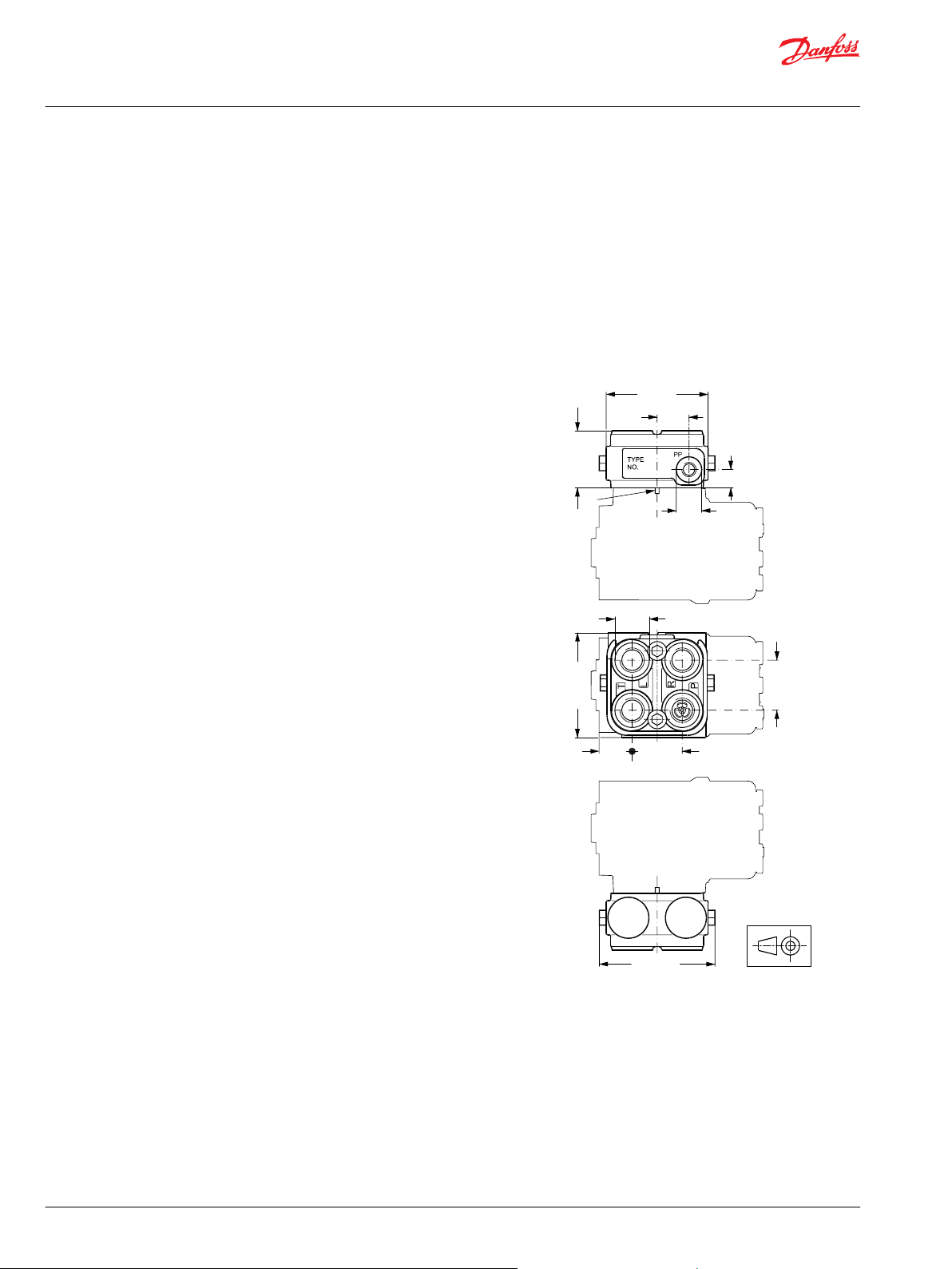
152-149.10
92 [3.62]
44 [1.73]
29 [1.14]
102 [4.02]
28 [1.10]
16 [0.63]
51 [2.01]
95 [3.74]
44 [1.73]
B
X
Y
Technical Information
OSPB/C/F/D/L LS Steering Units, OLS Priority Valves, OSQ Flow Amplifiers
Valve Block OVPL
Installation
Connection P in the valve block must be placed over the connection P in the steering unit, so OVPL is
provided with a positioning pin to fit the positioning hole in the steering unit.
The valve block is supplied inclusive of 2 mounting screws and 4 O-rings for building onto the steering
unit.
Tightening torque 65 ±5 N•m [575 ±44 lbf•in]. It is only allowed to mount OVPL blocks on steering units
with a flat port flange, no spot face is allowed.
Dimensions
OVPL, 5 ports
European version:
P, T, L and R:
G 1/2 w. spot face,
15 mm [0.59 in] deep
PP: G 1/4, w. spot face,
11,5 mm [0.45 in] deep
X: 30,2 +0,2
Y: 21,3 +/- 0,2
OVPL, 4 ports (no PP)
US version:
P, T, L and R:
3/4-16 UNF O-ring boss
15 mm [0.59 in] deep
X: 30.2 +0.2
B: Positioning pin premounted in OVPL
46 | © Danfoss | April 2021 BC152886483962en-001003
Page 47
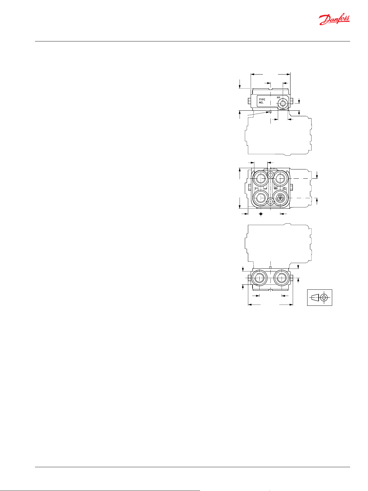
152-148.10
29 [1.14]
92 [3.62]
28 [1.10]
50 [1.97]
102 [4.02]
92 [3.62]
51 [2.01]
16 [0.63]
21.5 [0.85]
44 [1.73]
44 [1.73]
Y
X
X
B
Technical Information
OSPB/C/F/D/L LS Steering Units, OLS Priority Valves, OSQ Flow Amplifiers
Valve Block OVPL
OVPL, 7 ports
European version:
P, T, 2xL and 2xR:
G 1/2 w. spot face,
15 mm [0.59 in] deep
PP: G 1/4, w. spot face,
11.5 mm [0.45 in] deep
X: 30.2 +0.2
Y: 21.3 +/- 0.2
B: Positioning pin premounted in OVPL
©
Danfoss | April 2021 BC152886483962en-001003 | 47
Page 48

150-635.10
L L
P P
R R
T T
Technical Information
OSPB/C/F/D/L LS Steering Units, OLS Priority Valves, OSQ Flow Amplifiers
Angle Block OVR
OVR angle blocks are especially designed for applications in which pipes and/or hoses must run parallel
with the steering column axis, and where space is limited.
The valve block can be flanged onto Danfoss steering unit OSPB, OSPC, OSPD, OSPF, OSPQ and OSPL,
which have no spot face around the ports.
Use the angle block makes angle and swivel connections and pipe bends unnecessary.
The OVR connections are positioned away from the steering wheel. (see Dimensions on page 49)
Version
OVR
Code numbers and weight
Installation
OVR in the table below has no valve functions incorporated.
Angle block Code numbers Weight
Connections
European version
P, T, L, R: G 1/2
S**
OVR 152-0201 2.0 [4.41]
kg [lb]
S** : Spot face around port connections
The valve block is supplied inclusive of 2 mounting screws and 4 O-rings for building onto the steering
unit.
Tightening torque 65 ±5 N•m [575 ±44.3 lbf•in]. OVR blocks may only be mounted on steering units with
a flat port flange, (no spot facing).
For OVR blocks with other thread ore kind of valves mounted, please contact the Danfoss Sales
organization.
48 | © Danfoss | April 2021 BC152886483962en-001003
Page 49

91 [3.58]
2.5 [0.098] max.
140 [5.51]
Ø29.4 [1.158]
Ø29.0 [1.143]
38 [1.50]
106 [4.17]
15 [0.59]
r
max. 0.5 [0.20]
100 [3.94]
152-31.10
46 [1.81]
25 [0.98]
Technical Information
OSPB/C/F/D/L LS Steering Units, OLS Priority Valves, OSQ Flow Amplifiers
Angle Block OVR
Dimensions
OVR
European version:
P, T, L and R:
G 1/2, 15 mm [0.59 in] deep
©
Danfoss | April 2021 BC152886483962en-001003 | 49
Page 50

Technical Information
OSPB/C/F/D/L LS Steering Units, OLS Priority Valves, OSQ Flow Amplifiers
Priority Valves OLSA, OLS, and OLSP
Versions
Danfoss priority valves are used in steering systems with load sensing steering units. In such systems
steering always has first priority
Load sensing static priority valves
Load sensing static steering units require load sensing static priority valves. Load sensing static steering
systems have no oil flow in the LS connection when the steering unit is in neutral position.
Load sensing dynamic priority valves
Load sensing dynamic steering units require load sensing dynamic priority valves. Load sensing dynamic
steering systems have a constant oil flow in the LS connection from the priority valve to the steering unit
even when the steering unit is in neutral position.
Ports:
P = pump,
CF = controlled flow (priority oil flow),
EF = excess flow,
L = left,
R = right,
T = tank,
LS = load sensing,
PP = pilot pressure
50 | © Danfoss | April 2021 BC152886483962en-001003
Page 51

152B135.11
CF T R RLL
LS
T EFP
152B170.11
CF T R RLL
LS
T
B
A
C
EFP
Technical Information
OSPB/C/F/D/L LS Steering Units, OLS Priority Valves, OSQ Flow Amplifiers
Priority Valves OLSA, OLS, and OLSP
OLSA 40/80
The OLSA 40 and OLSA 80 “flange on” priority valves are used in load sensing steering systems, built onto
OSPC LS (OLSA) steering units.
OLSA static
OLSA dynamic
A: PP-damping orifice
B: LS-orifice
C: Dynamic-orifice
©
Danfoss | April 2021 BC152886483962en-001003 | 51
Page 52
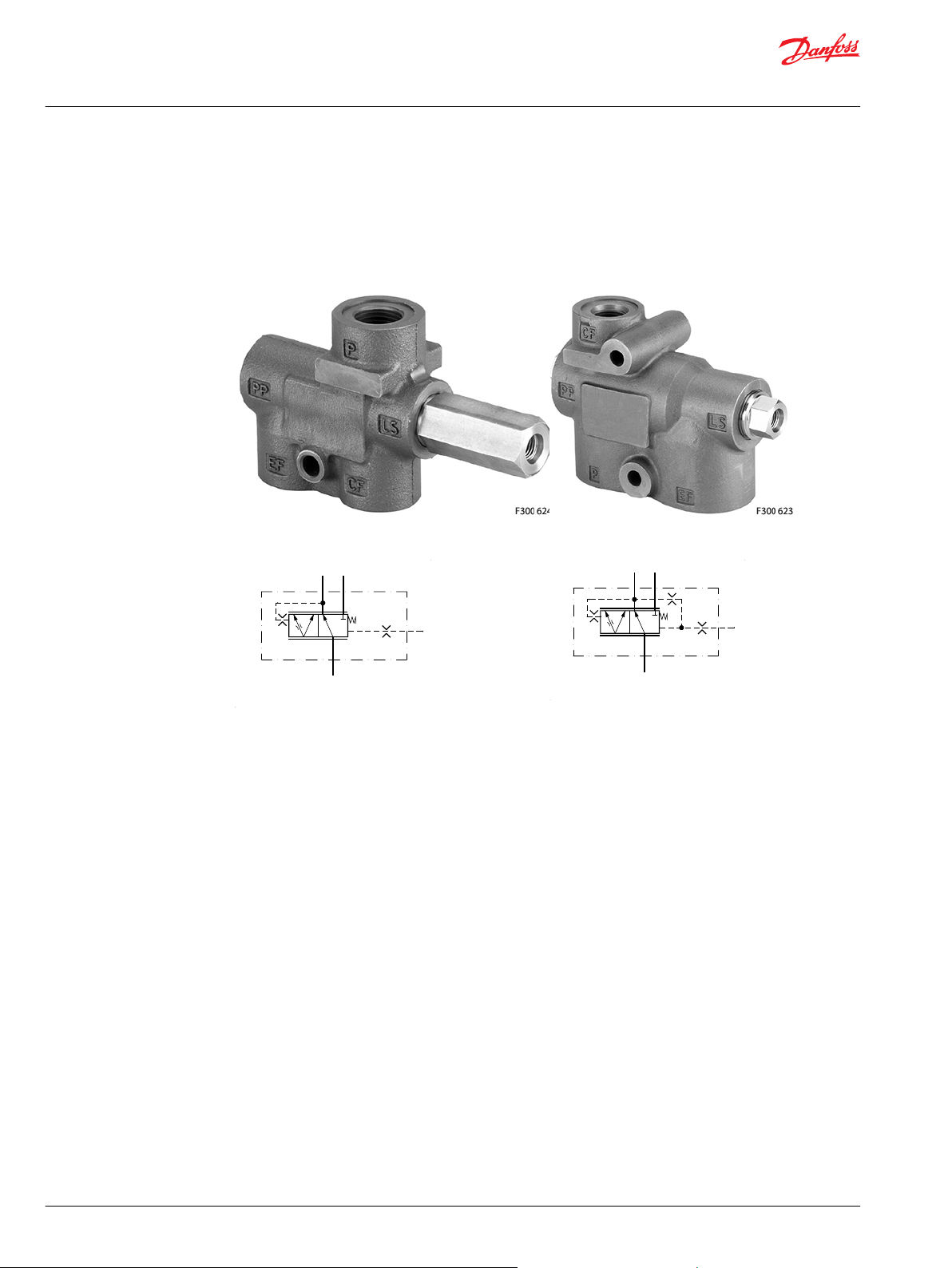
152B134.10
CF EF
LS
P
152B171.10
CF
LS
EF
P
Technical Information
OSPB/C/F/D/L LS Steering Units, OLS Priority Valves, OSQ Flow Amplifiers
Priority Valves OLSA, OLS, and OLSP
OLS 40/80 and OLS 120
The OLS 40, OLS 80, and OLS 120 “in line” priority valves are used in load sensing steering systems
together with OSPB LS, OSPC LS, OSPF LS, OSPD LS, OSPU LS and OSPL LS steering units.
OLS 40/80 OLS 120
OLS static
OLS dynamic
52 | © Danfoss | April 2021 BC152886483962en-001003
Page 53

152B137.11
CF EF LS
PP
TP
152B172.11
CF EF LS
TP
Technical Information
OSPB/C/F/D/L LS Steering Units, OLS Priority Valves, OSQ Flow Amplifiers
Priority Valves OLSA, OLS, and OLSP
OLS 160
The OLS 160 “in line” priority valve is used in load sensing steering systems together with OSPB LS, OSPC
LS, OSPF LS, OSPD LS, OSPU LS and OSPL LS steering units.
OLS 160
OLS static
OLS dynamic
OLS 160 is also available without pilot pressure relief valve.
©
Danfoss | April 2021 BC152886483962en-001003 | 53
Page 54

152B134.10
CF EF
LS
P
152B171.10
CF
LS
EF
P
Technical Information
OSPB/C/F/D/L LS Steering Units, OLS Priority Valves, OSQ Flow Amplifiers
Priority Valves OLSA, OLS, and OLSP
OLSP 80
The priority valve OLSP 80 is to be used in connection with e.g. Danfoss gear pumps type SNP and
steering units type OSPB LS, OSPC LS, OSPF LS, OSPD LS and OSPU LS in load sensing steering systems,
where maximum oil flow does not exceed 80 l/min [21.7 US gal/min].
OLSP 80 priority valves are to be flanged on gear pumps with outlet ports square flange type 35 (35 mm
pitch diameter of 4x M6 bolt holes for fixing the priority valve on pump).
OLSP
OLS 80 static
OLS 80 dynamic
54 | © Danfoss | April 2021 BC152886483962en-001003
Page 55

152B172.11
CF EF LS
TP
Technical Information
OSPB/C/F/D/L LS Steering Units, OLS Priority Valves, OSQ Flow Amplifiers
Priority Valves OLSA, OLS, and OLSP
OLS 320
The OLS 320 “in line” priority valve is used together with OSPB LS, OSPC LS, OSPF LS, OSPD LS, OSPU LS
and OSPL LS in load sensing steering systems with pump flow up to 320 l/min [84.5 USgal/min].
OLS 320 static OLS 320 dynamic
©
Danfoss | April 2021 BC152886483962en-001003 | 55
Page 56

P301 025
EF
EF
L
R
Ps
Ts
LS
LS
P
P
OLS 320
T
CL CR
EHPS
type 0
Technical Information
OSPB/C/F/D/L LS Steering Units, OLS Priority Valves, OSQ Flow Amplifiers
Priority Valves OLSA, OLS, and OLSP
OLS 320 without pilot pressure relief valve
OLS 320 is also available without pilot pressure relief valve.
EHPS steering valve has build in priority valve, but for max. pump flow 120 l/min [31.7 USgal/min] In
systems with EHPS and pump flow between 120 l/min [31.7 USgal/min] and 320 l/min [84.5 USgal/min] a
combination of EHPS and OLS 320 gives a good compact solution to reduce hosing and installation cost
compared with stand alone components. For further details of this OLS 320: look in EHPS Steering Valve
with PVE Electrical Actuation Module and OSPCX CN Steering Wheel Technical Information,
BC152886484652.
56 | © Danfoss | April 2021 BC152886483962en-001003
Page 57
Technical Information
OSPB/C/F/D/L LS Steering Units, OLS Priority Valves, OSQ Flow Amplifiers
Priority Valves OLSA, OLS, and OLSP
System sizing
The steering system pump is sized so that satisfactory performance is achieved for both steering and
working hydraulics - even at idle.
Before selecting a priority valve, consider
the type of steering unit (LS static, LS dynamic or OSPF LS dynamic)
•
the displacement of the steering unit
•
the pump flow
•
the application’s requirement for energy optimization, initial steering response time and stability, as
•
these all govern the selection for control spring pressure
whether the priority valve should have internal PP (Pilot Pressure) or external PP-connection depends
•
on the pressure drop in the pump line between the priority valve’s CF-port (Controlled Flow) and the
steering unit’s P-port. With normal hose and tube dimensions and less than 5 m distance between
priority valve and steering unit, the immediate choice is normally a priority valve with internal PP.
The following survey lists the code numbers of the priority valves that are the most frequently used in
connection with the above Danfoss steering unit types. All priority valves in the code number tables,
except OLS 160 static, have internal PP connection. OLS 160 static in the code number table all have
external PP connection.
Code numbers and weights
OLS/OLSA static priority valves for load sensing static steering units
OLSA 40 static and OLSA 80 static
Priority valve Code Numbers Control spring
Connections
European version
T,R,L: G 3/8
P, EF: G 1/2
OLSA 40 152B0001 - 4 [58] 2.1 [4.63]
OLSA 40 152B0002 152B0122 7 [101.5] 2.1 [4.63]
OLSA 40 152B0003 152B0124 10 [145] 2.1 [4.63]
OLSA 80 152B0016 152B0019 4 [58] 2.1 [4.63]
OLSA 80 152B0017 152B0020 7 [101.5] 2.1 [4.63]
OLSA80 152B0015 152B0125 10 [145] 2.1 [4.63]
US version
T, R, L: 9/16 - 18 UNF
P, EF: 7/8 - 14 UNF
pressure
bar [psi]
Weight
kg [lb]
OLS 40 static and OLS 80 static
Priority valve Code Numbers Control spring
Connections
European version
LS: G 1/4
P, EF, CF: G 1/2
OLS 40 152B0231 152B0237 4 [58] 1.0 [2.2]
OLS 40 152B0232 152B0238 7 [101.5] 1.0 [2.2]
OLS 40 152B0233 152B0253 10 [145] 1.0 [2.2]
OLS 80 152B0261 152B0267 4 [58] 1.0 [2.2]
US version
LS: 7/16 - 20 UNF
CF: 3/4 - 16 UNF
P, EF: 7/8 - 14 UNF
pressure
bar [psi]
Weight
kg [lb]
©
Danfoss | April 2021 BC152886483962en-001003 | 57
Page 58

Technical Information
OSPB/C/F/D/L LS Steering Units, OLS Priority Valves, OSQ Flow Amplifiers
Priority Valves OLSA, OLS, and OLSP
OLS 40 static and OLS 80 static (continued)
Priority valve Code Numbers Control spring
Connections
European version
LS: G 1/4
P, EF, CF: G 1/2
OLS 80 152B0262 152B0268 7 [101.5] 1.0 [2.2]
OLS 80 152B0263 152B0280 10 [145] 1.0 [2.2]
OLS/OLSA static priority valves for load sensing statics steering units
OLS 120 static
Priority valve Code Numbers Control spring
Connections
European version
LS: G 1/4
CF: G 1/2
P, EF: G 3/4
OLS 120 152B2232 152B2238 7 [101.5] 2.1 [4.63]
OLS 120 152B2233 152B2239 10 [145] 2.1 [4.63]
US version
LS: 7/16 - 20 UNF
CF: 3/4 - 16 UNF
P, EF: 7/8 - 14 UNF
US version
LS: 7/16 -20 UNF
CF: 3/4 - 16 UNF
P, EF: 1 1/16 - 12 UNF
pressure
bar [psi]
pressure
bar [psi]
Weight
kg [lb]
Weight
kg [lb]
OLS 160 static
Priority valve Code numbers Control
Connections
European version
LS, PP, T: G 1/4
CF: G 1/2
P, EF: G 3/4
OLS 160 152B1005 152B1085 7 [101.5] 170 [2465] 4.4 [9.7]
OLS 160 152B1006 152B1086 10 [145] 170 [2465] 4.4 [9.7]
US version
LS, PP, T: 7/16 -20 UNF
CF: 3/4 - 16 UNF
P, EF: 1 1/16 - 12 UNF
spring
pressure
bar [psi]
Pilot
pressure
relief
valve
bar [psi]
Weight
kg [lb]
OLS/OLSA dynamic priority valves for load sensing dynamic steering units
OLSA 40 dynamic and OLSA 80 dynamic for OSPC LS dynamic
Priority valve Code numbers Control spring
Connections
European version
T,R,L: G 3/8
P/EF: G 1/2
OLSA 40 152B8001 - 4 [58] 2.1 [4.63]
OLSA 40 152B8041 152B8042 7 [101.5] 2.1 [4.63]
OLSA 40 152B8046 152B8043 10 [145] 2.1 [4.63]
OLSA 80 152B8047 - 4 [58] 2.1 [4.63]
OLSA 80 152B8048 152B8044 7 [101.5] 2.1 [4.63]
OLSA 80 152B8049 152B8045 10 [145] 2.1 [4.63]
US version
T,R,L: 9/16 - 18 UNF
P/EF: 7/8 - 14 UNF
pressure
bar [psi]
Weight
kg [lb]
58 | © Danfoss | April 2021 BC152886483962en-001003
Page 59

Technical Information
OSPB/C/F/D/L LS Steering Units, OLS Priority Valves, OSQ Flow Amplifiers
Priority Valves OLSA, OLS, and OLSP
OLS/OLSA dynamic priority valves for load sensing dynamic steering units
OLS 40 dynamic and OLS 80 dynamic for OSPB, OSPC, OSPD and OSPL LS dynamic
Priority valve Code numbers Control spring
Connections
European version
LS: G 1/4
P, EF, CF: G 1/2
OLS 40 152B8231 - 4 [58] 1.0 [2.20]
OLS 40 152B8232 152B8253 7 [101.5] 1.0 [2.20]
OLS 40 152B8233 152B8254 10 [145] 1.0 [2.20]
OLS 80 152B8261 - 4 [58] 1.0 [2.20]
OLS 80 152B8256 152B8268 7 [101.5] 1.0 [2.20]
OLS 80 152B8257 152B8260 10 [145] 1.0 [2.20]
OLS 80 dynamic with low pressure drop (P-EF) spool for OSPB, OSPC, OSPD and OSPL LS dynamic
Priority valve Code numbers Control spring
Connections
European version
LS: G 1/4
P, EF, CF: G 1/2
OLS 80 152B8259 7 [101.5] 1.0 [2.20]
US version
LS: 7/16 - 20 UNF
CF: 3/4 - 16 UNF
P, EF: 7/8 - 14 UNF
pressure
bar [psi]
pressure
bar [psi]
Weight
kg [lb]
Weight
kg [lb]
OLS 120 dynamic for OSPB, OSPC, OSPD and OSPL LS dynamic
Priority valve Code numbers Control spring
Connections
European version
LS: G 1/4
CF: G 1/2
P, EF: G 3/4
OLS 120 152B8132 152B8143 7 [101.5] 2.1 [4.63]
OLS 120 152B8133 152B8144 10 [145] 2.1 [4.63]
US version
LS: 7/16 -20 UNF
CF: ¾ - 16 UNF
P, EF: 1 1/16 - 12 UNF
pressure
bar [psi]
Weight
kg [lb]
OLS 160 dynamic for OSPB, OSPC, OSPD and OSPL LS dynamic
Priority valve Code numbers Control
Connections
European version
LS, T: G 1/4
CF: G 1/2
P, EF: G 3/4
OLS 160 152B8159 152B8154 7 [101.5] 170 [2465] 4.4 [9.7]
OLS 160 152B8160 152B8155 10 [145] 170 [2465] 4.4 [9.7]
OLS 160 152B8105 - 12 [174] 170 [2465] 4.4 [9.7]
OLS 160 152B8161 152B8156 7 [101.5] 210 [3045] 4.4 [9.7]
OLS 160 152B8162 152B8157 10 [145] 210 [3045] 4.4 [9.7]
US version
LS, T: 1/16 -20 UNF
CF: 3/4 - 16 UNF
P, EF: 1 1/16 - 12 UNF
spring
pressure
bar [psi]
Pilot
pressure
relief
valve
bar [psi]
Weight
kg [lb]
©
Danfoss | April 2021 BC152886483962en-001003 | 59
Page 60
Technical Information
OSPB/C/F/D/L LS Steering Units, OLS Priority Valves, OSQ Flow Amplifiers
Priority Valves OLSA, OLS, and OLSP
OLS dynamic priority valves for OSPF LS and OSPU LS dynamic steering units
OLS 40 dynamic and OLS 80 dynamic
Priority valve Code numbers Control spring
Connections
European version
LS: G 1/4
P, EF, CF: G 1/2
OLS 40 152B8031 10 [145] 1.0 [2.20]
OLS 80 152B8258 7 [101.5] 1.0 [2.20]
OLS 120 dynamic
Priority valve Code numbers Control spring
Connections
European version
LS: G 1/4, CF: G 1/2
P, EF, CF: G 3/4
OLS 120 152B8147 7 [101.5] 2.1 [4.63]
pressure
bar [psi]
pressure
bar [psi]
Weight
kg [lb]
Weight
kg [lb]
OLS 160 dynamic
Priority valve Code numbers Control
Connections
European version
LS: G 1/4, CF: G 1/2
P, EF, CF: G 3/4
OLS 160 152B8158 7 [101.5] none 4.4 [9.7]
OLS 160 152B8113 10 [145] none 4.4 [9.7]
spring
pressure
bar [psi]
Pilot pressure
relief valve
bar [psi]
Weight
kg [lb]
OLSP static and dynamic
Priority valve Code numbers Control
Connections
European version
LS: G¼
CF: G 3/8
EF: G ½
OLSP 80 static 152B5002 4 [58] 1.0 [2.2]
OLSP 80 dynamic 152B5200 7 [101.5] 1.0 [2.2]
OLSP 80 dynamic for OSPF and
OSPU
152B5201 7 [101.5] 1.0 [2.2]
spring
pressure
bar [psi]
Weight
kg [lb]
60 | © Danfoss | April 2021 BC152886483962en-001003
Page 61
Technical Information
OSPB/C/F/D/L LS Steering Units, OLS Priority Valves, OSQ Flow Amplifiers
Priority Valves OLSA, OLS, and OLSP
OLS 320 dynamic in-line/stand alone with pilot pressure relief valve, black painted
Priority valve Code numbers Control
Connections
European version
LS, T: G¼
CF: G ½
P, EF: G 1
OLS 320 11006593 7 [101.5] 170 [2465] 5.9 [13.0]
OLS 320 dynamic in-line/stand alone without pilot pressure relief valve, black painted
Priority valve Code numbers Control spring
Connections
US version
LS: 7/16 - 20 UNF
CF: 11/16 - 12 UN
P, EF: 15/16 - 12 UN
OLS 320 11007475 10 [145] 5.9 [13.0]
spring
pressure
bar [psi]
Pilot
pressure
relief valve
bar [psi]
pressure
bar [psi]
Weight
kg [lb]
Weight
kg [lb]
OLS 320 for EHPS: look in EHPS Steering Valve with PVE Electrical Actuation Module and OSPCX CN Steering
Wheel Technical Information, BC152886484652
If you require other port connections, other control spring pressure and/or other PP connection, go to the
survey under System sizing on page 57, and tick off the desired specifications, then consult the Danfoss
Sales Organization.
©
Danfoss | April 2021 BC152886483962en-001003 | 61
Page 62

Technical Information
OSPB/C/F/D/L LS Steering Units, OLS Priority Valves, OSQ Flow Amplifiers
Priority Valves OLSA, OLS, and OLSP
Specification table for non catalogue numbers of Danfoss Priority Valves
Your
company
Your
application
Priority valve
type
Load sensing
type
Spool type Standard Low pressure drop, P-EF (only OLS/OLSA 80 dynamic) No CF cut-off (only for OLS 320 for flanging on EHPS)
Control
spring, bar
PP
connection
Ports,
OLSA
Ports,
OLS 40/80
Name Vehicle Potential, pcs/year Completed by Date
Pump flow to OLS/OLSA at idle, l/min [USgal/min] Pump flow to OLS/OLSA at max. engine speed, l/min [USgal/min]
OLSA 40 OLSA 80 OLS 40 OLS 80 OLS 120 OLS 160 OLSP 80 OLS 320 in-line
Static Dynamic Dynamic for OSPF and OSPU steering unit
4 (only OLS 80, 120, 160, OLSP
80)
Internal External (not OLSP)
G: P, EF: G½ - S**
T, L, R: G3/8 - S**
P, CF, EF: G½ - S**
G: LS: G½ - S**
5.5 (only OLS/OLSA 40/80) 7 10 12 (only OLS 160) 16 (only OLS
160)
Metric 1: P, EF, T, L, R:
M18 • 1.5 -O*** +S**
P, EF: M22 • 1.5 - O*** +S**
Metric: CF: M18 • 1.5 - O*** +S**
LS: M12 • 1.5 - O*** +S**
Metric 2: P, EF: M22 • 1.5 - O***
+S**
T, L, R: M18 • 1.5 - O*** +S**
P, EF: 7/8 - 14 UNF - O***
UNF: CF: 3/4 - 16 UNF - O***
LS: 7/16 - 20 UNF - O***
UNF: P, EF: 7/8 - 14 UNF - O***
T, L, R : 9/16 - 18 UNF - O***
Ports,
OLS 120
Ports,
OLS 160
Ports, OLSP
80 (P: square
flange 35)
Ports, OLS
320 in-line
RV-bar
OLS 160
OLS 320
Unit black
painted
P, EF: G¾ - S**
G: CF: G½ - S**
LS, PP: G¼ - S**
P, EF: G¾ - S**
G 1: CF: G½ - S**
LS, PP, T: G¼ - S**
EF: G½ - S**
G: CF: G3/8 - S**
LS: G¼ - S**
P, EF: G1 - S**
G: CF: G½ - S**
LS, PP: G¼ - S**
80 90 100 110 120 140 170 190 200 210 Other settings No relief valve
Yes No
P, EF: G1 - S**
G 2: CF: G¾ - S**
LS, PP, T: G¼ - S**
P, EF: M27 • 2 - O*** +S**
Metric: CF: M18 • 1.5 - O*** +S**
LS: M12 • 1.5 - O*** +S**
P, EF: 11/16 - 12 UN - O***
UNF 1: CF: 3/4 - 16 UNF - O***
LS, PP, T: 7/16 - 20 UNF - O***
EF: M22 • 1.5 - S**
Metric: CF: M18 • 1.5 - S**
LS: M12 • 1.5 - S**
P, EF: 1 5/16 - 12 UN - O***
UNF 1: CF: 3/4 - 16 UNF - O***
LS, PP, T: 7/16 - 20 UNF - O***
P, EF: 11/16 - 14 UNF - O***
UNF: CF: 3/4 - 16 UNF - O***
LS: 7/16 - 20 UNF - O***
P, EF:15/16 - 12 UN - O***
UNF 2: CF: 7/8 - 14 UNF - O***
LS, PP, T: 7/16 - 20 UNF - O***
EF: 7/8 - 14 UNF - O***
UNF: CF: 3/4 - 16 UNF - O***
LS : 7/16 - 20 UNF - O***
P, EF: 1 5/16 - 12 UN - O***
UNF 2: CF: 1 1/16 - 12 UNF - O***
LS, PP, T: 7/16 - 20 UNF - O***
bar
Ports: PP-port only exists when external PP connection is used. T-port only exists for OLS 160 and OLS 320
with integrated pilot pressure relief valve (RV)
O*: O-ring chamfer on port connections
62 | © Danfoss | April 2021 BC152886483962en-001003
Page 63

200
175
150
125
100
75
50
25
0
14
12
10
8
6
4
2
0
psi bar
152B139.11
0 5 10 15 20 25 30 35 40 l/min
P-EF P-EF
Q
p
Q
p
0 1 2 3 4 5 6 7 8 9 10 US gal/min
4 bar
58 psi
7 bar
102 psi
10 bar
145 psi
min
Technical Information
OSPB/C/F/D/L LS Steering Units, OLS Priority Valves, OSQ Flow Amplifiers
Priority Valves OLSA, OLS, and OLSP
S**: Spot face around port connections
An alternative way to specify a variant is to state an existing code number and add the modifications, you
would like to have implemented in the basic steering unit.
Code number of basic steering unit: __________________________________________________
Requested modifications:
_______________________________________________________________________
Technical data
Max. pressure on connections
Priority
valve
Rated flow
to Pconnection
l/min [US
Max. pressure on connections
P, EF CF L, R LS T PP
bar [psi] bar [psi] bar [psi] bar [psi] bar [psi] bar [psi]
gal/min]
OLSA 40 40 [10.57] 250 [3625] 240 [3480] 280 [4061] 240 [3480] 20 [290] - OLSA 80 80 [21.13] 250 [3625] 240 [3480] 280 [4061] 240 [3480] 20 [290] - OLS 40 40 [10.57] 280 [4061] 240 [3480] - - 240 [3480] - - 210 [3045]
OLS 80 80 [21.13] 280 [4061] 240 [3480] - - 240 [3480] - - 210 [3045]
OLS 120 120 [31.70] 300 [4351] 240 [3480] - - 240 [3480] - - 210 [3045]
OLS 160 160 [42.27] 350 [5076] 240 [3480] - - 240 [3480] 15 [217] 210 [3045]
OLSP 80 80 [21.13] 280 [4061] 240 [3480] - - 240 [3480] - - - OLS 320 320 [84.54] 300 [4351] 280 [4061] - - 280 [4061] 40 [580] 280 [4061]
Pressure drop in priority valves
This data comes from measurements on a representative sample of priority valves from production. Oil
with viscosity of 21 mm²/s at 50 °C [102 SUS at 122 °F] was used during measuring. Measurement made
when pressure on the LS connection is zero (steering unit in neutral position). The minimum curves apply
when the pressure on the EF connection is higher than the actual control spring pressure. The curves for
control spring pressure of 4 , 7, 10 or 12 bar [58, 101, 145 or 174 psi] apply when pressure on the EF
connection is zero.
Pressure drop P-EF for static priority valves
OLSA/OLS 40
©
Danfoss | April 2021 BC152886483962en-001003 | 63
Page 64

psi bar
0 10 20 30 40 50 60 70 80 l/min
0 2 4 6 8 10 12 14 16 18 20 US gal/min
10 bar
145 psi
7 bar
102 psi
4 bar
58 psi
min.
152B80.11
225
200
175
150
125
100
75
50
25
0
16
14
12
10
8
6
4
2
0
P-EF P-EF
Q
p
Q
p
225
200
175
150
125
100
75
50
25
0
16
14
12
10
8
6
4
2
0
psi bar
152B165.11
0 10 20 30 40 50 60 70 80 90 100 110 120 l/min
P-EF P-EF
Q
p
Q
p
0 5 10 15 20 25 30 US gal/min
7 bar
102 psi
10 bar
145 psi
min
Technical Information
OSPB/C/F/D/L LS Steering Units, OLS Priority Valves, OSQ Flow Amplifiers
Priority Valves OLSA, OLS, and OLSP
OLSA/OLS 80
OLS 120
64 | © Danfoss | April 2021 BC152886483962en-001003
Page 65

275
250
225
200
175
150
125
100
75
50
25
0
20
18
16
14
12
10
8
6
4
2
0
psi bar
152B166.10
0 10 20 30 40 50 60 70 80 90 100 110 120 130 140 150 160 l/min
P-EF P-EF
Q
p
Q
p
0 5 10 15 20 25 30 35 40 US gal/min
7 bar
102 psi
10 bar
145 psi
12 bar
174 psi
min
225
200
175
150
125
100
75
50
25
0
16
14
12
10
8
6
4
2
0
psi bar
152B174.10
0 5 10 15 20 25 30 35 40 l/min
P-EF P-EF
Q
p
Q
p
0 1 2 3 4 5 6 7 8 9 10 US gal/min
7 bar
102 psi
10 bar
145 psi
4 bar
58 psi
min
Technical Information
OSPB/C/F/D/L LS Steering Units, OLS Priority Valves, OSQ Flow Amplifiers
Priority Valves OLSA, OLS, and OLSP
OLS 160
Pressure drop P-EF for dynamic priority valves
OLSA/OLS 40
©
Danfoss | April 2021 BC152886483962en-001003 | 65
Page 66

275
250
225
200
175
150
125
100
75
50
25
0
20
18
16
14
12
10
8
6
4
2
0
psi bar
152B175.10
0 10 20 30 40 50 60 70 80 l/min
P-EF P-EF
Q
p
Q
p
0 2 4 6 8 10 12 14 16 18 20 US gal/min
7 bar
102 psi
10 bar
145 psi
4 bar
58 psi
min
min
A
B
A+B
A+B
A+B
275
250
225
200
175
150
125
100
75
50
25
0
20
18
16
14
12
10
8
6
4
2
0
psi bar
152B176.10
0 10 20 30 40 50 60 70 80 90 100 110 120 l/min
P-EF P-EF
Q
p
Q
p
0 5 10 15 20 25 30 US gal/min
7 bar
102 psi
7 bar
102 psi
10 bar
145 psi
min
A
A
B
A+B
Technical Information
OSPB/C/F/D/L LS Steering Units, OLS Priority Valves, OSQ Flow Amplifiers
Priority Valves OLSA, OLS, and OLSP
OLSA/OLS 80
A: OLS/OLSA 80 Dynamic for OSPB, OSPC, OSPF, OSPD, OSPQ, OSPL LS Dynamic
B: OLS/OLSA 80 Dynamic with low pressure drop (P-EF) spool for OSPB, OSPC, OSPD, OSPQ, OSPL LS
Dynamic
OLS 120
66 | © Danfoss | April 2021 BC152886483962en-001003
A: OLS 120 Dynamic for OSPB, OSPC, OSPD, OSPQ, OSPL LS Dynamic
B: OLS 120 Dynamic for OSPF LS Dynamic and for OSPU LS Dynamic
Page 67

450
400
350
300
250
200
150
100
50
0
32
28
24
20
16
12
8
4
0
psi bar
152B177.10
0 10 20 30 40 50 60 70 80 90 100 110 120 130 140 150 160 l/min
P-EF P-EF
Q
p
Q
p
0 5 10 15 20 25 30 35 40 US gal/min
7 bar
102 psi
7 bar
102 psi
10 bar
145 psi
12 bar
174 psi
min
A
A
A
B
A+B
175
150
125
100
75
50
25
0
12
10
8
6
4
2
0
psi bar
152-181.10
0 10 20 30 40 50 60 70 80 l/min
P-EF P-EF
Q
p
Q
p
0 2 4 6 8 10 12 14 16 18 US gal/min
7 bar
102 psi
4 bar
58 psi
min
Technical Information
OSPB/C/F/D/L LS Steering Units, OLS Priority Valves, OSQ Flow Amplifiers
Priority Valves OLSA, OLS, and OLSP
OLS 160
A: OLS 160 Dynamic for OSPB, OSPC, OSPD, OSPL LS Dynamic
B: OLS 160 Dynamic for OSPF LS and for OSPU LS Dynamic
Pressure drop P-EF for OLSP static priority valves
OLSP 80
©
Danfoss | April 2021 BC152886483962en-001003 | 67
Page 68

175
150
125
100
75
50
25
0
12
10
8
6
4
2
0
psi bar
152-182.10
0 10 20 30 40 50 60 70 80 l/min
P-EF P-EF
Q
p
Q
p
0 2 4 6 8 10 12 14 16 18 US gal/min
4 bar
58 psi
min
7 bar
102 psi
B
A
A
A+B
250
225
200
175
150
125
100
75
50
25
0
18
16
14
12
10
8
6
4
2
0
psi bar
152B185.10
0 20 40 60 80 100 120 140 160 180 200 220 240 260 280 300 320 l/min
P-EF P-EF
Q
p
Q
p
0 5 10 15 20 25 30 35 40 45 50 55 60 65 70 75 80 85 US gal/min
7 bar
102 psi
10 bar
145 psi
min.
Technical Information
OSPB/C/F/D/L LS Steering Units, OLS Priority Valves, OSQ Flow Amplifiers
Priority Valves OLSA, OLS, and OLSP
Pressure drop P-EF for OLSP dynamic priority valves
A: OLSP 80 Dynamic for OSPB, OSPC, OSPD, OSPL LS Dynamic
B: OLSP 80 Dynamic for OSPF LS and for OSPU LS Dynamic
Pressure drop P-EF for OLS 320 static priority valves
OLS 320
68 | © Danfoss | April 2021 BC152886483962en-001003
Page 69

450
400
350
300
250
200
150
100
50
0
30
25
20
15
10
5
0
psi bar
152B186.10
0 20 40 60 80 100 120 140 160 180 200 220 240 260 280 300 320 l/min
P-EF P-EF
Q
p
Q
p
0 5 10 15 20 25 30 35 40 45 50 55 60 65 70 75 80 85 US gal/min
7 bar
102 psi
10 bar
145 psi
min
2800
2700
2600
2500
2400
2300
2200
0
190
180
170
160
150
0
psi bar
152B141.11
0 10 20 30 40 50 60 70 80 90 100 110 120 130 140 150 160 l/min
P-T P-T
Q
p
Q
p
0 5 10 15 20 25 30 35 40 US gal/min
Technical Information
OSPB/C/F/D/L LS Steering Units, OLS Priority Valves, OSQ Flow Amplifiers
Priority Valves OLSA, OLS, and OLSP
Pressure drop P-EF for OLS 320 dynamic priority valves
OLS 320
OLS 160 and OLS 320, pilot pressure relief valve (P - T, Qp) characteristics
OLS 160 and OLS 320 with pilot pressure relief valves are used in connection with Danfoss steering units
without pilot pressure relief valve, normally steering unit type OSPL. The pilot pressure relief valve
protects the steering unit against excessive pressure. The pilot pressure relief valve in OLS 160/320
operates with the priority valve spool in the OLS 160/320 to limit the maximum steering pressure P-T
measured across the steering unit ports.
OLS 160:The pilot pressure relief valve is set when an oil flow of 80 l/min [21 US gal/min] is supplied to
OLS 160.
OLS 320:The pilot pressure relief valve is set when an oil flow of 40 l/min [11 US gal/min] is supplied to
OLS 320.
OLS 160 and OLS 320: Setting tolerance: rated value +10 bar [145 psi]
OLS 160
©
Danfoss | April 2021 BC152886483962en-001003 | 69
Page 70

3000
2900
2800
2700
2600
2500
2400
2300
2200
2100
0
210
200
190
180
170
160
150
0
psi bar
152B187.10
0 40 80 120 160 200 240 280 320 l/min
HP-HT HP-HT
Q
p
Q
p
0 10 20 30 40 50 60 70 80 US gal/min
Technical Information
OSPB/C/F/D/L LS Steering Units, OLS Priority Valves, OSQ Flow Amplifiers
Priority Valves OLSA, OLS, and OLSP
OLS 320
Qp = Pump flow
70 | © Danfoss | April 2021 BC152886483962en-001003
Page 71

YY
R L
44 [1.73]
X
EF
L
R/CF
EF
P
T
7 [0.28]
20 [0.79]
X
Y
T
P
152B81.12
44 [1.73] 29 [1.14]
55 [2.17]
120 [4.72]
87 [3.43]
87 [3.43]
20 [0.79]
40 [1.57]
76 [2.99]
29 [1.14]
Technical Information
OSPB/C/F/D/L LS Steering Units, OLS Priority Valves, OSQ Flow Amplifiers
Priority Valves OLSA, OLS, and OLSP
Dimensions
OLSA
©
Danfoss | April 2021 BC152886483962en-001003 | 71
Page 72

Technical Information
OSPB/C/F/D/L LS Steering Units, OLS Priority Valves, OSQ Flow Amplifiers
Priority Valves OLSA, OLS, and OLSP
European version: US version:
P, EF:
G 1/2 w. spot face
14 mm [0.55 in] deep
x = 34 mm [1.34 in],
max. 1,5 mm [0.06 in] deep or M18 x 1.5 ISO 6149
14.5 mm [0.57 in] deep
x = 29 mm [1.14 in],
max. 1.5 mm [0.06 in] deep or M22 x 1.5 ISO 6149,
15.5 mm [0.61 in] deep
x = 34 mm [1.34 in],
max. 1.5 mm [0.06 in] deep
T, L, R:
G 3/8 w. spot face
12 mm [0.47 in] deep
y = 34 mm [1.34 in],
max. 1.5 mm [0.06 in] deep or M18 x 1.5 ISO 6149,
15 mm [0.59 in] deep
y = 29 mm [1.14 in],
max. 1.5 mm [0.06 in] deep
P, EF:
7/8-14 UNF O-ring boss
16.7 mm [0.66 in] deep
x = 34 mm [1.34 in],
max. 1.5 mm [0.06 in] deep
T, L, R:
9/16 - 18 UNF O-ring boss
12.7 mm [0.50 in] deep
y = 25 mm [0.98 in],
max. 1.5 mm [0.06 in] deep
72 | © Danfoss | April 2021 BC152886483962en-001003
Page 73

Z
42 [1.65]
X
X
Y
LS
CF
EF
P
Ø8.9 [0.350]
Ø8.5 [0.335]
PP
152B136.11
19.7 [0.776]
41 [1.61]
139 [5.47]
19.7 [0.776]
25 [0.98]
40.3 [1.587]
40.3 [1.587]
22 [0.87]
20.3 [0.799]
39 [1.54]
Technical Information
OSPB/C/F/D/L LS Steering Units, OLS Priority Valves, OSQ Flow Amplifiers
Priority Valves OLSA, OLS, and OLSP
OLS 40, OLS 80
European version: US version:
P, EF:
G 1/2 w. spot face
15 mm [0.59 in] deep
x = 29 mm [1.14 in],
max. 1.5 mm [0.06 in] deep
or M22 x 1.5 ISO 6149
15 mm [0.59 in] deep,
x = 34 mm [1.34 in],
P, EF:
7/8 - 14 UNF O-ring boss
15 mm [0.59 in] deep
x = 34 mm [1.14 in],
max. 1.3 [0.05] deep
max. 1 mm [0.04 in] deep
CF:
G 1/2 w. spot face
14 mm [0.55 in]deep
y = 29 mm [1.14 in],
max. 1.5 mm [0.06 in] deep or M18 x 1,5 ISO 6149
12 mm [0.47 in] deep,
y = 29 mm [1.14 in],
CF:
3/4-16 UNF O-ring boss
14.3 mm [0.56 in] deep
y = 30 mm [1.18 in],
max. 1.3 mm [0.05 in] deep
max. 1 mm [0.04 in] deep
LS:
G 1/4 w. spot face
12.5 mm [0.49 in] deep
z = 21mm [0.83 in],
©
Danfoss | April 2021 BC152886483962en-001003 | 73
LS:
7/16-20 UNF O-ring boss
12.5 mm [0.49 in] deep
z = 21 mm [0.83 in],
Page 74

Technical Information
OSPB/C/F/D/L LS Steering Units, OLS Priority Valves, OSQ Flow Amplifiers
Priority Valves OLSA, OLS, and OLSP
max. 1 mm [0.04 in] deep or M12 x 1,5 ISO 6149
12,5 mm [0.49 in] deep,
z = 22 mm [0.86 in]
0 mm deep
max. 1 mm [0.04 in] deep
74 | © Danfoss | April 2021 BC152886483962en-001003
Page 75

Z Z
10 [0.39]
X X
LS
CF
EF
P
38.4 [1.512]
Y
PP
152B173.11
114 [4.49]
18.7 [0.736]
24 [0.94]
56 [2.20]
Ø9.1 [0.358]
Ø8.7 [0.343]
Ø9.1 [0.358]
Ø8.7 [0.343]
96 [3.78]
53 [2.09]
66 [2.60]
80 [3.15]
140 [5.51]
Technical Information
OSPB/C/F/D/L LS Steering Units, OLS Priority Valves, OSQ Flow Amplifiers
Priority Valves OLSA, OLS, and OLSP
OLS 120
©
Danfoss | April 2021 BC152886483962en-001003 | 75
European version: US version:
P, EF:
G 3/4 w. spot face
x = 42 mm [1.65 in],
max. 2.5 mm [0.10 in] deep or M27 x 2 ISO 6149
x = 40 mm [1.57 in],
max. 2.5 mm [0.10 in] deep
CF:
G 1/2 w. spot face
y = 34 mm [1.34 in],
max. 2.5 mm [0.10 in] deep or M18 x 1.5 ISO 6149
y = 29 mm [1.14 in],
max. 2.5 mm [0.10 in] deep
LS, PP:
G 1/4 w. spot face
12 mm [0.47 in] deep
z = 19 mm [0.75 in]
0 mm deep
or M12 x 1,5 ISO 6149
11,5 mm [0.45 in] deep,
z = 19 mm [0.75 in]
0 mm deep
P, EF:
1 1/16 - 12 UN O-ring boss
x = 41mm [1.61 in],
max. 1.5 mm [0.06 in] deep
CF:
3/4 - 16 UNF O-ring boss
y = 30 mm [1.18 in],
max. 1.5 mm [0.06 in] deep
LS, PP:
7/16 - 20 UNF O-ring boss
11.5 mm [0.45 in] deep
z = 19 mm [0.75 in] 0 mm deep
Page 76

178 [7.01]
75 [2.95]
33 [1.26]
25 [0.98]
32 [1.26]
ø8.9 ± 0.2 [ø0.35 ± 0.01]
35 [1.38] 63 [2.48]
130 [5.12]
ø8.9 ± 0.2 [ø0.35 ± 0.01]
32 [1.26]
61.3 [2.41]
124 [4.88]
33 [1.30]
66 [2.60]
Z
U
X
X
Y
Technical Information
OSPB/C/F/D/L LS Steering Units, OLS Priority Valves, OSQ Flow Amplifiers
Priority Valves OLSA, OLS, and OLSP
OLS 160
European version: US version:
P, EF:
G 3/4 w. spot face
x = 42 mm [1.65 in],
max. 2.5 mm [0.10 in] deep or G 1 w. spot face
x = 47 mm [1.85 in],
max 2.5 mm [0.10 in] deep
CF:
G 1/2 w. spot face
y = 34 mm [1.34 in],
max. 2.5 mm [0.10 in] deep or G 3/4 w. spot face
y = 38 mm [1.50 in],
max. 2.5 mm [0.10 in] deep
LS, PP, T:
G 1/4 w. spot face
12 mm [0.47 in] deep
z = 22.8 mm [0.89 in],
max. 1 mm [0.04 in]deep
u = 25 mm [0.98 in]
max. 1.5 mm [0.06 in] deep
P, EF:
1 1/16-12 UNF O-ring boss
x = 41 mm [1.61 in],
max. 2.5 mm [0.10 in] deep or 1 5/16 - 12 UNF O-ring boss
x = 49 mm [1.93 in],
max. 2.5 mm [0.10 in] deep
CF:
3/4-16 UNF O-ring boss
y = 32 mm [1.26 in],
max. 2.5 mm [0.10 in] deep
7/8 - 14 UNF O-ring boss
y = 30 mm [1.18 in],
max. 2.5 mm [0.10 in] deep
LS, PP, T:
7/16 - 20 UNF O-ring boss
11.5 mm [0.45 in] deep
z = 22,8 mm [0.89 in],
max. 1.5 mm [0.06 in] deep
u = 21 mm [0.83 in],
max. 1.6 mm [0.06 in] deep
76 | © Danfoss | April 2021 BC152886483962en-001003
Page 77

152-180.11
20 [0.89]
25 [0.98]
32 [1.26]
38 [1.50]
84 [3.31]
33 [1.30]
24.7 [0.972]
Ø24.4 [0.961]
1.88 [0.74] deep
52 [2.05]
19.5 [0.768]
24 [0.94]
38 [1.50]
31.2 [1.228]
43.5 [1.713]
91 [3.58]
Ø11 [0.04]
Ø6.5 [0.26]
33 [1.30]
24.7 [0.972]
CF EF
LS
X Y
Technical Information
OSPB/C/F/D/L LS Steering Units, OLS Priority Valves, OSQ Flow Amplifiers
Priority Valves OLSA, OLS, and OLSP
OLSP 80
European version: US version:
CF:
G 3/8 w. spot face
15 mm [0.59 in] deep
x = ø28, max. 1.5 mm [0.06 in] deep or M18 • 1.5 ISO 6149
15 mm [0.59 in] deep
CF:
3/4-16 UNF O-ring boss
15 mm [0.59 in] deep
x = ø29 [1.14 in]
max. 1.5 mm [0.06 in] deep
y = ø29, max. 1.5 mm [0.06 in]
EF:
G 1/2 w. spot face
15 mm [0.59 in] deep
y = ø34, max. 1.5 mm [0.06 in] or M22 • 1.5 ISO 6149 15
mm [0.59 in] deep
EF:
7/8 - 14 UNF O-ring boss
16.7 mm [0.66 in] deep
y = ø34 [1.34 in]
max. 1.5 mm [0.06 in] deep
x = ø34, max. 1.5 mm [0.06 in]
LS:
G 1/4 w. spot face
12.5 mm [0.49 in] deep or M12 • 1.5 ISO 6149 12.5 mm
LS:
7/16 - 20 UNF O-ring boss
12.5 mm [0.49 in] deep
[0.49 in] deep
©
Danfoss | April 2021 BC152886483962en-001003 | 77
Page 78

117.5 [4.626]
4 [0.16]5 [0.20]
48 [1.89]
22.5 [0.886]
78 [3.07]
14 [0.55]
47.5 [1.870]
236 [9.29]
3xØ20 [0.79]33 [1.30]
7 [0.28]
59 [2.32] 2xØ16 [0.63] 3xØ8.5 [0.335]
47.5 [1.870] 47.5 [1.870]
150H26.10
47 [1.85] 80 [3.15]
52.5 [2.067] 63.5 [2.500]
P
X X
Y
PP
LS
Z
EF
CF
T
Technical Information
OSPB/C/F/D/L LS Steering Units, OLS Priority Valves, OSQ Flow Amplifiers
Priority Valves OLSA, OLS, and OLSP
OLS 320 in-line
European version: US version:
P, EF:
G 1 w. spot face
x = ø47 mm [1.85 in]
max 1 mm [0.04 in] deep
CF:
G 1/2 w. spot face
y = ø34 mm [1.34 in]
max 2.5 mm [0.10 in] deep
LS, PP:
G 1/4 w. spot face
T:
G 1/4 w. spot face
z = ø25 mm [0.98 in]
max 1.5 mm [0.06 in] deep
P, EF:
1 5/16-12 UN O-ring boss
x = ø49 mm [1.93 in]
max 0.2 mm [0.01 in] deep
CF:
1 1/16-12 UN O-ring boss
y = ø41 mm [1.61 in]
max 0.2 mm [0.01 in] deep or 3/4-16UNF O-ring boss
y = ø30 mm [1.18 in]
max 0.2 mm [0.01 in] deep
LS, PP, T:
7/16-20 UNF O-ring boss
78 | © Danfoss | April 2021 BC152886483962en-001003
Page 79

150F56.10
CL
L
R
CR
PP
P
HP
HT
T
LS
EF
150F55.10
CL
L
P
PP
HP
HT
CR
R
LS
EF
T
150F69.10
CL
L
R
CR
PP
P
HP
HT
T
LS
EF
150F54.10
CR
L
P
PP
CL
HP
R
LS
HT
EF
T
Technical Information
OSPB/C/F/D/L LS Steering Units, OLS Priority Valves, OSQ Flow Amplifiers
Flow Amplifiers OSQA and OSQB
Versions
OSQA and OSQB static
Flow amplifier OSQ is used in steering systems of large vehicles and vessels that need high oil flow for
their steering. A steering system of this nature consists of a steering unit and a flow amplifier.
OSQA static OSQB static
©
Danfoss | April 2021 BC152886483962en-001003 | 79
Page 80

Technical Information
OSPB/C/F/D/L LS Steering Units, OLS Priority Valves, OSQ Flow Amplifiers
Flow Amplifiers OSQA and OSQB
Code numbers and weights
OSQA and OSQB static flow amplifiers for load sensing static steering units
These flow amplifiers have to be used in connection with steering units type OSPBX LS or OSPLX LS.
Flow
amplifier
OSQA 4 150F0040 150F0043 170 [2465] 230 [3335] 7 [101] 29 [64]
OSQA 5 150F0041 150F0044 170 [2465] 230 [3335] 7 [101] 29 [64]
OSQA 8 150F0042 150F0045 170 [2465] 230 [3335] 7 [101] 29 [64]
OSQB 4 150F0030 150F0053 170 [2465] 230 [3335] 7 [101] 29 [64]
OSQB 5 150F0031 150F0054 170 [2465] 230 [3335] 7 [101] 29 [64]
OSQB 8 150F0032 150F0055 170 [2465] 230 [3335] 7 [101] 29 [64]
OSQB 10 - 150F0094 170 [2465] 260 [3770] 7 [101] 29 [64]
Code numbers Setting pressures Control
Connections:
see
Dimensions
European
version
on page 86
US version
Pilot pressure
relief valve
bar [psi]
Shock valves
bar [psi]
spring
pressure
bar [psi]
Weight
kg [lb]
If you require other amplification factors, other valve settings or other control spring pressures, please fill
in the order form under Specification table for non catalogue numbers of Danfoss Priority Valves on page 62
and contact the Danfoss Sales Organization.
80 | © Danfoss | April 2021 BC152886483962en-001003
Page 81

Technical Information
OSPB/C/F/D/L LS Steering Units, OLS Priority Valves, OSQ Flow Amplifiers
Flow Amplifiers OSQA and OSQB
Specification table for non catalogue numbers of Danfoss Flow Amplifier
Fill in your company data and place x’s in the table where appropriate, then send to your Danfoss Sales
Organization
Your
company
Your
application
Flow amplifier
type
Amplification
factor
Load sensing
type
Control spring
bar
PP-connection Internal External
Ports, OSQA G: European version
Ports, OSQB G: European version
Name Vehicle Potential pcs/year Completed by Date
Pump flow to OSQ at idle, l/min [US gal/min] Pump flow to OSQ at max engine speed, l/min [US gal/min]
OSQA OSQB
4 5 8 10
Static Dynamic
7 [101] 10 [145] 16 [232]
HP, EF, HT, CL, CL: G 3/4
P, T, L, R: G 1/2
PP, LS: G 1/4
HP, EF,: 1 1/4 in SAE flange
HT, CL, CR: 1 in SAE flange
P, T, L, R: G 1/2
PP, LS: G 1/4
UNF: US version
HP, EF, HT, CL, CR: 1 1/16 - 12 UN
P, T, L, R: 3/4 - 16 UNF
PP, LS: 7/16 - 20 UNF
UNF: US version
HP, EF: 1 ¼ in SAE flange
HT, CL, CR: 1 in SAE flange
P, T, L, R: ¾ - 16 UNF
PP, LS: 7/16 - 20 UNF
Pilot pressure
relief valve
bar [psi]
Shock valves,
bar [psi]
Unit black
painted
100 [1450] 120 [1740] 140 [2030] 170 [2465] 210 [3045] 240 (3480)
165 [2393] 200 [2900] 230 [3335] 260 [3770] 270 [3916]
Yes No
An alternative way to specify a variant is to state an existing code number and add the modifications, you
would like to have implemented in the basic flow amplifier.
Code number of basic flow amplifier: __________________________
Requested modifications:
_______________________________________________________________________________________
_______________________________________________________________________________________
__________________________________________________
©
Danfoss | April 2021 BC152886483962en-001003 | 81
Page 82

Technical Information
OSPB/C/F/D/L LS Steering Units, OLS Priority Valves, OSQ Flow Amplifiers
Flow Amplifiers OSQA and OSQB
Technical data
Flow and pressure
Flow amplifier Rated flow to
HP-connection
l/min
[US gal/min]
OSQA 240 [63.4] 280 [4061] 240 [3480] 15 [217.5] 15 [217.5]
OSQB 400 [106] 280 [4061] 240 [3480] 10 [145] 15 [217.5]
Max. pressure on connections
HP, EF, CL CR
bar [psi]
LS, PP, P, L, R
bar [psi]
HT
bar [psi]
T
bar [psi]
Total displacement of Steering System
Flow
amplifier
OSQA 4 4 640 [39] 800 [49] 1260 [77] 1600 [98] 2080 [127]
OSQA 5 5 800 [49] 1000 [61] 1575 [96] 2000 [122]
OSQA 8 8 1280 [78] 1600 [98]
OSQA1010 1600 [98]
OSQB 4 4 2080 [127] 2520 [154] 3200 [195]
OSQB 5 5 2000 [122] 2600 [159] 3150 [192] 4000 [244]
OSQB 8 8 2520 [154] 3200 [195] 4160 [254]
OSQB 10 10 2000 [122] 3150 [192] 4000 [244]
Amplification
factor
Steering unit
OSPBX/OSPCX LS OSPLX LS
160
cm³/rev
[in³/rev]
200
cm³/rev
[in³/rev]
315
cm³/rev
[in³/rev]
400
cm³/rev
[in³/rev]
520
cm³/rev
[in³/rev]
630
cm³/rev
[in³/rev]
800
cm³/rev
[in³/rev]
Installation
The flow amplifier has to be mounted on a flat surface.
Mounting screw Tightening torque, Nm [lbf.in]
M 10 x 1.5 30 ±5 [265 ±44]
3/8 - 16 UNC 40 ±5 [354 ±44]
7/16 - 14 UNC 55 ±5 [487 ±44]
Tightening torque for fittings: Look in sub catalogue “General Steering Components” page 36.
Valve functions in the flow amplifiers
The data below come from measurements on a representative sample of flow amplifiers from production.
Oil with viscosity of 21 mm²/s [102 SUS] at 50 °C [122 °C] was used during measuring.
Priority valve
The priority valve is used in load sensing systems where the same pump supplies oil to both the steering
system and working hydraulics. The steering system always has first priority. Measurements were made
when the pressure on the LS connection is zero (steering unit is in neutral position). The minimum curves
apply when the pressure on the EF connection is higher than the actual control spring pressure. The
curves for control spring pressure of 7 bar [101.5 psi] apply when the pressure on the EF connection is
zero
82 | © Danfoss | April 2021 BC152886483962en-001003
Page 83
150
125
100
75
50
25
0
10
8
6
4
2
0
psi bar
7 bar
102 psi
min.
150F64.10
0 20 40 60 80 100 120 140 160 180 200 220 240 l/min
HP-EF HP-EF
Q
p
Q
p
0 10 20 30 40 50 60 US gal/min
200
175
150
125
100
75
50
25
0
14
12
10
8
6
4
2
0
psi bar
7 bar
102 psi
min.
150F63.11
0 40 80 120 160 200 240 280 320 360 400 l/min
HP-EF HP-EF
Q
p
Q
p
0 10 20 30 40 50 60 70 80 90 100 US gal/min
Technical Information
OSPB/C/F/D/L LS Steering Units, OLS Priority Valves, OSQ Flow Amplifiers
Flow Amplifiers OSQA and OSQB
OSQA
OSQB
OSQ pilot pressure relief valve (HP - HT, Qp) characteristic
The pilot pressure relief valve protects the steering valve against excessive pressure. The pilot pressure
relief valve together with the priority valve limit the maximum steering pressure HP-HT.
The pilot pressure relief valve in OSQ is set with an oil flow of 140 l/min [37 US gal/min] supplied to the
HP connection.
For OSQA the setting values are valid for pump flow 140 l/min [37 US gal/min].
For OSQB the setting values are valid for pump flow 240 l/min [63 US gal/min]: the setting is done at 140
l/min [37 US gal/min], but compensated to match 240 l/min [63 US gal/min].
Setting tolerance: rated value +10 bar [+145 psi]. The curves below are valid for rated settings 170 bar
[2466 psi].
©
Danfoss | April 2021 BC152886483962en-001003 | 83
Page 84

150
155
160
165
170
175
180
185
190
0 20 40 60 80 100 120 140 160 180 200 220 240
OSQA
l/min
bar
150F67.12
Q
p
psi
HP-HT HP-HT
2700
2600
2500
2400
2300
2200
Q
p
0 10 20 30 40 50 60 US gal/min
140
150
160
170
180
190
200
0 40 80 120 160 200 240 280 320 360 400
OSQB
OSQB
l/min
bar
2900
2800
2700
2600
2500
2400
2300
2200
2100
psi
150F66.12
HP-HT HP-HT
Q
p
Q
p
0 10 20 30 40 50 60 70 80 90 100 US gal/min
Technical Information
OSPB/C/F/D/L LS Steering Units, OLS Priority Valves, OSQ Flow Amplifiers
Flow Amplifiers OSQA and OSQB
OSQA
OSQB
84 | © Danfoss | April 2021 BC152886483962en-001003
Back pressure valve
The back pressure valve in (OSQB only) increases the capacity of the suction valves. The pressure drop
shown applies to the back pressure valve only.
Page 85
225
200
175
150
125
100
75
50
25
0
15
10
5
0
psi
bar
150F68.10
0 40 80 120 160 200 240 280 320 360 400 l/min
∆ p ∆ p
Q
p
Q
p
0 10 20 30 40 50 60 70 80 90 100 US gal/min
150
100
50
0
10
8
6
4
2
0
psi bar
150F35.11
0 10 20 30 40 50 60 70 80 90 100 110 120 130 140 150 160 l/min
HT-CR
HT-CL
HT-CR
HT-CL
Q
p
Q
p
0 5 10 15 20 25 30 35 40 US gal/min
Technical Information
OSPB/C/F/D/L LS Steering Units, OLS Priority Valves, OSQ Flow Amplifiers
Flow Amplifiers OSQA and OSQB
Shock valves
The shock valves protect the flow amplifier against shock from external forces on the steering cylinders.
The shock valves in OSQA and OSQB limit the maximum pressure drop from CL to HT and from CR to HT.
The shock valves are set at 10 l/min [2.64 US gal/min].
Setting tolerance: rated value +20 bar [290 psi].
Suction valves
The suction valves ensure oil suction on the side of the steering cylinder pistons where in unfavorable
conditions cavitation might occur. The capacity of the suction valves is increased in OSQB by the built-in
back pressure valve.
©
Danfoss | April 2021 BC152886483962en-001003 | 85
Page 86
150F36.11
129 [5.08]
17 [0.67]
120.2 [4.73]
119.8 [4.72]
165 [6.50]
153 [6.02]
112 [4.41]
82 [3.23]
min. 21 [0.83]
5.3 [0.21]
4.7 [0.19]
121 [4.76]
56 [2.20]
41 [1.61]
31 [1.22] 31 [1.22]
86 [3.39] 86 [3.39]
68 [2.68]
150 [5.91]
16 [0.63]
78 [3.07] 47 [1.85] 5 [0.20]
75.2 [2.96]
74.8 [2.94]
150.2 [5.91]
149.8 [5.90]
285 [11.22]
Ø16.018 [0.631]
Ø16.000 [0.630]
Ø16.018 [0.631]
Ø16.000 [0.630]
55 [2.17]
125 [4.92] 125 [4.92]
A
A
B
Technical Information
OSPB/C/F/D/L LS Steering Units, OLS Priority Valves, OSQ Flow Amplifiers
Flow Amplifiers OSQA and OSQB
Dimensions
OSQA
86 | © Danfoss | April 2021 BC152886483962en-001003
Page 87

Technical Information
OSPB/C/F/D/L LS Steering Units, OLS Priority Valves, OSQ Flow Amplifiers
Flow Amplifiers OSQA and OSQB
European version: US version:
HP, EF, HT, CL, CR: G ¾
P, T, L, R: G 1/2
PP, LS: G 1/4
A: M10 x 1.5, 21 mm [0.83in] deep
B: M10 x 1.5, 16 mm [0.63 in] deep
HP, EF, HT, CL, CR: 1 1/16 - 12 UN
P, T, L, R: ¾ - 16 UNF
PP, LS: 7/16 - 20 UNF
A: 7/16 - 14 UNC, 21 mm [0.83 in]deep
B: 7/16 - 14 UNC, 16 mm [0.63 in] deep
©
Danfoss | April 2021 BC152886483962en-001003 | 87
Page 88
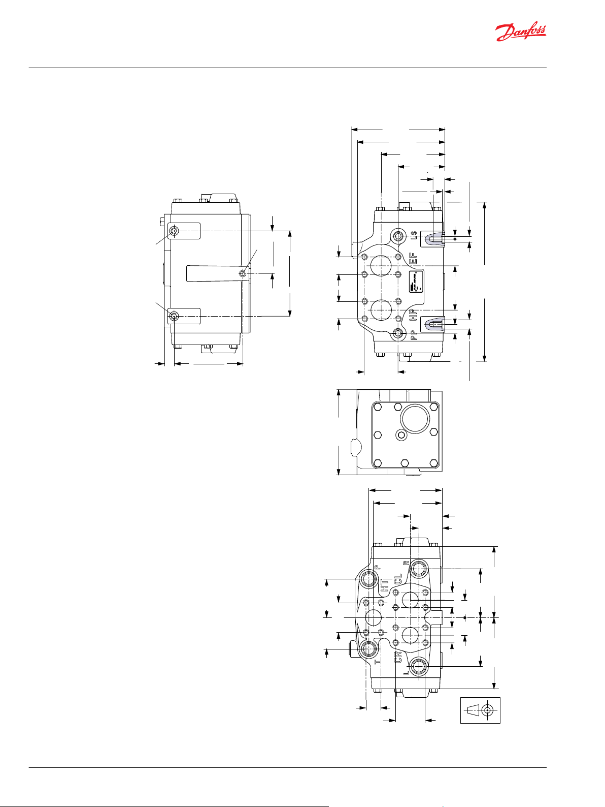
150F37.10
129 [5.08]
17 [0.67]
120.2 [4.73]
119.8 [4.72]
165 [6.50]
153 [6.02]
112 [4.41]
82 [3.23]
58.7 [2.31]
min. 21 [0.83]
5.3 [0.21]
4.7 [0.19]
121 [4.76]
56 [2.20]
41 [1.61]
31 [1.22] 31 [1.22]
26.2 [1.03]26.2 [1.03]
26.2 [1.03]
52.4 [2.06]
86 [3.39] 86 [3.39]
68 [2.68]
150 [5.91]
16 [0.63]
78 [3.07]
30.2 [1.19]30.2 [1.19]
47 [1.85] 5 [0.20]
75.2 [2.96]
74.8 [2.94]
150.2 [5.91]
149.8 [5.90]
285 [11.22]
Ø16.018 [0.631]
Ø16.000 [0.630]
Ø16.018 [0.631]
Ø16.000 [0.630]
55 [2.17]
52.4 [2.06]
125 [4.92]
125 [4.92]
A
A
B
Technical Information
OSPB/C/F/D/L LS Steering Units, OLS Priority Valves, OSQ Flow Amplifiers
Flow Amplifiers OSQA and OSQB
OSQB
European version: US version:
88 | © Danfoss | April 2021 BC152886483962en-001003
Page 89

Technical Information
OSPB/C/F/D/L LS Steering Units, OLS Priority Valves, OSQ Flow Amplifiers
Flow Amplifiers OSQA and OSQB
HP, EF:
1 1/4 in SAE flange
7/16-14 UNC
18 mm [0.71 in] deep (8)
HT, CL, CR:
1 in SAE flange
3/8 - 16 UNC
18 mm [0.71 in] deep (12)
P, T, L, R: G 1/2
PP, LS: G 1/4
A: M10 x 1,5, 21 mm [0.83 in] deep
B: M10 x 1,5, 16 mm [0.63 in] deep
HP, EF:
1 1/4 in SAE flange
7/16 - 14 UNC
18 mm [0.71 in] deep (8)
HT, CL, CR:
1 in SAE flange
3/8 - 16 UNC
18 mm [0.71 in] deep (12)
P, T, L, R: 3/4 - 16 UNF
PP, LS: 7/16 - 20 UNF
A: 7/16 - 14 UNC, 21 mm [0.83 in] deep
B: 7/16 - 14 UNC, 16 mm [0.63 in] deep
©
Danfoss | April 2021 BC152886483962en-001003 | 89
Page 90

Danfoss
Power Solutions GmbH & Co. OHG
Krokamp 35
D-24539 Neumünster, Germany
Phone: +49 4321 871 0
Danfoss
Power Solutions ApS
Nordborgvej 81
DK-6430 Nordborg, Denmark
Phone: +45 7488 2222
Danfoss
Power Solutions (US) Company
2800 East 13th Street
Ames, IA 50010, USA
Phone: +1 515 239 6000
Danfoss
Power Solutions Trading
(Shanghai) Co., Ltd.
Building #22, No. 1000 Jin Hai Rd
Jin Qiao, Pudong New District
Shanghai, China 201206
Phone: +86 21 2080 6201
Products we offer:
Hydro-Gear
www.hydro-gear.com
Daikin-Sauer-Danfoss
www.daikin-sauer-danfoss.com
Cartridge valves
•
DCV directional control
•
valves
Electric converters
•
Electric machines
•
Electric motors
•
Gear motors
•
Gear pumps
•
Hydraulic integrated
•
circuits (HICs)
Hydrostatic motors
•
Hydrostatic pumps
•
Orbital motors
•
PLUS+1® controllers
•
PLUS+1® displays
•
PLUS+1® joysticks and
•
pedals
PLUS+1® operator
•
interfaces
PLUS+1® sensors
•
PLUS+1® software
•
PLUS+1® software services,
•
support and training
Position controls and
•
sensors
PVG proportional valves
•
Steering components and
•
systems
Telematics
•
Danfoss Power Solutions is a global manufacturer and supplier of high-quality hydraulic and
electric components. We specialize in providing state-of-the-art technology and solutions
that excel in the harsh operating conditions of the mobile off-highway market as well as the
marine sector. Building on our extensive applications expertise, we work closely with you to
ensure exceptional performance for a broad range of applications. We help you and other
customers around the world speed up system development, reduce costs and bring vehicles
and vessels to market faster.
Danfoss Power Solutions – your strongest partner in mobile hydraulics and mobile
electrification.
Go to www.danfoss.com for further product information.
We offer you expert worldwide support for ensuring the best possible solutions for
outstanding performance. And with an extensive network of Global Service Partners, we also
provide you with comprehensive global service for all of our components.
Local address:
Danfoss can accept no responsibility for possible errors in catalogues, brochures and other printed material. Danfoss reserves the right to alter its products without notice. This also applies to products
already on order provided that such alterations can be made without subsequent changes being necessary in specifications already agreed.
All trademarks in this material are property of the respective companies. Danfoss and the Danfoss logotype are trademarks of Danfoss A/S. All rights reserved.
©
Danfoss | April 2021 BC152886483962en-001003
 Loading...