

Page 1

Application Guide
Optyma™ Trio
http://RA.danfoss.com.br
Page 2

Page 3

Application Guide
Content
1. Introduction ...................................................................................................................... 4
2. General Information ........................................................................................................ 5
2.1 Application envelope of the Condensing Units for R404A / R507 .............................................................5
2.2 Applications ...................................................................................................................................................................5
2.3 Features ........................................................................................................................................................................... 5
2.4 Benefits ............................................................................................................................................................................ 5
3. Specifications ................................................................................................................... 6
3.1 Illustrative Image .......................................................................................................................................................... 6
3.2 Nomenclature ............................................................................................................................................................. 7
3.3 Performance data ........................................................................................................................................................ 8
3.2 General Data .................................................................................................................................................................. 8
3.5 Electrical Data ............................................................................................................................................................... 8
3.6 Dimensional Data ....................................................................................................................................................... 9
4. Installation and Operation ............................................................................................ 10
4.1 Storage and Handling ...............................................................................................................................................10
4.2 Precautions ..................................................................................................................................................................10
4.3 Mechanical Installation ............................................................................................................................................ 11
4.4 Leak detection ............................................................................................................................................................ 12
4.5 Vacuum dehydration ................................................................................................................................................ 12
4.6 Electrical Installation.................................................................................................................................................12
4.7 Refrigerant and oil charge ......................................................................................................................................13
4.8 Verification before operating ................................................................................................................................13
4.9 First start-up ................................................................................................................................................................. 13
4.10 Verification of the unit while operating .......................................................................................................... 13
5. Maintenance ................................................................................................................... 14
6. Spare parts ...................................................................................................................... 15
7. Warranty .......................................................................................................................... 16
8. Danfoss Guideline .......................................................................................................... 17
3© Danfoss | Climate Solutions | 2022.03 AB260116321450en-000301
Page 4

Application Guide
1. Introduction
The content of this material applies only to
“Optyma
TM
TRIO” condensing units. This product
is a Danfoss technology solution with the use of
three in parallel connected scroll compressors
in a robust foil framework with high efficiency
micro-channel (MCHE) Danfoss condenser.
Even though a lot of benefits for the use of
in parallel compressor systems exist, the
more important benefits are the use of less
equipment, flexibility on the capacity control,
use of few tubing lines, better control of energy
consumption and reduction of installation
time when compared to the use of different
equipment with single compressor systems
to obtain the same capacity.
4 © Danfoss | Climate Solutions | 2022.03AB260116321450en-000301
Page 5

Application Guide
2. General Information
2.1 Application envelope of the Condensing Units for R404A / R507
Figure 1
50
45
40
35
30
25
20
T amb (°C)
15
10
5
0
-35 -30 -25 -20 -15 -10 -5 0510 15
2.2 Applications
T evap (°C)
This unit is intended for diverse applications,
such as:
• Medium capability refrigeration systems,
in general;
• Medium and small sized supermarkets;
MBP
2.3 Features
• Scroll Compressors;
• High efficiency micro-channel condenser;
• Designed to operate in locations with high
ambient temperature;
• Motorized fans of high performance and low
energy consumption to obtain the maximum
thermal efficiency;
• Motorized fans developed specially to
guarantee the perfect operation in humid
environments and great diversity of dirt;
• 6 pole motorized fans selected to assist in low
noise level operations with dynamic balancing;
• Designed for use in outdoor environments;
• Designed for easy installation and maintenance;
• Framework assembled in galvanized steel with
electrostatic painting resistant to corrosion;
• Distribution centers for freezing and food
preservation;
• Industrial systems;
• Cold water and liquid cooling units, etc.
• Removable fan guards to facilitate the cleaning
of the serpentine and general maintenance;
• Service valves in the liquid line and suction;
• Liquid receiver with service valves in the inlet
and outlet connections, according to the
NR10 norm;
• Combined oil separator and oil reservoir;
• Individual oil control for each compressor
through the electronic level regulators;
• Compressor with thermal shield for motor
protection against high temperatures and
currents;
• Applications for R404A;
• Electric panel according to the NR13 norm;
• There is enough space for the installation of
additional controls, if necessary.
2.4 Benefits
• Compact, light and resistant unit;
• Easy handling;
• Low noise level, 6-pole fan;
• High performance;
• Low energy consumption.
5© Danfoss | Climate Solutions | 2022.03 AB260116321450en-000301
Page 6

Application Guide
3.1 Illustrative Image
Figure 2
3. Specifications
6 © Danfoss | Climate Solutions | 2022.03AB260116321450en-000301
Components
1 - Fan
2 - Micro-channel type condenser
3 - Electronic oil level control valve
4 - Scroll Compressors
5 - Combined separator and oil reservoir
6 - Oil filter
7 - Liquid receiver
8 - Base
9 - Service valve ( GBC) liquid line
10 - Service valve (GBC) suction line
11 - Sight glass
12 - Suction filters and liquid line
13 - High and low security pressure switch
14 - Fan’s control pressure switch
15 - Suction accumulator
16 - Complete electric panel (including
sectionalizers, compressor contactor,
overload relay, fan contactor, circuit breaker,
timers, fault relay/ phase sequence).
Page 7
Application Guide
3. Specifications
3.2 Nomenclature
3.2.1 Code and model
Nomenclature for the Optyma™ Trio line
H U D Q5100 50
1 2 3 4 5 6
1
H - High and medium evaporating temperature
Application
2
U - R404A / R507
Coolant gas
3
Compressors’
51(00) - 51000 Kcal/h for HBP/MBP
capacity (Kcal/h)
4
Condenser’s
D - Micro-channel
technology
5
Table 1
Productconfiguration
6
Electrical Codes
Q - 220V/3F/60Hz
V - 380V/3F/60Hz
Table 1 - Productconfiguration
Pressure
switch
Code
Application
50 HBP 3 2 1 1 1 1 1 1 1 1 1 3 4 3 4 3
KP5 Fa n
KP15 S afety
Separator
Liquid receiver
andoilreservoir
Filter Drier
Suction
accumulator
Suction
L. Liquid
Service Valve Electric Component
Contactor Circuit breaker
Liquid
Sight Glass
Suction
line
General
Key
Compressor Fan Compressor Fan
Sequence
protector
phase
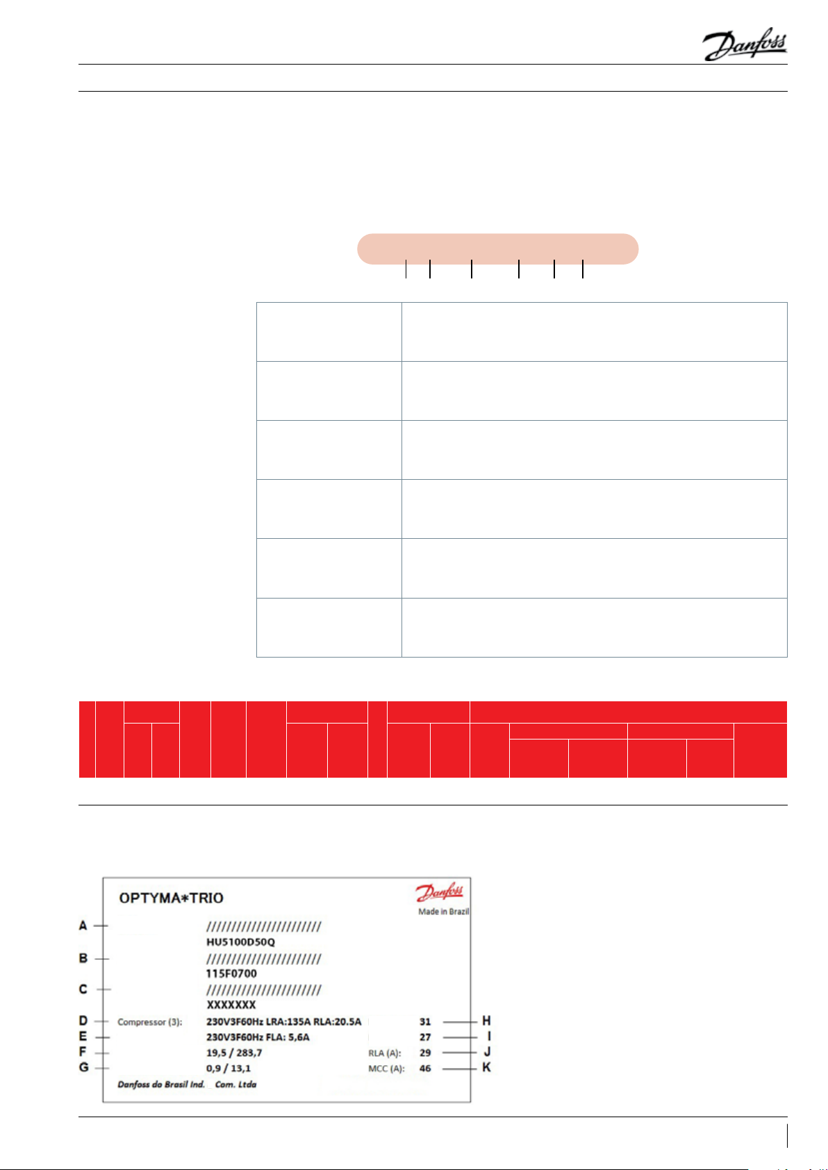
3.2.2 Label
Figure 3
Model:
Code:
Serial:
Fan (4):
HP Pressure (bar/psi):
LP Pressure (bar/psi):
A: Model
B: Code
C: Serial number and Bar code
D: Compressors Information
E: Fans Information
F: HP pressure test
Apparent P.
Active P. (kw)
G: LP pressure test
H: Apparent power
I: Active power
J: RLA nominal current
e
K: Maximum current of MCC application
7© Danfoss | Climate Solutions | 2022.03 AB260116321450en-000301
Page 8

Application Guide
3.3 Performance data
3. Specifications
HBP R404A/R507 60Hz
Condensing Unit
Model Electrical Code Code C.R. P.C. C.R. P.C. C.R. P.C. C.R. P.C. C.R. P.C. C.R. P.C. C.R. P.C.
HU4500D50
HU510 0D50
KEY
C. R. capacity ( Kcal/h )
P.C. Total power including fans (KW)
Q
V
Q
V
115F05 59
115F05 60
115F05 61
115F05 62
Ambient
32 22170 22.35 27880 22.68 34510 23.22 42030 23.93 50390 24.74 5954 0 25.64 69420 26.58
35 ---- ---- 26120 23.95 32430 24.43 39590 25.09 47560 25.89 56290 26.78 65730 27. 73
38 ---- ---- 24070 25.34 30290 25. 76 37090 26.36 44650 27. 12 52950 27. 99 61950 28.94
43 ---- ---- 20900 28.00 26610 28.26 32760 2 8.74 39630 2 9.41 47210 30.23 ---- ----
32 26090 25.90 32180 26.58 3920 0 27. 45 4 7170 28.47 56080 29.60 65900 30.79 7660 0 31.99
35 ---- ---- 30490 2 7.98 37210 28.83 44830 29.84 53330 30.96 62720 32.14 72990 33.34
38 ---- ---- 28840 28.43 3518 0 30. 31 42430 31.3 0 50540 32.40 5950 0 33.57 69320 34.77
43 ---- ---- 25880 31.05 3178 0 31.81 38320 33.96 4576 0 35.02 54000 36.16 ---- ----
-25 -20 -15 -10 -5 0 5
Temperature (°C)
OPERATING CONDITIONS:
Overheating: 20 K
Sub-cooling: 0 K
Cooling capacity in (Kcal/h) - Evaporating temperature in (°C)
3.2 General Data
Condensing Unit Compressor Fan Condenser
(HP)
Chassis
Application
HBP
23
C
27
Model
HU4500D50Q 115F05 59 MLZ058T2 121L8 816
HU4500D50V 115 F056 0 MLZ058T9 121L88 24
HU510 0D50Q 115F05 61 MLZ066T2 121L88 26
HU510 0D50V 115 F0562 MLZ066T9 121L8 852
Code
Qty
Model
Code
3 26.4 2.7 630 6 4 33600 Q8 2.54 x 2 40 2 1/8 1 1/8 485 500 64 78 86
3 31.2 2.7 630 6 4 33600 Q8 2.54 x 2 40 2 1/8 1 1/8 485 500 64 78 86
Diam.
(m3/h)
Qty
(mm)
No. Poles
(m3/h)
Air flow
(L)
Oil
Off
(L)
Typ e
Internal Vol.
Connection Weight Sound level
(in)
(in)
Liq.
(Kg)
(Kg)
Liquid Receiver
L. Liq.
L. Suction
Raw
dB2mdB
5m
60Hz
Sound Power dBA
3.5 Electrical Data
60Hz
Condensing Unit Compressor Fan
Model
HU4500D50Q 115F05 59 33.53 230V-3F-60Hz 88.00 MLZ058T2 121L8 816 3 230V-3F-60Hz 190. 0 25.6 40.0 630 4 6 870 230V-3F-60Hz 2.9 1.65
HU4500D50V 115 F056 0 35.80 380V-3F-60Hz 54.40 MLZ058T9 121L 8824 3 380V-3F-60Hz 13 5.0 16.0 25.0 630 4 6 870 380V-3F-60Hz 2.9 1.65
HU510 0D50Q 115F05 61 37.99 230V-3F-60Hz 99.70 MLZ066T2 121L88 26 3 230V-3F-60Hz 235.0 29. 5 46.0 630 4 6 870 230V-3F-60Hz 2.9 1. 65
HU510 0D50V 115 F0562 43.70 380V-3F-60Hz 66.40 MLZ066T9 121L88 52 3 380V-3F-60Hz 135 .0 20.0 28.0 630 4 6 870 380V-3F-60Hz 2.9 1.65
LRA: Rotor amps blocked, RLA: Nominal current, MCC: Maximum direct current, FLA: Full charge current
Code
Tot al po wer
kVA MCC LRA RLA MCC mm W 230V (A) 380V (A)
Frequency
Voltage, Phases,
Amps
Model
Qty
Code
Frequency
Voltage, Phases,
Amps
Diam. Model
Power
Qty
No. Poles
Frequency
Voltage, Phases,
FLA (60Hz)
8 © Danfoss | Climate Solutions | 2022.03AB260116321450en-000301
Page 9

Application Guide
3. Specifications
3.6 Dimensional Data
Dimensions (mm) Connections
Condensing Unit
HU4500D50Q 14 85 2057 1368 15 85 2157 14 68 250 224 24 6 348
HU4500D50V 1485 2057 1368 158 5 2157 14 68 250 224 246 348
HU510 0D50Q 1485 2057 1368 15 85 2157 14 68 250 224 24 6 348
HU510 0D50V 1485 2057 136 8 158 5 2157 1468 250 224 246 348
Without packaging With packaging Liquid Line Liquid Line
W L H X Y Z A B C D
Figure 4
9© Danfoss | Climate Solutions | 2022.03 AB260116321450en-000301
Page 10

Application Guide
4. Installation and Operation
4.1 Storage and Handling
4.2 Precautions
To guarantee an adequate protection,
it is necessary to observe all emphasized
recommendations in this application guide.
• It is not recommended to open the packaging
before the unit being at the installation site.
• Handle the unit carefully. The framework
allows the use of a forklift or handling cart. Use
appropriate and safe elevation equipment.
• Keep the unit in a vertical position both in
storage and transport.
• Store the unit in an adequate and protected
environment.
• Do not expose the packaging to rain or
corrosive atmosphere.
• After unpacking, verify if the unit is complete
and undamaged.
• The installation and maintenance of this unit
must only be held by a certified installer /
engineer / electrician and in accordance with
the local regulatory guidelines.
• Never place the unit in a flammable atmosphere
• Place the unit in a way that it doesn’t block or
complicate the passage areas, doors, windows,
stairs and other accesses.
• Ensure adequate space around the unit for
the air circulation and door opening. See Figure
5 to obtain the minimum distance values to
the walls.
• Avoid installing the unit in aggressive
environments and with difficult access.
• Ensure a base with strong horizontal surface
that is stable enough to support all the
unit’s weight and eliminate the vibrations
by misalignment.
The next sections will provide necessary
recommendations for the installation and
operation of the Optyma
safety data and appropriate use of the product.
All the equipment must be examined carefully
upon product receipt in order to verify if
no damages were caused by handling and
transportation.
This equipment was carefully inspected in
our factory, in case there is any apparent or
hidden malfunction, notify immediately the
establishment where it was purchased.
• Check if the power supply corresponds
to the technical specifications of the unit
(see product’s marking label).
• By installing units for HFC refrigerants, use
specific equipment for that type of refrigerant,
in other words, that have never been used
before for CFC or HCFC.
• The suction tubing must be flexible in 3 dimensions
to muffle the vibrations. Furthermore, the tubing
must be done in a way so that the return of the
oil to the compressor is ensured and the return of
liquid refrigerant to the compressor is avoided.
The installation at ground level rarely presents
problems, none the less, if it is not installed at
ground level, an additional tubing for drainage
must be considered in the project.
TM
Trio unit, as well as
10 © Danfoss | Climate Solutions | 2022.03AB260116321450en-000301
Page 11
Application Guide
4. Installation and Operation
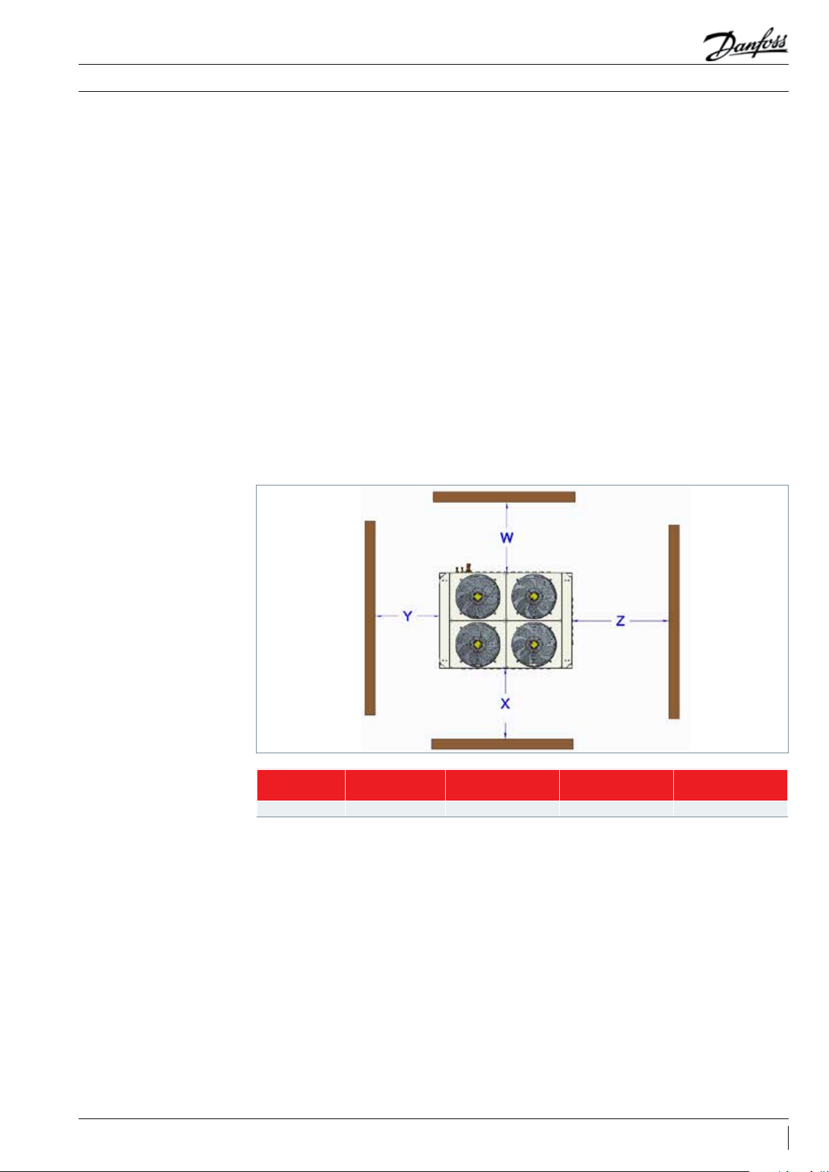
4.3 Mechanical Installation
Figure 5
• The installation of the unit must comply with
all the current safety local regulations, under all
circumstances.
• The unit must be installed securely on a bracket
or a steady and secure base, with the use of the
vibration shock absorbers with mounting bolts
provided together with the unit. See Figure 6.
• Remove the nitrogen load slowly through the
schrader valves located in the suction GBC
service valves and liquid line.
• Connect the unit to the system as quickly as
possible to avoid the oil contamination from
moisture present in the air.
• Avoid the penetration of solid residues derived
from the tubing burr and others.
• Weld the tubing with proper material and always
use nitrogen gas flow to make the environment
inert, avoiding internal carbonation and forming
of residue that may damage the system.
• It is recommended to isolate the suction tubing
with insulation thickness that meets the specific
project conditions for the installation.
• For the initial start-up, the oil level must be
verified and completed with a parcial load, with
the oil provided together with the condensing
unit. If more oil is required, acquire from an
oil distributor the oil of the same brand and
specification provided with the condensing unit.
• After the operation, the sight glass of the oil
compressor must be re-checked and the oil load
completed to adjust to the installation tubing
length, if necessary.
• It is recommended to put the oil through the
service valve of the oil separator/trap through
a vacuum pump connected to the high pressure
line.
• The refrigerant charge must be done through the
liquid’s tank service valve or through the schrader
of the GBC service valve of the liquid line.
W
[mm]
Chassis - C 1092 1092 1000 190 0
Note: The specification of the chassis for each model can be found in section “3.6 Dimensional Data” in page 11.
X
[mm]
Y
[mm]
Z
[mm]
11© Danfoss | Climate Solutions | 2022.03 AB260116321450en-000301
Page 12

Application Guide
4.3.1 Fixation
Figure 6
4. Installation and Operation
Fixation of 4 “vibra-stop” type shock
absorbers included on the Danfoss
supply for the support on the floor
or laying base
4.4 Leak detection
4.5 Vacuum dehydration
4.6 Electrical Installation
• Never pressurize the circuit with oxygen or
dry air. This can cause fire or explosion.
• Do not use dye for leak detection.
• The use of nitrogen or the system’s own gas
is recommended.
• Never use the compressor to empty the system.
• Connect a vacuum pump to the system’s lower
sides LP and HP.
• The vacuum in the system must reach at least a
complete 500 μm Hg (0.67 mbar).
• When the vacuum level is reached, keep it for a
few hours to guarantee the sealing of the system.
• After this stage, isolate the vacuum pump and
place the nitrogen with a pressure of 4 to 5 bar,
keeping the system at this pressure for 4 hours.
• Switch off and isolate the main power supply.
• Make sure that the power supply can’t be
switched on accidentally during installation.
• All the electrical components must be selected
according to the local standards and according
to the unit’s requirements.
• Consult the wiring diagram supplied with the
installation manual for details on electrical
connections.
• Make sure that the power supply matches the
unit characteristics and that the energy source
is stable (nominal voltage ± 10% and nominal
frequency ± 2.5 Hz).
• Dimension the power supply cables according
to the unit data on voltage and current.
• Protect the power supply and ensure that the
grounding of the unit is done according to the
current standards.
• Perform a leak detection test in the entire
system.
• The maximum test pressure is 32 bar.
• When a leak is detected, repair the leak
and repeat the leak detection.
• If the pressure in the gauge connected to the
suction line and discharge lowers in this period,
locate the leak, perform the repair and restart
the vacuum procedure and check the leak again.
• Do not apply energy to the unit while the
system is under vacuum, as this might cause
internal damage.
• The unit is equipped with high and low pressure
switches, which directly shut off the power
supply to the compressor in case of activation.
The unit is also equipped with a phase sequence
relay to protect the unit against phase/
sequence loss / asymmetry and under voltage /
over voltage.
• Observe the correct phase sequence in the
condensing units which use three-phase
compressors.
• Determine the sequence using a phase gauge
to establish the sequences of the line phases L1,
L2 e L3.
• Connect the line phases L1, L2 e L3
corresponding to the terminals of the
compressor T1, T2 e T3 respectively.
12 © Danfoss | Climate Solutions | 2022.03AB260116321450en-000301
Page 13

Application Guide
4. Installation and Operation
4.7 Refrigerant and oil charge
4.8 Verification before
operating
4.9 First start-up
• Use individual protection equipment (IPE)
such as safety glasses and gloves.
• Never start the compressor under vacuum.
Keep the compressor switched off.
• Before performing the refrigerant charge,
verify if the oil level is between ¼ and ¾ on the
compressor oil display. If necessary, add oil to
the compressors, refer to the compressor’s label
for oil type.
• Only use the coolant for which the unit was
designed for.
• Perform the refrigerant charge in liquid phase
into the condenser and in the liquid receiver.
• Use safety devices according to locally
applicable regulations and security standards.
• Verify if all electrical connections are attached
correctly and in accordance with the local
regulations.
• Never switch on the unit without having
performed a refrigerant charge .
• All service valves must be in the open position.
See figure 5.
• Verify if the power supply is adequately
connected.
• Verify if the crankcase heater is working.
• Verify if the fan can rotate freely.
• Verify if high and low pressure are balanced.
• Energize the unit and verify the conformity of
the wiring, the tension in the terminals and the
phase sequence.
Make sure to perform a slow refrigerant
charge until it reaches 4-5 bar in systems
with R404A/507.
• Never put liquid refrigerant through the
suction line.
• Never use additive or oil mixtures.
• The remaining charge is carried out until the
installation has reached a stable nominal
condition level during the operation.
• Never leave the filling cylinder connected to
the system.
• Keep the crankcase heater switched on for at
least 12 hours before the system start-up, for the
guarantee of proper lubrication and elimination
of the liquid refrigerant from the compressor's
crankcase.
• The potential reverse rotation of a three-phased
compressor can be detected by no pressure
increase, an abnormal sound level of the
compressor and a lower energy consumption
than the one expected. In this case, immediately
switch off the unit and connect the phases to
their appropriate terminals.
• If the direction of rotation is correct, the indication
of low pressure on the low pressure gauge must
display a decreasing pressure and the indication
of high pressure in the high pressure measurer
must display an increasing pressure.
• The electronic buoys must comply with the
indication.
4.10 Verification of the unit
while operating
• Check the rotation direction of the fan. The air
must flow from the condenser to the fan (air
flow from bottom to top).
• Check the high pressure stabilization and the
power supply stability.
• Check the suction overheating to reduce the risk
of the return of liquid to the compressor.
• Observe the compressor oil level in the
beginning and during the operation to confirm
that the oil level remains visible.
• Verify all tubing with respect to unusual
vibration. The movements exceeding 1.5mm
require corrective measures, as the use of
fixation supports in the tubing.
• Before leaving the installation site, perform
a general inspection of the installation on
cleanliness, detection of noise and leakage.
• Record type and amount of refrigerant charge,
as well as operation conditions as reference for
future inspections. Use data check sheet
13© Danfoss | Climate Solutions | 2022.03 AB260116321450en-000301
Page 14

Application Guide
5. Maintenance
• Always switch off the unit with the main switch
before removing the fan panel, or any other
panel of the condensing unit.
• The internal pressure and the surface
temperature are hazardous and can cause
permanent injuries.
• The installers and/or maintenance operators
must be certified in accordance with the current
standards and with the use of appropriate tools.
• High pressure tubing temperature may exceed
100°C and cause severe burns.
• Make sure that periodical inspection services
are carried out to guarantee the reliability of
the system and to meet the mandatory local
regulations.
• To ensure the good functioning of the unit and
its energy efficiency, it is recommended:
• Periodic maintenance;
• Verify if the safety devices are operational
and properly set;
• Make sure the unit retains the fixation
steady without fragility;
• Check if the compressor’s current is correct;
• Confirm if the system is operating
consistently with previous maintenance
records in the established conditions;
• Check if all electrical connections still are
properly attached;
• Keep the unit clean and without rust and
oxidation of the unit’s components, tubing
and electrical connections.
• The condenser must be verified at least once
a year regarding the blockage of the fins by
impurities and must be cleaned if considered
necessary. The access to the internal side of
the condenser takes place through the fans
panel (guard). The micro-channel coils tend
to accumulate dirt on the surface and not in
the interior, which makes them easier to clean
comparing to the tube condensers and fins.
• Remove the dirt from the surface, leaves, fibers,
etc., with a vacuum, equipped with a brush
or other soft accessory. Alternatively, blow
the compressed air through the condenser
inside out and brush with a soft bristle. Do not
use a wire brush. Do not impact or scrape the
condenser with the vacuum tube or air orifice.
• If the refrigeration system is open, the system
must be pressurized with nitrogen processed in
vacuum to remove the moisture and a new filter
drier must be installed.
14 © Danfoss | Climate Solutions | 2022.03AB260116321450en-000301
Page 15

Application Guide
Condensing Units HU4500D50Q HU4500D50V HU5100 D50Q HU5100 D50V
Accumulator 191U0 068 191U00 68 191U 006 8 191U006 8
Acoustic Hood - - - -
Compressor 121L88 16 121L88 24 121L 8826 121L 885 2
MCHE Condenser 193U 064 6E 193U 064 6E 193U 064 6E 193U0 646 E
Crankcase Resistance - - - -
Motor Fan 191U135980 191U135980 191U135980 191U135980
Filter Drier 023U1392 023U1392 023U1392 023U1392
Oil Filter 191U008810 191U008810 191U008810 191U008810
Oil Level Regulator 191U0 0903 0 191U0 09030 191U0 090 30 191U00 9030
Lubricating Oil 120Z5 034 12 0Z5 034 12 0Z503 4 12 0Z50 34
Oil Separator 191U0 0795 0 191U00795 0 191U 007950 191U 0079 50
KP HP_LP Pressure Switch 06 0-1264 66 0 60-126 466 06 0-12 646 6 06 0-126 466
KP HP Pressure Switch 060 -117166 0 60 -1171 66 0 60 -11716 6 060 -11716 6
6. Spare parts
15© Danfoss | Climate Solutions | 2022.03 AB260116321450en-000301
Page 16

Application Guide
7. Warranty
• Always have the model and serial number of the
condensing unit available for any warranty claim.
• The warranty of the product can be rendered
void in the following cases:
- Absence of nameplate.
- External modifications, mainly drilling, welding,
broken feet and shock markings.
- Open compressor or returned without sealing.
- Dye for rust detection, water or leak in the
compressor.
- Use of an off-specification refrigerant or
lubricant.
- Any deviation from the recommended
instructions regarding the installation,
application or maintenance.
- Use of the unit in an environment with an
explosive atmosphere.
- No model number or serial number was
informed in the warranty claim.
16 © Danfoss | Climate Solutions | 2022.03AB260116321450en-000301
Page 17

Application Guide
8. Danfoss Guideline
Danfoss recommends that gases, oils and
other components that can adversely affect
the environment be delivered to dedicated
companies in the recycling or disposal of those
materials for environment protection.
17© Danfoss | Climate Solutions | 2022.03 AB260116321450en-000301
Page 18
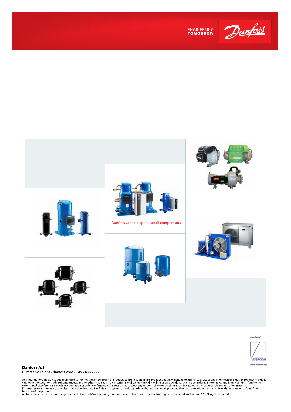
Danfoss Commercial Compressors
Danfoss variable speed scroll compressors
is a worldwide compressor and condensing units manufacturer for refrigeration and HVAC applications. With a wide range of innovative
products of the best quality, we help your company to find the best possible solution in terms of
environment and that reduces the total costs of the product’s life cycle.
We have over 40 years of experience in the development of hermetic compressors which placed us among the global leaders in our business
and positioned us as variable speed technology specialists. Currently we act from the engineering and project up to the production stages in
three continents.
energy efficiency and respect for the
Danfoss Turbocor Compressors
Danfoss scroll compressors
for air conditioning
Danfoss OPTYMA condensing units
Maneurop reciprocating compressors
Compressors for light applications
of commercial refrigeration
Our products can be found in diverse applications, such as rooftops, chillers, residential air conditioning,
heat pumps, cold rooms, supermarkets, milk cooling tanks and industrial cooling processes.
AB260116321450en-000301
© Danfoss | Climate Solutions | 2022.03
 Loading...