

Danfoss OPTYMA SLIM PACK OP-LSHM Series, OPTYMA SLIM PACK OP-MSUM Series, OPTYMA SLIM PACK OP-MSHM Series Instructions Manual
Page 1
INSTRUCTIONS
OPTYMA™ SLIM PACK OP-LSHM/MSUM/MSHM
English / English p. 4
Français / French p. 10
Polski / Polish p. 16
Español / Spanish p. 22
Deutsch / German p. 28
Dansk / Danish p. 34
Svenska / Swedish p. 40
Português / Portuguese p. 46
Nederlands / Dutch p. 52
Suomi / Finnish p. 58
Elinika / Greek p. 64
Norsk /Norwegian p. 70
български (Bălgarski) / Bulgarian p. 76
Română / Romanian p. 82
Čeština / Czech p. 88
Русский/Russian p. 94
Italiano / Italian p. 100
FRCC.EI.026.A5.ML Danfoss Commercial Compressors - 09/14
Page 2
Instructions
OP-LSHM015 - 018, OP-MSHM010 - 012 - 015 - 018
OP-LSHM026 - 034 - 048 - 068 - 074, OP-MSHM024 - 026 - 034, OP-MSUM034 - 046 - 057
FRCC.EI.026.A5.ML © Danfoss Commercial Compressors 09/142
Page 3
Instructions
OP-LSHM067 - 084 - 098, OP-MSUM068 - 080 - 093 - 099 - 108
3FRCC.EI.026.A5.ML © Danfoss Commercial Compressors 09/14
Page 4

118UXXXX
INSTRUCTIONS
OPTYMA™ SLIM PACK OP-LSHM/MSUM/MSHM
L
MADE IN INDIA
A
OP-MSUM034MLW05E
Code no.:
B
Application
C
Refrigerant
D
M.W.P. HP
E
LP (1) 7 bar
Voltage 380-400V3N~/50Hz
F
LRA 30,5 7,5MCC
Serial No.
G
Barcode Serial No:
114X7062
MBP
(1) R404A, R507A
(1) 28 bar
123456CG0514
IP54
(2) R134a
(2) 23 bar
(2) 5 bar
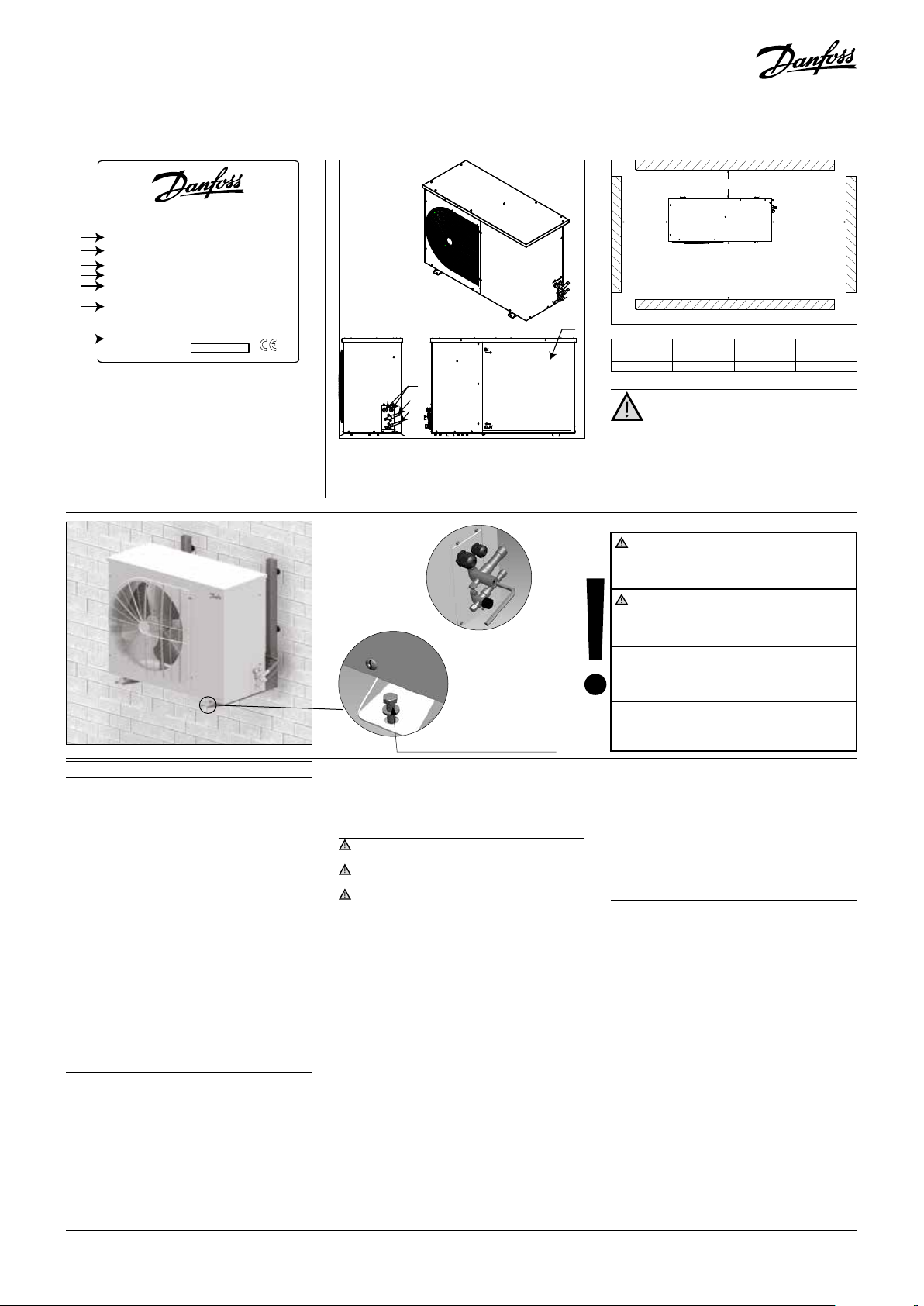
A: Model
B: Code number
C: Application, Protection
D: Refrigerant
E: Housing Service Pressure
F: Supply voltage, Locked Rotor Ampere,
Maximum Current Consumption
G: Serial Number and bar code
Picture 2
1 – Introduction
These instructions pertain to OptymaTM Slim
Pack condensing units OP-LSHM/MSUM/MSHM
(R507A, R404A, R134a, R22) used for refrigeration systems. They provide necessary information regarding safety and proper usage of this
product
The condensing unit includes following:
• Scroll/reciprocating compressor
• Microchannel heat exchanger
• Dual pressure switches
• Service valves Suction/ liquid
• Weather proof housing
• Filter drier
• Cranckcase heater for compressor
• Receiver with stop valve
• Sight glass
• Phase sequence relay (scroll compressors)
• Fully pre-wired electrical panel (including
main switch, compressors contactor, overload
relay)
2 – Handling and storage
• It is recommended not to open the packaging
before the unit is at the nal place for installation.
• Handle the unit with care. The packaging allows for the use of a forklift or pallet jack. Use
appropriate and safe lifting equipment.
• Store and transport the unit in an upright position.
• Store the unit between -35°C and 50°C.
• Don’t expose the packaging to rain or corrosive atmosphere.
4
FRCC.EI.026.A5.02 © Danfoss Commercial Compressors 09/14
K
H
I
J
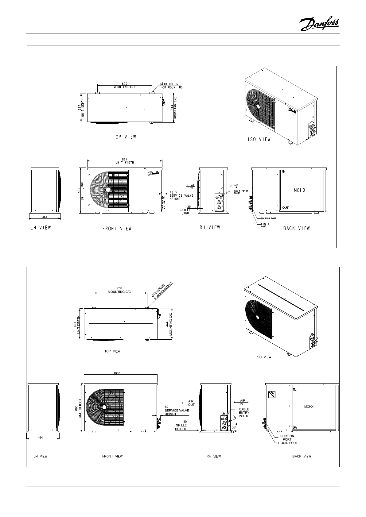
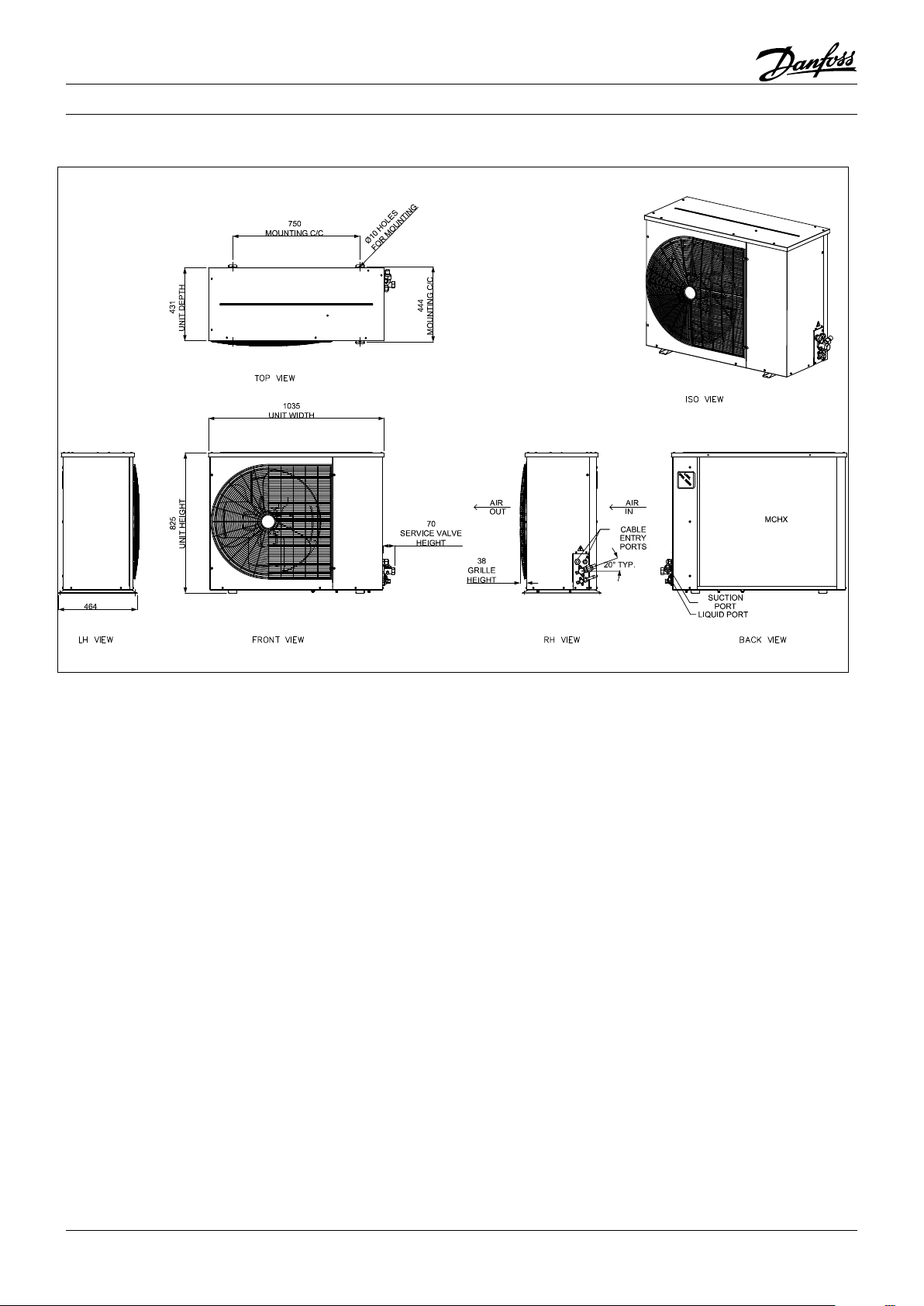
H: Cable entry ports
I: Suction port
J: Liquid port
K: Microchannel heat exchanger
Picture 3
Mounting bolts (not supplied)
• After unpacking, check that the unit is complete and undamaged.
3 – Installation precautions
Do not braze as long the condensing unit is
under pressure.
Never place the unit in a ammable atmosphere
Place the unit in such a way that it is not blocking
or hindering walking areas, doors, windows or similar.
• Ensure adequate space around the unit for air
circulation and to open doors. Refer to picture1 for minimal values of distance to walls.
• Avoid installing the unit in locations which are daily exposed to direct sunshine for longer periods.
• Avoid installing the unit in aggressive and
dusty environments.
• Ensure a foundation with horizontal surface
(less than 3° slope), strong and stable enough
to carry the entire unit weight and to eliminate vibrations and interference.
• The unit ambient temperature may not exceed 50°C during o-cycle.
• Ensure that the power supply corresponds to
the unit characteristics (see nameplate).
• When installing units for HFC refrigerants,
use equipment specically reserved for HFC
refrigerants which was never used for CFC or
HCFC refrigerants.
• Use clean and dehydrated refrigeration-grade
copper tubes and silver alloy brazing material.
• Use clean and dehydrated system components.
• The suction piping connected to the com-
N
M
Picture 1 : Minimum mounting distances
L
[mm]
250 650 550 550
M
[mm]
[mm]
O
N
O
[mm]
Installation and servicing of the
condensing units by qualied
personnel only. Follow these instructions
and sound refrigeration engineering practice
relating to installation, commissioning,
maintenance and service.
The condensing unit must only be used for
its designed purpose(s) and within its scope of
application.
Under all circumstances, the EN378 (or
other applicable local safety regulation)
requirements must be fullled.
The condensing unit is delivered under nitrogen gas pressure (1 bar) and hence it cannot
be connected as it is; refer to the «installation»
section for further details.
The condensing unit must be handled with caution in the vertical position (maximum oset
from the vertical : 15°)
pressor must be exible in 3 dimensions to
dampen vibrations. Furthermore piping has
to be done in such a way that oil return for the
compressor is ensured and the risk of liquid
slug over in compressor is eliminated.
4 – Installation
• The installation in which the condensing unit
is installed must comply to EEC Pressure directive (PED) no. 97/23/EC. The condensing unit
itself is not a ”unit” in the scope this directive.
• The unit must be securely installed on a stable
and rigid support, and xed from the beginning. See picture 2.
• It is recommended to install the unit on rub-
ber grommets or vibration dampers (not
supplied).
• Slowly release the nitrogen holding charge
through the schrader port.
• Connect the unit to the system as soon as possible to avoid oil contamination from ambient
moisture.
• Avoid material entering into the system while
cutting tubes. Never drill holes where burrs
cannot be removed.
• Braze with great care using state-of-the-art technique and vent piping with nitrogen gas ow.
• Connect the required safety and control devices. When the schrader port is used for this,
remove the internal valve.
• It is recommended to insulate the suction
pipe up to the compressor inlet with 19 mm
thick insulation.
Page 5
Instructions
5 – Leak detection
Never pressurize the circuit with oxygen or
dry air. This could cause re or explosion.
• Do not use dye for leak detection.
• Perform a leak detection test on the complete
system.
• The maximum test pressure is 32 bar.
• When a leak is discovered, repair the leak and
repeat the leak detection.
6 – Vacuum dehydration
• Never use the compressor to evacuate the system.
• Connect a vacuum pump to both the LP & HP
sides.
• Pull down the system under a vacuum of 500
μm Hg (0.67 mbar) absolute.
• Do not use a megohmmeter nor apply power
to the compressor while it is under vacuum as
this may cause internal damage.
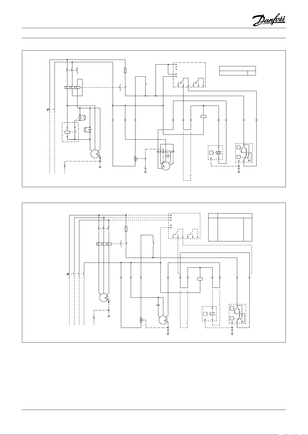
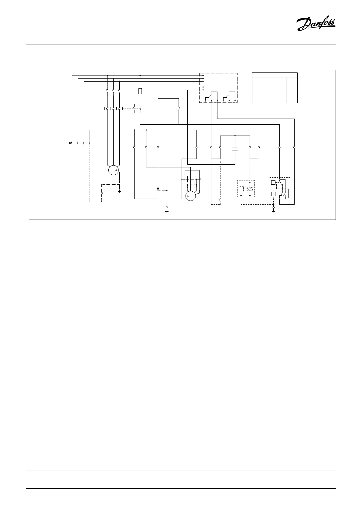
7 – Electrical connections
• Switch o and isolate the main power supply.
• Ensure that power supply can not be switched
on during installation.
• All electrical components must be selected as
per local standards and unit requirements.
• Refer to wiring diagram for electrical connections details.
• Ensure that the power supply corresponds to
the unit characteristics and that the power
supply is stable (nominal voltage ±10% and
nominal frequency ±2,5 Hz).
• Dimension the power supply cables according to unit data for voltage and current.
• Protect the power supply and ensure correct
earthing.
• Make the power supply according to local
standards and legal requirements.
•
The unit is equipped with high and low pressure switches, which directly cut the power
supply to the compressor in case of activation.
Parameters for high and low pressure cut outs
should be set by installer considering compressor model, refrigerant and application. Units
with Danfoss MLZ, LLZ and NTZ compressors
are also equipped with phase sequence relay to
protect the unit against phase loss/sequence/
asymmetry and under-/over-voltage.
For units with a 3-phase scroll compressor, correct phase sequence for compressor rotation
direction shall be observed.
• Determine the phase sequence by using a
phase meter in order to establish the phase
orders of line phases L1, L2 and L3.
• Connect line phases L1, L2 and L3 to main
switch terminals T1, T2 and T3 respectively.
8 – Filling the system
• Wear protective stu like goggles and protective gloves.
• Never start the compressor under vacuum.
Keep the compressor switched o.
• Before charging the refrigerant, verify that the
oil level is between ¼ and ¾ on the compressor
oil sight glass. If additional oil is required please
refer to the compressors label for type of oil.
• Use only the refrigerant for which the unit is
designed for.
• Fill the refrigerant in liquid phase into the
condenser or liquid receiver. Ensure a slow
charging of the system to 4 – 5 bar for R404A /
R507A or R22 and approx. 2 bar for R134a.
• Do not put liquid refrigerant through suction line.
• It is not allowed to mix additives with the oil
and/or refrigerant
• The remaining charge is done until the installation has reached a level of stable nominal
condition during operation.
• Never leave the lling cylinder connected to
the circuit.
9 – Verification before commissioning
Use safety devices such as safety pressure
switch and mechanical relief valve in compliance with both generally and locally applicable regulations and safety standards. Ensure
that they are operational and properly set.
Check that the settings of high-pressure switches and relief valves don’t exceed the maximum
service pressure of any system component.
• Verify that all electrical connections are properly
fastened and in compliance with local regulations.
• When a crankcase heater is required, it must
be energized at least 12 hours before initial
start-up and start-up after prolonged shutdown period.
10 – Start-up
• Never start the unit when no refrigerant is
charged.
• All service valves must be in the open position.
See picture 3.
• Check compliance between unit and power
supply.
• Check that the crankcase heater is working.
• Check that the fan can rotate freely.
• Check that the protection sheet has been re-
moved from the backside of condenser.
• Balance the HP/LP pressure.
• Energize the unit. It must start promptly. If
the compressor does not start, check wiring
conformity, voltage on terminals and sequence phase.
• Eventual reverse rotation of a 3-phase com-
pressor can be detected by following phenomena; unit doesn’t start, the compressor
doesn’t build up pressure, it has abnormally
high sound level and abnormally low power
consumption. In such case, shut down the
unit immediately and connect the phases to
their proper terminals.
• If the rotation direction is correct the low pres-
sure indication on the low pressure gauge
shall show a declining pressure and the high
pressure indication on the high pressure
gauge shall show an increasing pressure.
11 – Check with running unit
• Check the fan rotation direction. Air must ow
from the condenser towards the fan.
• Check current draw and voltage.
• Check suction superheat to reduce risk of
slugging.
• When a sight glass is provided observe the oil
level at start and during operation to conrm
that the oil level remains visible.
• Respect the operating limits.
• Check all tubes for abnormal vibration. Move-
ments in excess of 1.5 mm require corrective
measures such as tube brackets.
• When needed, additional refrigerant in liquid
phase may be added in the low-pressure side as
far away as possible from the compressor. The
compressor must be operating during this process.
• Do not overcharge the system.
• Never release refrigerant to atmosphere.
• Before leaving the installation site, carry out
a general installation inspection regarding
cleanliness, noise and leak detection.
• Record type and amount of refrigerant charge
as well as operating conditions as a reference
for future inspections.
12 – Maintenance
Always switch o the unit at main switch
before remove fan panel.
Internal pressure and surface temperature
are dangerous and may cause permanent injury.
Maintenance operators and installers require
appropriate skills and tools. Tubing temperature
may exceed 100°C and can cause severe burns.
Ensure that periodic service inspections to
ensure system reliability and as required by local
regulations are performed.
To prevent system related problems, following
Periodic maintenance is recommended:
• Verify that safety devices are operational and
properly set.
• Ensure that the system is leak tight.
• Check the compressor current draw.
• Conrm that the system is operating in a way
consistent with previous maintenance records and ambient conditions.
• Check that all electrical connections are still
adequately fastened.
• Keep the unit clean and verify the absence of
rust and oxidation on the unit components,
tubes and electrical connections.
The condenser must be checked at least once
a year for clogging and be cleaned if deemed
necessary. Access to the internal side of the
condenser takes place through the fan panel.
Microchannel coils tend to accumulate dirt on
the surface rather than inside, which makes
them easier to clean than n-&-tube coils.
• Switch o the unit at main switch before re-
move any panel from the condensing unit.
• Remove surface dirt, leaves, bres, etc. with
a vacuum cleaner, equipped with a brush or
other soft attachment. Alternatively, blow
compressed air through the coil from the inside out, and brush with a soft bristle. Do not
use a wire brush. Do not impact or scrape the
coil with the vacuum tube or air nozzle.
If the refrigerant system has been opened, the
system has to be ushed with dry air or nitrogen
to remove moisture and a new lter drier has to
be installed. If evacuation of refrigerant has to
be done, it shall be done in such a way that no
refrigerant can escape to the environment.
13 - Warranty
Always transmit the model number and serial number with any claim led regarding this product.
The product warranty may be void in following
cases:
• Absence of nameplate.
• External modications; in particular, drilling,
welding, broken feet and shock marks.
• Compressor opened or returned unsealed.
• Rust, water or leak detection dye inside the
compressor.
• Use of a refrigerant or lubricant not approved
by Danfoss.
• Any deviation from recommended instruc-
tions pertaining to installation, application or
maintenance.
• Use in mobile applications.
• Use in explosive atmospheric environment.
• No model number or serial number transmit-
ted with the warranty claim.
14 – Disposal
Danfoss recommends that condensing
units and oil should be recycled by a
suitable company at its site.
FRCC.EI.026.A5.02 © Danfoss Commercial Compressors 09/14
5
Page 6
Instructions
98
765
4
10
2 3
98
765
4
10
2 3
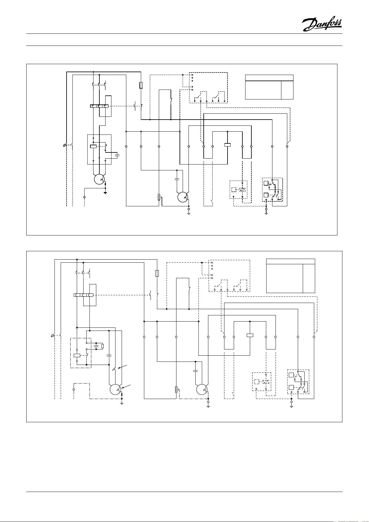
21
22
-K1
3A
1
2
-F3
95
96
97
98
BK
2 43
BUBNBN
BN
BN
PE
-X1
M
1~
-M2
-S1*
BK BN
1
2
1
-E1
BU
N2 5 6
BN
P
12PE
-B1*
BN
7
BU
BN
BN
8
P<
P>
B
C
A
D
PE
-B2
PE
-X1
BK
N1
-C3
A1
A2
-K1
MG73BF
SM500
16 18 15
L1
L2
L3
P
N
26 28 25
-A1*
M
1~
SCR
PE
-M1
12345
6
-K1
xxA
56341
2
-F2
-C2
-C1
-R1
BN
BU
5
2
1
44
5
-K2
BLBKBR
-F4
OP-.......AJW05G
OP-......SCW05G
BN
-F1
BU
230V1N~/50Hz
L PEN
PE
-X1
OP-......FHW05G
6,7AOP-MSHM018SCW05G
OP-LSHM026AJW05G
OP-LSHM034AJW05G
OP-LSHM048NTW05G
OP-LSHM068NTW05G
OP-LSHM074FHW05G
7,9A
10A
11A
17A
13A
15A
OP-MSHM026AJW05G
OP-MSHM034AJW05G
OP-MSHM024AJW05G 10A
-F2
24A
Code G : OP-MSHM010 - 012 - 015, OP-LSHM015 - 018
1
-F3
3A
2
95
97
98
96
.
.
N2
N1
BU
BK
-F1
12345
-K1
-F2
xxA
-K2
BU
BN
6
56341
2
BU
BN
10
11
14
12
-C2
13
13
-A1*
L1
SM500
L2
L3
MG73BF
P
16 18 15
.
2
BK
N
26 28 25
BN
BN
.
A1
-K1
4.3
A2
BN
21
-K1
22
.
1
BK BN
OP-MSHM010SCW05G
OP-MSHM012SCW05G
OP-MSHM015SCW05G
OP-LSHM015SCW05G
OP-LSHM018SCW05G
.
5.6
-F2
5,3A
6,3A
6,8A
5,5A
5,8A
BN
BN
.
.
7
8
BU
BN
.
-X1
L PEN
230V1N~/50Hz
-M1
PE
S C R
M
1~
PE
-E1
-C3
BUBNBN
1
2
-M2
1~
M
-X1
.
PE
Code G : OP-LSHM026 - 034 - 048 - 068 - 074, OP-MSHM018 - 024 - 026 - 034
-S1*
-B1*
-B2
A
P<
-X1
B
P>
D
C
PE
.
PE
P
12PE
Legend
BK black
BU blue
BN brown
GY grey
RD red
WH white
6
F4 Compressor thermal protector
M1 Compressor
M2 Fan motor
K1 Contactor
K2 Start relay
R1 Bleeder resistor
S1* Room thermostat (option)
X1 Terminals
* Option (remove bridge)
A1* Voltage relay (option)
B1* Fan speed controller (option)
B2 High and Low pressure switch
C1 Run capacitor compressor
C2 Start capacitor compressor
C3 Run capacitor fan
E1 Crankcase heater
F1, F3 Fuse (control circuit)
F2 Overload relay
FRCC.EI.026.A5.02 © Danfoss Commercial Compressors 09/14
Page 7

Instructions
98
765
4
10
2 3
98
765
4
10
2
3
2 4
3
BN
BN
BN
A1
A2
-K1
MG73BF
SM500
16 18 15
L1
L2
L3
P
N
26 28 25
-A1
-S1*
21
22
-K1
5 6
BN
P
12PE
-B1*
BN
7
BU
BN
BN
8
P<
P>
B
C
A
D
PE
-B2
PE
-X1
-F2
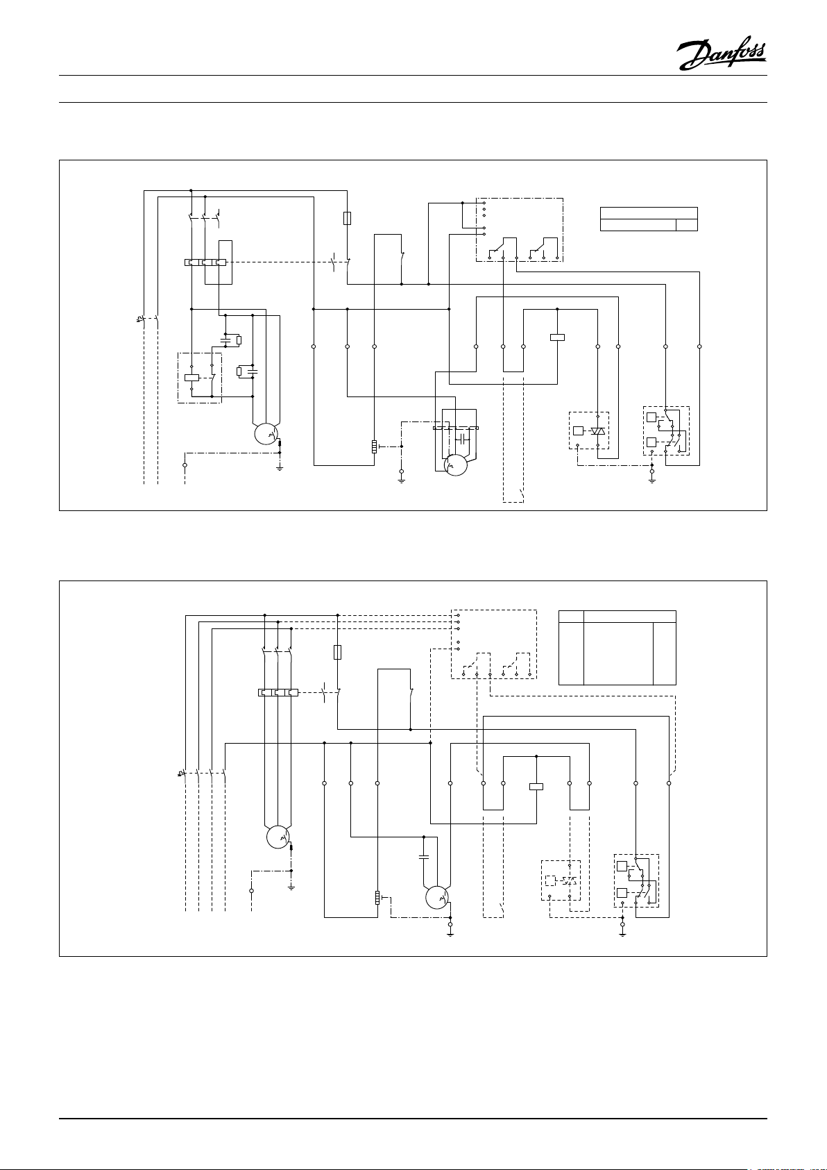
OP-MSUM068MLW05G
OP-MSUM080MLW05G
32A
38A
BKBUBN
WH
WH
1~
M
GNYE
-M2
BK BN
1
BK
N1
N2
3A
1
2
-F3
95
96
97
98
BK
BN
-C1
-R1
GY
M
1~
SCR
PE
-M1
12345
6
-K1
xxA
56341
2
-F2
BU
BN
BN
-F1
BU
PE
-X1
230V1N~/50Hz
L PEN
S
-X1
BU
PE
-X1
2
1
-E1
BN
-C3
Code G : OP-MSUM034 - 046 - 057
12345
-K1
-F2
xxA
2
BN
BU
BN
-F1
-X1
L PEN
230V1N~/50Hz
-C1
-R1
-M1
PE
6
56341
BU
BK
BN
S C R
M
1~
-A1
L1
SM500
2 4
BK
M
-X1
PE
L2
L3
P
N
16 18 15
BN
3
MG73BF
26 28 25
-K1
BN
-S1*
A1
A2
-B1*
5 6
BN
P
12PE
1
-F3
3A
2
95
97
98
96
N1
N2
BK
BU
GY
21
-K1
22
1
BK BN
-C3
PE
-E1
BUBNBN
1
-M2
2
1~
-F2
OP-MSUM034MLW05G
OP-MSUM046MLW05G
OP-MSUM057MLW05G
BN
BN
-B2
A
P<
B
P>
PE
-X1
PE
19A
25A
26A
BN
7
8
BU
D
C
Code G : OP-MSUM068 - 080
Legend
BK black
BU blue
BN brown
GY grey
RD red
WH white
A1* Voltage relay (option)
B1* Fan speed controller (option)
B2 High and Low pressure switch
C1 Run capacitor compressor
C2 Start capacitor compressor
C3 Run capacitor fan
E1 Crankcase heater
F1, F3 Fuse (control circuit)
F2 Overload relay
F4 Compressor thermal protector
M1 Compressor
M2 Fan motor
K1 Contactor
K2 Start relay
R1 Bleeder resistor
S1* Room thermostat (option)
FRCC.EI.026.A5.02 © Danfoss Commercial Compressors 09/14
X1 Terminals
* Option (remove bridge)
7
Page 8
Instructions
98
765
4
10
2 3
98
765
4
10
2 3
43
BN
BN
BN
A1
A2
-K1
BK
2
BKBUBN
WH
WH
1~
M
GNYE
-M2
21
22
-K1
95
96
97
98
3A
1
2
-F3
BK BN
1
BKN1BU
N2
MG73BF
SM500
16 18 15
L1
L2
L3
P
N
26 28 25
-A1
PE
-X1
2
1
-E1
-C3
12345
6
-K1
xxA
56341
2
-F2
BU
BN
BKBNBU
-C2
M
1~
SCR
PE
-M1
-R1
-C1
-R2
5
2
1
5
-K2
-S1*
BN
-F1
BU
230V1N~/50Hz
L PEN
PE
-X1
5 6
BN
P
21PE
-B1
BN
7
BU
BN
BN
8
PE
-X1
P<
P>
B
C
A
D
PE
-B2
-F2
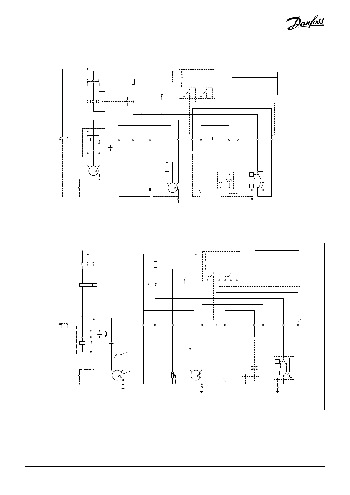
40AOP-MSUM093MLW06G
Code G : OP-MSUM093
Code E : OP-LSHM048 - 068 - 074, OP-MSHM026 - 034, OP-MSUM034 - 046 - 057
-A1*
L1
L2
BUBNBN
M
1~
-X1
16 18 15
2 43
BK
PE
L3
P
N
-F1
Legend
BK black
BU blue
BN brown
GY grey
RD red
WH white
8
BNBKGY
1234567
BU
8
-X1
L1 L2 PEL3 N
380-400V3N~/50Hz
-K1
-F2
xxA
12345
6
56341
2
-F3
1
3A
2
95
97
98
96
-K1
BN
1N2N1 5 6
BK
BU
1
-E1
2
-M1
BKGYBN
M
3~
PE
BK
A1* Voltage relay (option)
B1* Fan speed controller (option)
B2 High and Low pressure switch
C3 Run capacitor fan
E1 Crankcase heater
F1, F3 Fuse (control circuit)
F2 Overload relay
F4 Compressor thermal protector
FRCC.EI.026.A5.02 © Danfoss Commercial Compressors 09/14
21
22
-C3
-M2
SM500
MG73BF
26 28 25
-A1* -F2
--OP-MSHM026AJW05E
OP-MSHM034AJW05E
X
OP-MSUM034MLW05E
X
OP-MSUM046MLW05E
X
OP-MSUM057MLW05E
-
OP-LSHM048NTW05E
-
OP-LSHM068NTW05E
OP-LSHM074FHW05E 7,9A
-
BN
BN
M1 Compressor
M2 Fan motor
K1 Contactor
K2 Start relay
R1 Bleeder resistor
-K1
-S1*
A1
A2
-B1*
BN
-B2
P<
P
12PE
-X1
P>
PE
PE
S1* Room thermostat (option)
X1 Terminals
* Option (remove bridge)
4,0A
4,8A
7,0A
9,5A
10A
4,8A
8,4A
BN
BN
7
8
BU
BN
A
B
D
C
Page 9

Instructions
98
765
4
10
2
3
BN
-S1*
BN
P
12PE
-B1*
BU
BN
PE
-X1
P<
P>
B
C
A
D
PE
-B2
2 4
3
BN
BN
5
6
BN
7
BN
8
-F2
21
22
-K1
A1
A2
-K1
MG73BF
SM500
16 18 15
L1
L2
L3
P
N
26 28 25
-A1
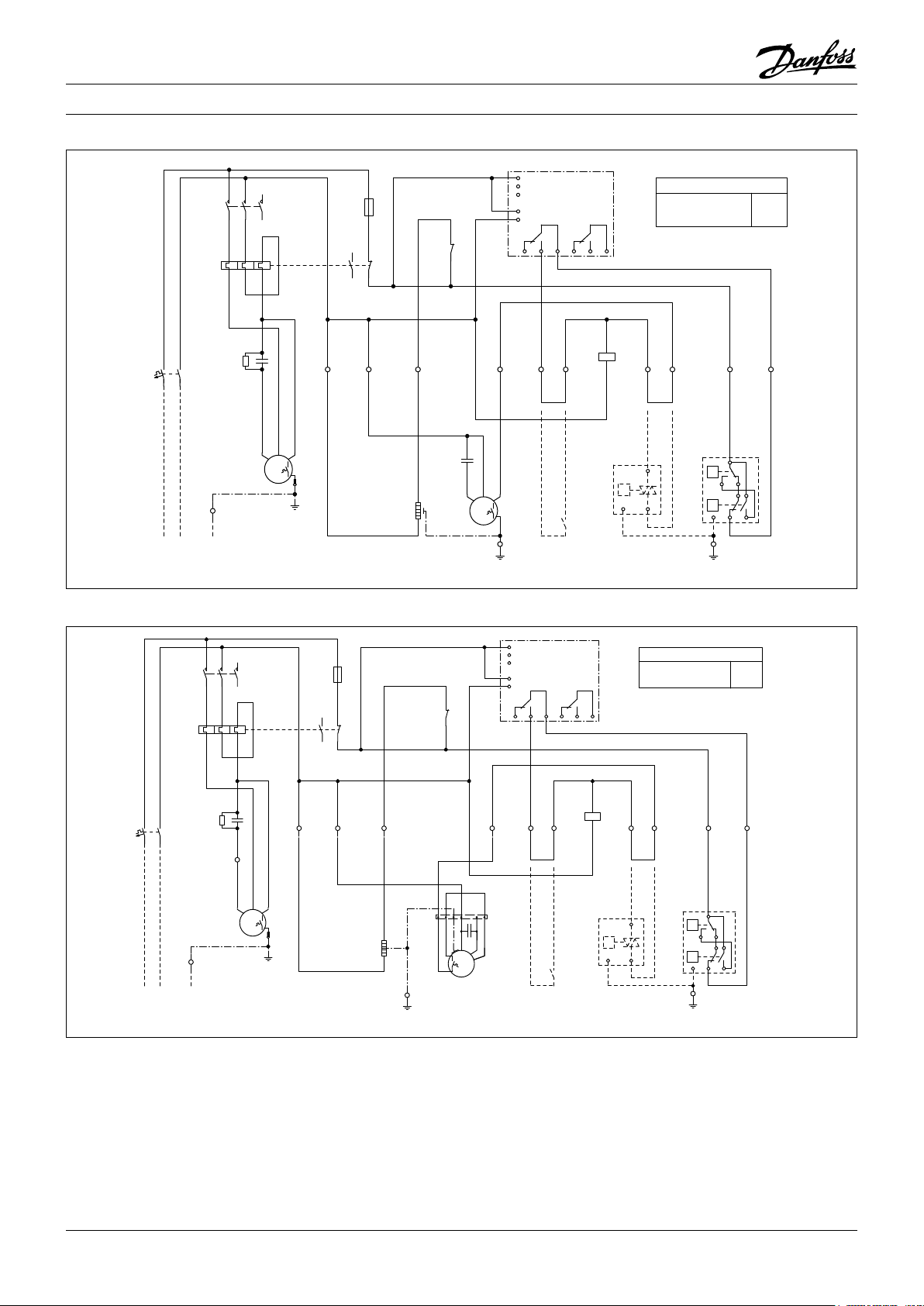
13A
15A
16A
15A
OP-MSUM068MLW05E
OP-MSUM080MLW05E
OP-MSUM099MLW05E
OP-MSUM108MLW05E
OP-LSHM067LLW05E
OP-LSHM084LLW05E
OP-LSHM098LLW05E
12A
15A
15A
BKBUBN
WH
WH
1~
M
GNYE
-M2
3A
1
2
-F3
95
96
97
98
12345
6
-K1
BKGYBN
M
3~
-M1
xxA
56341
2
-F2
BK
BU
BK
BN
1
N2
N1
BNBKGY
BU
PE
-X1
380-400V3N~/50Hz
L1 L2 PEL3 N
1234567
8
-F1
2
1
-E1
PE
-X1
BN
-C3
Code E : OP-MSUM068 - 080 - 099 - 108, OP-LSHM084 - 098
Legend
BK black
BU blue
BN brown
GY grey
RD red
WH white
A1* Voltage relay (option)
B1* Fan speed controller (option)
B2 High and Low pressure switch
C1 Run capacitor compressor
C2 Start capacitor compressor
C3 Run capacitor fan
E1 Crankcase heater
F1, F3 Fuse (control circuit)
F2 Overload relay
Danfoss can accept no responsibility for possible errors in catalogues, brochures and other printed material. Danfoss reserves the right to alter its products without notice. This
also applies to products already on order provided that such alterations can be made without subsequential changes being necessary in specications already agreed. All trademarks in this material are property of the respective companies. Danfoss and the Danfoss logotype are trademarks of Danfoss A/S. All rights reserved.
FRCC.EI.026.A5.02 - September 2014 Copyright Danfoss Commercial Compressors - DSS - 09/14
F4 Compressor thermal protector
M1 Compressor
M2 Fan motor
K1 Contactor
K2 Start relay
R1 Bleeder resistor
S1* Room thermostat (option)
X1 Terminals
* Option (remove bridge)
Page 10

118UXXXX
INSTRUCTIONS
OPTYMA™ SLIM PACK OP-LSHM/MSUM/MSHM
L
MADE IN INDIA
A
OP-MSUM034MLW05E
Code no.:
B
Application
C
Refrigerant
D
M.W.P. HP
E
LP (1) 7 bar
Voltage 380-400V3N~/50Hz
F
LRA 30,5 7,5MCC
Serial No.
G
Barcode Serial No:
114X7062
MBP
(1) R404A, R507A
(1) 28 bar
123456CG0514
IP54
(2) R134a
(2) 23 bar
(2) 5 bar
A: Modèle
: Référence - Code
B
C: Application, Protection
D: Réfrigérant
E
: Pression de service
F: Tension d’alimentation, Intensité en rotor
bloqué, Consommation de courant maximum
G: N° de série et code EAN
Illustration 2
1 – Introduction
Ces instructions concernent les groupes de condensation Optyma
(R507A, R404A, R134a, R22) utilisés pour les systèmes
de réfrigération. Elles fournissent les informations
nécessaires pour la sécurité et l’utilisation appropriée
de ce produit
Le groupe de condensation comprend les éléments
suivants:
• Compresseur piston/scroll
• Échangeur de chaleur à microcanaux
• Pressostats haute/basse pression
• Vannes de service, aspiration/liquide
• Capot résistant aux intempéries
• Filtre déshydrateur
• Résistance de carter pour le compresseur
• Réservoir avec vanne d’arrêt
• Voyant liquide
• Contacteur de phase (compresseurs scroll)
• Panneau électrique entièrement précâblé (y compris
sectionneur principal, contacteur de compresseur,
relais de surcharge)
2 – Manipulation et stockage
• Il est recommandé de ne pas ouvrir l'emballage
avant d'avoir positionné le groupe à son emplacement d'installation
• Manipulez le groupe avec soin. L'emballage permet
l'utilisation d'un chariot élévateur ou d'un transpalette. Utilisez un équipement de levage approprié et
sûr.
• Stockez et transportez le groupe en position verticale.
• Stockez le groupe à une température comprise entre
-35°C et 50°C.
TM
Slim Pack OP-LSHM/MSUM/MSHM
K
H
I
J
H: Orices d'entrée de câble
I: Orice d'aspiration
J: Orice de liquide
K: Échangeur de chaleur à microcanaux
Illustration 3
Boulons de montage (non fournis)
• N'exposez pas l'emballage à la pluie ou à une atmosphère corrosive.
• Après le déballage, vériez que le groupe est complet et qu'il n'est pas endommagé.
3 – Précautions d'installation
Ne pas braser tant que le groupe de condensation
est sous pression.
Ne placez jamais le groupe dans une atmosphère
inammable.
Placez le groupe de manière à ne pas bloquer ou
gêner le passage, les portes, les accès, etc.
• Assurez-vous de laisser un espace adéquat autour du
groupe, an de permettre la circulation de l’air et
l’ouverture des portes. Référez-vous à l’illustration 1
pour obtenir les distances minimales à respecter
entre le groupe et les murs.
• Évitez d’installer le groupe à un emplacement exposé quotidiennement au rayonnement direct du soleil
pendant de longues périodes.
• Évitez d’installer le groupe dans un environnement
agressif et poussiéreux.
• Assurez-vous de disposer d’une fondation horizontale (inclinaison inférieure à 3°), susamment stable
et résistante pour pouvoir supporter l’intégralité du
poids du groupe et éliminer les vibrations et les interférences.
• La température ambiante d’utilisation du groupe ne
doit pas dépasser 50°C lors du cycle d’arrêt.
• Assurez-vous que l’alimentation électrique correspond aux caractéristiques du groupe (voir la plaque
signalétique).
• Lors de l’installation de groupes pour réfrigérants
HFC, utilisez l’équipement spécialement réservé aux
réfrigérants HFC n’ayant jamais été utilisé pour des
réfrigérants CFC ou HCFC.
N
M
Illustration 1: Distances de montage minimum
L
(mm)
250 650 550 550
M
[mm]
[mm]
O
N
O
[mm]
L'installation et l'entretien des groupes
de condensation doivent être eectués
uniquement par du personnel qualié.
Respectez ces instructions et de bonnes
pratiques d'ingénierie de la réfrigération pour
l'installation, la mise en service, la maintenance
et l'entretien.
Le groupe de condensation doit être utilisé
uniquement dans le ou les buts pour lesquels
il a été conçu et en respectant sa plage d'utilisation.
En toutes circonstances, la directive EN378
(ou une autre réglementation de sécurité
locale applicable) doit être respectée.
Le groupe de condensation est livré à une
pression d’azote de 1bar et ne doit donc pas
être raccordé en l’état; reportez-vous à la section «installation» pour plus de détails.
Le groupe de condensation doit être manipulé
avec précaution et en position verticale (inclinaison maximale: 15°)
• Utilisez des tubes en cuivre pour réfrigération,
propres et déshydratés, et un matériau de brasage
présentant un pourcentage d’argent.
• Utilisez des composants de système propres et déshydratés.
• La tuyauterie d’aspiration raccordée au compresseur
doit être exible dans les 3 dimensions, an d’amortir les vibrations. En outre, la tuyauterie doit être installée de manière à assurer le retour d’huile du compresseur et à éviter tout risque d’accumulation de
liquide dans le compresseur.
4 – Installation
• L'installation dans laquelle le groupe de condensation est installé doit être conforme à la directive EEC
relative aux systèmes sous pression n° 97/23/EC. Le
groupe de condensation en lui-même ne constitue
pas un «groupe» au sens de cette directive.
• Le groupe doit être installé sur un support stable et
rigide et xé dès le départ. Voir illustration 2
Il est recommandé d’installer le groupe sur des
•
silent blocs ou des amortisseurs de vibrations
(non fournis).
• Libérez lentement la charge d’azote d’attente, par
l’orice schrader.
• Raccordez le groupe au système dès que possible,
pour éviter toute contamination de l’huile par l’hu
midité ambiante.
• Évitez toute entrée de matériau dans le système lors
de la coupe des tubes. Ne percez jamais de trous à
des emplacements où les copeaux ne peuvent être
éliminés.
• Brasez très soigneusement, en utilisant les tech
niques les plus récentes et pointues, et dégazez les
tuyauteries au moyen d’un ux d’azote.
• Raccordez les dispositifs de sécurité et de contrôle
-
-
10
FRCC.EI.026.A5.04 © Danfoss Commercial Compressors 09/14
Page 11

Instructions
requis. En cas d’utilisation de l’orice schrader à cet
eet, retirez la valve interne.
• Il est recommandé d’isoler le tube d’aspiration
jusqu’à l’entrée du compresseur avec une isolation
de 19mm d’épaisseur.
5 – Détection de fuites
N'utilisez jamais d'oxygène ou d'air sec pour mettre
le circuit sous pression. Vous pourriez causer un incendie ou une explosion.
• N'utilisez pas de traceur pour la détection de fuites.
• Eectuez un test de détection de fuites sur le sys-
tème complet.
• La pression de test maximum est de 32bar.
• Si vous détectez une fuite, réparez-la et répétez la
détection de fuites.
6 – Déshydratation sous vide
• N'utilisez jamais le compresseur pour faire le vide
dans le système.
• Raccordez une pompe à vide aux côtés BP et HP.
• Faites le vide dans le système, à une pression absolue
de 500µmHg (0,67mbar).
• N'utilisez pas de mégohmmètre et ne mettez pas le
compresseur sous tension lorsqu'il se trouve sous
vide, car cela peut entraîner des dommages internes.
7 – Raccordements électriques
• Coupez et isolez l'alimentation électrique secteur.
• Assurez-vous qu'il est impossible de mettre l'alimen-
tation sous tension lors de l'installation.
• Tous les composants électriques doivent être sélec-
tionnés conformément aux normes locales et aux
exigences du groupe.
• Référez-vous au schéma de raccordement électrique
pour plus de détails.
• Assurez-vous que l'alimentation électrique corres-
pond aux caractéristiques du groupe et qu'elle est
stable (tension nominale ±10% et fréquence nominale ±2,5Hz)
• Dimensionnez les câbles de l'alimentation confor-
mément aux données du groupe relatives à la tension et au courant.
• Protégez l'alimentation et assurez-vous de sa bonne
mise à la terre.
• Assurez-vous que l’alimentation est conforme aux
normes locales et aux exigences légales.
• Le groupe est équipé de pressostats haute pression/
basse pression, qui coupent directement l’alimenta
tion du compresseur en cas d’activation. Les paramètres des coupures basse pression et haute pression doivent être dénis par l’installateur en tenant
compte du modèle de compresseur, du uide frigori
gène et de l’application. Les groupes munis de compresseurs Danfoss MLZ, LLZ et NTZ sont aussi équipés d’un contacteur de phase pour protéger le
groupe contre la perte, les défauts d’ordre et l’asy
métrie des phases ainsi que la sous-tension ou la
surtension.
Pour les groupes équipés d’un compresseur Scroll tri
phasé, il est impératif de respecter l’ordre des phases
adéquat pour le sens de rotation du compresseur.
• Déterminez l’ordre des phases à l’aide d’un phase
mètre, an d’établir l’ordre des phases des lignes L1,
L2 et L3.
• Raccordez les phases des lignes L1, L2 et L3 aux
bornes de l’interrupteur principal T1, T2 et T3 respec
tivement.
8 – Remplissage du système
• Portez des équipements de protection tels que des
gants et des lunettes de protection.
• Ne démarrez jamais le compresseur lorsqu'il se trouve
sous vide. Maintenez le compresseur hors tension.
• Avant la charge de réfrigérant, vériez que le niveau
d’huile se situe entre ¼ et ¾ du voyant liquide
d’huile du compresseur. Si un supplément d’huile est
nécessaire, consultez l’étiquette du compresseur
pour connaître le type d’huile.
• Utilisez uniquement un réfrigérant pour lequel le
groupe est conçu.
• Chargez le réfrigérant en phase liquide dans le
condenseur ou le réservoir de liquide. Laissez le sys
tème se charger lentement jusqu’à 4 à 5 bars pour le
réfrigérant R404A / R507A ou R22 et jusqu’à environ
2 bars pour le réfrigérant R134a.
• Ne chargez pas de réfrigérant liquide par la conduite
d’aspiration.
• L’huile et/ou le réfrigérant ne doivent pas être mé
langés à des additifs.
• La charge restante est eectuée une fois que l’instal
lation a atteint des conditions de fonctionnement
nominales stables.
• Ne laissez jamais le c ylindre de remplissage raccordé
au circuit.
9 – Vérification avant mise en service
Utilisez des dispositifs tels que des pressostats de
sécurité et des soupapes de sécurité mécaniques,
conformément aux normes de sécurité et aux réglementations générales et locales applicables. Veillez au
bon fonctionnement et au réglage correct de ces dispositifs.
Vériez que les réglages des pressostats haute pression et des soupapes de sécurité ne dépassent pas la
pression de service maximale de chaque composant
du système.
• Vériez que tous les raccordements électriques sont
bien serrés et respectent les réglementations locales.
• Lorsqu’il est nécessaire d’utiliser une résistance car-
ter, celle-ci doit être mise sous tension au moins 12
heures avant le démarrage initial et avant un démarrage suivant une période de mise à l’arrêt prolongée.
10 – Démarrage
• Ne démarrez jamais le groupe si le réfrigérant n’est
pas chargé.
• Toutes les vannes de service doivent être ouvertes.
Voir l’illustration3.
• Assurez-vous que l’alimentation est compatible avec
le groupe.
• Assurez-vous que la résistance de carter fonctionne.
• Assurez-vous que le ventilateur tourne librement.
• Assurez-vous que la protection a été retirée de l’ar
rière du condenseur.
• Équilibrez les pressions HP/BP.
• Alimentez le groupe. Celui-ci doit démarrer rapide
ment. S’il ne démarre pas, vériez la conformité des
câblages, la tension aux bornes et l’ordre des phases.
• Il est possible de déterminer si le sens de rotation
d’un compresseur triphasé est inversé. Si c’est le cas,
les phénomènes suivants sont observés: le groupe
ne démarre pas, la pression du compresseur n’aug
-
mente pas, le compresseur génère un niveau de
bruit anormalement élevé et sa consommation élec
trique est anormalement basse. Dans ce cas, arrêtez
immédiatement le groupe et raccordez les phases
-
aux bornes appropriées.
• Si le sens de rotation est correct, l’indicateur basse
pression du manomètre basse pression doit indiquer
une baisse de la pression et l’indicateur haute pres
-
sion du manomètre haute pression doit indiquer
une augmentation de la pression.
11 – Vérifications en cours de fonctionnement
-
• Vérier le sens de rotation du ventilateur. L’air doit
circuler depuis le condenseur vers le ventilateur.
• Vériez l’intensité et la tension.
-
• Vériez la surchaue à l’aspiration pour réduire le
risque de liquide.
• Si un témoin de niveau d’huile est présent, vériez le
niveau d’huile au démarrage et pendant le fonction
-
nement, an de vous assurer que le niveau d’huile
reste bien visible.
• Respectez les limites de fonctionnement.
• Vériez l’absence de vibrations anormales au niveau
de tous les tubes. En cas de mouvements dépassant
1,5mm, vous devez prendre des mesures correctives
telles que la mise en place de supports de tubes.
• Si nécessaire, vous pouvez rajouter du réfrigérant en
phase liquide, côté basse pression, aussi loin que
possible du compresseur. Le compresseur doit fonc
tionner pendant cette opération.
• Ne surchargez pas le système.
• Ne libérez jamais de réfrigérant dans l’atmosphère.
• Avant de quitter le site d’installation, eectuez une
inspection générale de l’installation en termes de
propreté, de niveau sonore et de détection des
-
fuites.
• Notez le type et la quantité de charge de réfrigérant,
ainsi que les conditions de fonctionnement, comme
référence pour les inspections ultérieures.
12 – Maintenance
Arrêtez toujours le groupe à l’aide de l’interrupteur
-
principal avant de retirer le panneau du ventilateur.
La pression interne et la température de surface
sont dangereuses et peuvent causer des blessures irréversibles.
Les opérateurs chargés de la maintenance et les installateurs doivent posséder les compétences et les outils
appropriés. La température de la tuyauterie peut dépasser 100°C et causer des brûlures graves.
Veillez à eectuer les inspections de service périodiques, tant pour assurer la abilité du système que
pour respecter les réglementations locales.
Pour éviter tout problème lié au système, la
maintenance périodique suivante est recommandée:
• Vériez que les dispositifs de sécurité fonctionnent
et sont bien réglés.
• Vériez que le système ne présente aucune fuite.
• Vériez l’intensité du compresseur.
• Conrmez que le système fonctionne conformé-
ment aux archives de maintenance antérieure et aux
conditions ambiantes.
• Vériez que tous les raccordements électriques
restent bien serrés.
• Préservez la propreté du groupe et vériez l’absence
de rouille et d’oxydation sur les composants du
groupe, les tubes et les raccordements électriques.
Le condenseur doit faire l’objet d’au moins une vérication de l’encrassement par an et doit être nettoyé si
cela s’avère nécessaire. L’accès à la face interne du
condenseur se fait par le panneau du ventilateur. La
poussière à tendance à se déposer en surface et non à
l’intérieur des échangeurs microcanaux, ce qui rend ces
derniers plus faciles à nettoyer que les échangeurs à
tubes ailettes.
• Arrêtez le groupe à l’aide de l’interrupteur principal
-
avant de retirer tout panneau du groupe.
• Retirez la poussière, les feuilles, les bres, etc. qui se
trouvent en surface à l’aide d’un aspirateur équipé
-
d’une brosse ou de tout autre embout souple. Vous
pouvez également souer de l’air comprimé depuis
l’intérieur de l’échangeur et évacuer la saleté à l’aide
d’une brosse à poils souples. N’utilisez pas de brosse
métallique. Veillez à ne pas endommager ou rayer
l’échangeur avec le tube de l’aspirateur ou l’embout
-
du compresseur à air.
-
Si le circuit de réfrigération a été ouvert, il doit être nettoyé à l’azote sec an d’éliminer toute trace d’humidité.
En outre, un nouveau ltre déshydrateur
doit être installé. S’il s’avère nécessaire d’évacuer le réfrigérant, il ne doit en aucun cas être libéré dans l’environnement.
13 - Garantie
En cas de réclamation relative au produit, signalez toujours la référence du modèle et le numéro de série.
La garantie du produit peut être annulée dans les cas
suivants:
• Absence de plaque signalétique.
• Modications externes, en particulier perçage, sou
dage, impacts et pieds endommagés.
• Compresseur ouvert ou retourné non scellé.
• Présence de rouille, d’eau ou de traceur de détection
-
de fuites à l’intérieur du compresseur.
• Utilisation d’un réfrigérant ou d’un lubriant non
approuvé par Danfoss.
• Tout non-respect des instructions recommandées
relatives à l’installation, l’utilisation ou la mainte
nance.
• Utilisation mobile.
• Utilisation sous atmosphère explosive.
• Référence du modèle ou de série non fourni avec la
demande en garantie.
14 – Mise au rebut
Danfoss recommande que les groupes de
condensation et leur huile soient recyclés par
une société appropriée, sur le site de celle-ci.
-
-
11FRCC.EI.026.A5.04 © Danfoss Commercial Compressors 09/14
Page 12
Instructions
98
765
4
10
2 3
98
765
4
10
2 3
Code G: OP-MSHM010- 012 - 015, OP-LSHM015 - 018
1
-F3
3A
2
95
97
98
96
.
.
N2
N1
BU
BK
-F1
12345
-K1
-F2
xxA
-K2
BU
BN
6
56341
2
BU
BN
10
11
14
12
13
13
-C1
-A1*
L1
SM500
L2
L3
MG73BF
P
21
-K1
22
.
1
BK BN
16 18 15
.
2
BK
N
26 28 25
BN
BN
.
A1
-K1
4.3
A2
BN
OP-MSHM010SCW05G
OP-MSHM012SCW05G
OP-MSHM015SCW05G
OP-LSHM015SCW05G
OP-LSHM018SCW05G
.
5.6
-F2
5,3A
6,3A
6,8A
5,5A
5,8A
BN
BN
.
.
7
8
BU
BN
.
-X1
L PEN
230V1N~/50Hz
-M1
PE
S C R
M
1~
PE
-E1
-C3
BUBNBN
1
2
-M2
1~
M
-X1
.
PE
Code G: OP-LSHM026 - 034 - 048 - 068 - 074, OP-MSHM018 - 024 - 026 - 034
-A1*
12345
-K1
-F2
xxA
BU
BN
-F1
-K2
6
56341
2
BN
BU
5
5
2
-R1
44
1
-C1
-C2
OP-.......AJW05G
-F4
BLBKBR
L PEN
-X1
SCR
M
-M1
PE
1~
PE
OP-......SCW05G
OP-......FHW05G
230V1N~/50Hz
1
-F3
3A
2
95
97
98
96
N2 5 6
N1
BU
BK
21
-K1
22
1
BK BN
-C3
BUBNBN
1
-E1
2
-M2
M
1~
-X1
-S1*
L1
L2
L3
P
N
16 18 15
2 43
BK
PE
-B1*
BN
P
SM500
MG73BF
26 28 25
BN
-S1*
12PE
-K1
A1
A2
-B1*
-B2
A
P<
B
P>
D
C
PE
.
-X1
PE
OP-MSHM024AJW05G 10A
OP-MSHM026AJW05G
OP-MSHM034AJW05G
OP-LSHM026AJW05G
OP-LSHM034AJW05G
OP-LSHM048NTW05G
OP-LSHM068NTW05G
OP-LSHM074FHW05G
BN
P
12PE
-F2
-X1
-B2
P<
P>
6,7AOP-MSHM018SCW05G
13A
15A
7,9A
10A
11A
17A
24A
BN
BN
7
8
BU
BN
A
B
D
C
PE
PE
Légende
BK noir
BU bleu
BN marron
GY gris
RD rouge
WH blanc
A1* Relai de tension (option)
B1*
Régulateur de vitesse du ventilateur
(option)
B2 Pressostat haute et basse pression
C1 relais de surcharge (compresseur)
C2 Condensateur de démarrage (compresseur)
C3 Relais de surcharge (ventilateur)
E1 Résistance de carter
F1,F3 Fuse (control circuit)
F2 Relais de surcharge
F4 Compresseur protecteur thermique
M1 Compresseur
M2 Moteur de ventilateur
K1 Contacteur
K2 Relais de démarrage
R1 Résistance de fuite
S1* thermostat d’ambiance(option)
X1 Bornes
* Option (enlever le pont)
12 FRCC.EI.026.A5.04 © Danfoss Commercial Compressors 09/14
Page 13
Instructions
98
765
4
10
2 3
98
765
4
10
2
3
2 4
3
BN
BN
BN
A1
A2
-K1
MG73BF
SM500
16 18 15
L1
L2
L3
P
N
26 28 25
-A1
-S1*
21
22
-K1
5 6
BN
P
12PE
-B1*
BN
7
BU
BN
BN
8
P<
P>
B
C
A
D
PE
-B2
PE
-X1
-F2
OP-MSUM068MLW05G
OP-MSUM080MLW05G
32A
38A
BKBUBN
WH
WH
1~
M
GNYE
-M2
BK BN
1
BK
N1
N2
3A
1
2
-F3
95
96
97
98
BK
BN
-C1
-R1
GY
M
1~
SCR
PE
-M1
12345
6
-K1
xxA
56341
2
-F2
BU
BN
BN
-F1
BU
PE
-X1
230V1N~/50Hz
L PEN
S
-X1
BU
PE
-X1
2
1
-E1
BN
-C3
Code G: OP-MSUM034 - 046 - 057
12345
-K1
-F2
xxA
2
BN
BU
BN
-F1
-X1
L PEN
230V1N~/50Hz
-C1
-R1
-M1
PE
6
56341
BU
BK
BN
S C R
M
1~
-A1
L1
SM500
2 4
BK
M
PE
L2
L3
P
N
16 18 15
BN
3
MG73BF
26 28 25
-K1
BN
-S1*
A1
A2
-B1*
5 6
BN
P
12PE
1
-F3
3A
2
95
97
98
96
N1
N2
BK
BU
GY
21
-K1
22
1
BK BN
-C3
PE
-E1
BUBNBN
1
-M2
2
1~
-X1
-F2
OP-MSUM034MLW05G
OP-MSUM046MLW05G
OP-MSUM057MLW05G
BN
BN
-B2
A
P<
B
P>
PE
-X1
PE
19A
25A
26A
BN
7
8
BU
D
C
Code G: OP-MSUM068 - 080
Légende
BK noir
BU bleu
BN marron
GY gris
RD rouge
WH blanc
A1* Relai de tension (option)
B1*
B2 Pressostat haute et basse pression
C1 relais de surcharge (compresseur)
C2 Condensateur de démarrage (compresseur)
C3 Relais de surcharge (ventilateur)
E1 Résistance de carter
F1,F3 Fuse (control circuit)
F2 Relais de surcharge
Régulateur de vitesse du ventilateur
(option)
F4 Compresseur protecteur thermique
M1 Compresseur
M2 Moteur de ventilateur
K1 Contacteur
K2 Relais de démarrage
R1 Résistance de fuite
S1* thermostat d’ambiance(option)
X1 Bornes
* Option (enlever le pont)
13FRCC.EI.026.A5.04 © Danfoss Commercial Compressors 09/14
Page 14
Instructions
98
765
4
10
2 3
43
BN
BN
BN
A1
A2
-K1
BK
2
BKBUBN
WH
WH
1~
M
GNYE
-M2
21
22
-K1
95
96
97
98
3A
1
2
-F3
BK BN
1
BKN1BU
N2
MG73BF
SM500
16 18 15
L1
L2
L3
P
N
26 28 25
-A1
PE
-X1
2
1
-E1
-C3
12345
6
-K1
xxA
56341
2
-F2
BU
BN
BKBNBU
-C2
M
1~
SCR
PE
-M1
-R1
-C1
-R2
5
2
1
5
-K2
-S1*
BN
-F1
BU
230V1N~/50Hz
L PEN
PE
-X1
5 6
BN
P
21PE
-B1
BN
7
BU
BN
BN
8
PE
-X1
P<
P>
B
C
A
D
PE
-B2
-F2
40AOP-MSUM093MLW06G
98
765
4
10
2 3
Code G : OP-MSUM093
Code E : OP-LSHM048 - 068 - 074, OP-MSHM026 - 034, OP-MSUM034 - 046 - 057
-A1*
L1
L2
BUBNBN
M
1~
-X1
L3
P
N
16 18 15
2 43
BK
PE
12345
-K1
-F2
xxA
BNBKGY
1234567
-F1
BU
8
-M1
6
56341
2
BKGYBN
M
3~
-F3
3A
1
2
95
97
98
96
BU
BK
21
-K1
22
BN
1N2N1 5 6
BK
-C3
1
-M2
2
L1 L2 PEL3 N
380-400V3N~/50Hz
-X1
PE
-E1
SM500
MG73BF
26 28 25
BN
BN
-S1*
-K1
-A1* -F2
A1
A2
-B1*
P
--OP-MSHM026AJW05E
OP-MSHM034AJW05E
X
OP-MSUM034MLW05E
X
OP-MSUM046MLW05E
X
OP-MSUM057MLW05E
-
OP-LSHM048NTW05E
-
OP-LSHM068NTW05E
OP-LSHM074FHW05E 7,9A
-
BN
BN
12PE
-X1
-B2
BN
A
P<
B
P>
PE
PE
4,0A
4,8A
7,0A
9,5A
10A
4,8A
8,4A
BN
7
8
BU
D
C
Légende
BK noir
BU bleu
BN marron
GY gris
RD rouge
WH blanc
14
A1* Relai de tension (option)
B1*
B2 Pressostat haute et basse pression
C3 Relais de surcharge (ventilateur)
E1 Résistance de carter
F1,F3 Fuse (control circuit)
F2 Relais de surcharge
F4 Compresseur protecteur thermique
Régulateur de vitesse du ventilateur
FRCC.EI.026.A5.04 © Danfoss Commercial Compressors 09/14
(option)
M1 Compresseur
M2 Moteur de ventilateur
K1 Contacteur
K2 Relais de démarrage
R1 Résistance de fuite
S1* thermostat d’ambiance(option)
X1 Bornes
* Option (enlever le pont)
Page 15
Instructions
98
765
4
10
2
3
BN
-S1*
BN
P
12PE
-B1*
BU
BN
PE
-X1
P<
P>
B
C
A
D
PE
-B2
2 4
3
BN
BN
5
6
BN
7
BN
8
-F2
21
22
-K1
A1
A2
-K1
MG73BF
SM500
16 18 15
L1
L2
L3
P
N
26 28 25
-A1
13A
15A
16A
15A
OP-MSUM068MLW05E
OP-MSUM080MLW05E
OP-MSUM099MLW05E
OP-MSUM108MLW05E
OP-LSHM067LLW05E
OP-LSHM084LLW05E
OP-LSHM098LLW05E
12A
15A
15A
BKBUBN
WH
WH
1~
M
GNYE
-M2
3A
1
2
-F3
95
96
97
98
12345
6
-K1
BKGYBN
M
3~
-M1
xxA
56341
2
-F2
BK
BU
BK
BN
1
N2
N1
BNBKGY
BU
PE
-X1
380-400V3N~/50Hz
L1 L2 PEL3 N
1234567
8
-F1
2
1
-E1
PE
-X1
BN
-C3
Code E : OP-LSHM084 - 098, OP-MSUM068 - 080 - 099 - 108
Légende
A1* Relai de tension (option)
B1*
B2 Pressostat haute et basse pression
C1 relais de surcharge (compresseur)
C2 Condensateur de démarrage (compresseur)
C3 Relais de surcharge (ventilateur)
E1 Résistance de carter
F1,F3 Fuse (control circuit)
F2 Relais de surcharge
BK noir
BU bleu
BN marron
GY gris
RD rouge
WH blanc
Danfoss can accept no responsibility for possible errors in catalogues, brochures and other printed material. Danfoss reserves the right to alter its products without notice. This
also applies to products already on order provided that such alterations can be made without subsequential changes being necessary in specications already agreed. All trademarks in this material are property of the respective companies. Danfoss and the Danfoss logotype are trademarks of Danfoss A/S. All rights reserved.
FRCC.EI.026.A5.04 - September 2014 Copyright Danfoss Commercial Compressors - DSS - 09/14
Régulateur de vitesse du ventilateur
F4 Compresseur protecteur thermique
(option)
M1 Compresseur
M2 Moteur de ventilateur
K1 Contacteur
K2 Relais de démarrage
R1 Résistance de fuite
S1* thermostat d’ambiance(option)
X1 Bornes
* Option (enlever le pont)
Page 16
118UXXXX
INSTRUKCJE AGREGATU
OPTYMA™ SLIM PACK OP-LSHM/MSUM/MSHM
L
MADE IN INDIA
A
OP-MSUM034MLW05E
Code no.:
B
Application
C
Refrigerant
D
M.W.P. HP
E
LP (1) 7 bar
Voltage 380-400V3N~/50Hz
F
LRA 30,5 7,5MCC
Serial No.
G
Barcode Serial No:
114X7062
MBP
(1) R404A, R507A
(1) 28 bar
123456CG0514
IP54
(2) R134a
(2) 23 bar
(2) 5 bar
A: Model
: Numer kodowy
B
C: Zastosowanie, stopień ochrony
D: Rodzaj czynnika chłodniczego
E
: Maksymalne ciśnienie robocze
F
: Napięcie zasilania, prąd rozruchowy wirnika,
maksymalny prąd pracy
G: Numer seryjny i kod kreskowy
Rysunek 2
1 — Wprowadzenie
Niniejsze instrukcje dotyczą agregatów skraplających
Optyma™ Slim Pack OP-LSHM/MSUM/MSHM (R507A,
R404A, R134a, R22) stosowanych w układach chłodni
czych. Zawierają one podstawowe informacje na temat
bezpieczeństwa i prawidłowego użytkowania tego
urządzenia.
Agregat skraplający składa się z następujących elementów:
• Sprężarka spiralna/tłokowa
• Mikrokanałowy wymiennik ciepła
• Podwójny presostat
• Zawory serwisowe (ssawny/cieczowy)
• Obudowa chroniąca przed czynnikami atmosferycznymi.
• Filtr odwadniacz
• Grzałka karteru sprężarki
• Zbiornik cieczy z zaworem odcinającym
• Wziernik
• Przekaźnik kontroli kolejności faz (
• W pełni okablowane wyposażenie elektryczne (obejmujące wyłącznik główny, stycznik sprężarki, przekaźnik termiczny)
2 — Przenoszenie i magazynowanie
• Nie zaleca się otwierania opakowania przed dostarczeniem agregatu do miejsca instalacji.
• Zachowywać ostrożność podczas przenoszenia
agregatu. Opakowanie umożliwia użycie wózka widłowego lub podnośnika paletowego. Używać odpowiedniego i bezpiecznego sprzętu do podnoszenia
• Magazynować i transportować agregat w pozycji
pionowej.
• Magazynować agregat w temperaturze od -35°C do
50°C.
• Chronić opakowanie przed działaniem deszczu oraz
sprężarka spiralna
-
)
K
H
I
J
H
: Otwory na kable
I
: Króciec ssawny
J
: Króciec cieczowy
K: Mikrokanałowy wymiennik ciepła
Rysunek 3
Śruby montażowe (nie dostarczone)
innych czynników atmosferycznych powodujących
korozję.
• Po rozpakowaniu sprawdzić, czy agregat jest kompletny oraz czy nie jest uszkodzony.
3 — Środki ostrożności podczas instalacji
Nie przystępować do lutowania, gdy agregat skra-
plający znajduje się pod ciśnieniem.
Nigdy nie umieszczać agregatu w atmosferze ła-
twopalnej.
Ustawić agregat w taki sposób, aby nie blokował ani
nie utrudniał przejścia, otwierania drzwi, okien itp.
• Zapewnić wokół agregatu odpowiednią ilość miejsca, aby umożliwić cyrkulację powietrza i otwieranie
drzwi. Minimalne odległości od ścian zostały przedstawione na rys. 1.
• Unikać montażu agregatu w miejscach narażonych
codziennie na długotrwałe działanie promieni słonecznych.
• Unikać instalowania agregatu w miejscach o dużym
zapyleniu lub w warunkach sprzyjających korozji.
• Zapewnić podstawę o poziomej powierzchni (nachylenie mniejsze niż 3°) oraz o wytrzymałości i stabilności umożliwiającej obciążenie masą agregatu
w celu wyeliminowania drgań i zakłóceń.
• Temperatura otoczenia agregatu nie może przekraczać 50°C w czasie gdy urządzenie nie pracuje.
• Sprawdzić, czy napięcie zasilania odpowiada charakterystyce
urządzenia (patrz tabliczka znamionowa).
• Podczas instalowania agregatów pracujących z czynnikami chłodniczymi HFC stosować sprzęt przeznaczony specjalnie do tych czynników, który nigdy
wcześniej nie był używany do czynników chłodni
czych CFC ani HCFC.
• Używać czystych i osuszonych rur miedzianych prze
N
M
Rysunek 1: Minimalne odległości montażowe
L
[mm]
250 650 550 550
M
[mm]
N
[mm]
Agregaty skraplające mogą być instalo-
wane i serwisowane wyłącznie przez
wykwalikowany personel. Należy postępować
zgodnie z tymi instrukcjami oraz dobrymi praktykami techniki chłodniczej dotyczącymi instalacji, uruchamiania, konserwacji i serwisowania.
Agregatu skraplającego należy używać wyłącznie do celów zgodnych z jego przeznaczeniem oraz w zakresie przewidzianych dla niego
zastosowań.
Niezależnie od okoliczności należy
bezwzględnie przestrzegać wymogów normy
EN378 (lub innych obowiązujących krajowych
przepisów bezpieczeństwa).
Dostarczany agregat skraplający jest napełniony
azotem (o ciśnieniu 1 bara), dlatego nie należy go
podłączać w takim stanie. Dodatkowe informacje
podano w punkcie „Montaż”.
Zachować ostrożność podczas transportowania
agregatu skraplającego i nie odchylać go od pionu (dopuszczalne odchylenie od pionu: 15°).
znaczonych do kontaktu z czynnikami chłodniczymi
oraz materiałów lutu ze stopem srebra.
• Używać czystych i osuszonych podzespołów układu.
• Ssawne przewody rurowe podłączone do sprężarki
muszą być elastyczne w trzech wymiarach, aby moż
liwe było tłumienie drgań. Przewody rurowe należy
podłączyć do agregatu w taki sposób, aby umożliwić
powrót oleju do sprężarki i wyeliminować ryzyko
przemieszczania cieczy do sprężarki.
4 — Montaż
• Instalacja, do której ma zostać podłączony agregat
skraplający, musi być zgodna z wymogami Dyrektywy
ciśnieniowej EEC (PED) nr 97/23/EC. Agregat skraplają
cy nie jest „urządzeniem” w rozumieniu tej dyrektywy.
• Na początku instalacji należy pewnie przymocować
agregat do stabilnej i sztywnej podstawy. Patrz rys. 2
• Zaleca się montować agregat na gumowych pier
ścieniach lub podkładkach tłumiących drgania
(nie dostarczane z agregatem).
• Powoli usunąć azot przez zawór Schradera.
• Jak najszybciej podłączyć agregat do układu, aby
uniknąć zanieczyszczenia oleju wilgocią z otoczenia.
• Nie dopuścić do przedostania się materiału do układu podczas cięcia rurek. Nigdy nie wiercić otworów
w przypadku braku możliwości wyjęcia zadziorów.
• Lutować z zachowaniem szczególnej ostrożności,
stosując najnowocześniejsze techniki oraz przepuszczając azot przez przewody rurowe.
• Podłączyć wymagane urządzenia bezpieczeństwa
i sterowania. W przypadku używania zaworu Schradera wymontować zawór wewnętrzny.
• Zaleca się założenie izolacji o grubości 19 mm na
-
rurę ssawną do wlotu sprężarki.
-
O
O
[mm]
-
-
-
16
FRCC.EI.026.A5.49 © Danfoss Commercial Compressors 09/14
Page 17
Instrukcje
5 — Wykrywanie nieszczelności
Nigdy nie napełniać układu tlenem ani suchym
wietrzem. Może to być przyczyną pożaru lub eksplozji.
• Nie używać barwników do wykr ywania nieszczelności.
• Przeprowadzić próbę wykrywania nieszczelności na
kompletnym układzie.
• Maksymalne ciśnienie próby wynosi 32 bar.
• Po wykryciu nieszczelności należy ją usunąć i powtó
rzyć próbę.
6 — Osuszanie próżniowe
• Nigdy nie uży wać sprężarki do usuwania gazu z układu.
• Podłączyć pompę próżniową do stron niskiego i wysokiego ciśnienia.
• Obciążyć układ podciśnieniem bezwzględnym
500µmHg (0,67mbara).
• Nie używać megomierza ani nie podłączać sprężarki do
zasilania podczas obciążania podciśnieniem, ponieważ
mogłoby to spowodować wewnętrzne uszkodzenie.
7 — Podłączenie podzespołów elektrycznych
• Wyłączyć i odizolować główne źródło zasilania.
• Upewnić się, że włączenie zasilania podczas instalacji
jest niemożliwe.
• Wszystkie podzespoły elektryczne należy dobierać
zgodnie z normami lokalnymi i wymogami agregatu.
• Szczegółowe informacje na temat połączeń elektrycznych zamieszczono na schemacie okablowania.
• Upewnić się, że źródło zasilania jest zgodne z wymogami agregatu i że jest stabilne (napięcie znamionowe
±10% i częstotliwość znamionowa ±2,5Hz).
• Dobrać odpowiednie przekroje przewodów zasilających, dostosowane do napięcia i prądu pobieranego
przez agregat.
• Zabezpieczyć źródło zasilania i zapewnić prawidłowe
uziemienie.
• Dostosować źródło zasilania do lokalnych norm
i przepisów.
• Urządzenie jest wyposażone w presostaty wysokiego
i niskiego ciśnienia, które w przypadku uaktywnienia
bezpośrednio odcinają zasilanie od sprężarki. Instalator
powinien ustawić parametry wyłączenia dla wysokiego
i niskiego ciśnienia, uwzględniając model sprężarki, ro
dzaj czynnika chłodniczego oraz aplikacji w której urządzenie jest zastosowane. W agregatach wyposażonych
w sprężarki Danfoss MLZ, LLZ i NTZ zastosowano także
przekaźnik kontroli kolejności faz, aby zabezpieczyć je
przed utratą fazy/zmianą kolejności faz/asymetrią faz, a
także przed zbyt wysokim lub zbyt niskim napięciem
zasilającym.
W przypadku agregatów wyposażonych w trójfazową
sprężarkę spiralną należy zachować odpowiednią ko
lejność podłączania faz, zgodną z kierunkiem obrotów
sprężarki.
• Użyć miernika faz, w celu ustalenia kolejności faz L1,
L2 i L3.
• Podłączyć przewody faz L1, L2 i L3 do odpowiednich
zacisków głównego wyłącznik a T1, T2 i T3.
8 — Napełnianie układu
• Nosić sprzęt ochrony osobistej, taki jak okulary i rękawice ochronne.
• Nigdy nie uruchamiać sprężarki obciążonej podci
śnieniem. Sprężarka musi być wyłączona.
• Przed dodaniem czynnika chłodniczego należy
sprawdzić we wzierniku sprężarki, czy poziom oleju
znajduje się pomiędzy oznaczeniami ¼ a ¾. Jeśli wy
magane jest dodanie oleju, należy sprawdzić jego
typ na etykiecie sprężarki.
• Używać wyłącznie czynnika chłodniczego odpowiedniego dla danego agregatu.
• Napełnić układ czynnikiem chłodniczym przez skra-
placz lub zbiornik cieczy. Powoli napełniać układ do ciśnienia 4–5 barów w przypadku urządzeń
R507A lub R22 oraz około 2 barów w przypadku
R134a.
• Nie napełniać układu czynnikiem chłodniczym pr zez
przewód ssawny.
• Nie wolno stosować dodatków do oleju i/lub czynnika
chłodniczego.
• Pozostałą część czynnika należy dodać w taki sposób,
aby uzyskać parametry znamionowe charakterystyczne
dla pracy instalacji.
• Nigdy nie pozostawiać butli do napełniania podpię
tej do układu.
po-
-
-
-
-
-
R404A/
urządzeń
-
9 — Sprawdzenie przed uruchomieniem
Używać urządzeń zabezpieczających, takich jak presostat wysokiego ciśnienia oraz mechaniczny zawór
nadmiarowy, zgodnych z obowiązującymi przepisami
ogólnymi i lokalnymi oraz normami bezpieczeństwa.
Sprawdzić, czy te urządzenia są sprawne
i prawidłowo ustawione.
Sprawdzić, czy nastawy presostatu wysokiego ciśnienia i zaworów nadmiarowych nie przekraczają
maksymalnego ciśnienia roboczego któregokolwiek
z podzespołów układu.
• Sprawdzić, czy wszystkie podłączenia elektryczne są
odpowiednio przymocowane i zgodne z przepisami
lokalnymi.
• Gdy wymagane jest użycie grzałki karteru, musi być
ona zasilana przez co najmniej 12 godzin przed
pierwszym uruchomieniem oraz uruchomieniem po
długotrwałym wyłączeniu.
10 — Uruchomienie
• Nigdy nie uruchamiać agregatu przy braku czynnika
chłodniczego.
• Wszystkie zawory serwisowe muszą być otwarte.
Patrz rys. 3.
• Sprawdzić zgodność agregatu i źródła zasilania.
• Sprawdzić, czy grzałka karteru jest włączona.
• Sprawdzić, czy wentylator może się swobodnie
obracać.
• Sprawdzić, czy z tylnej części skraplacza została zdję
ta osłona ochronna.
• Zrównoważyć wartości po stronie wysokiego i niskiego
ciśnienia.
• Podłączyć agregat do zasilania energią elektryczną.
Agregat musi się niezwłocznie uruchomić. Jeżeli
sprężarka się nie uruchamia, sprawdzić poprawność
okablowania, napięcie na zaciskach oraz kolejność
podłączenia faz.
• Odwrotny kierunek obrotów sprężarki 3-fazowej
można wykryć w następujący sposób: agregat uruchamia się, praca sprężarki nie powoduje zwiększania ciśnienia, ale
mały prąd.
czyć agregat i prawidłowo podłączyć fazy do odpowiednich zacisków.
• Jeśli kierunek obrotów jest prawidłowy, wskazanie
niskiego ciśnienia na manometrze
wać spadek
powinno
nia
11 — Sprawdzenie działania agregatu
• Sprawdzić kierunek obrotów wentylatora. Powietrze
musi przepływać od skraplacza w kierunku wentylatora.
• Sprawdzić pobór prądu i napięcie.
• Sprawdzić przegrzanie na ssaniu w celu zmniejsze
nia ryzyka „podlewania sprężarki cieczą”.
• Jeśli urządzenie jest wyposażone we wziernik, należy
sprawdzić poziom oleju podczas rozruchu i w trakcie
eksploatacji olej musi pozostać widoczny.
• Przestrzegać roboczych wartości granicznych.
• Sprawdzić wszystkie rurki pod kątem niepożądanych
drgań. Ruchy przekraczające 1,5mm wymagają działań
naprawczych, takich jak zastosowanie wsporników
rurek.
• W razie potrzeby można uzupełnić czynnik chłodni
czy po stronie niskiego ciśnienia w jak największej
odległości od sprężarki. Podczas tego procesu sprę
żarka musi pracować.
• Nie wprowadzić do układu zbyt dużo czynnika.
• Nigdy nie usuwać czynnika chłodniczego do atmosfery.
• Przed opuszczeniem miejsca instalacji przeprowadzić
ogólną kontrolę instalacji w zakresie czystości, hałasu
i wykrywania nieszczelności.
• Zanotować typ i ilość zastosowanego czynnika
chłodniczego oraz warunki pracy na użytek przyszłych kontroli.
12 — Konserwacja
Przed zdjęciem panelu wentylatora należy zawsze
wyłączyć agregat przy użyciu głównego wyłącznika.
Ciśnienie wewnętrzne oraz temperatura powierzchni
w urządzeniu są niebezpieczne i mogą spowodować
trwałe obrażenia.
Osoby wykonujące konserwację oraz instalację muszą
być przeszkolone i wyposażone w odpowiednie narzędzia. Temperatura przewodów rurowych może przekroczyć 100°C i może spowodować poważne oparzenia.
jest bardzo głośna i pobiera bardzo
W takiej sytuacji należy natychmiast wyłą-
powinno wskazy-
ciśnienia, a wskazanie wysokiego ciśnie-
sygnalizować wzrost ciśnienia.
Przeprowadzać okresowe przeglądy serwisowe
w celu zapewnienia niezawodności układu, stosownie
do wymogów przepisów lokalnych
W celu uniknięcia problemów związanych z układem
zaleca się wykonywanie następującej konserwacji
okresowej:
• Sprawdzić, czy urządzenia zabezpieczające są spraw-
ne i prawidłowo ustawione.
• Sprawdzić szczelność układu.
• Sprawdzić pobór prądu sprężarki.
• Upewnić się, że układ pracuje w sposób spójny z po-
przednimi zapisami dotyczącymi konserwacji i warunkami otoczenia.
• Sprawdzić, czy wszystkie połączenia elektryczne są
w dalszym ciągu odpowiednio przymocowane.
• Utrzymywać agregat w czystości oraz sprawdzić, czy
na komponentach agregatu, rurkach i połączeniach
elektrycznych nie ma rdzy ani nie dochodzi do ich
utleniania.
Drożność skraplacza musi być sprawdzana co najmniej
raz w roku i w razie konieczności należy go wyczyścić.
Dostęp do wnętrza skraplacza można uzyskać po zdjęciu
panelu wentylatora. Zanieczyszczenia zbierają się raczej na zewnętrznej stronie skraplacza mikrokanałowego
dlatego są one łatwiejsze do wyczyszczenia w porównaniu do skraplacza lamelowego.
-
• Przed zdjęciem jakiegokolwiek panelu z agregatu
skraplającego należy wyłączyć go przy użyciu głównego wyłącznika.
• Usunąć zabrudzenia powierzchniowe, liście, włókna
itp. przy użyciu odkurzacza wyposażonego w szczotkę lub inną miękką nakładkę. Można również przedmuchać skraplacz przy użyciu sprężonego powietrza, od środka na zewnątrz, a następnie wyczyścić
miękką szczotką. Nie używać szczotek drucianych.
Nie uderzać ani nie skrobać skraplacza lancą ssącą
lub sprężonego powietrza.
W przypadku konieczności otwarcia układu chłodniczego należy go przepłukać suchym powietrzem lub
azotem w celu usunięcia wilgoci oraz zainstalować nowy
ltr odwadniacz. W przypadku konieczności usunięcia
czynnika chłodniczego należy to zrobić w taki sposób,
aby nie przedostał się on do otoczenia.
13 — Gwarancja
Do reklamacji tego produktu należy zawsze dołączać
numer modelu i numer seryjny.
Gwarancja na produkt może zostać unieważniona
w następujących przypadkach:
• Brak tabliczki znamionowej.
-
• Modykacje zewnętrzne; w szczególności wiercenie,
spawanie, wyłamane stopy i ślady po wstrząsach.
• Odesłana sprężarka jest otwarta lub nieuszczelniona
(np. niezaślepione przyłącza).
• Rdza, woda lub barwnik do wykr ywania nieszczelno-
ści wewnątrz sprężarki.
• Użycie cz ynnika chłodniczego lub środka smarujące
go niezatwierdzonego przez rmę Danfoss.
• Zauważone zostaną odstępstwa od zaleceń dotyczą
cych instalacji, zastosowania i konserwacji.
-
• Używanie w zastosowaniach przenośnych.
• Używanie w stree zagrożonej wybuchem.
-
• Niedołączenie numeru modelu lub numeru seryjnego
do zgłoszenia reklamacji.
14 — Utylizacja
Firma Danfoss zaleca, aby przeprowadzenie
recyklingu agregatów skraplających i oleju
zostało zlecone specjalistycznej rmie i przeprowadzone
na jej terenie.
-
-
17FRCC.EI.026.A5.49 © Danfoss Commercial Compressors 09/14
Page 18
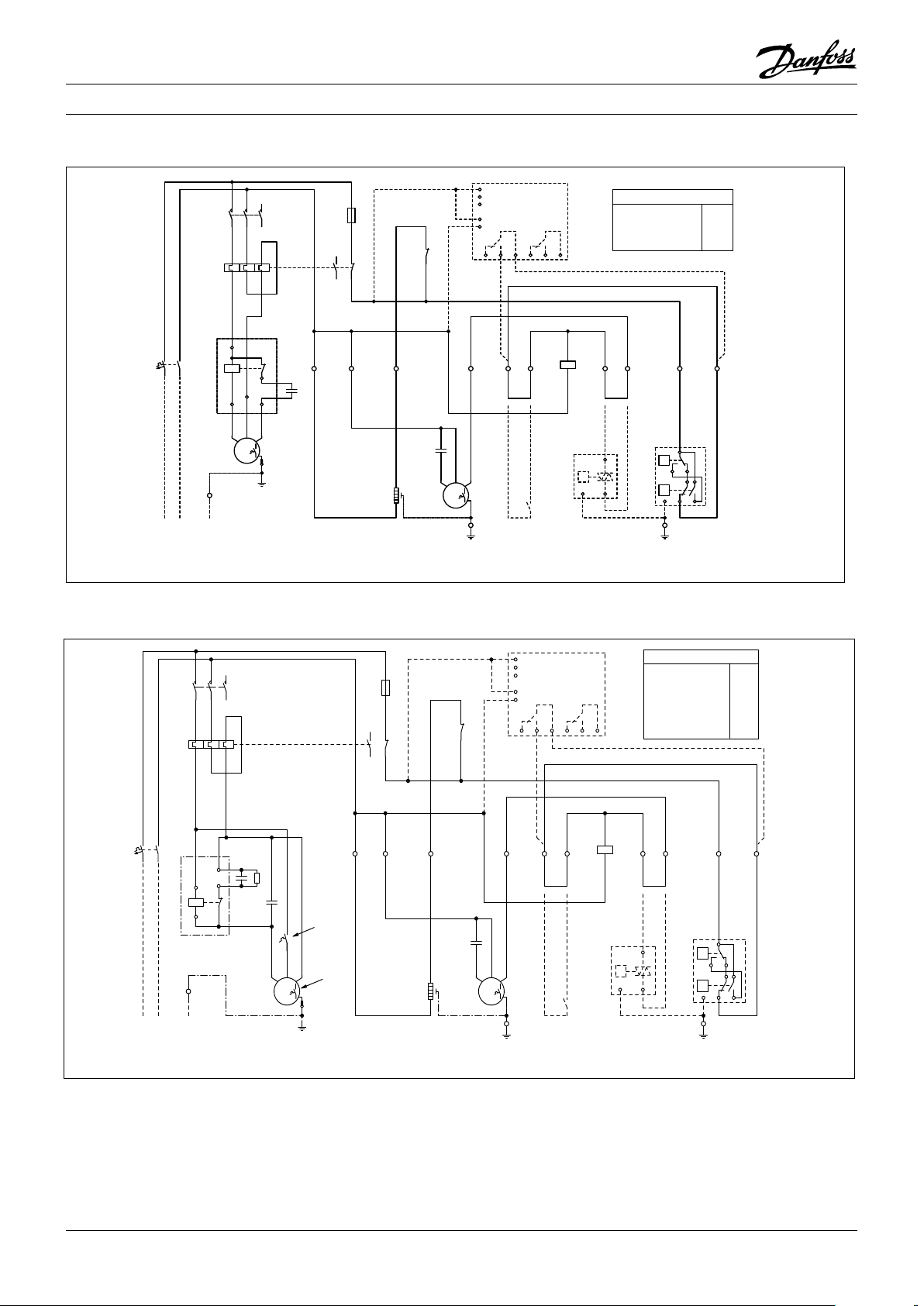
Instrukcje
98
765
4
10
2 3
98
765
4
10
2 3
21
22
-K1
3A
1
2
-F3
95
96
97
98
BK
2 43
BUBNBN
BN
BN
PE
-X1
M
1~
-M2
-S1*
BK BN
1
2
1
-E1
BU
N2 5 6
BN
P
12PE
-B1*
BN
7
BU
BN
BN
8
P<
P>
B
C
A
D
PE
-B2
PE
-X1
BK
N1
-C3
A1
A2
-K1
MG73BF
SM500
16 18 15
L1
L2
L3
P
N
26 28 25
-A1*
M
1~
SCR
PE
-M1
12345
6
-K1
xxA
56341
2
-F2
-C2
-C1
-R1
BN
BU
5
2
1
44
5
-K2
BLBKBR
-F4
OP-.......AJW05G
OP-......SCW05G
BN
-F1
BU
230V1N~/50Hz
L PEN
PE
-X1
OP-......FHW05G
6,7AOP-MSHM018SCW05G
OP-LSHM026AJW05G
OP-LSHM034AJW05G
OP-LSHM048NTW05G
OP-LSHM068NTW05G
OP-LSHM074FHW05G
7,9A
10A
11A
17A
13A
15A
OP-MSHM026AJW05G
OP-MSHM034AJW05G
OP-MSHM024AJW05G 10A
-F2
24A
Kod G : OP-MSHM010- 012 - 015, OP-LSHM015 - 018
1
-F3
3A
2
95
97
98
96
.
.
N2
N1
BU
BK
-F1
12345
-K1
-F2
xxA
-K2
BU
BN
6
56341
2
BU
BN
10
11
14
12
-C2
13
13
-A1*
L1
SM500
L2
L3
MG73BF
P
21
-K1
22
.
1
BK BN
16 18 15
.
2
BK
N
26 28 25
BN
BN
.
A1
-K1
4.3
A2
BN
OP-MSHM010SCW05G
OP-MSHM012SCW05G
OP-MSHM015SCW05G
OP-LSHM015SCW05G
OP-LSHM018SCW05G
.
5.6
-F2
5,3A
6,3A
6,8A
5,5A
5,8A
BN
BN
.
.
7
8
BU
BN
.
-X1
L PEN
230V1N~/50Hz
-M1
PE
S C R
M
1~
PE
-E1
-C3
BUBNBN
1
2
-M2
1~
M
-X1
.
PE
Kod G : OP-LSHM026 - 034 - 048 - 068 - 074, OP-MSHM018 - 024 - 026 - 034
-S1*
-B1*
P
12PE
-B2
A
P<
B
P>
D
C
PE
.
-X1
PE
Legenda
BK czarny
BU niebieski
BN brązowy
GY szary
RD czerwony
WH biały
18 FRCC.EI.026.A5.49 © Danfoss Commercial Compressors 09/14
A1* Przekaźnik nadzoru napięcia (opcja)
B1* Regulator prędkości wentylatora (opcja)
B2 Presostat wysokiego i niskiego ciśnienia
C1 Kondensator pracy (sprężarka)
C2 Kondensator rozruchowy (sprężarka)
C3 Kondensator pracy (wentylator)
E1 Grzałka karteru sprężarki
F1, F3 Bezpiecznik (obwód sterowania)
F2 Przekaźnik przeciążeniowy
F4 Zabezpieczenie termiczne sprężarki
M1 Sprężarka
M2 Silnik wentylatora
K1 Stycznik
K2 Przekaźnik rozruchowy
R1 Rezystor upływowy
S1* Termostat komorowy (opcja)
X1 Zaciski
* Opcja (usunąć mostek)
Page 19
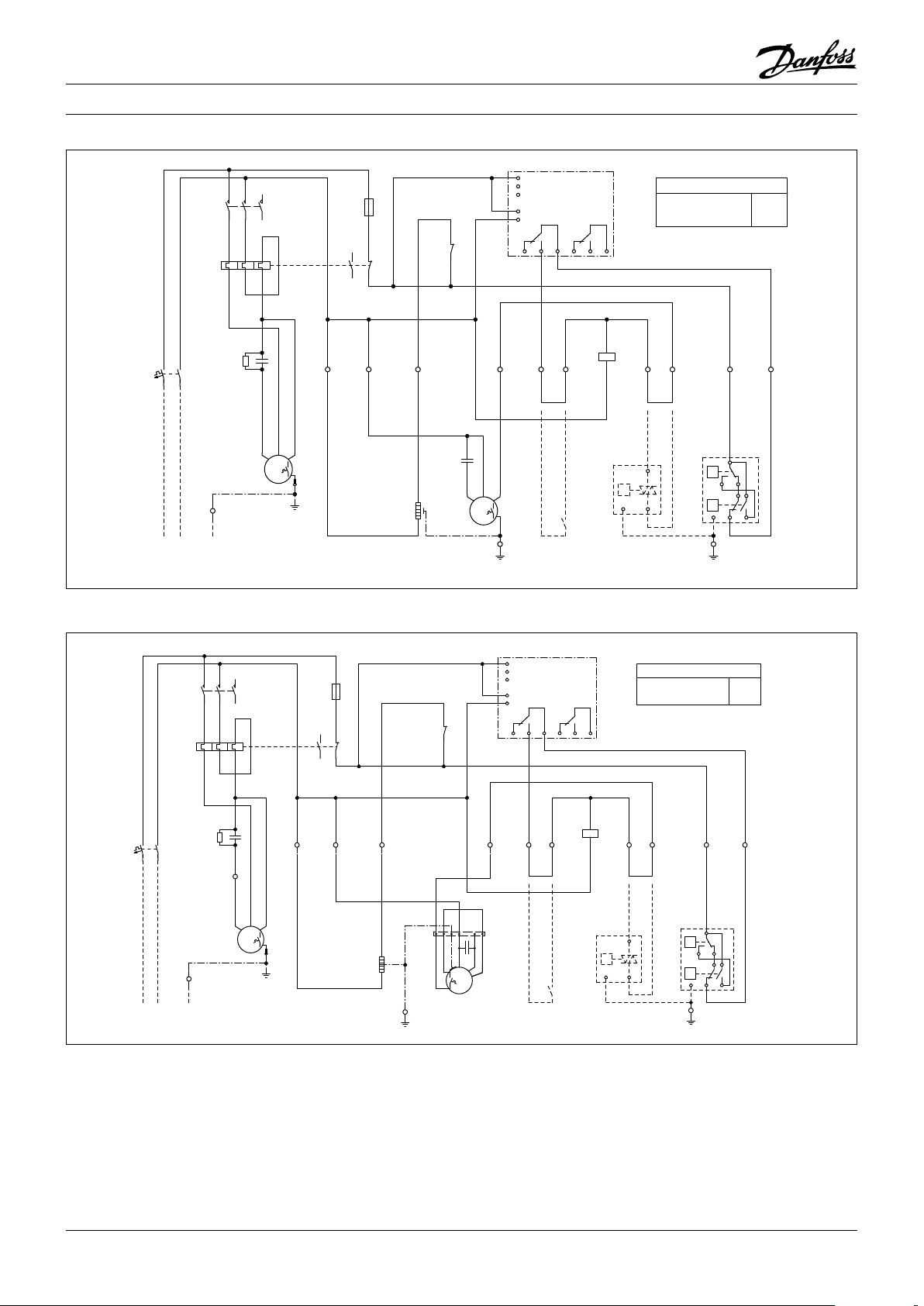
Instrukcje
98
765
4
10
2 3
98
765
4
10
2
3
2 4
3
BN
BN
BN
A1
A2
-K1
MG73BF
SM500
16 18 15
L1
L2
L3
P
N
26 28 25
-A1
-S1*
21
22
-K1
5 6
BN
P
12PE
-B1*
BN
7
BU
BN
BN
8
P<
P>
B
C
A
D
PE
-B2
PE
-X1
-F2
OP-MSUM068MLW05G
OP-MSUM080MLW05G
32A
38A
BKBUBN
WH
WH
1~
M
GNYE
-M2
BK BN
1
BK
N1
N2
3A
1
2
-F3
95
96
97
98
BK
BN
-C1
-R1
GY
M
1~
SCR
PE
-M1
12345
6
-K1
xxA
56341
2
-F2
BU
BN
BN
-F1
BU
PE
-X1
230V1N~/50Hz
L PEN
S
-X1
BU
PE
-X1
2
1
-E1
BN
-C3
Kod G : OP-MSUM034 - 046 - 057
12345
-K1
-F2
xxA
2
BN
BU
BN
-F1
-X1
L PEN
230V1N~/50Hz
-C1
-R1
-M1
PE
6
56341
BU
BK
BN
S C R
M
1~
-A1
L1
SM500
2 4
BK
M
PE
L2
L3
P
N
16 18 15
BN
3
MG73BF
26 28 25
-K1
BN
-S1*
A1
A2
-B1*
5 6
BN
P
12PE
1
-F3
3A
2
95
97
98
96
N1
N2
BK
BU
GY
21
-K1
22
1
BK BN
-C3
PE
-E1
BUBNBN
1
-M2
2
1~
-X1
-F2
OP-MSUM034MLW05G
OP-MSUM046MLW05G
OP-MSUM057MLW05G
BN
BN
-B2
A
P<
B
P>
PE
-X1
PE
19A
25A
26A
BN
7
8
BU
D
C
Kod E : OP-MSUM068 - 080
Legenda
BK czarny
BU niebieski
BN brązowy
GY szary
RD czerwony
WH biały
A1* Przekaźnik nadzoru napięcia (opcja)
B1* Regulator prędkości wentylatora (opcja)
B2 Presostat wysokiego i niskiego ciśnienia
C1 Kondensator pracy (sprężarka)
C2 Kondensator rozruchowy (sprężarka)
C3 Kondensator pracy (wentylator)
E1 Grzałka karteru sprężarki
F1, F3 Bezpiecznik (obwód sterowania)
F2 Przekaźnik przeciążeniowy
F4 Zabezpieczenie termiczne sprężarki
M1 Sprężarka
M2 Silnik wentylatora
K1 Stycznik
K2 Przekaźnik rozruchowy
R1 Rezystor upływowy
S1* Termostat komorowy (opcja)
X1 Zaciski
* Opcja (usunąć mostek)
19FRCC.EI.026.A5.49 © Danfoss Commercial Compressors 09/14
Page 20
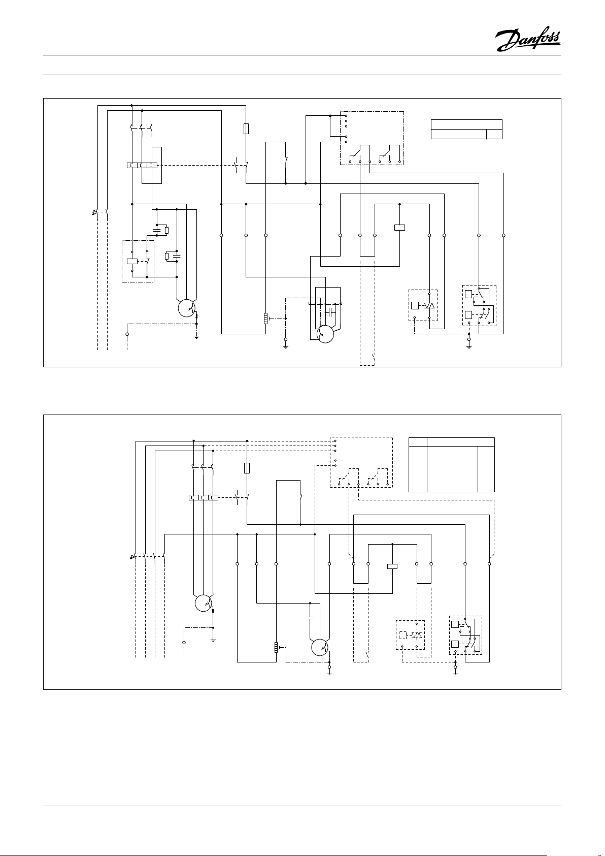
Instrukcje
98
765
4
10
2 3
43
BN
BN
BN
A1
A2
-K1
BK
2
BKBUBN
WH
WH
1~
M
GNYE
-M2
21
22
-K1
95
96
97
98
3A
1
2
-F3
BK BN
1
BKN1BU
N2
MG73BF
SM500
16 18 15
L1
L2
L3
P
N
26 28 25
-A1
PE
-X1
2
1
-E1
-C3
12345
6
-K1
xxA
56341
2
-F2
BU
BN
BKBNBU
-C2
M
1~
SCR
PE
-M1
-R1
-C1
-R2
5
2
1
5
-K2
-S1*
BN
-F1
BU
230V1N~/50Hz
L PEN
PE
-X1
5 6
BN
P
21PE
-B1
BN
7
BU
BN
BN
8
PE
-X1
P<
P>
B
C
A
D
PE
-B2
-F2
40AOP-MSUM093MLW06G
98
765
4
10
2 3
Kod G : OP-MSUM093
Kod E : OP-LSHM048 - 068 - 074, OP-MSHM026 - 034, OP-MSUM034 - 046 - 057
-A1*
L1
L2
BUBNBN
M
1~
-X1
L3
P
N
16 18 15
2 43
BK
PE
12345
-K1
-F2
xxA
BNBKGY
1234567
-F1
BU
8
L1 L2 PEL3 N
380-400V3N~/50Hz
-M1
-X1
PE
6
56341
2
BKGYBN
M
3~
-F3
1
3A
2
95
97
98
96
-K1
21
22
BN
1N2N1 5 6
BK
BU
BK
-C3
-E1
1
-M2
2
SM500
MG73BF
26 28 25
BN
BN
-S1*
-K1
-A1* -F2
--OP-MSHM026AJW05E
X
X
X
-
-
-
A1
A2
BN
-B1*
P
OP-MSHM034AJW05E
OP-MSUM034MLW05E
OP-MSUM046MLW05E
OP-MSUM057MLW05E
OP-LSHM048NTW05E
OP-LSHM068NTW05E
OP-LSHM074FHW05E 7,9A
-B2
A
P<
B
-X1
P>
PE
PE
12PE
4,0A
4,8A
7,0A
9,5A
10A
4,8A
8,4A
BN
BN
7
8
BU
BN
D
C
Legenda
BK czarny
BU niebieski
BN brązowy
GY szary
RD czerwony
WH biały
20
A1* Przekaźnik nadzoru napięcia (opcja)
B1* Regulator prędkości wentylatora (opcja)
B2 Presostat wysokiego i niskiego ciśnienia
C3 Kondensator pracy (wentylator)
E1 Grzałka karteru sprężarki
F1, F3 Bezpiecznik (obwód sterowania)
F2 Przekaźnik przeciążeniowy
F4 Zabezpieczenie termiczne sprężarki
FRCC.EI.026.A5.49 © Danfoss Commercial Compressors 09/14
M1 Sprężarka
M2 Silnik wentylatora
K1 Stycznik
K2 Przekaźnik rozruchowy
R1 Rezystor upływowy
S1* Termostat komorowy (opcja)
X1 Zaciski
* Opcja (usunąć mostek)
Page 21
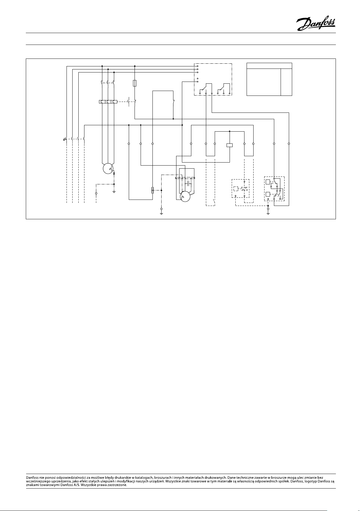
Instrukcje
98
765
4
10
2
3
BN
-S1*
BN
P
12PE
-B1*
BU
BN
PE
-X1
P<
P>
B
C
A
D
PE
-B2
2 4
3
BN
BN
5
6
BN
7
BN
8
-F2
21
22
-K1
A1
A2
-K1
MG73BF
SM500
16 18 15
L1
L2
L3
P
N
26 28 25
-A1
13A
15A
16A
15A
OP-MSUM068MLW05E
OP-MSUM080MLW05E
OP-MSUM099MLW05E
OP-MSUM108MLW05E
OP-LSHM067LLW05E
OP-LSHM084LLW05E
OP-LSHM098LLW05E
12A
15A
15A
BKBUBN
WH
WH
1~
M
GNYE
-M2
3A
1
2
-F3
95
96
97
98
12345
6
-K1
BKGYBN
M
3~
-M1
xxA
56341
2
-F2
BK
BU
BK
BN
1
N2
N1
BNBKGY
BU
PE
-X1
380-400V3N~/50Hz
L1 L2 PEL3 N
1234567
8
-F1
2
1
-E1
PE
-X1
BN
-C3
Kod E : OP-LSHM084 - 098, OP-MSUM068 - 080 - 099 - 108
Legenda
BK czarny
BU niebieski
BN brązowy
GY szary
RD czerwony
WH biały
A1* Przekaźnik nadzoru napięcia (opcja)
B1* Regulator prędkości wentylatora (opcja)
B2 Presostat wysokiego i niskiego ciśnienia
C1 Kondensator pracy (sprężarka)
C2 Kondensator rozruchowy (sprężarka)
C3 Kondensator pracy (wentylator)
E1 Grzałka karteru sprężarki
F1, F3 Bezpiecznik (obwód sterowania)
F2 Przekaźnik przeciążeniowy
FRCC.EI.026.A5.49 — September 2014 Copyright Danfoss Commercial Compressors — DSS — 09/14
F4 Zabezpieczenie termiczne sprężarki
M1 Sprężarka
M2 Silnik wentylatora
K1 Stycznik
K2 Przekaźnik rozruchowy
R1 Rezystor upływowy
S1* Termostat komorowy (opcja)
X1 Zaciski
* Opcja (usunąć mostek)
Page 22

118UXXXX
INSTRUCCIONES
OPTYMA™ SLIM PACK OP-LSHM/MSUM/MSHM
L
MADE IN INDIA
A
OP-MSUM034MLW05E
Code no.:
B
Application
C
Refrigerant
D
M.W.P. HP
E
LP (1) 7 bar
Voltage 380-400V3N~/50Hz
F
LRA 30,5 7,5MCC
Serial No.
G
Barcode Serial No:
114X7062
MBP
(1) R404A, R507A
(1) 28 bar
123456CG0514
IP54
(2) R134a
(2) 23 bar
(2) 5 bar
A: Modelo.
B: Código.
C
: Aplicación e ínidce de protección.
D: Refrigerante.
E: Presión de servicio de la carcasa.
F: Tensión de alimentación, intensidad a rotor
bloqueado (LRA) y máxima intensidad en
funcionamiento continuo (MCC).
G: Número de serie y código de barras.
Ilustración 2
H
I
J
H: Conexiones de entrada de cables.
I: Conexión de aspiración.
J: Conexión de la línea de líquido.
K: Intercambiador de calor de microcanales.
Ilustración 3
Tornillos de montaje
(no suministrados)
N
M
K
Ilustración 1: Distancias de montaje mínimas
L
[mm]
250 650 550 550
M
[mm]
N
[mm]
La instalación y el mantenimiento de
la unidad condensadora deben ser
llevados a cabo exclusivamente por
personal cualicado. Siga estas instrucciones
y las prácticas recomendadas en materia
de ingeniería de refrigeración durante las
actividades de instalación, puesta en servicio,
mantenimiento y servicio técnico.
El uso de la unidad condensadora sólo debe
llevarse a cabo para los nes para los que ha sido
diseñada y dentro de su campo de aplicación.
En cualquier circunstancia, han de cumplirse
los requisitos establecidos por la norma EN378
(o cualquier otro reglamento local vigente en
materia de seguridad).
Esta unidad condensadora se suministra con
gas nitrógeno a presión (1 bar) y, por lo tanto, no puede conectarse tal cual; consulte la
sección “Instalación” para obtener más información.
Manipule la unidad condensadora con precaución y en posición vertical (desviación
máxima respecto a la vertical: 15°).
O
O
[mm]
1 – Introducción
Estas instrucciones pertenecen a las unidades condensadoras Optyma™ Slim Pack OP-LSHM/MSUM/MSHM
(para refrigerantes R-507A, R-404A, R-134a y R-22), diseñadas para sistemas de refrigeración. Incluyen la información necesaria para garantizar la seguridad y el
uso correcto del producto.
Estas unidades condensadoras incluyen los siguientes
componentes:
• Compresor scroll/alternativo.
• Intercambiador de calor de microcanales.
• Presostatos dobles.
• Válvulas de servicio (líneas de aspiración y líquido).
• Carcasa hermética.
• Filtro secador.
• Resistencia de cárter para el compresor.
• Recipiente con válvula de cierre.
• Visor de líquido.
• Relé de secuencia de fases (
• Panel eléctrico totalmente precableado (incluye interruptor principal, contactor para compresor y relé
de sobrecarga).
2 – Manipulación y almacenamiento
• Se recomienda no abrir el embalaje hasta que la unidad se encuentre en el lugar en el que se vaya a proceder a su instalación.
• Manipule la unidad con cuidado. El embalaje admite
el uso de una carretilla elevadora o una transpaleta
para su manipulación. Use siempre equipos de ele
vación adecuados y seguros.
• Almacene y transporte la unidad en posición vertical.
• Almacene la unidad a temperaturas comprendidas
entre -35 °C y 50 °C.
compresor scroll).
• No exponga el embalaje a la lluvia o a atmósferas de
carácter corrosivo.
• Tras desembalar la unidad, compruebe que no falte
ningún componente y que no presente daños.
3 – Medidas a adoptar de cara a la instalación
No realice ningún tipo de soldadura mientras la uni-
dad condensadora se encuentre presurizada.
No coloque nunca la unidad en una atmósfera de
carácter inamable.
Coloque la unidad de forma que no obstruya u obstaculice vías de paso, puertas, ventanas u otros elementos similares.
• Asegúrese de que exista espacio suciente alrededor
de la unidad para permitir la circulación del aire y la apertura
de las puertas. Consulte la ilustración 1 para co-
nocer las distancias mínimas con respecto a las paredes.
• No instale la unidad en ubicaciones en las que se vea
expuesta a la luz solar directa a diario durante perío
dos prolongados.
• No instale la unidad en atmósferas de carácter agre
sivo o polvoriento.
• Disponga una supercie de cimentación horizontal
(con una pendiente inferior a 3°), robusta y estable
que sirva para soportar el peso del conjunto de la
unidad y eliminar las vibraciones e interferencias.
• La temperatura ambiente de la unidad no debe su
perar los 50 °C durante el ciclo de apagado.
• Asegúrese de que la fuente de alimentación sea
compatible con los requisitos de la unidad (consulte
la placa de características).
• La instalación de unidades destinadas al uso con refrigerantes HFC requiere del empleo de equipos diseñados especícamente para tales refrigerantes y
que no hayan permanecido en contacto con refrigerantes CFC o HCFC.
• Use tubos de cobre para refrigeración limpios y deshidratados y aleaciones de plata como material de
soldadura.
• Use componentes de sistema limpios y deshidratados.
• La tubería de aspiración conectada al compresor
debe ser exible en las 3 dimensiones para amortiguar las vibraciones. Además, la tubería debe disponerse de tal forma que el retorno de aceite hacia el
compresor esté garantizado y que el riesgo de que se
produzcan golpes de líquido en el compresor se elimine.
4 – Instalación
• La instalación en la que se coloque la unidad condensadora debe cumplir los requisitos de la Directiva 97/23/CE de equipos a presión (DEP). En sí, la unidad condensadora no tiene la consideración de
“unidad” en el campo de aplicación de dicha directiva.
• La unidad se debe instalar de forma segura en un
soporte estable y rígido al que se deberá jar desde
un principio. Consulte la ilustración 2.
• Se recomienda instalar la unidad sobre arandelas
-
de caucho o elementos que amortigüen las vibraciones (no se incluyen entre los componentes suministrados).
• Libere paulatinamente la carga de nitrógeno a través
del puerto Schraeder.
• Conecte la unidad al sistema lo antes posible para
evitar que el aceite sufra contaminación como resul-
tado de la humedad ambiental.
• Evite que penetren materiales extraños en el sistema
durante el corte de los tubos. No practique oricios en
lugares en los que no sea posible eliminar las rebabas.
• Lleve a cabo las soldaduras con cuidado, empleando
técnicas modernas; purgue los conductos haciendo
circular gas nitrógeno.
• Conecte los dispositivos de seguridad y control ne
22
FRCC.EI.026.A5.05 © Danfoss Commercial Compressors 09/14
Page 23

Instrucciones
cesarios. Retire la válvula interna cuando use el puer-
to Schraeder a este efecto.
• Se recomienda aislar la tubería de aspiración hasta la
entrada del compresor empleando material aislante
con un espesor de 19 mm.
5 – Detección de fugas
No presurice el circuito con oxígeno o aire seco. Esto
podría dar lugar a incendios o explosiones.
• No use tintes para la detección de fugas.
• Lleve a cabo una prueba de detección de fugas en
todo el sistema.
• La presión de prueba máxima es de 32 bar.
• Si detecta una fuga, repárela y lleve a cabo una nueva prueba de detección de fugas.
6 – Deshidratación por vacío
• No use el compresor para vaciar el sistema.
• Conecte una bomba de vacío a los lados LP y HP.
• Vacíe el sistema a una presión absoluta de 500 μm
Hg (0,67 mbar).
• No use un ohmímetro ni conecte la alimentación al
compresor mientras este se encuentre sometido a
vacío; ello podría causar daños internos.
7 – Conexiones eléctricas
• Apague el sistema y aísle la fuente de alimentación
principal.
• Asegúrese de que la fuente de alimentación no pueda
encenderse durante la instalación.
• La elección de los componentes eléctricos debe llevarse
a cabo de acuerdo con las normas locales y los requisitos
de la unidad.
• Consulte el esquema eléctrico para obtener más información sobre las conexiones eléctricas.
• Compruebe que la fuente de alimentación sea compatible con las características de la unidad y que
ofrezca un suministro estable (tensión nominal ±10 %
y frecuencia nominal ±2,5 Hz).
• Calcule las dimensiones de los cables de la fuente de
alimentación en función de la tensión y la corriente
de la unidad.
• Proteja la fuente de alimentación y asegúrese de que
disponga de una conexión a tierra adecuada.
• Conecte la fuente de alimentación de acuerdo con
las normas locales y los requisitos legales vigentes.
La unidad está equipada con presostatos de alta y baja
•
presión que interrumpen directamente el suministro
eléctrico del compresor al activarse. Los parámetros
de desconexión por alta y baja presión deben ser ajus
tados por el instalador considerando el modelo del
compresor, el refrigerante y la aplicación. Las unidades
con compresores MLZ, LLZ y NTZ de Danfoss también
están equipadas con relé de secuencia de fases como
medida de protección contra la pérdida, el error de
secuencia y la asimetría de fases, así como frente a
efectos de subtensión y sobretensión.
En el caso de las unidades con compresor scroll trifási-
co, se deberá respetar la secuencia de fases correcta a
n de que el compresor gire en el sentido apropiado.
• Emplee un medidor de fases para establecer el orden
de las fases de línea (L1, L2 y L3).
• Conecte las fases de línea L1, L2 y L3 a los terminales
T1, T2 y T3 del interruptor principal, respectivamente.
8 – Llenado del sistema
• Utilice los equipos de protección oportunos, como
gafas y guantes de seguridad.
• No ponga en marcha el compresor en condiciones
de vacío. Mantenga el compresor apagado.
• Antes de cargar el refrigerante, compruebe que el
nivel de aceite se encuentre entre las marcas “¼” y
“¾” del visor de aceite del compresor. Si es necesario
añadir aceite, consulte la etiqueta del compresor
para conocer el tipo de aceite que debe emplearse.
• Utilice exclusivamente el refrigerante para el que se
haya diseñado la unidad.
• Llene el condensador o el recipiente de líquido con
refrigerante líquido. Asegúrese de que la carga del
sistema tenga lugar paulatinamente hasta alcanzar
una presión de 4-5 bar (en el caso de los refrigerantes R-404A/R-507A y R-22) o aprox. 2 bar (en el caso
del refrigerante R-134a).
• No introduzca refrigerante líquido a través de la línea
de aspiración.
• Se prohíbe la mezcla de aditivos con el aceite y/o el
refrigerante.
• La carga restante se efectuará hasta que la instalación alcance las condiciones de funcionamiento nominales y estas se mantengan estables.
• No deje la botella de carga conectada al circuito.
9 – Verificación previa a la puesta en servicio
Emplee dispositivos de seguridad (como presostatos de seguridad o válvulas mecánicas de alivio) que
satisfagan los requisitos de las normas de ámbito general y local vigentes, así como las normas de seguridad
aplicables. Asegúrese de que los dispositivos funcionen y su ajuste sea correcto.
Compruebe que los niveles de los presostatos de
alta presión y las válvulas de alivio no superen la presión de servicio máxima de los componentes del sistema.
• Compruebe que todas las conexiones eléctricas se
encuentren bien jadas y cumplan las normas locales.
Si es preciso el uso de una resistencia de cárter, esta de-
•
berá energizarse, al menos, 12horas antes de la puesta
en marcha inicial y cualquier puesta en marcha que ten
ga lugar tras un período prolongado de inactividad.
10 – Arranque
• No arranque la unidad sin haber cargado antes el
refrigerante.
• Todas las válvulas de servicio deben estar en posi-
ción de apertura. Consulte la ilustración 3.
• Compruebe que la unidad y la fuente de alimenta-
ción sean compatibles.
• Compruebe que la resistencia de cárter se encuentre
en funcionamiento.
• Compruebe que el ventilador pueda girar libremente.
• Compruebe que se haya retirado la chapa de protec-
ción de la parte posterior del condensador.
• Equilibre las presiones de los lados HP y LP.
• Ponga en marcha la unidad. Debe arrancar de inme-
diato. Si el compresor no se pone en marcha, compruebe que los cables sean adecuados, así como la
tensión en los terminales y la secuencia de fases.
• El giro en sentido inverso de un compresor trifásico
se puede detectar a través de los siguientes síntomas: la unidad no se pone en marcha, no se acumula
presión en el compresor, el nivel de ruido es anormalmente alto o el consumo de potencia es anormalmente bajo. Si detecta alguno de dichos síntomas, detenga la unidad de manera inmediata y
conecte correctamente las fases a sus terminales correspondientes.
• Si la dirección de rotación es correcta, el manómetro
de baja presión deberá indicar una disminución de la
presión y el manómetro de alta presión deberá indicar
un aumento de presión.
11 – Comprobaciones con la unidad en funcionamiento
• Compruebe el sentido de giro del ventilador. Debe
circular aire desde el condensador hacia el ventilador.
• Compruebe el consumo de corriente y la tensión.
• Compruebe el recalentamiento en el lado de aspiración para reducir el riesgo de generación de golpes
de líquido.
• Si la unidad incorpora un visor de líquido, controle el
nivel de aceite durante la puesta en marcha y el funcionamiento para conrmar que permanece dentro
del rango visible.
• Respete los límites de funcionamiento.
• Compruebe si los tubos sufren alguna vibración anormal.
Los movimientos superiores a 1,5 mm exigirán la implantación de medidas correctoras (como la instalación de abrazaderas).
• Si es necesario, se puede agregar refrigerante líquido
a través del lado de baja presión (tan lejos del compresor como sea posible). El compresor debe permanecer en funcionamiento durante este proceso.
• No sobrecargue el sistema.
• No libere refrigerante a la atmósfera.
• Antes de abandonar el lugar de instalación, lleve a
cabo una inspección general de la misma en cuanto
a limpieza, ruido y detección de fugas.
• Anote el tipo y la cantidad de refrigerante cargado,
así como las condiciones de funcionamiento, como
referencia para la ejecución de futuras inspecciones.
12 – Mantenimiento
Desconecte siempre la unidad utilizando el inte-
rruptor principal antes de desmontar el panel del ventilador.
Las presiones internas y las temperaturas superciales de la unidad son peligrosas y pueden dar lugar a
lesiones permanentes.
Los técnicos de mantenimiento y los instaladores deben disponer de la formación y las herramientas apropiadas. La temperatura de los tubos puede superar los
100 °C, como resultado de lo cual podrían producirse
quemaduras de carácter grave.
Asegúrese de que se realicen las inspecciones de
servicio periódicas necesarias para garantizar la abilidad del sistema, de acuerdo con lo dispuesto en la legislación local vigente.
Para evitar que se produzcan problemas en el sistema,
se recomienda
llevar a cabo periódicamente las siguientes operaciones de mantenimiento:
• Comprobar que los dispositivos de seguridad fun-
cionen y su ajuste sea correcto.
• Garantizar la ausencia de fugas en el sistema.
• Comprobar el consumo de corriente del compresor.
-
• Conrmar que el sistema funcione de modo cohe-
rente con los registros de mantenimiento anteriores
y las condiciones ambientales.
• Comprobar que todas las conexiones eléctricas se
encuentren correctamente jadas.
• Mantener limpia la unidad y comprobar la ausencia
de óxido y herrumbre en los componentes, los tubos
y las conexiones eléctricas de la misma.
El condensador se debe revisar al menos una vez al año
para detectar posibles obstrucciones y proceder a su
limpieza, si es necesario. Se puede acceder a la parte
interna del condensador a través del panel del ventilador. La suciedad tiende a acumularse en la supercie
de los serpentines de los microcanales en lugar de en
su interior, lo que facilita su limpieza en comparación
con los serpentines de tubo y aletas.
• Desconecte la unidad condensadora utilizando el
interruptor principal antes de desmontar cualquier
panel de la misma.
• Elimine la suciedad, las hojas, las bras, etc., de las
supercies empleando una aspiradora a la que se
haya acoplado un cepillo u otro accesorio suave.
También puede realizar un soplado con aire comprimido a través del serpentín (desde su parte interior
hacia su parte exterior) y cepillarlo con un cepillo de
cerdas blandas. No use cepillos de alambre. No golpee ni raye el serpentín con el tubo de vacío o la boquilla de aire.
Si se ha abierto el sistema de refrigerante, este deberá
recorrerse con aire seco o nitrógeno para eliminar la
humedad; asimismo, se deberá instalar
un nuevo ltro secador. Si es necesario evacuar el refrigerante, esta operación se deberá realizar de manera que
ninguna fracción de aquel pueda escapar a la atmósfera.
13 – Garantía
En cualquier reclamación que presente al respecto de
este producto, indique siempre el número de modelo y
el número de serie.
La garantía del producto puede quedar anulada por los
siguientes motivos:
• Ausencia de placa de características.
• Modicaciones externas; en particular, perforacio-
nes, soldaduras, patas rotas y marcas de impactos.
• Apertura del compresor o devolución del mismo sin
los precintos correspondientes.
• Presencia de óxido, agua o tinte de detección de fu-
gas en el interior del compresor.
• Uso de un refrigerante o lubricante no homologado
por Danfoss.
• Cualquier divergencia en relación con las instruccio-
nes recomendadas para su instalación, aplicación o
mantenimiento.
• Uso como parte de aplicaciones móviles.
• Uso en atmósferas de carácter explosivo.
• Omisión del número de modelo o el número de serie
en la reclamación bajo garantía.
14 – Eliminación
Danfoss recomienda que las unidades condensadoras y el aceite empleado para su funcionamiento sean reciclados por una empresa gestora autorizada y en sus instalaciones.
23FRCC.EI.026.A5.05 © Danfoss Commercial Compressors 09/14
Page 24

Instrucciones
98
765
4
10
2 3
98
765
4
10
2 3
Código G : OP-MSHM010- 012 - 015, OP-LSHM015 - 018
1
-F3
3A
2
95
97
98
96
.
.
.
N2
N1
BU
BK
-F1
12345
-K1
-F2
xxA
-K2
BU
BN
6
56341
2
BU
BN
10
11
14
12
13
13
-C1
-A1*
L1
SM500
L2
L3
MG73BF
P
21
-K1
22
1
BK BN
16 18 15
.
2
BK
N
26 28 25
BN
BN
.
A1
-K1
4.3
A2
BN
OP-MSHM010SCW05G
OP-MSHM012SCW05G
OP-MSHM015SCW05G
OP-LSHM015SCW05G
OP-LSHM018SCW05G
.
5.6
-F2
5,3A
6,3A
6,8A
5,5A
5,8A
BN
BN
.
.
7
8
BU
BN
.
-X1
L PEN
230V1N~/50Hz
-M1
PE
S C R
M
1~
PE
-E1
-C3
BUBNBN
1
2
-M2
1~
M
-X1
.
PE
Código G : OP-LSHM026 - 034 - 048 - 068 - 074, OP-MSHM018 - 024 - 026 - 034
-A1*
12345
-K1
-F2
xxA
BU
BN
-F1
-K2
6
56341
2
BN
BU
-R1
44
5
5
1
-C1
2
-C2
OP-.......AJW05G
-F4
BLBKBR
L PEN
-X1
SCR
M
-M1
PE
1~
PE
OP-......SCW05G
OP-......FHW05G
230V1N~/50Hz
1
-F3
3A
2
95
97
98
96
N2 5 6
N1
BU
BK
BK BN
-K1
1
21
22
-C3
BUBNBN
1
-E1
2
-M2
M
1~
-X1
-S1*
L1
L2
L3
P
N
16 18 15
2 43
BK
PE
-B1*
BN
P
SM500
MG73BF
26 28 25
BN
-S1*
12PE
-K1
A1
A2
-B1*
-B2
A
P<
B
P>
D
C
PE
.
-X1
PE
OP-MSHM024AJW05G 10A
OP-MSHM026AJW05G
OP-MSHM034AJW05G
OP-LSHM026AJW05G
OP-LSHM034AJW05G
OP-LSHM048NTW05G
OP-LSHM068NTW05G
OP-LSHM074FHW05G
BN
P
12PE
-F2
-X1
-B2
P<
P>
6,7AOP-MSHM018SCW05G
13A
15A
7,9A
10A
11A
17A
24A
BN
BN
7
8
BU
BN
A
B
D
C
PE
PE
leyenda
BK negro
BU azul
BN marrón
GY gris
RD rojo
WH blanco
A1* Relé de tensión (opcional)
B1* Controlador velocidad del ventilador (opcional)
B2 Presostato de alta & de baja presión
C1 Condensador de funcionamiento (compresor)
C2 Condensador de arranque (compresor)
C3 Condensador de funcionamiento (ventilador)
E1 Resistencia del cárter
F1, F3 Fusible (circuito de control)
F2 Relé de sobrecarga
F4 Compresor protector térmico
M1 Compresor
M2 Motor del ventilador
K1 Contactor
K2 Relé de arranque
R1 Resistencia de absorción
S1* Termostato ambiente (opcional)
X1 Terminales
* Opción (quitar el puente)
24 FRCC.EI.026.A5.05 © Danfoss Commercial Compressors 09/14
Page 25
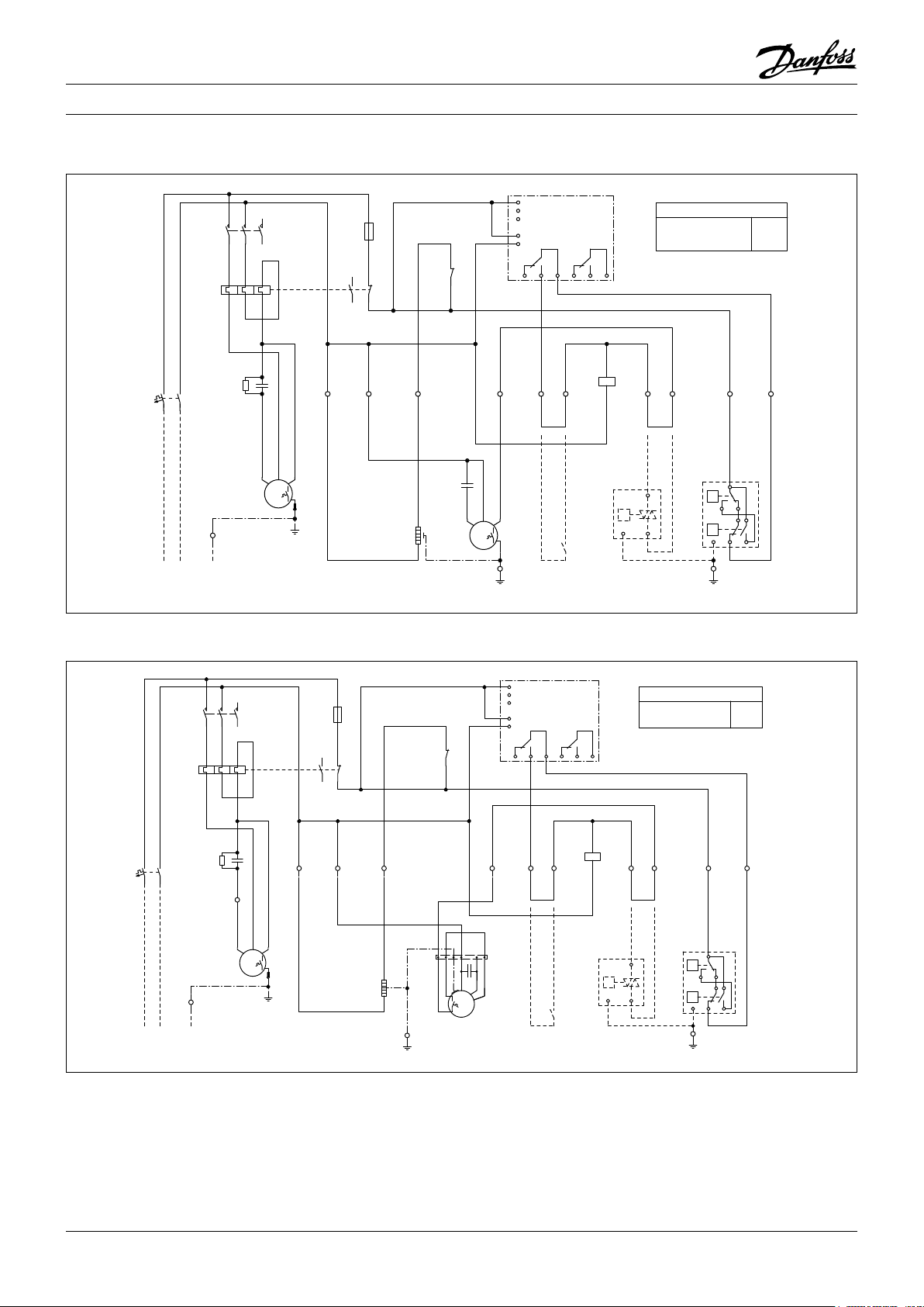
Instrucciones
98
765
4
10
2 3
98
765
4
10
2
3
2 4
3
BN
BN
BN
A1
A2
-K1
MG73BF
SM500
16 18 15
L1
L2
L3
P
N
26 28 25
-A1
-S1*
21
22
-K1
5 6
BN
P
12PE
-B1*
BN
7
BU
BN
BN
8
P<
P>
B
C
A
D
PE
-B2
PE
-X1
-F2
OP-MSUM068MLW05G
OP-MSUM080MLW05G
32A
38A
BKBUBN
WH
WH
1~
M
GNYE
-M2
BK BN
1
BK
N1
N2
3A
1
2
-F3
95
96
97
98
BK
BN
-C1
-R1
GY
M
1~
SCR
PE
-M1
12345
6
-K1
xxA
56341
2
-F2
BU
BN
BN
-F1
BU
PE
-X1
230V1N~/50Hz
L PEN
S
-X1
BU
PE
-X1
2
1
-E1
BN
-C3
Código G : OP-MSUM034 - 046 - 057
12345
BU
BN
-F1
-X1
L PEN
230V1N~/50Hz
-K1
-F2
xxA
PE
2
BN
-R1
-C1
-M1
6
56341
BU
BK
S C R
M
1~
-A1
L1
SM500
2 4
BK
M
PE
L2
L3
P
N
16 18 15
BN
3
MG73BF
26 28 25
-K1
BN
-S1*
A1
A2
-B1*
5 6
BN
P
12PE
1
-F3
3A
2
95
97
98
96
N1
N2
BK
BU
BN
GY
21
-K1
22
1
BK BN
-C3
PE
-E1
BUBNBN
1
-M2
2
1~
-X1
-F2
OP-MSUM034MLW05G
OP-MSUM046MLW05G
OP-MSUM057MLW05G
BN
BN
-B2
A
P<
B
P>
PE
-X1
PE
19A
25A
26A
BN
7
8
BU
D
C
Código G : OP-MSUM068 - 080
leyenda
BK negro
BU azul
BN marrón
GY gris
RD rojo
WH blanco
A1* Relé de tensión (opcional)
B1* Controlador velocidad del ventilador (opcional)
B2 Presostato de alta & de baja presión
C1 Condensador de funcionamiento (compresor)
C2 Condensador de arranque (compresor)
C3 Condensador de funcionamiento (ventilador)
E1 Resistencia del cárter
F1, F3 Fusible (circuito de control)
F2 Relé de sobrecarga
F4 Compresor protector térmico
M1 Compresor
M2 Motor del ventilador
K1 Contactor
K2 Relé de arranque
R1 Resistencia de absorción
S1* Termostato ambiente (opcional)
X1 Terminales
* Opción (quitar el puente)
25FRCC.EI.026.A5.05 © Danfoss Commercial Compressors 09/14
Page 26
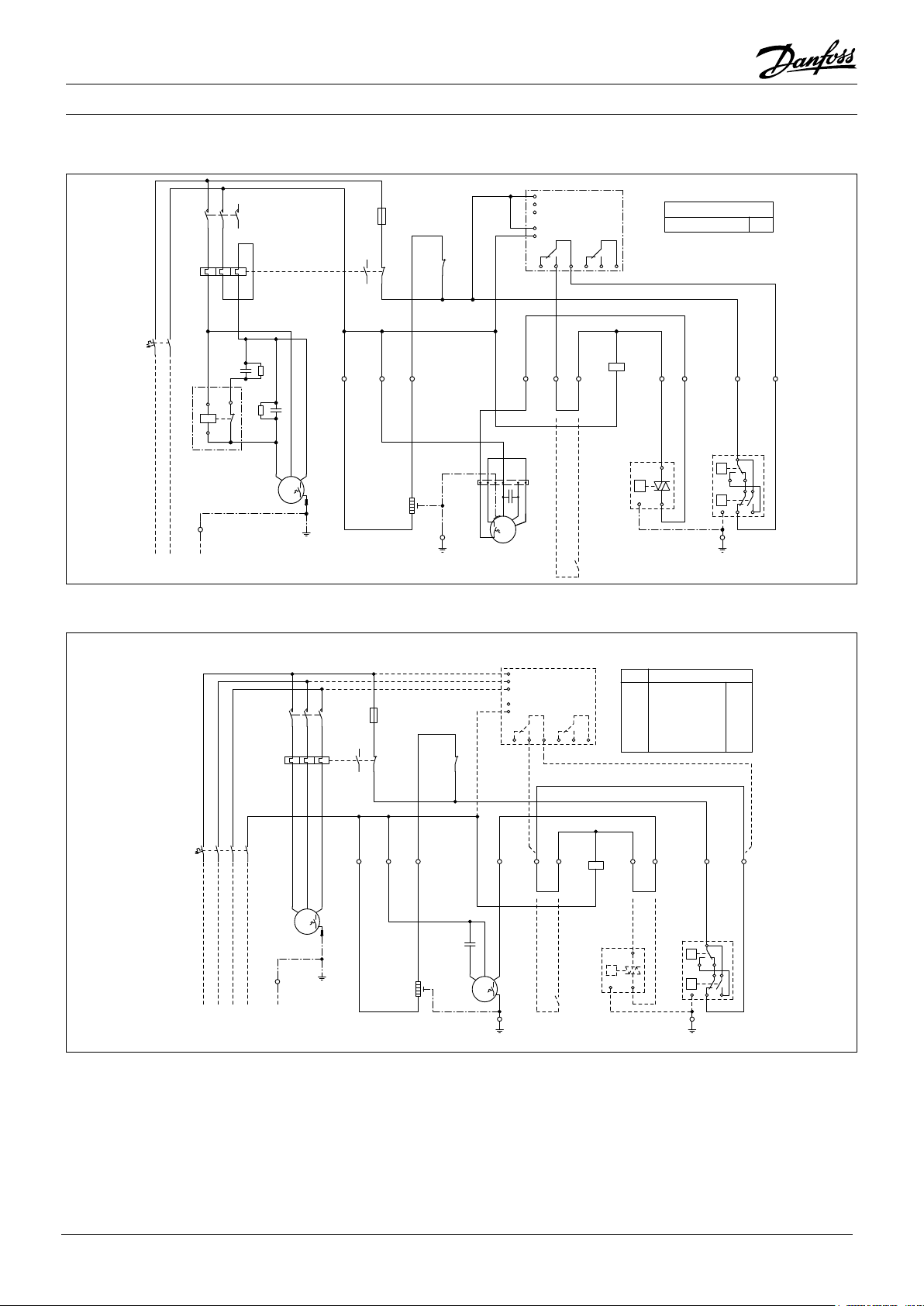
Instrucciones
98
765
4
10
2 3
43
BN
BN
BN
A1
A2
-K1
BK
2
BKBUBN
WH
WH
1~
M
GNYE
-M2
21
22
-K1
95
96
97
98
3A
1
2
-F3
BK BN
1
BKN1BU
N2
MG73BF
SM500
16 18 15
L1
L2
L3
P
N
26 28 25
-A1
PE
-X1
2
1
-E1
-C3
12345
6
-K1
xxA
56341
2
-F2
BU
BN
BKBNBU
-C2
M
1~
SCR
PE
-M1
-R1
-C1
-R2
5
2
1
5
-K2
-S1*
BN
-F1
BU
230V1N~/50Hz
L PEN
PE
-X1
5 6
BN
P
21PE
-B1
BN
7
BU
BN
BN
8
PE
-X1
P<
P>
B
C
A
D
PE
-B2
-F2
40AOP-MSUM093MLW06G
98
765
4
10
2 3
Código G : OP-MSUM093
Código E : OP-LSHM048 - 068 - 074, OP-MSHM026 - 034, OP-MSUM034 - 046 - 057
-A1*
L1
SM500
L2
L3
12345
-K1
-F2
xxA
-F1
BNBKGY
1234567
BU
8
-X1
L1 L2 PEL3 N
-M1
PE
2
6
56341
BKGYBN
M
3~
380-400V3N~/50Hz
-F3
3A
1
2
95
97
98
96
BU
BK
-E1
21
-K1
22
BN
1N2N1 5 6
BK
-C3
1
-M2
2
BUBNBN
M
1~
BK
-X1
P
N
16 18 15
2 43
PE
MG73BF
26 28 25
BN
BN
-S1*
-K1
-A1* -F2
--OP-MSHM026AJW05E
X
X
X
-
-
-
A1
A2
BN
-B1*
P
OP-MSHM034AJW05E
OP-MSUM034MLW05E
OP-MSUM046MLW05E
OP-MSUM057MLW05E
OP-LSHM048NTW05E
OP-LSHM068NTW05E
OP-LSHM074FHW05E 7,9A
-B2
P<
-X1
P>
PE
PE
12PE
4,0A
4,8A
7,0A
9,5A
10A
4,8A
8,4A
BN
BN
7
8
BU
BN
A
B
D
C
A1* Relé de tensión (opcional)
B1* Controlador velocidad del ventilador (opcional)
B2 Presostato de alta & de baja presión
C3 Condensador de funcionamiento (ventilador)
E1 Resistencia del cárter
F1, F3 Fusible (circuito de control)
F2 Relé de sobrecarga
F4 Compresor protector térmico
leyenda
BK negro
BU azul
BN marrón
GY gris
RD rojo
WH blanco
26 FRCC.EI.026.A5.05 © Danfoss Commercial Compressors 09/14
M1 Compresor
M2 Motor del ventilador
K1 Contactor
K2 Relé de arranque
R1 Resistencia de absorción
S1* Termostato ambiente (opcional)
X1 Terminales
* Opción (quitar el puente)
Page 27
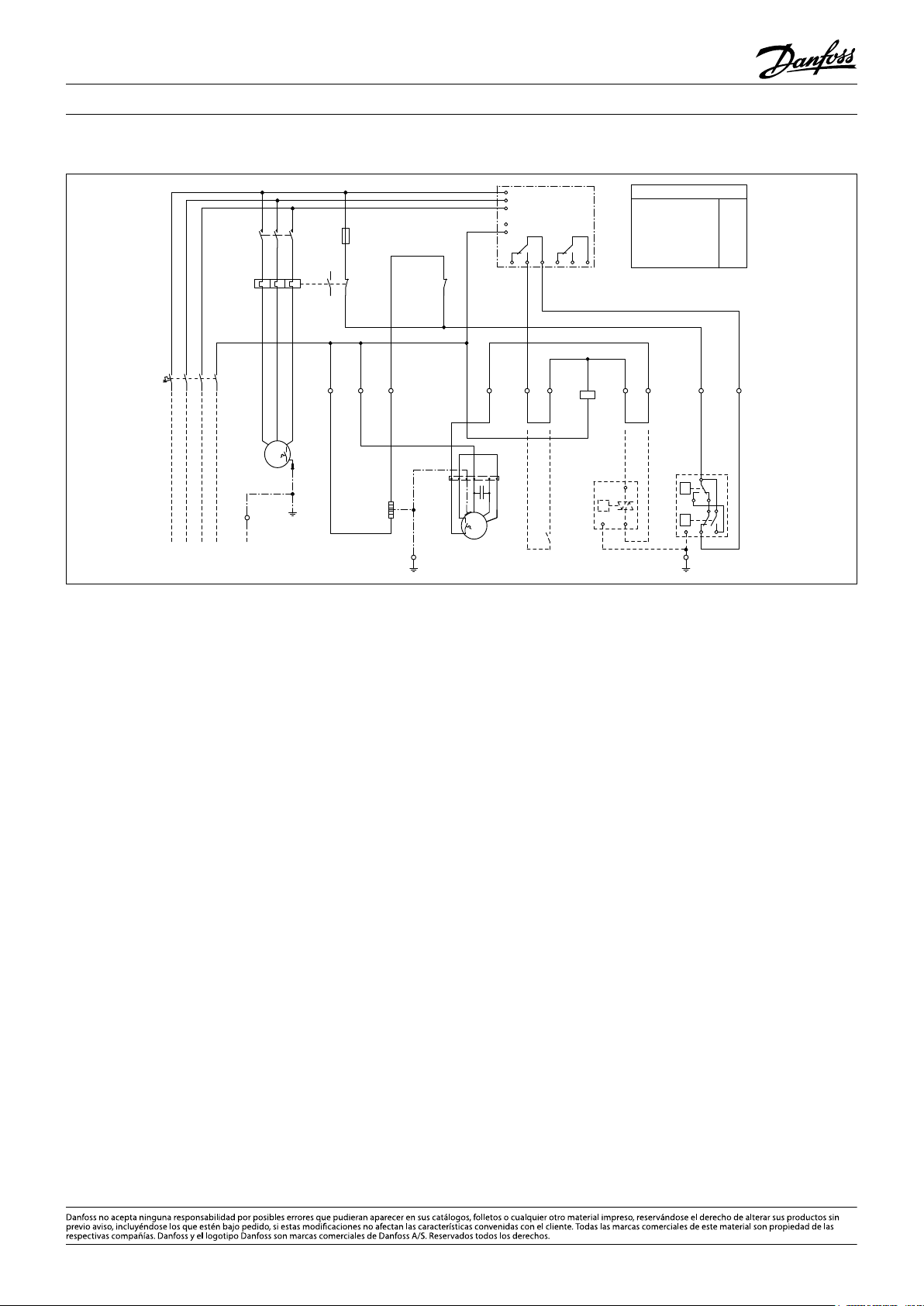
Instrucciones
98
765
4
10
2
3
BN
-S1*
BN
P
12PE
-B1*
BU
BN
PE
-X1
P<
P>
B
C
A
D
PE
-B2
2 4
3
BN
BN
5
6
BN
7
BN
8
-F2
21
22
-K1
A1
A2
-K1
MG73BF
SM500
16 18 15
L1
L2
L3
P
N
26 28 25
-A1
13A
15A
16A
15A
OP-MSUM068MLW05E
OP-MSUM080MLW05E
OP-MSUM099MLW05E
OP-MSUM108MLW05E
OP-LSHM067LLW05E
OP-LSHM084LLW05E
OP-LSHM098LLW05E
12A
15A
15A
BKBUBN
WH
WH
1~
M
GNYE
-M2
3A
1
2
-F3
95
96
97
98
12345
6
-K1
BKGYBN
M
3~
-M1
xxA
56341
2
-F2
BK
BU
BK
BN
1
N2
N1
BNBKGY
BU
PE
-X1
380-400V3N~/50Hz
L1 L2 PEL3 N
1234567
8
-F1
2
1
-E1
PE
-X1
BN
-C3
Código E : OP-LSHM084 - 098, OP-MSUM068 - 080 - 099 - 108
leyenda
BK negro
BU azul
BN marrón
GY gris
RD rojo
WH blanco
FRCC.EI.026.A5.05 - September 2014 Copyright Danfoss Commercial Compressors - DSS - 09/14
A1* Relé de tensión (opcional)
B1* Controlador velocidad del ventilador (opcional)
B2 Presostato de alta & de baja presión
C1 Condensador de funcionamiento (compresor)
C2 Condensador de arranque (compresor)
C3 Condensador de funcionamiento (ventilador)
E1 Resistencia del cárter
F1, F3 Fusible (circuito de control)
F2 Relé de sobrecarga
F4 Compresor protector térmico
M1 Compresor
M2 Motor del ventilador
K1 Contactor
K2 Relé de arranque
R1 Resistencia de absorción
S1* Termostato ambiente (opcional)
X1 Terminales
* Opción (quitar el puente)
Page 28

118UXXXX
INSTRUKTIONEN
OPTYMA™ SLIM PACK OP-LSHM/MSUM/MSHM
L
MADE IN INDIA
A
OP-MSUM034MLW05E
Code no.:
B
Application
C
Refrigerant
D
M.W.P. HP
E
LP (1) 7 bar
Voltage 380-400V3N~/50Hz
F
LRA 30,5 7,5MCC
Serial No.
G
Barcode Serial No:
114X7062
MBP
(1) R404A, R507A
(1) 28 bar
123456CG0514
IP54
(2) R134a
(2) 23 bar
(2) 5 bar
A: Typ
B: Bestellnummer
C: Anwendung, Schutz
D: Kältemittel
E: Zul. Betriebsüberdruck
F: Versorgungsspannung, Stromaufnahme bei
blockiertem Rotor, maximale Stromaufnahme
G: Seriennummer und Barcode
Bild 2
1. Einleitung
Diese Anleitung bezieht sich auf die Verüssigungssätze der Produktreihe Optyma™ Slim Pack OP-LSHM/
MSUM/MSHM (R507A, R404A, R134a, R22) für Kältean
lagen. Sie enthält die erforderlichen Angaben für eine
sichere und ordnungsgemäße Nutzung dieser Produkte.
Der Verüssigungssatz enthält Folgendes:
• Scroll-/Hubkolbenverdichter
• Microchannel-Wärmeübertrager
• Doppeldruckschalter
• Serviceventile Saug/Flüssigkeit
• Robustes, wetterfestes Gehäuse
• Filtertrockner
• Kurbelwannenheizung für Verdichter
• Sammler mit Absperrventil
• Schauglas
• Phasenfolgerelais (Scrollverdichter)
• Vollständig vorverdrahtete Schalttafel (einschließlich Hauptschalter, Verdichterschütz, Überlastrelais)
2. Handhabung und Lagerung
• Es wird empfohlen, die Verpackung erst am endgültigen Montageort zu önen.
• Handhaben Sie das Gerät peglich. Die Verpackung
gestattet den Einsatz eines Gabelstaplers oder -hubwagens. Verwenden Sie ausschließlich geeignete
und sichere Hebezeuge.
• Der Verüssigungssatz darf nur aufrecht stehend
transportiert und gelagert werden.
• Zulässige Lagertemperatur: -35°C bis 50°C.
• Die Verpackung darf weder Regen, noch ätzenden
Atmosphären ausgesetzt werden.
• Vergewissern Sie sich nach dem Auspacken, dass der
Verüssigungssatz vollständig und unbeschädigt ist.
H
I
J
H: Kabeleinführungen
I: Saugleitungsanschluss
J: Flüssigkeitsleitungsanschluss
K: Microchannel-Wärmeübertrager
Bild 3
Befestigungsbolzen (nicht
im Lieferumfang enthalten)
3. Sicherheitsvorkehrungen bei der Installation
Nicht löten, solange die Verüssigereinheit unter
Druck steht.
-
Stellen Sie den Verüssigungssatz niemals in einer
explosionsfähigen Atmosphäre auf.
Achten Sie bei der Positionierung des Verüssi-
gungssatzes darauf, dass keine Durchgänge, Türen,
Fenster oder Ähnliches blockiert werden.
• Achten Sie darauf, dass ausreichend Platz um den Verüssigungssatz gelassen wird, damit die Luft zirkulieren
kann und sich sämtliche Türen önen lassen. Die Min
destabstände zu den Wänden entnehmen Sie Bild1.
• Installieren Sie den Verüssigungssatz NICHT an Orten, die täglich längerer Sonneneinstrahlung ausgesetzt sind.
• Installieren Sie den Verüssigungssatz NICHT in aggressiven oder staubigen Umgebungen.
• Stellen Sie den Verüssigungssatz auf einer horizontalen Fläche (mit weniger als 3Grad Neigung) auf.
Der Boden sollte eine ausreichende Tragfähigkeit
besitzen, um das Gewicht des gesamten Verüssigungssatzes tragen zu können, und stabil genug sein,
um Vibrationen und Interferenzen zu eliminieren.
• Im Aus-Zustand darf die Umgebungstemperatur des
Verüssigungssatzes 50 °C nicht überschreiten.
• Vergewissern Sie sich, dass die Versorgungsspan
nung den Motoreigenschaften des Verüssigungssatzes entspricht (siehe Typenschild).
• Verwenden Sie bei der Installation der Verüssi
gungssätze für HFKW-Kältemittel nur Teile, die speziell für HFKW-Kältemittel vorgesehen sind und die
zuvor nicht in Anlagen mit FCKW- oder HFCKW-Käl
temitteln eingesetzt wurden.
• Verwenden Sie saubere und trockene für Kältemittel
geeignete Kupferrohre und Silberlot.
N
M
K
Bild 1: Mindestmontageabstände
L
[mm]
250 650 550 550
M
[mm]
N
[mm]
Montage und Wartung der
Verüssigungssätze sollten
ausschließlich qualiziertem
Fachpersonal überlassen werden. Befolgen
Sie diese Anleitung sowie die allgemein
anerkannten Regeln für Einbau,
Inbetriebnahme, Wartung und
Instandhaltung von kältetechnischen Anlagen.
Der Verüssigungssatz darf nur für den vorgesehenen Zweck und im entsprechenden Anwendungsbereich eingesetzt werden.
Die Bestimmungen gemäß EN378 (und
alle anderen in Ihrem Land geltenden
Sicherheitsvorschriften) müssen unbedingt
eingehalten werden.
Bei Lieferung ist der Verüssigungssatz mit gasförmigem Sticksto gefüllt, der unter einem Druck
von 1bar steht. In diesem Zustand darf der Verüssigungssatz nicht angeschlossen und betrieben
werden. Näheres hierzu erfahren Sie im Abschnitt
„Montage“.
Der Verüssigungssatz muss in vertikaler Position
montiert gebracht werden (maximale Abweichung
von der Senkrechten: 15 °)
• Benutzen Sie saubere und trockene Anlagenbauteile.
• Die an den Verdichter angeschlossenen Saugleitungen müssen in alle 3 Dimensionen exibel sein, um
Vibrationen zu dämpfen. Darüber hinaus muss die
Verrohrung so erfolgen, dass der Ölrücklauf zum Verdichter sichergestellt ist und dass das Risiko von
sigkeitsschlägen im Verdichter ausgeschlossen ist.
4. Installation
• Die Anlage, in die der Verüssigungssatz eingebaut
wird, muss der Druckgeräterichtlinie (DGRL) Nr.
-
97/23/EG entsprechen. Der Verüssigungssatz selbst
ist kein „Gerät“ im Sinne dieser Richtlinie.
• Die Einheit muss von Beginn an sicher installiert sein
und auf festem Boden stehen. Siehe Abb. 2
• Es wird empfohlen, den Verüssigungssatz auf
Montagegummis oder Schwingungsdämpfern
(nicht im Lieferumfang enthalten) zu montieren.
• Lassen Sie die Sticksto-Füllung langsam durch den
Schraderanschluss ab.
• Schließen Sie den Verüssigungssatz möglichst
schnell an die Anlage an, um eine Kontamination
des Öls mit Umgebungsfeuchtigkeit zu vermeiden.
• Verhindern Sie, dass beim Zuschneiden der Rohrleitungen Fremdkörper in die Anlage eindringen. Bohren Sie niemals Löcher, deren Grate nicht entfernt
-
werden können.
• Lassen Sie beim Löten größte Vorsicht walten. Verwenden Sie nur modernste Lötverfahren und lüften
-
Sie die Rohrleitungen mit gasförmigem Sticksto.
• Schließen Sie die erforderlichen Sicherheits- und
Steuergeräte an. Falls der Schraderanschluss ver-
-
wendet wird, entfernen Sie das interne Ventil.
• Es wird empfohlen, die Saugleitung bis zum Verdichtereintritt mit einer 19mm dicken Isolierung zu dämmen.
O
O
[mm]
Flüs-
28
FRCC.EI.026.A5.03 © Danfoss Commercial Compressors 09/14
Page 29
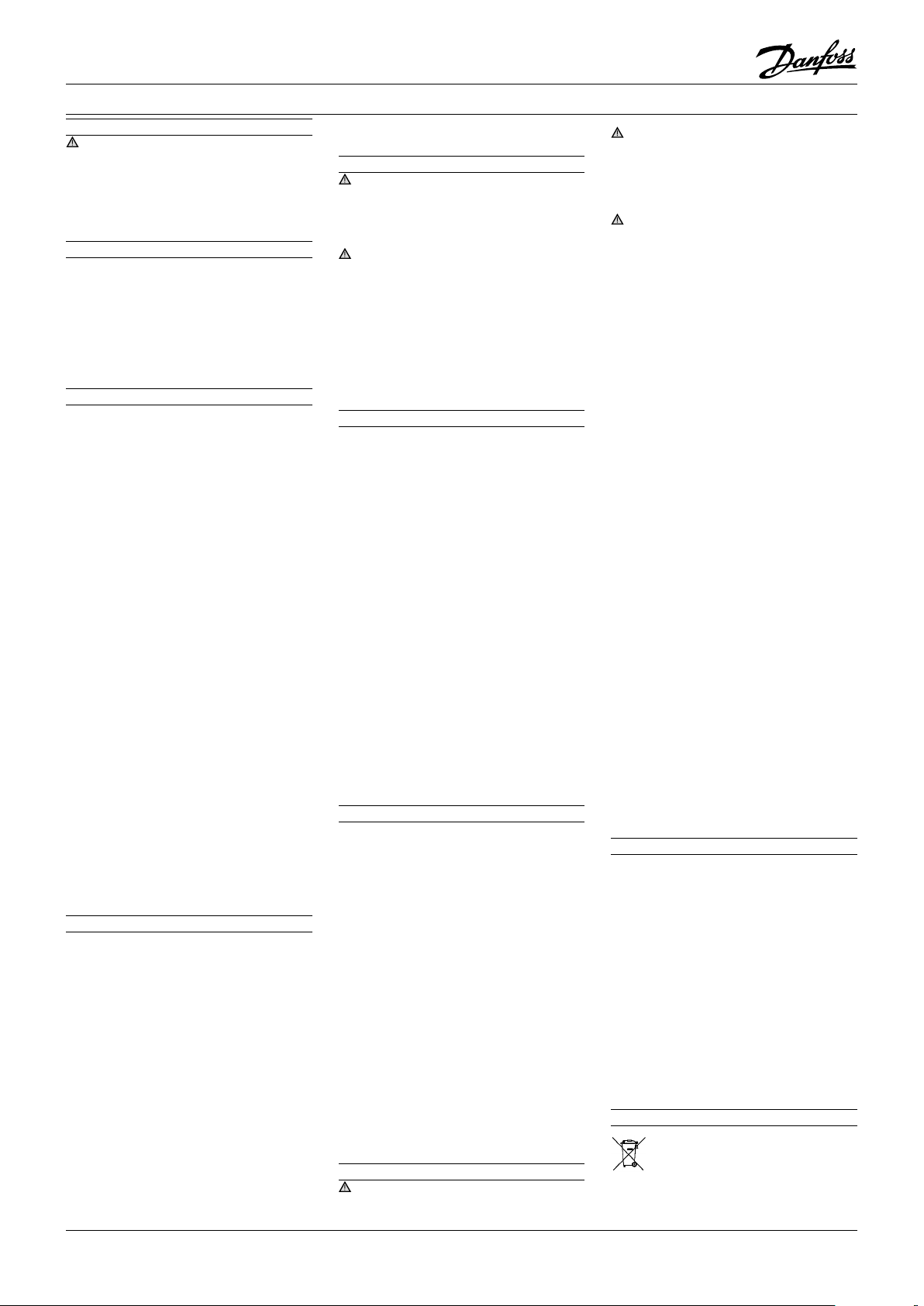
Instruktionen
5. Lecksuche
Setzen Sie den Kreislauf niemals mit Sauersto oder
trockener Luft unter Druck. Das könnte einen Brand
oder eine Explosion verursachen.
• Benutzen Sie für die Lecksuche keinen Farbsto.
• Überprüfen Sie die gesamte Anlage auf Dichtheit.
• Der maximale Prüfdruck beträgt 32 bar.
• Reparieren Sie entdeckte Lecks und wiederholen Sie
dann die Lecksuche.
6. Evakuieren
• Benutzen Sie niemals den Verdichter zur Evakuierung der Anlage.
• Schließen Sie sowohl an die Nieder- als auch an die
Hochdruckseite eine Vakuumpumpe an.
• Evakuieren Sie die Anlage bis auf einen Absolutwert
von 500 µm Hg (0,67 mbar).
• Verwenden Sie während der Evakuierung kein Megohmmeter und legen Sie auch keine Spannung an
den Verdichter an, um eine Beschädigung des Verdichters zu vermeiden.
7. Elektrische Anschlüsse
• Schalten Sie die Spannungsversorgung ab und trennen Sie den Verüssigungssatz vom Netz.
• Stellen Sie sicher, dass die Spannungsversorgung während der Installation nicht eingeschaltet werden kann.
• Die Auswahl aller elektrischen Bauteile muss gemäß
den landesspezischen Normen und Vorschriften für
Verüssigungssätze erfolgen.
• Näheres zu den elektrischen Anschlüssen entnehmen Sie dem Schaltplan.
• Stellen Sie sicher, dass die Versorgungsspannung
den Eigenschaften des Verüssigungssatzes entspricht und stabil anliegt (Nennspannung ±10 %
und Nennfrequenz = ±2,5Hz)
• Dimensionieren Sie die Spannungsversorgungskabel gemäß der für den Verüssigungssatz vorgegebene Spannung und Stromstärke.
• Schützen Sie die Spannungsversorgung und stellen
Sie deren ordnungsgemäße Erdung sicher.
• Die Spannungsversorgung muss den Normen und
gesetzlichen Bestimmungen Ihres Landes entsprechen.
• Die Anlage ist mit Hoch- und Niederdruckschaltern
ausgestattet, die bei Aktivierung die Spannungsversorgung des Verdichters sofort unterbrechen. Parameter für Hoch- und Niederdruckbegrenzungen
müssen durch den Installateur vorgenommen werden, unter Berücksichtigung von Verdichtermodell,
Kältemittel und Anwendungsbereich. Produkte mit
Danfoss MLZ-, LLZ- und NTZ-Verdichtern sind auch
mit Phasenfolgerelais ausgestattet, um das Produkt
gegen Phasenverlust/falsche Phasenfolge/Asymmetrie und Über-/Unterspannung zu schützen.
Bei Anlagen mit einem 3-Phasen-Scrollverdichter (OPSMLZxxxxxxxxE) muss die korrekte Phasensequenz für
die Drehrichtung des Verdichters beachtet werden.
• Ermitteln Sie die Phasensequenz mit einem Phasen
messer, um die Phasenreihenfolge der Leitungsphasen L1, L2 und L3 festzustellen.
• Schließen Sie die Leitungsphasen L1, L2 und L3 an
die entsprechenden Hauptschalterklemmen T1, T2
und T3 an.
8. Füllen der Anlage
• Tragen Sie Schutzkleidung wie z.B. eine Schutzbrille
und Schutzhandschuhe.
• Nehmen Sie den Verdichter niemals unter Vakuum in
Betrieb. Sorgen Sie dafür, dass der Verdichter ausgeschaltet ist und nicht plötzlich auspringt.
• Vor dem Auswechseln des Kältemittels muss sichergestellt sein, dass das Ölniveau im Schauglas des
Verdichters zwischen ¼ und ¾ liegt. Sollte zusätzlich
Öl benötigt werden, entnehmen Sie die nötigen Informationen über das erforderliche Öl bitte dem Tapenschild des Verdichters.
• Verwenden Sie ausschließlich das Kältemittel, auf
das der Verüssigungssatz ausgelegt ist.
• Füllen Sie das üssige Kältemittel in den Verüssiger
oder Sammler. Stellen Sie sicher, dass die Anlage
langsam befüllt wird (auf 4 bis 5 bar bei R404A /
R507A und auf ca. 2bar bei R134a).
• Das Kältemittel darf nicht in die Saugleitung gelangen.
• Dem Öl/Kältemittel dürfen keine Zusätze beigemischt werden.
• Die Anlage wird dann weiter befüllt, bis die Installation
beim Betrieb einen stabilen Nennzustand erreicht hat.
• Lassen Sie den Einfüllstutzen niemals an den Kreislauf angeschlossen.
9. Abschließende Prüfung vor der Inbetriebnahme
Verwenden Sie gemäß den allgemeinen und lan-
desspezischen Sicherheitsnormen und -vorschriften
Sicherheitsvorrichtungen wie Sicherheitsdruckschalter
und mechanische Überdruckventile. Vergewissern Sie
sich, dass diese Sicherheitsvorrichtungen funktionstüchtig und ordnungsgemäß eingestellt sind.
Überprüfen Sie, dass die Einstellungen für die Hoch-
druckschalter und Überdruckventile den maximalen
Betriebsdruck jeglicher Bauteile der Anlage nicht überschreiten.
• Vergewissern Sie sich, dass sämtliche elektrischen
Anschlüsse ordnungsgemäß befestigt sind und den
Vorschriften Ihres Landes entsprechen.
• Wenn eine Kurbelwannenheizung erforderlich ist,
muss diese mindestens 12 Stunden vor der ersten
Inbetriebnahme der Anlage eingeschaltet werden.
Dies gilt auch vor einer erneuten Inbetriebnahme
nach einer längeren Stillstandszeit.
10. Inbetriebnahme
• ttel betrieben werden.
• Alle Serviceventile müssen geönet sein. Siehe Abb. 3.
• Überprüfen Sie, ob die vorhandene Versorgungsspannung mit dem erforderlichen Wert für den Verüssigungssatz übereinstimmt.
• Überprüfen Sie, ob die Kurbelwannenheizung funk
tioniert.
• Überprüfen Sie, ob sich der Lüfter frei drehen kann.
• Überprüfen Sie, ob die Schutzfolie auf der Rückseite
des Verüssigers entfernt wurde.
• Nehmen Sie einen Ausgleich zwischen Hoch- und
Niederdruckseite vor.
• Schalten Sie den Verüssigungssatz ein. Der Verüs
sigungssatz muss sofort anlaufen. Falls der Verdichter nicht anläuft, überprüfen Sie die Verdrahtung
und die Spannung an den Klemmen.
• Ob sich ein 3-Phasen-Verdichter in die Gegenrich
tung dreht, lässt sich an folgenden Phänomenen erkennen: Der Verdichter baut keinen Druck auf. Der
Verdichter arbeitet mit einem ungewöhnlichen ho
hen Geräuschpegel. Die Leistungsaufnahme des Verdichters ist ungewöhnlich gering. Bei falscher Drehrichtung des Verdichters muss der Verdichter sofort
abgeschaltet werden, um die Leitungsphasen an die
korrekten Klemmen anzuschließen.
• Bei korrekter Drehrichtung ist an der Niederdruckan
zeige bzw. am Niederdruckmanometer ein sinkender Druck abzulesen – und an der Hochdruckanzeige bzw. am Hochdruckmanometer ein steigender
Druck.
11. Überprüfung bei laufendem Verflüssigungssatz
• Überprüfen Sie die Drehrichtung des Lüfters. Die
-
Luft muss vom Verüssiger zum Lüfter strömen.
• Überprüfen Sie Stromaufnahme und Spannung.
• Überprüfen Sie die Überhitzung der Saugleitung, um
das Risiko von Flüssigkeitsschlägen zu vermindern.
• Sofern ein Schauglas vorhanden ist, beobachten Sie
den Ölstand beim Anlaufen und während des Betriebs, um sicherzustellen, dass der Ölstand sichtbar
bleibt.
• Beachten Sie die Betriebsgrenzen.
• Überprüfen Sie alle Leitungen auf übermäßige Vibrationen. Bewegungen von mehr als 1,5 mm erfordern
Korrekturmaßnahmen wie z.B. die Verwendung von
Rohrhalterungen.
• Ggf. kann auf der Niederdruckseite in größtmöglichem Abstand zum Verdichter üssiges Kältemittel
nachgefüllt werden. Während dieses Nachfüllvorgangs muss der Verdichter in Betrieb sein.
• Über füllen Sie die Anlage nicht.
• Lassen Sie niemals Kältemittel in die Atmosphäre
entweichen.
• Führen Sie eine allgemeine Inspektion der Installation hinsichtlich Sauberkeit, Geräuschpegel und Lecks
durch, bevor Sie den Installationsort verlassen.
• Dokumentieren Sie die Art und Menge des Kältemittels sowie die Betriebsbedingungen als Referenz für
künftige Inspektionen.
12. Wartung
Schalten Sie den Verüssigungssatz immer mit dem
Hauptschalter aus, bevor Sie die Lüftertür önen.
Der in der Anlage herrschende Druck und die Oberächentemperatur können dauerhafte körperliche
Schäden verursachen.
Die Bediener, Installateure und Wartungstechniker
müssen dementsprechend geschult und ausgerüstet
sein. Die Temperatur der Rohrleitungen kann 100 °C
überschreiten und schwere Verbrennungen verursachen.
Stellen Sie sicher, dass regelmäßig Serviceinspektionen gemäß den Vorschriften Ihres Landes durchgeführt werden, um einen zuverlässigen Betrieb der Anlage zu gewährleisten.
Um systembedingte Probleme zu vermeiden, werden
die folgenden regelmäßigen Wartungsarbeiten empfohlen:
• Vergewissern Sie sich, dass die Sicherheitsvorrich-
tungen funktionstüchtig und ordnungsgemäß eingestellt sind.
• Stellen Sie sicher, dass keine Lecks in der Anlage vor-
handen sind.
• Überprüfen Sie die Stromaufnahme des Verdichters.
• Vergewissern Sie sich anhand der Wartungsunterla-
gen, dass die Anlage entsprechend den bisherigen
Werten und Betriebsbedingungen läuft.
• Überprüfen Sie, ob sämtliche elektrischen Anschlüs-
se noch ordnungsgemäß befestigt sind.
• Sorgen Sie dafür, dass der Verüssigungssatz sauber
ist und bleibt, und vergewissern Sie sich, dass die Bauteile des Verüssigungssatzes, die Rohre und die
trischen Anschlüsse frei von Rost und Oxidation sind
Der Verüssiger muss mindestens einmal im Jahr auf
Verschmutzungen überprüft und ggf. gereinigt wer
den. Ins Innere des Verüssigers gelangen Sie über die
Lüftertür. Bei Microchannel-Wärmeübertragern lagert
sich der Schmutz eher auf als im Verüssiger. Deshalb
sind sie leichter zur reinigen als Kupferrohr-Lamellen
verüssiger.
-
• Schalten Sie den Verüssigungssatz mit dem Haupt-
schalter aus, bevor Sie ein Panel der Einheit entfernen.
• Entfernen Sie oberächlichen Schmutz, Blätter, Fa-
sern usw. mit einem Staubsauger mit Bürstenaufsatz
-
bzw. mit einem anderen weichen Aufsatz. Alternativ
hierzu können Sie auch Druckluft von innen nach
außen durch das Register blasen und mit einer wei-
-
chen Bürste abbürsten. Verwenden Sie keine Drahtbürste. Stoßen Sie nicht mit dem Rohr oder der Düse
des Staubsaugers gegen die Spule und vermeiden
Sie Kratzer.
Falls der Kältemittelkreislauf geönet wurde, muss die
Anlage mit trockener Luft oder Sticksto „gespült“ wer-
den, um jegliche Feuchtigkeit zu entfernen. Zudem
muss ein neuer Filtertrockner
eingebaut werden. Falls eine Evakuierung des Kältemittels erforderlich sein sollte, muss diese so vorgenommen werden, dass kein Kältemittel in die Umwelt
entweicht.
13. Garantie
Zur Geltendmachung eines Garantieanspruchs müssen
stets die Typenbezeichnungen- und Seriennummer
des Produkts übermittelt werden.
Unter Umständen erlischt die Produktgarantie in folgenden Fällen:
• Fehlen des Typenschilds.
• Äußere Modikationen, vor allem durch Bohren,
Schweißen, gebrochene Füße und Stoßspuren.
• Önung des Verdichters/Rückgabe eines unversie-
gelten Verdichters.
• Rost, Wasser oder Farbsto zur Lecksuche im Inneren
des Verdichters.
• Verwendung eines von Danfoss nicht zugelassenen
Kältemittels oder Schmierstoes.
• Jegliche Abweichung von den Hinweisen zur Instal-
lation, Anwendung oder Wartung.
• Benutzung in mobilen Anwendungen.
• Benutzung in einer explosionsfähigen Atmosphäre.
• Keine Angabe der Modell- oder Seriennummer bei
der Geltendmachung des Garantieanspruchs.
14. Entsorgung
Danfoss empehlt die Entsorgung der Ver-
üssigungssätze und des Öls durch ein entsprechend qualiziertes Unternehmen am
Standort der Anlage.
elek-
.
-
-
29FRCC.EI.026.A5.03 © Danfoss Commercial Compressors 09/14
Page 30

Instruktionen
98
765
4
10
2 3
98
765
4
10
2 3
Code G: OP-MSHM010- 012 - 015, OP-LSHM015 - 018
1
-F3
3A
2
95
97
98
96
.
.
N2
N1
BU
BK
-F1
12345
-K1
-F2
xxA
-K2
BU
BN
6
56341
2
BU
BN
10
11
14
12
13
13
-C1
-A1*
L1
SM500
L2
L3
MG73BF
P
21
-K1
22
.
1
BK BN
16 18 15
.
2
BK
N
26 28 25
BN
BN
.
A1
-K1
4.3
A2
BN
OP-MSHM010SCW05G
OP-MSHM012SCW05G
OP-MSHM015SCW05G
OP-LSHM015SCW05G
OP-LSHM018SCW05G
.
5.6
-F2
5,3A
6,3A
6,8A
5,5A
5,8A
BN
BN
.
.
7
8
BU
BN
.
-X1
L PEN
230V1N~/50Hz
-M1
PE
S C R
M
1~
PE
-E1
-C3
BUBNBN
1
2
-M2
1~
M
-X1
.
PE
Code G: OP-LSHM026 - 034 - 048 - 068 - 074, OP-MSHM018 - 024 - 026 - 034
-A1*
12345
-K1
-F2
xxA
BU
BN
-F1
-K2
6
56341
2
BN
BU
5
5
2
-R1
44
1
-C1
-C2
OP-.......AJW05G
-F4
BLBKBR
L PEN
-X1
SCR
M
-M1
PE
1~
PE
OP-......SCW05G
OP-......FHW05G
230V1N~/50Hz
1
-F3
3A
2
95
97
98
96
N2 5 6
N1
BU
BK
BK BN
-K1
1
21
22
-C3
BUBNBN
1
-E1
2
-M2
M
1~
-X1
-S1*
L1
L2
L3
P
N
16 18 15
2 43
BK
PE
-B1*
BN
P
SM500
MG73BF
26 28 25
BN
-S1*
12PE
-K1
A1
A2
-B1*
-B2
A
P<
B
P>
D
C
PE
.
-X1
PE
OP-MSHM024AJW05G 10A
OP-MSHM026AJW05G
OP-MSHM034AJW05G
OP-LSHM026AJW05G
OP-LSHM034AJW05G
OP-LSHM048NTW05G
OP-LSHM068NTW05G
OP-LSHM074FHW05G
BN
P
12PE
-F2
-X1
-B2
P<
P>
6,7AOP-MSHM018SCW05G
13A
15A
7,9A
10A
11A
17A
24A
BN
BN
7
8
BU
BN
A
B
D
C
PE
PE
Legende
BK schwarz
BU blau
BN braun
GY grey
RD rot
WH weiss
A1* Spannungsrelais (optional)
B1* Lüfterdrehzahlregler (optional)
B2 Hochdruckschalter & Niederdruckschalter
C1 Betriebskondensator (Verdichter)
C2 Anlaufkondensator (Verdichter)
C3 Betriebskondensator (Lufter)
E1 Kurbelwannenheizung
F1, F3 Sicherung (Steuerkreis)
F2 Überlastrelais
F4 Kompressor Wicklungsschutz
M1 Verdichter
M2 Lüftermotor
K1 Schütz
K2 Anlaufrelais
R1 Löschwiderstand
S1* Room thermostat (option)
X1 Reihenklemmen
* Option (Brücke entfernen)
30 FRCC.EI.026.A5.03 © Danfoss Commercial Compressors 09/14
Page 31

Instruktionen
98
765
4
10
2 3
98
765
4
10
2
3
2 4
3
BN
BN
BN
A1
A2
-K1
MG73BF
SM500
16 18 15
L1
L2
L3
P
N
26 28 25
-A1
-S1*
21
22
-K1
5 6
BN
P
12PE
-B1*
BN
7
BU
BN
BN
8
P<
P>
B
C
A
D
PE
-B2
PE
-X1
-F2
OP-MSUM068MLW05G
OP-MSUM080MLW05G
32A
38A
BKBUBN
WH
WH
1~
M
GNYE
-M2
BK BN
1
BK
N1
N2
3A
1
2
-F3
95
96
97
98
BK
BN
-C1
-R1
GY
M
1~
SCR
PE
-M1
12345
6
-K1
xxA
56341
2
-F2
BU
BN
BN
-F1
BU
PE
-X1
230V1N~/50Hz
L PEN
S
-X1
BU
PE
-X1
2
1
-E1
BN
-C3
Code G: OP-MSUM034 - 046 - 057
12345
-K1
-F2
xxA
2
BN
BU
BN
-F1
-X1
L PEN
230V1N~/50Hz
-C1
-R1
-M1
PE
6
56341
BU
BK
BN
S C R
M
1~
-A1
L1
SM500
2 4
BK
M
PE
L2
L3
P
N
16 18 15
BN
3
MG73BF
26 28 25
-K1
BN
-S1*
A1
A2
-B1*
5 6
BN
P
12PE
1
-F3
3A
2
95
97
98
96
N1
N2
BK
BU
GY
21
-K1
22
1
BK BN
-C3
PE
-E1
BUBNBN
1
-M2
2
1~
-X1
-F2
OP-MSUM034MLW05G
OP-MSUM046MLW05G
OP-MSUM057MLW05G
BN
BN
-B2
A
P<
B
P>
PE
-X1
PE
19A
25A
26A
BN
7
8
BU
D
C
Code G: OP-MSUM068 - 080
Legende
BK schwarz
BU blau
BN braun
GY grey
RD rot
WH weiss
A1* Spannungsrelais (optional)
B1* Lüfterdrehzahlregler (optional)
B2 Hochdruckschalter & Niederdruckschalter
C1 Betriebskondensator (Verdichter)
C2 Anlaufkondensator (Verdichter)
C3 Betriebskondensator (Lufter)
E1 Kurbelwannenheizung
F1, F3 Sicherung (Steuerkreis)
F2 Überlastrelais
F4 Kompressor Wicklungsschutz
M1 Verdichter
M2 Lüftermotor
K1 Schütz
K2 Anlaufrelais
R1 Löschwiderstand
S1* Room thermostat (option)
X1 Reihenklemmen
* Option (Brücke entfernen)
31FRCC.EI.026.A5.03 © Danfoss Commercial Compressors 09/14
Page 32

Instruktionen
98
765
4
10
2 3
43
BN
BN
BN
A1
A2
-K1
BK
2
BKBUBN
WH
WH
1~
M
GNYE
-M2
21
22
-K1
95
96
97
98
3A
1
2
-F3
BK BN
1
BKN1BU
N2
MG73BF
SM500
16 18 15
L1
L2
L3
P
N
26 28 25
-A1
PE
-X1
2
1
-E1
-C3
12345
6
-K1
xxA
56341
2
-F2
BU
BN
BKBNBU
-C2
M
1~
SCR
PE
-M1
-R1
-C1
-R2
5
2
1
5
-K2
-S1*
BN
-F1
BU
230V1N~/50Hz
L PEN
PE
-X1
5 6
BN
P
21PE
-B1
BN
7
BU
BN
BN
8
PE
-X1
P<
P>
B
C
A
D
PE
-B2
-F2
40AOP-MSUM093MLW06G
98
765
4
10
2 3
Code G: OP-MSUM093
Code E: OP-LSHM048-068 - 074, OP-MSHM026 - 034, OP-MSUM034 - 046 - 057
-A1*
L1
L2
BUBNBN
M
1~
-X1
L3
P
N
16 18 15
2 43
BK
PE
12345
-K1
-F2
xxA
BNBKGY
1234567
-F1
BU
8
-M1
L1 L2 PEL3 N
-X1
380-400V3N~/50Hz
PE
6
56341
2
BKGYBN
M
3~
-F3
3A
1
2
95
97
98
96
BU
BK
-E1
21
-K1
22
BN
1N2N1 5 6
BK
-C3
1
-M2
2
SM500
MG73BF
26 28 25
BN
BN
-S1*
-K1
-A1* -F2
--OP-MSHM026AJW05E
X
X
X
-
-
-
A1
A2
BN
-B1*
P
OP-MSHM034AJW05E
OP-MSUM034MLW05E
OP-MSUM046MLW05E
OP-MSUM057MLW05E
OP-LSHM048NTW05E
OP-LSHM068NTW05E
OP-LSHM074FHW05E 7,9A
-B2
A
P<
B
-X1
P>
PE
PE
12PE
4,0A
4,8A
7,0A
9,5A
10A
4,8A
8,4A
BN
BN
7
8
BU
BN
D
C
Legende
BK schwarz
BU blau
BN braun
GY grey
RD rot
WH weiss
32 FRCC.EI.026.A5.03 © Danfoss Commercial Compressors 09/14
A1* Spannungsrelais (optional)
B1* Lüfterdrehzahlregler (optional)
B2 Hochdruckschalter & Niederdruckschalter
C1 Betriebskondensator (Verdichter)
C2 Anlaufkondensator (Verdichter)
C3 Betriebskondensator (Lufter)
E1 Kurbelwannenheizung
F1, F3 Sicherung (Steuerkreis)
F2 Überlastrelais
F4 Kompressor Wicklungsschutz
M1 Verdichter
M2 Lüftermotor
K1 Schütz
K2 Anlaufrelais
R1 Löschwiderstand
S1* Room thermostat (option)
X1 Reihenklemmen
* Option (Brücke entfernen)
Page 33

Instruktionen
98
765
4
10
2
3
BN
-S1*
BN
P
12PE
-B1*
BU
BN
PE
-X1
P<
P>
B
C
A
D
PE
-B2
2 4
3
BN
BN
5
6
BN
7
BN
8
-F2
21
22
-K1
A1
A2
-K1
MG73BF
SM500
16 18 15
L1
L2
L3
P
N
26 28 25
-A1
13A
15A
16A
15A
OP-MSUM068MLW05E
OP-MSUM080MLW05E
OP-MSUM099MLW05E
OP-MSUM108MLW05E
OP-LSHM067LLW05E
OP-LSHM084LLW05E
OP-LSHM098LLW05E
12A
15A
15A
BKBUBN
WH
WH
1~
M
GNYE
-M2
3A
1
2
-F3
95
96
97
98
12345
6
-K1
BKGYBN
M
3~
-M1
xxA
56341
2
-F2
BK
BU
BK
BN
1
N2
N1
BNBKGY
BU
PE
-X1
380-400V3N~/50Hz
L1 L2 PEL3 N
1234567
8
-F1
2
1
-E1
PE
-X1
BN
-C3
Code E: OP-LSHM084 - 098, OP-MSUM068 - 080 - 099 - 108
Legende
BK schwarz
BU blau
BN braun
GY grey
RD rot
WH weiss
FRCC.EI.026.A5.03 - September 2014 Copyright Danfoss Commercial Compressors - DSS - 09/14
A1* Spannungsrelais (optional)
B1* Lüfterdrehzahlregler (optional)
B2 Hochdruckschalter & Niederdruckschalter
C1 Betriebskondensator (Verdichter)
C2 Anlaufkondensator (Verdichter)
C3 Betriebskondensator (Lufter)
E1 Kurbelwannenheizung
F1, F3 Sicherung (Steuerkreis)
F2 Überlastrelais
F4 Kompressor Wicklungsschutz
M1 Verdichter
M2 Lüftermotor
K1 Schütz
K2 Anlaufrelais
R1 Löschwiderstand
S1* Room thermostat (option)
X1 Reihenklemmen
* Option (Brücke entfernen)
Page 34

118UXXXX
VEJLEDNING
OPTYMA™ SLIM PACK OP-LSHM/MSUM/MSHM
L
MADE IN INDIA
A
OP-MSUM034MLW05E
Code no.:
B
Application
C
Refrigerant
D
M.W.P. HP
E
LP (1) 7 bar
Voltage 380-400V3N~/50Hz
F
LRA 30,5 7,5MCC
Serial No.
G
Barcode Serial No:
114X7062
MBP
(1) R404A, R507A
(1) 28 bar
123456CG0514
IP54
(2) R134a
(2) 23 bar
(2) 5 bar
A: Model
B: Bestillingsnummer
C: Applikation, Beskyttelse
D: Kølemiddel
E
: Arbejdstrykområde i huset
F: Forsyningsspænding, LRA
(Locked Rotor Ampere), MCC
(Maximum Current Consumption)
G: Serienummer og stregkode
Billede2
1 – Introduktion
Denne vejledning omhandler Optyma TM Slim Packkondenseringsaggregaterne OP-LSHM/MSUM/
MSHM (R507A, R404A, R134a, R22), der bruges
til køleanlæg. Vejledningen indeholder oplysninger om sikkerhed og korrekt anvendelse af
produktet.
Kondenseringsaggregatet indeholder følgende:
•
Scroll-/stempelkompressor
• mikrokanal-kondensator
• dobbelte dierentrykspressostater
• serviceventiler, suge/væskeledninger
• robust, vejrbestandigt hus
• tørrelter
• krumtaphusvarmelegeme til kompressor
• receiver med stopventil
• skueglas.
•
Fasesekvensrelæ (
Scrollkompressor)
• Fuldt fortrådet elektrisk panel (herunder
hovedkontakt, kompressorkontaktor,
overbelastningsrelæ)
2 – Håndtering og opbevaring
• Det anbefales ikke at åbne emballagen, før aggregatet
er fremme ved dets endelige installationssted.
• Vær forsigtig ved håndtering af aggregatet.
ballagen muliggør anvendelse af gaeltruck
pallevogn. Anvend egnet og sikkert løftegrej.
• Kondenseringsaggregatet skal opbevares og
transporteres i opret stilling.
• Kondenseringsaggregatet skal opbevares ved
mellem -35°C og 50°C.
• Kondenseringsaggregatet og emballagen må ikke
Em-
eller
K
H
I
J
H: Kabelindføringer
I: Sugerør
J: Væskerør
K: Microkanal-kondensator
Billede3
Montagebolte (medfølger ikke)
udsættes for regn eller korroderende atmosfærer.
• Efter udpakningen skal du kontrollere, at aggregatet er helt og ubeskadiget.
3 – Forholdsregler ved installationen
Undlad lodning, så længe kondenseringsaggre-
gatet er under tryk.
Aggregatet må aldrig anvendes i en brandbar
atmosfære.
Placér aggregatet, så det ikke blokerer trakveje,
døre, vinduer o.l.
• Sørg for, at der er tilstrækkelig plads omkring aggregatet,
til at luften kan cirkulere og døre kan
Se billede1 for minimumsafstanden til vægge.
• Installér ikke aggregatet på steder, der dagligt
udsættes for sollys i længere tidsrum.
• Installér ikke aggregatet i aggressive og støvede
omgivelser.
• Installér aggregatet på et underlag med en vandret overade (< 3° hældning), som er stærkt og
stabilt nok til at bære aggregatets samlede vægt
og eliminere vibration og forstyrrelser.
• Aggregatets omgivelsestemperatur må ikke overstige 50°C, når det er slukket.
• Kontrollér, at strømforsyningen svarer til kondenseringsaggregatets specikationer (se typeskiltet).
• Når aggregater til HFC-kølemidler monteres, skal
der anvendes udstyr, som er forbeholdt HFC-kø
lemidler, og som aldrig har været anvendt til CFCeller HCFC-kølemidler.
• Anvend rene og tørre kølemiddelegnede kob
berrør og slagloddemateriale med sølvlegering.
• Anvend rene og tørre anlægsdele.
åbnes.
N
M
Billede1: Mindste monteringsafstande
L
[mm]
250 650 550 550
M
[mm]
N
[mm]
Kondenseringsaggregatet må kun
monteres og serviceres af uddannet
personale. Følg denne vejledning og almindelig
køleteknisk praksis i forbindelse med montering,
idriftsættelse, vedligeholdelse og servicering.
Kondenseringsaggregatet må kun anvendes
til det/de formål, det er beregnet til, og inden
for dets anvendelsesområde.
EN 378 (og andre gældende sikkerhedsbestemmelser) skal altid overholdes.
Kondenseringsaggregatet leveres med et
nitrogengastryk (1 bar) og kan derfor ikke
umiddelbart tilsluttes. Se afsnittet «Montering» for yderligere oplysninger.
Kondenseringsaggregatet skal stå opret og
håndteres med forsigtighed (maks. hældningsvinkel fra vertikal: 15°).
• Sugeledningen, som er forbundet med kompressoren, skal være eksibel i tre dimensioner for at
kunne dæmpe vibrationerne. Derudover skal rør
føringen sikre olieretur til kompressoren og eliminere væskeslag i kompressoren.
4 – Installation
• Den installation, som kondenseringsaggregatet monteres
i, skal være i overensstemmelse med Trykudstyrsdirektivet (PED) nr. 97/23/EF. Kondenseringsaggregatet er ikke i sig selv omfattet af direktivet.
• Aggregatet skal være sikkert monteret i et stabilt
og fast ophæng og fastgjort fra starten. Se billede2.
• Det anbefales at montere aggregatet på gummi-
fødder eller vibrationsdæmpere (medfølger ikke).
• Tøm langsomt nitrogenfyldningen ud gennem
schrader-porten.
• Slut aggregatet til anlægget så hurtigt som muligt
for at undgå oliekontaminering fra fugtighed i
omgivelserne.
• Sørg for, at der ikke kommer spåner eller lignende
ind i anlægget, når der skæres rør. Bor aldrig huller,
hvis graterne ikke kan ernes.
• Vær meget forsigtig ved slaglodning. Anvend altid
de sidste nye teknikker, og udluft rørene med en
nitrogengasgennemstrømning.
• Tilslut de nødvendige sikkerheds- og styreanordninger. Når schrader-porten anvendes til dette
formål, skal den indvendige ventil ernes.
-
• Det anbefales at isolere sugerøret til kompressorens sugeside med 19mm tyk isolering.
-
O
O
[mm]
-
FRCC.EI.026.A5.01 © Danfoss Commercial Compressors 09/1434
Page 35

Instruktion
5 – Lækregistrering
Kredsløbet må aldrig tryksættes med oxygen eller
tør luft. Dette kan medføre brand eller eksplosion.
• Anvend ikke farvestoer til lækregistrering.
• Udfør en læksøgningstest på hele anlægget.
• Det maksimale testtryk er 32bar.
• Hvis der opdages en læk, skal denne repareres,
og læksøgningen skal gentages.
6 – Vakuumtørring
• Kompressoren må aldrig anvendes til tomsugning
af anlægget.
• Slut en vakuumpumpe til både lavtryks- og højtrykssiden.
• Vakuumer anlægget til et absolut tryk på 500μm
Hg (0,67mbar).
• Der må hverken anvendes et megohmmeter eller
sluttes strøm til kompressoren, mens den er under
vakuum, da dette kan forårsage indvendige skader.
7 – Elektriske tilslutninger
• Sluk og isoler hovedstrømforsyningen.
• Kontrollér, at strømforsyningen ikke kan tilsluttes
under montagen.
• Alle elektriske komponenter skal vælges i overensstemmelse med lokale standarder og kondenseringsaggregatets krav.
• Se eldiagrammet for oplysninger om elektrisk tilslutning.
• Kontrollér, at forsyningsspændingen svarer til aggregatets specikationer, og at forsyningsspændingen er stabil (mærkespænding ±10%, mærkefrekvens ±2,5Hz)
• Dimensionér forsyningskablerne efter aggregatets
data for spænding og strøm.
• Beskyt strømforsyningen, og kontrollér, at den er
korrekt jordet..
• Strømforsyningen skal etableres i overensstemmelse
med lokale standarder og lovkrav.
• Aggregatet har høj- og lavtrykspressostater, der
straks afbryder strømforsyningen til kompressoren, hvis de udløses. Parametre for afbrydelse
ved højt og lavt tryk skal indstilles af installatøren under hensyntagen til kompressormodel,
kølemiddel og anvendelse. Aggregater med
Danfoss MLZ-, LLZ- og NTZ-kom
udstyret med et fasesekvensrelæ
pressorer er også
for at beskytte
aggregatet mod fasetab/-sekvens/-asymmetri
og under-/overspænding.
For aggregater med en trefaset scrollkompressor
skal det kontrolleres, at fasesekvensen for kompressorens rotationsretning er korrekt.
• Påvis fasesekvensen ved hjælp af et fasemeter,
som fastslår rækkefølgen for linjefase L1, L2 og L3.
• Slut linjefaserne L1, L2 and L3 til henholdsvis
klemme T1, T2 og T3.
8 – Fyldning af anlægget
• Anvend personlige værnemidler som beskyttelsesbriller og -handsker.
• Start aldrig kompressoren under vakuum. Kompressoren skal være slukket.
• Inden påfyldning af kølemiddel sk al det kontrolleres,
at oliestanden er mellem 1/4 og 3/4 på kompressorens olieskueglas. Se kompressorens typeskilt
for den korrekte olietype, hvis yderligere oliepåfyldning er nødvendig.
• Anvend kun det kølemiddel, som aggregatet er
beregnet til.
• Fyld kølemiddel i væskefase i kondensatoren eller
receiveren. Påfyld kølemidlet langsomt indtil 4-5bar
for R404A/R507A eller R22 og ca. 2bar for R134a.
• Undgå at sende kølemiddelvæske gennem sugeledningen.
• Additiver må ikke iblandes olien og/eller kølemidlet.
• Den resterende påfyldning udføres, indtil installationen har nået en stabilt nominel tilstand under drift.
• Efterlad aldrig fyldningscylinderen sluttet til
kredsløbet.
9 – Godkendelse inden idriftsættelse
Anvend sikkerhedsanordninger, som f.eks. sikkerhedspressostater og mekaniske sikkerhedsventiler
som både overholder generelle og lokale bestemmelser og sikkerhedsstandarder. Sørg for, at de fungerer og er indstillet korrekt.
Kontrollér, at indstillingerne på højtrykspressostaterne og sikkerhedsventilerne ikke overstiger det
maksimale driftstryk på nogen af anlæggets dele.
• Kontrollér, at alle elektriske tilslutninger er korrekt
fastgjorte og overholder de lokale bestemmelser.
•
Når der anvendes et krumtaphusvarmelegeme,
skal det strømføres mindst 12 timer før den
første opstart og før opstart efter langvarige
standsninger.
10 – Opstart
• Start aldrig aggregatet, hvis der ikke er påfyldt
kølemiddel.
• Alle serviceventiler skal være åbne. Se billede3.
• Kontrollér, at der overensstemmelse mellem ag-
gregatet og forsyningsspændingen.
• Kontrollér, at krumtaphusvarmelegemet fungerer.
• Kontrollér, at blæseren kan rotere frit.
• Kontrollér, at beskyttelsespladen bag på konden-
satoren er ernet.
• Afbalancer højtrykket/lavtrykket.
• Slut strøm til kompressoren. Den skal starte med
det samme. Hvis kompressoren ikke starter, skal
ledningsføringen, klemmernes spænding og fasesekvensen kontrolleres.
• Eventuel omvendt rotation af en trefaset kom-
pressor kan påvises ved følgende driftsmønster:
Aggregatet starter ikke, kompressoren opbygger
ikke tryk, dens lydniveau er unormalt højt, og
strømforbruget er unormalt lavt. I dette tilfælde
skal aggregatet slukkes med det samme, og faserne sluttes til de korrekte klemmer.
• Hvis rotationsretningen er korrekt, skal lavtryks-
visningen på lavtryksmanometeret angive et faldende tryk, og højtryksvisningen på højtryksmanometeret skal angive et stigende tryk.
11 – Kontrol med kørende aggregat
• Kontrollér blæserens rotationsretning. Der skal
strømme luft fra kondensatoren mod blæseren.
• Kontrollér strømforbrug og spænding.
• Kontrollér sugeoverhedningen for at reducere ri-
sikoen for væskeslag.
• Hvis et olieskueglas er monteret, skal det ved
start og under driften kontrolleres, at oliestanden
forbliver synlig.
• Overhold driftsgrænserne.
• Kontrollér alle rør for unormale vibrationer. Hvis
der er bevægelser på mere end 1,5mm, skal der
træes korrigerende foranstaltninger, som f.eks.
montering af rørstøtter.
• Hvis det er nødvendigt, kan der tilføjes et ekstra
kølemiddel i væskefase i lavtrykssiden så langt
væk som muligt fra kompressoren. Kompressoren skal køre under denne proces.
• Anlægget må ikke overfyldes.
• Slip aldrig kølemiddel ud i atmosfæren.
• Inden monteringsstedet forlades, udføres et ge-
nerelt monteringseftersyn, hvor renlighed, støj
og tæthed kontrolleres.
• Notér både kølemiddeltypen og -fyldningen for-
uden driftsbetingelserne. Dette anvendes som
referencepunkt ved fremtidige eftersyn.
12 – Vedligeholdelse
Afbryd altid strømmen på hovedkontakten, før
panelet til blæseren afmonteres.
Det indvendige tryk og overadetemperaturen
er farlige og kan forårsage permanente skader.
Servicepersonale og installatører skal have de rette
kvalikationer og være i besiddelse af egnet værktøj.
Temperaturen i rørene kan overstige 100°C og kan
forårsage alvorlige forbrændinger.
Foretag regelmæssige eftersyn for at sikre an-
læggets driftssikkerhed og som foreskrevet i lokale
,
bestemmelser.
Følgende regelmæssige vedligeholdelse anbefales
for at forhindre anlægsrelaterede problemer
• Kontrollér, at sikkerhedsanordningerne fungerer
og er indstillet korrekt.
• Sørg for, at anlægget er tæt.
• Kontrollér kompressorens strømforbrug.
• Kontrollér, at anlægget fungerer i overensstemmelse med tidligere vedligeholdelsesoptegnelser
og omgivende forhold.
• Kontrollér, at alle elektriske tilslutninger stadig er
ordentligt fastgjorte.
• Sørg for, at aggregatet er rent, og at der ikke er
rust eller oxideringer på komponenter, rør eller
elektriske tilslutninger.
Kondensatoren skal kontrolleres for tilstopning
mindst én gang årligt og om nødvendigt.rengøres.
Adgang til kondensatorens indre sker gennem blæserens panel. Snavs på microchannel-coils akkumuleres som regel udvendigt og kun i mindre grad
indvendigt, hvilket gør dem nemmere at rengøre
end lamelcoils.
• Sluk aggregatet på hovedkontakten, før et panel
afmonteres fra kondenseringsaggregatet.
• Fjern snavs på overaden, blade, bre mv. med
en støvsuger, der er forsynet med en børste eller
et andet blødt tilbehør. En anden mulighed er at
blæse komprimeret luft gennem coilen indefra
og ud og rengøre med en blød børste. Undlad at
bruge en stålbørste. Undgå at lave buler eller ridser
i coilen med støvsugerrøret eller luftdysen.
Hvis kølemiddelanlægget har været åbnet, skal det
blæses igennem med tør luft eller nitrogen for at
erne eventuel fugt, samtidig med at et nyt tørrelter
skal installeres. Hvis det bliver nødvendigt at tømme
anlægget for kølemiddel, skal det ske på en sådan måde,
at der ikke sker udledning af kølemiddel til miljøet.
13 – Garanti
Indsend altid modelnummer og serienummer sammen med en evt. skadesanmeldelse for dette produkt.
Produktgarantien kan bortfalde i følgende tilfælde:
• Manglende typeskilt.
•
Udvendige ændringer, i særdeleshed boring, svejsning,
ødelagte fødder og stødmærker.
• Kompressoren har været åbnet eller er returneret
uden forsegling.
• Der er rust, vand eller farvestof til registrering af
læk i kompressoren.
• Der er anvendt kølemiddel eller smøremiddel,
som ikke er godkendt af Danfoss.
• Anvisningerne angående montering, anvendelse
eller vedligeholdelse er ikke fulgt.
• Produktet er anvendt i mobile applikationer.
• Produktet er anvendt i et eksplosivt miljø.
• Der er ikke indsendt et modelnummer eller et
serienummer sammen med garantianmeldelsen.
14 – Bortskaffelse
Danfoss anbefaler, at kondenseringsaggregater og kompressorolie genanvendes
af en egnet virksomhed.
FRCC.EI.026.A5.01 © Danfoss Commercial Compressors 09/14
35
Page 36

Instruktion
98
765
4
10
2 3
98
765
4
10
2 3
Code G : OP-MSHM010- 012 - 015, OP-LSHM015 - 018
1
-F3
3A
2
95
97
98
96
.
.
N2
N1
BU
BK
-F1
12345
-K1
-F2
xxA
-K2
BU
BN
6
56341
2
BU
BN
10
11
14
12
13
13
-C1
-A1*
L1
SM500
L2
L3
MG73BF
P
21
-K1
22
.
1
BK BN
16 18 15
.
2
BK
N
26 28 25
BN
BN
.
A1
-K1
4.3
A2
BN
OP-MSHM010SCW05G
OP-MSHM012SCW05G
OP-MSHM015SCW05G
OP-LSHM015SCW05G
OP-LSHM018SCW05G
.
5.6
-F2
5,3A
6,3A
6,8A
5,5A
5,8A
BN
BN
.
.
7
8
BU
BN
.
-X1
L PEN
230V1N~/50Hz
-M1
PE
S C R
M
1~
PE
-E1
-C3
BUBNBN
1
2
-M2
1~
M
-X1
.
PE
Code G : OP-LSHM026 - 034 - 048 - 068 - 074, OP-MSHM018 - 024 - 026 - 034
-A1*
12345
-K1
-F2
xxA
BU
BN
-F1
-K2
6
56341
2
BN
BU
-R1
44
5
5
1
-C1
2
-C2
OP-.......AJW05G
-F4
BLBKBR
L PEN
-X1
SCR
M
-M1
PE
1~
PE
OP-......SCW05G
OP-......FHW05G
230V1N~/50Hz
1
-F3
3A
2
95
97
98
96
N2 5 6
N1
BU
BK
BK BN
-K1
1
21
22
-C3
BUBNBN
1
-E1
2
-M2
M
1~
-X1
-S1*
L1
L2
L3
P
N
16 18 15
2 43
BK
PE
-B1*
BN
P
SM500
MG73BF
26 28 25
BN
-S1*
12PE
-K1
A1
A2
-B1*
-B2
A
P<
B
P>
D
C
PE
.
-X1
PE
OP-MSHM024AJW05G 10A
OP-MSHM026AJW05G
OP-MSHM034AJW05G
OP-LSHM026AJW05G
OP-LSHM034AJW05G
OP-LSHM048NTW05G
OP-LSHM068NTW05G
OP-LSHM074FHW05G
BN
P
12PE
-F2
-X1
-B2
P<
P>
6,7AOP-MSHM018SCW05G
13A
15A
7,9A
10A
11A
17A
24A
BN
BN
7
8
BU
BN
A
B
D
C
PE
PE
Legend
BK sort
BU blå
BN brun
GY grå
RD rød
WH hvid
36
A1 Spændingsrelæ
B1* Ventilatorhastighedsregulator (ekstraudstyr)
B2 Højtrykspressostat & Lavtrykspressostat
C1 Driftskondensator (Kompressor)
C2 Startkondensator (Kompressor)
C3 Driftskondensator (Ventilator)
E1 Krumtaphusvarmer
F1, F3 Sikring (Styrekredsløb)
F2 Termorelæ
FRCC.EI.026.A5.01 © Danfoss Commercial Compressors 09/14
F4 Kompressor termisk protector
M1 Kompressor
M2 Ventilatormotor
K1 Kontaktor
K2 Startrelæ
R1 Aedningsmodstand
S1* Rumtermostat (ekstraudstyr)
X1 Terminal
* Option (ern bro)
Page 37

Instruktion
98
765
4
10
2 3
98
765
4
10
2
3
2 4
3
BN
BN
BN
A1
A2
-K1
MG73BF
SM500
16 18 15
L1
L2
L3
P
N
26 28 25
-A1
-S1*
21
22
-K1
5 6
BN
P
12PE
-B1*
BN
7
BU
BN
BN
8
P<
P>
B
C
A
D
PE
-B2
PE
-X1
-F2
OP-MSUM068MLW05G
OP-MSUM080MLW05G
32A
38A
BKBUBN
WH
WH
1~
M
GNYE
-M2
BK BN
1
BK
N1
N2
3A
1
2
-F3
95
96
97
98
BK
BN
-C1
-R1
GY
M
1~
SCR
PE
-M1
12345
6
-K1
xxA
56341
2
-F2
BU
BN
BN
-F1
BU
PE
-X1
230V1N~/50Hz
L PEN
S
-X1
BU
PE
-X1
2
1
-E1
BN
-C3
Code G : OP-MSUM034 - 046 - 057
12345
-K1
-F2
xxA
2
BN
BU
BN
-F1
-X1
L PEN
230V1N~/50Hz
-C1
-R1
-M1
PE
6
56341
BU
BK
BN
S C R
M
1~
-A1
L1
SM500
2 4
BK
M
PE
L2
L3
P
N
16 18 15
BN
3
MG73BF
26 28 25
-K1
BN
-S1*
A1
A2
-B1*
5 6
BN
P
12PE
1
-F3
3A
2
95
97
98
96
N1
N2
BK
BU
GY
21
-K1
22
1
BK BN
-C3
PE
-E1
BUBNBN
1
-M2
2
1~
-X1
-F2
OP-MSUM034MLW05G
OP-MSUM046MLW05G
OP-MSUM057MLW05G
BN
BN
-B2
A
P<
B
P>
PE
-X1
PE
19A
25A
26A
BN
7
8
BU
D
C
Code G : OP-MSUM068 - 080
Legend
BK sort
BU blå
BN brun
GY grå
RD rød
WH hvid
F4 Kompressor termisk protector
M1 Kompressor
M2 Ventilatormotor
K1 Kontaktor
K2 Startrelæ
R1 Aedningsmodstand
S1* Rumtermostat (ekstraudstyr)
X1 Terminal
* Option (ern bro)
A1 Spændingsrelæ
B1* Ventilatorhastighedsregulator (ekstraudstyr)
B2 Højtrykspressostat & Lavtrykspressostat
C1 Driftskondensator (Kompressor)
C2 Startkondensator (Kompressor)
C3 Driftskondensator (Ventilator)
E1 Krumtaphusvarmer
F1, F3 Sikring (Styrekredsløb)
F2 Termorelæ
37FRCC.EI.026.A5.01 © Danfoss Commercial Compressors 09/14
Page 38

Instruktion
98
765
4
10
2 3
43
BN
BN
BN
A1
A2
-K1
BK
2
BKBUBN
WH
WH
1~
M
GNYE
-M2
21
22
-K1
95
96
97
98
3A
1
2
-F3
BK BN
1
BKN1BU
N2
MG73BF
SM500
16 18 15
L1
L2
L3
P
N
26 28 25
-A1
PE
-X1
2
1
-E1
-C3
12345
6
-K1
xxA
56341
2
-F2
BU
BN
BKBNBU
-C2
M
1~
SCR
PE
-M1
-R1
-C1
-R2
5
2
1
5
-K2
-S1*
BN
-F1
BU
230V1N~/50Hz
L PEN
PE
-X1
5 6
BN
P
21PE
-B1
BN
7
BU
BN
BN
8
PE
-X1
P<
P>
B
C
A
D
PE
-B2
-F2
40AOP-MSUM093MLW06G
98
765
4
10
2 3
Code G : OP-MSUM093
Code E : OP-LSHM048 - 068 - 074, OP-MSHM026 - 034, OP-MSUM034 - 046 - 057
-A1*
L1
L2
BUBNBN
M
1~
-X1
L3
P
N
16 18 15
2 43
BK
PE
BN
12345
-K1
-F2
xxA
BNBKGY
1234567
-F1
L1 L2 PEL3 N
380-400V3N~/50Hz
BU
8
-M1
-X1
PE
6
56341
2
BKGYBN
M
3~
-F3
3A
1
2
95
97
98
96
-K1
21
22
BN
1N2N1 5 6
BK
BU
BK
-C3
-E1
1
-M2
2
SM500
MG73BF
26 28 25
BN
-S1*
-K1
-A1* -F2
--OP-MSHM026AJW05E
X
X
X
-
-
-
A1
A2
BN
-B1*
P
OP-MSHM034AJW05E
OP-MSUM034MLW05E
OP-MSUM046MLW05E
OP-MSUM057MLW05E
OP-LSHM048NTW05E
OP-LSHM068NTW05E
OP-LSHM074FHW05E 7,9A
-B2
P<
-X1
P>
PE
PE
12PE
4,0A
4,8A
7,0A
9,5A
10A
4,8A
8,4A
BN
BN
7
8
BU
BN
A
B
D
C
Legend
BK sort
BU blå
BN brun
GY grå
RD rød
WH hvid
38
A1 Spændingsrelæ
B1* Ventilatorhastighedsregulator (ekstraudstyr)
B2 Højtrykspressostat & Lavtrykspressostat
C3 Driftskondensator (Ventilator)
E1 Krumtaphusvarmer
F1, F3 Sikring (Styrekredsløb)
F2 Termorelæ
F4 Kompressor termisk protector
FRCC.EI.026.A5.01 © Danfoss Commercial Compressors 09/14
M1 Kompressor
M2 Ventilatormotor
K1 Kontaktor
K2 Startrelæ
R1 Aedningsmodstand
S1* Rumtermostat (ekstraudstyr)
X1 Terminal
* Option (ern bro)
Page 39

Instruktion
98
765
4
10
2
3
BN
-S1*
BN
P
12PE
-B1*
BU
BN
PE
-X1
P<
P>
B
C
A
D
PE
-B2
2 4
3
BN
BN
5
6
BN
7
BN
8
-F2
21
22
-K1
A1
A2
-K1
MG73BF
SM500
16 18 15
L1
L2
L3
P
N
26 28 25
-A1
13A
15A
16A
15A
OP-MSUM068MLW05E
OP-MSUM080MLW05E
OP-MSUM099MLW05E
OP-MSUM108MLW05E
OP-LSHM067LLW05E
OP-LSHM084LLW05E
OP-LSHM098LLW05E
12A
15A
15A
BKBUBN
WH
WH
1~
M
GNYE
-M2
3A
1
2
-F3
95
96
97
98
12345
6
-K1
BKGYBN
M
3~
-M1
xxA
56341
2
-F2
BK
BU
BK
BN
1
N2
N1
BNBKGY
BU
PE
-X1
380-400V3N~/50Hz
L1 L2 PEL3 N
1234567
8
-F1
2
1
-E1
PE
-X1
BN
-C3
Code E : OP-LSHM084 - 098, OP-MSUM068 - 080 - 099 - 108
Legend
BK sort
BU blå
BN brun
GY grå
RD rød
WH hvid
A1 Spændingsrelæ
B1* Ventilatorhastighedsregulator (ekstraudstyr)
B2 Højtrykspressostat & Lavtrykspressostat
C1 Driftskondensator (Kompressor)
C2 Startkondensator (Kompressor)
C3 Driftskondensator (Ventilator)
E1 Krumtaphusvarmer
F1, F3 Sikring (Styrekredsløb)
F2 Termorelæ
FRCC.EI.026.A5.01 – September 2014 Copyright Danfoss Commercial Compressors – DSS – 09/14
F4 Kompressor termisk protector
M1 Kompressor
M2 Ventilatormotor
K1 Kontaktor
K2 Startrelæ
R1 Aedningsmodstand
S1* Rumtermostat (ekstraudstyr)
X1 Terminal
* Option (ern bro)
Page 40

118UXXXX
INSTRUKTIONER
OPTYMA™ SLIM PACK OP-LSHM/MSUM/MSHM
L
MADE IN INDIA
A
OP-MSUM034MLW05E
Code no.:
B
Application
C
Refrigerant
D
M.W.P. HP
E
LP (1) 7 bar
Voltage 380-400V3N~/50Hz
F
LRA 30,5 7,5MCC
Serial No.
G
Barcode Serial No:
114X7062
MBP
(1) R404A, R507A
(1) 28 bar
123456CG0514
IP54
(2) R134a
(2) 23 bar
(2) 5 bar
A: Modell
B: Kodnummer
C
: Applikation
D: Köldmedium
E: Husets servicetryck
F: Spänning, låst rotorström, högsta strömför-
brukning
G: Serienummer och streckkod
Bild 2:
1 – Inledning
Dessa anvisningar avser Optyma
TM
Slim Pack
luftkylda aggregat OP-LSHM/MSUM/MSHM (R507A
R404A, R134a och R22) som används för kylsystem.
De innehåller väsentlig information om säkerhet
och korrekt användning av produkten.
Aggregaten inkluderar följande:
• Scroll-/kolvkompressor
• Värmeväxlare med mikrokanaler
• Dubbel pressostat
• Serviceventiler för sug/vätska
• Väderbeständigt hölje
• Torklter
• Vevhusvärmare för kompressorer
• Receiver med stoppventil
• Synglas
• Fassekvensrelä (
Scrollkompressor
)
• Helt fördragen elpanel (inklusive huvudbrytare,
kompressorkontaktor och överbelastningsrelä)
2 – Hantering och förvaring
• Öppna inte förpackningen förrän enheten står på
monteringsplatsen.
• Hantera enheten med försiktighet. Förpackningen
kan yttas med en gaeltruck eller pallyft.
Använd tillämplig och säker lyftutrustning.
• Förvara och transportera enheten i upprätt läge.
• Förvara enheten i temperaturer på mellan
–35°C och +50°C.
• Utsätt inte förpackningen för regn eller frätande
miljöer.
H
I
J
H
: Kabelanslutning
I
: Sugledning
J
: Vätskeledning
K: Värmeväxlare med mikrokanaler
Bild 3:
Monteringsskruvar (medföljer ej)
• Kontrollera att enheten är hel och oskadad efter
uppackningen.
,
3 – Försiktighetsåtgärder vid montering
Använd inte lödutrustning när aggregatet är
trycksatt.
Använd aldrig enheten i en brännbar miljö.
Placera enheten så att den inte hindrar eller
blockerar gångar, dörrar, fönster och liknande.
• Kontrollera att det nns tillräckligt stort utrymme
runt enheten för luftcirkulation och lucköppning.
Bild 1 anger minsta tillåtna avstånd till väggarna.
• Placera inte enheten på platser där den dagligen
utsätts för direkt solljus under långa stunder.
• Placera inte enheten på aggressiva eller dammiga
platser.
• Kontrollera att den horisontella grunden
(mindre än 3° lutning) är stark och stabil nog
för att bära hela enhetens vikt och eliminera
vibrationer och störningar.
• Omgivningstemperaturen får aldrig överstiga
+50°C när enheten är ur bruk.
• Kontrollera att strömtillförseln motsvarar
enhetens egenskaper (se namnplattan).
• När du installerar HFC-enheter ska du använda
utrustning som är ämnad just för HFC-köldmedier
och som aldrig tidigare har använts för CFCeller HCFC-köldmedier.
• Använd rena och vattenfria kopparrör som har
godkänts för användning i kylutrustning och
lödmaterial av silverlegering.
• Använd rena och vattenfria systemkomponenter.
N
M
K
Bild 1: Minsta monteringsavstånd
L
[mm]
250 650 550 550
M
[mm]
N
[mm]
Installation och servicearbete får endast
utföras av kvalicerad personal.
Följ dessa instruktioner och använd
goda kyltekniska metoder
driftsättning,
underhåll och servicearbete på
vid installation,
kylenheten.
Aggregatet får endast användas i det syfte/
de syften som den är ämnad för inom tilltänkta
användningsområden.
Under alla omständigheter måste kraven
i SS-EN 378 (eller andra tillämpliga lokala
säkerhetsföreskrifter) uppfyllas.
Aggregatet levereras med ett kvävgastryck (på
1bar) och kan därför inte anslutas i bentligt
skick; läs avsnittet Montering för ytterligare
information.
Aggregatet ska hanteras med försiktighet och
i upprätt position (maximal oset från upprätt
position: 15°)
• Rörledningarna som kopplas till kompressorn
måste vara tredimensionellt exibla för att
dämpa vibrationer. Rördragningen måste även
göras så att oljereturen till kompressorn garanteras
och risken för vätskeslag i kompressorn elimineras.
4 – Montering
• Installationen som aggregatet monteras i måste
överensstämma med EU-direktivet 97/23/EG
om tryckbärande anordningar. Aggregatet
utgör inte i sig en enhet, i enlighet med detta
direktiv.
• Enheten måste monteras på ett säkert sätt och
på en stadig och stabil grund och xeras från
början. Se bild 2.
• Du bör installera enheten på gummiinfäst-
ningar eller vibrationsdämpare (medföljer ej).
• Släpp långsamt ut kväveladdningen genom
schraderporten.
• Anslut enheten till systemet så snart du kan för
att undvika att oljan kontamineras av luftfuktighet.
• Se till att inget material kommer in i systemet
medan du skär till rören. Borra aldrig hål där
det inte går att ta bort borrskägg.
• Löd med stor försiktighet och använd den allra
senaste tekniken samt ventilationsrör med
kväveöde.
• Anslut alla nödvändiga säkerhets- och styrenheter.
Om schraderporten används till detta ska du
ta bort ventilen som sitter på insidan.
• Du bör isolera sugledningen upp till
kompressoringången med isolering på 19 mm.
O
O
[mm]
40
FRCC.EI.026.A5.07 © Danfoss Commercial Compressors 09/14
Page 41

Instruktioner
5 – Leta efter läckage
Fyll aldrig kretsen med syre eller torr luft. Det
kan orsaka brand eller explosion.
• Använd inte färg för att leta efter läckage.
• Leta efter läckage i hela systemet.
• Testtrycket får som mest vara 32bar.
• Då ett läckage upptäcks ska det repareras och
ytterligare en kontroll utföras.
6 – Vakuumsugning
• Använd aldrig kompressorn för att evakuera
systemet.
• Anslut en vakuumpump till både lågtrycks- och
högtryckssidorna.
• Sug ned systemet under ett vakuum på 500µm
Hg (0,67 mbar) absolut tryck.
• Använd inte en megohmmeter och tillför ingen
ström till kompressorn medan den är under
vakuum eftersom det kan leda till skador inuti
systemet.
7 – Elektriska anslutningar
• Stäng av och isolera huvudströmtillförseln.
• Kontrollera att strömförsörjningen inte kan slås
på under monteringen.
• Alla elektriska komponenter ska väljas enligt lokala
standarder och vara kompatibla med enheten.
• De elektriska anslutningarna visas på
kopplingsschemat.
• Kontrollera att strömförsörjningen motsvarar
enhetens krav och att det är stabilt (nominell
spänning ±10% och nominell frekvens ±2,5Hz).
• Använd nätkablar som motsvarar enhetens
spänning och ström.
• Skydda strömförsörjningen och kontrollera
korrekt jordning.
• Strömförsörjningen ska följa lokala standarder
och lagar.
•
Enheten har hög- och lågtrycksbrytare som
omedelbart stänger av strömförsörjningen till
kompressorn vid aktivering. Installatören ska
ställa in urkopplingsparametrar för högt och
lågt tryck mot bakgrund av kompressormodell,
köldmedium och tillämpning. Enheter med
Danfoss MLZ-, LLZ- och NTZ-kompressorer
har även ett fassekvensrelä som skyddar mot
fasförlust/-sekvens/-asymmetri samt under-/
överspänning.
För enheter med trefasscrollkompressor ska korrekt
fassekvens för kompressorrotationsriktningen
observeras.
• Fastställ fassekvensen med en fasmeter för att
bestämma fasordningen för ledningsfaserna
L1, L2 och L3.
• Anslut ledningsfaserna L1, L2 och L3 till
huvudkontaktplintarna T1, T2 och T3.
8 – Fylla på systemet
• Använd skyddsutrustning som skyddsglasögon
och skyddshandskar.
• Starta aldrig kompressorn under vakuum. Håll
kompressorn avstängd.
• Kontrollera att oljenivån är mellan 1/4 och 3/4
delar i synglaset på kompressorn
fyller på köldmediet. Läs mer om vilket oljetyp
som krävs på kompressoretiketten om du
behöver fylla på olja.
• Använd endast det köldmedium som enheten
har utformats för.
• Fyll på ytande köldmedium i kondensorn eller
vätskebehållaren. Kontrollera att systemet
laddas långsamt till 4–5bar för R404A/R507A
och R22 och ca 2bar för R134a.
• Led inte vätskeköldmedium genom sugledningen.
• Det är inte tillåtet att blanda tillsatser med
oljan och/eller köldmediet.
• Kvarvarande fyllning utförs tills installationen
har nått en nivå med stabila nominella
förhållanden under drift.
innan du
• Låt aldrig påfyllningscylindern sitta kvar vid
kretsen
.
9 – Verifiering före driftsättning
Använd säkerhetsenheter som t.ex.
tryckbrytare och mekaniska säkerhetsventiler
som överensstämmer med både allmänna och
lokala föreskrifter och säkerhetsstandarder. Se
till att de fungerar och är ordentligt installerade.
Kontrollera att tryckbrytarnas och
säkerhetsventilernas inställningar inte överstiger
det maximala drifttrycket för någon komponent
i systemet.
• Kontrollera att alla elektriska anslutningar sitter
ordentligt och i enlighet med lokala föreskrifter.
• Om en vevhusvärmare krävs måste denna
spänningssättas minst 12 timmar före den
första drifttagningen eller efter långvarig
avstängningsperiod.
10 – Start
• Starta aldrig enheten om inget köldmedium
har laddats i den.
• Alla serviceventiler måste vara öppna. Se bild 3.
• Kontrollera överensstämmelsen mellan enheten
och strömförsörjningen.
• Kontrollera att vevhusvärmaren fungerar.
• Kontrollera att äkten kan rotera fritt.
• Kontrollera att skyddet på baksidan av
kondensorn har tagits bort.
• Tryckutjämna högtrycket och lågtrycket.
• Starta enheten. Den måste starta omedelbart.
Om kompressorn inte startar ska du kontrollera
anslutningarna, spänningen på terminalerna
och fassekvensen.
• Eventuell motrotation av en trefaskompressor
kan identieras med hjälp av följande: enheten
startar inte, kompressorn bygger inte upp tryck,
ljudnivån är onormalt hög och strömförbrukningen är onormalt låg. Stäng i sådana fall av
enheten omedelbart och anslut faserna till rätt
terminaler.
• Om rotationsriktningen är korrekt så skall
lågtrycksmanometern visa ett sjunkande
tryck och högrycksmanometern ett ökande
tryck.
11 – Kontroll medan enheten är i drift
• Kontrollera äktens rotationsriktning. Luftödet
ska gå från kondensorn till äkten.
• Kontrollera aktuell strömförbrukning och
spänning.
• Kontrollera att suggasen inte överhettas för
att minska risken för vätskeslag.
• När det nns ett synglas kontrollerar du
oljenivån i början av och under användningen
så att du ser att oljenivån syns.
• Följ driftsbegränsningarna.
• Kontrollera att inga rör vibrerar på ett onormalt
sätt. Om de rör sig mer än 1,5 mm måste du
åtgärda problemet genom att fästa t.ex.
rörkonsoler.
• När det behövs kan mer ytande köldmedium
fyllas på på lågtryckssidan så långt från
kompressorn som möjligt. Kompressorn måste
vara i drift under den här processen.
• Överbelasta inte systemet.
• Släpp aldrig ut köldmedium i atmosfären.
• Innan du lämnar installationsplatsen ska du
utföra en allmän inspektion av installationen
för att kontrollera renlighet, ljudnivå och läckage.
• Notera vilken typ av köldmedium som används
och hur mycket samt driftsförhållanden, så att
du kan använda detta som referens för framtida
inspektioner.
12 – Underhåll
Stäng alltid av enhetens huvudströmbrytare
innan du tar bort äktpanelen.
Interntrycket och yttemperaturen är farliga
och kan orsaka bestående skador.
Underhållspersonal och installatörer måste ha
rätt utbildning och verktyg. Rörens temperatur
kan överstiga 100 °C och kan orsaka allvarliga
brännskador.
Rutinmässiga serviceinspektioner ska utföras
för att systemet ska fungera pålitligt och enligt
lokala föreskrifter.
Motverka systemrelaterade problem med hjälp
av följande
regelbundna underhåll:
• Kontrollera att säkerhetsenheterna fungerar
och är korrekt inställda.
• Kontrollera att systemet är tätt och att det inte
läcker.
• Kontrollera kompressorns strömförbrukning.
• Bekräfta att systemet fungerar på ett sätt som
är konsekvent med observationer från
tidigare underhållsarbete och nuvarande
miljöförhållanden.
• Kontrollera att alla elektriska anslutningar sitter
ordentligt.
• Håll enheten ren och kontrollera att det inte
nns någon rost eller oxidering på enhetens
komponenter, rör och elektriska anslutningar.
Kondensorn måste kontrolleras åtminstone en
gång per år så att den inte slammar igen och
rengöras vid behov. Åtkomst till kondensorns insida
sker genom äktpanelen. Mikrokanalskondensorer
brukar
ackumulera smuts på ytan mer än på
insidan, vilket gör dem enklare att rengöra än
kondensorer med änsar och rör.
• Stäng av enheten med huvudströmbrytaren
innan du tar bort någon panel från kondensorn.
• Ta bort smuts på ytan, löv, brer etc. med en
dammsugare med en borste eller liknande
mjukt tillbehör. Du kan även blåsa tryckluft
genom spolen inifrån och ut och borsta med
en mjuk borste. Använd inte en stålborste. Slå
inte på eller skrapa spolen med dammsugaren
eller luftmunstycket.
Om kylsystemet har öppnats måste det spolas
med torr luft eller kvävgas så att eventuell
fuktighet avlägsnas och ett nytt torklter måste
monteras. Om köldmediet måste tas bort ska
arbetet utföras på ett sådant sätt att köldmediet
inte kan förorena naturen.
13 – Garanti
Skicka alltid med modellnumret och serienumret
med alla krav som anmäls med avseende på
produkten.
Produktgarantin kanske inte gäller i följande fall:
• Namnplattan saknas.
• Ändringar har gjor ts på utsidan, t.ex. borrning,
svetsning, trasiga fötter och märken.
• Kompressorn är öppnad eller skickas tillbaka
oförseglad.
• Det nns rost, vatten eller färg för upptäckt av
läckor inuti kompressorn.
• Ett köldmedium eller smörjmedel som inte
har godkänts av Danfoss har använts.
• De rekommenderade instruktionerna för
installation, användning eller underhåll har
inte följts.
• Användning i rörliga applikationer.
• Användning i explosiva miljöer.
• Modellnumret eller serienumret har inte
skickats med kravet.
14 – Kassering
Danfoss rekommenderar att aggrega-
ten och oljan återvinns av ett lämpligt
företag och på deras område.
41FRCC.EI.026.A5.07 © Danfoss Commercial Compressors 09/14
Page 42

Instruktioner
98
765
4
10
2 3
98
765
4
10
2 3
Code G : OP-MSHM010- 012 - 015, OP-LSHM015 - 018
1
-F3
3A
2
95
97
98
96
.
.
N2
N1
BU
BK
-F1
12345
-K1
-F2
xxA
-K2
BU
BN
6
56341
2
BU
BN
10
11
14
12
13
13
-C1
-A1*
L1
SM500
L2
L3
MG73BF
P
21
-K1
22
.
1
BK BN
16 18 15
.
2
BK
N
26 28 25
BN
BN
.
A1
-K1
4.3
A2
BN
OP-MSHM010SCW05G
OP-MSHM012SCW05G
OP-MSHM015SCW05G
OP-LSHM015SCW05G
OP-LSHM018SCW05G
.
5.6
-F2
5,3A
6,3A
6,8A
5,5A
5,8A
BN
BN
.
.
7
8
BU
BN
.
-X1
L PEN
230V1N~/50Hz
-M1
PE
S C R
M
1~
PE
-E1
-C3
BUBNBN
1
2
-M2
1~
M
-X1
.
PE
Code G : OP-LSHM026 - 034 - 048 - 068 - 074, OP-MSHM018 - 024 - 026 - 034
-A1*
12345
-K1
-F2
xxA
BU
BN
-F1
-K2
6
56341
2
BN
BU
-R1
44
5
5
1
-C1
2
-C2
OP-.......AJW05G
-F4
BLBKBR
L PEN
-X1
SCR
M
-M1
PE
1~
PE
OP-......SCW05G
OP-......FHW05G
230V1N~/50Hz
1
-F3
3A
2
95
97
98
96
N2 5 6
N1
BU
BK
BK BN
-K1
1
21
22
-C3
BUBNBN
1
-E1
2
-M2
M
1~
-X1
-S1*
L1
L2
L3
P
N
16 18 15
2 43
BK
PE
-B1*
BN
P
SM500
MG73BF
26 28 25
BN
-S1*
12PE
-K1
A1
A2
-B1*
-B2
A
P<
B
P>
D
C
PE
.
-X1
PE
OP-MSHM024AJW05G 10A
OP-MSHM026AJW05G
OP-MSHM034AJW05G
OP-LSHM026AJW05G
OP-LSHM034AJW05G
OP-LSHM048NTW05G
OP-LSHM068NTW05G
OP-LSHM074FHW05G
BN
P
12PE
-F2
-X1
-B2
P<
P>
6,7AOP-MSHM018SCW05G
13A
15A
7,9A
10A
11A
17A
24A
BN
BN
7
8
BU
BN
A
B
D
C
PE
PE
Legend
BK svart
BU blå
BN brun
GY grå
RD röd
WH vit
A1* Spänningsrelä (tillval)
B1* Fläkthastighetsregulator (tillval)
B2 Högtrycksbrytare & Lågtrycksbrytare
C1 Driftkondensator (kompressor)
C2 Startkondensator (kompressor)
C3 Driftkondensator (äkt)
E1 Vevhusvärmare
F1, F3 Säkring (styrkrets)
F2 Överlastrelä
F4 Kompressorns termoskydd
K1 Kontaktor
K2 Startrelä
M1 Kompressor
M2 Fläktmotor
R1 Avledningsmotstånd
S1* Rumstermostat (tillval)
X1 Terminal
* Tillval (ta bort brygga)
42 FRCC.EI.026.A5.07 © Danfoss Commercial Compressors 09/14
Page 43

Instruktioner
98
765
4
10
2 3
98
765
4
10
2
3
2 4
3
BN
BN
BN
A1
A2
-K1
MG73BF
SM500
16 18 15
L1
L2
L3
P
N
26 28 25
-A1
-S1*
21
22
-K1
5 6
BN
P
12PE
-B1*
BN
7
BU
BN
BN
8
P<
P>
B
C
A
D
PE
-B2
PE
-X1
-F2
OP-MSUM068MLW05G
OP-MSUM080MLW05G
32A
38A
BKBUBN
WH
WH
1~
M
GNYE
-M2
BK BN
1
BK
N1
N2
3A
1
2
-F3
95
96
97
98
BK
BN
-C1
-R1
GY
M
1~
SCR
PE
-M1
12345
6
-K1
xxA
56341
2
-F2
BU
BN
BN
-F1
BU
PE
-X1
230V1N~/50Hz
L PEN
S
-X1
BU
PE
-X1
2
1
-E1
BN
-C3
Kod G : OP-MSUM034 - 046 - 057
12345
-K1
-F2
xxA
2
BN
BU
BN
-F1
-X1
L PEN
230V1N~/50Hz
-C1
-R1
-M1
PE
6
56341
BU
BK
BN
S C R
M
1~
-A1
L1
SM500
2 4
BK
M
PE
L2
L3
P
N
16 18 15
BN
3
MG73BF
26 28 25
-K1
BN
-S1*
A1
A2
-B1*
5 6
BN
P
12PE
1
-F3
3A
2
95
97
98
96
N1
N2
BK
BU
GY
21
-K1
22
1
BK BN
-C3
PE
-E1
BUBNBN
1
-M2
2
1~
-X1
-F2
OP-MSUM034MLW05G
OP-MSUM046MLW05G
OP-MSUM057MLW05G
BN
BN
-B2
A
P<
B
P>
PE
-X1
PE
19A
25A
26A
BN
7
8
BU
D
C
Kod G : OP-MSUM068 - 080
Legend
BK svart
BU blå
BN brun
GY grå
RD röd
WH vit
A1* Spänningsrelä (tillval)
B1* Fläkthastighetsregulator (tillval)
B2 Högtrycksbrytare & Lågtrycksbrytare
C1 Driftkondensator (kompressor)
C2 Startkondensator (kompressor)
C3 Driftkondensator (äkt)
E1 Vevhusvärmare
F1, F3 Säkring (styrkrets)
F2 Överlastrelä
F4 Kompressorns termoskydd
K1 Kontaktor
K2 Startrelä
M1 Kompressor
M2 Fläktmotor
R1 Avledningsmotstånd
S1* Rumstermostat (tillval)
X1 Terminal
* Tillval (ta bort brygga)
43FRCC.EI.026.A5.07 © Danfoss Commercial Compressors 09/14
Page 44

Instruktioner
98
765
4
10
2 3
43
BN
BN
BN
A1
A2
-K1
BK
2
BKBUBN
WH
WH
1~
M
GNYE
-M2
21
22
-K1
95
96
97
98
3A
1
2
-F3
BK BN
1
BKN1BU
N2
MG73BF
SM500
16 18 15
L1
L2
L3
P
N
26 28 25
-A1
PE
-X1
2
1
-E1
-C3
12345
6
-K1
xxA
56341
2
-F2
BU
BN
BKBNBU
-C2
M
1~
SCR
PE
-M1
-R1
-C1
-R2
5
2
1
5
-K2
-S1*
BN
-F1
BU
230V1N~/50Hz
L PEN
PE
-X1
5 6
BN
P
21PE
-B1
BN
7
BU
BN
BN
8
PE
-X1
P<
P>
B
C
A
D
PE
-B2
-F2
40AOP-MSUM093MLW06G
98
765
4
10
2 3
3A
1
2
-F3
95
96
97
98
12345
6
-K1
BKGYBN
M
3~
-M1
xxA
56341
2
-F2
BK
BUBNBN
PE
-X1
M
1~
-M2
-S1*
BK
2
1
-E1
BU
BK
BN
P
12PE
-B1*
BU
BN
PE
-X1
P<
P>
B
C
A
D
PE
-B2
2 43
BN
BN
BN
1N2N1 5 6
BN
7
BN
8
21
22
-K1
A1
A2
-K1
BNBKGY
BU
PE
-X1
380-400V3N~/50Hz
L1 L2 PEL3 N
1234567
8
-F1
MG73BF
SM500
16 18 15
L1
L2
L3
P
N
26 28 25
-A1*
-C3
-A1* -F2
X
X
X
-
-
OP-MSUM057MLW05E
OP-MSUM046MLW05E
OP-MSUM034MLW05E
OP-LSHM048NTW05E
OP-LSHM068NTW05E
10A
9,5A
7,0A
4,8A
8,4A
--OP-MSHM026AJW05E
OP-MSHM034AJW05E
4,0A
4,8A
-
OP-LSHM074FHW05E 7,9A
Kod G: OP-MSUM093
Kod E: OP-LSHM048 - 068 - 074, OP-MSHM026 - 034, OP-MSUM034 - 046 - 057
Legend
BK svart
BU blå
BN brun
GY grå
RD röd
WH vit
44 FRCC.EI.026.A5.07 © Danfoss Commercial Compressors 09/14
A1* Spänningsrelä (tillval)
B1* Fläkthastighetsregulator (tillval)
B2 Högtrycksbrytare & Lågtrycksbrytare
C3 Driftkondensator (äkt)
E1 Vevhusvärmare
F1, F3 Säkring (styrkrets)
F2 Överlastrelä
F4 Kompressorns termoskydd
K1 Kontaktor
K2 Startrelä
M1 Kompressor
M2 Fläktmotor
R1 Avledningsmotstånd
S1* Rumstermostat (tillval)
X1 Terminal
* Tillval (ta bort brygga)
Page 45

Instruktioner
98
765
4
10
2
3
BN
-S1*
BN
P
12PE
-B1*
BU
BN
PE
-X1
P<
P>
B
C
A
D
PE
-B2
2 4
3
BN
BN
5
6
BN
7
BN
8
-F2
21
22
-K1
A1
A2
-K1
MG73BF
SM500
16 18 15
L1
L2
L3
P
N
26 28 25
-A1
13A
15A
16A
15A
OP-MSUM068MLW05E
OP-MSUM080MLW05E
OP-MSUM099MLW05E
OP-MSUM108MLW05E
OP-LSHM067LLW05E
OP-LSHM084LLW05E
OP-LSHM098LLW05E
12A
15A
15A
BKBUBN
WH
WH
1~
M
GNYE
-M2
3A
1
2
-F3
95
96
97
98
12345
6
-K1
BKGYBN
M
3~
-M1
xxA
56341
2
-F2
BK
BU
BK
BN
1
N2
N1
BNBKGY
BU
PE
-X1
380-400V3N~/50Hz
L1 L2 PEL3 N
1234567
8
-F1
2
1
-E1
PE
-X1
BN
-C3
Kod E: OP-LSHM084 - 098, OP-MSUM068 - 080 - 099 - 108
Legend
BK svart
BU blå
BN brun
GY grå
RD röd
WH vit
A1* Spänningsrelä (tillval)
B1* Fläkthastighetsregulator (tillval)
B2 Högtrycksbrytare & Lågtrycksbrytare
C1 Driftkondensator (kompressor)
C2 Startkondensator (kompressor)
C3 Driftkondensator (äkt)
E1 Vevhusvärmare
F1, F3 Säkring (styrkrets)
F2 Överlastrelä
FRCC.EI.026.A5.07 - September 2014 Copyright Danfoss Commercial Compressors - DSS - 09/14
F4 Kompressorns termoskydd
K1 Kontaktor
K2 Startrelä
M1 Kompressor
M2 Fläktmotor
R1 Avledningsmotstånd
S1* Rumstermostat (tillval)
X1 Terminal
* Tillval (ta bort brygga)
Page 46

118UXXXX
INSTRUÇÕES
OPTYMA™ SLIM PACK OPLSHM/MSUM/MSHM
L
MADE IN INDIA
A
OP-MSUM034MLW05E
Code no.:
B
Application
C
Refrigerant
D
M.W.P. HP
E
LP (1) 7 bar
Voltage 380-400V3N~/50Hz
F
LRA 30,5 7,5MCC
Serial No.
G
Barcode Serial No:
114X7062
MBP
(1) R404A, R507A
(1) 28 bar
123456CG0514
IP54
(2) R134a
(2) 23 bar
(2) 5 bar
A: Modelo
B: Código número
C: Aplicação, Protecção
D: Refrigerante
E: Pressão de serviço da caixa
F: Tensão de alimentação, amperagem do rotor
bloqueado, consumo máximo de corrente
G: Número de série e código de barras
Imagem 2
1 – Introdução
Estas instruções pertencem às unidades de
condensação OptymaTM Slim Pack OP-LSHM/
MSUM/MSHM (R507A, R404A, R134a, R22)
utilizadas
em sistemas de refrigeração. Fornecem
a informação necessária relativa à segurança e
utilização correcta deste produto.
A unidade de condensação inclui o seguinte:
• Compressor scroll/recíproco
• Permutador de calor por microcanais
• Interruptores de pressão dupla
• Válvulas de assistência de aspiração/líquidos
• Caixa robusta e estanque
• Filtro secador
• Resistência do cárter para compressor
• Receptor com válvula de segurança
• Janela de controlo
• Relé de sequência de fases (
• Painel eléctrico totalmente pré-ligado (incluindo
interruptor principal, contactor dos compressores,
relé de sobrecarga)
2 – Manuseamento e armazenamento
• É recomendado que não abra a embalagem antes
unidade estar no local de montagem nal.
• Manuseie a unidade com cuidado. A embalagem
permite que o utilizador utilize uma empilhadora
um porta-paletes. Utilize equipamento de elevação
seguro e adequado.
• Armazene e transporte a unidade numa posição
vertical.
• Armazene a unidade a uma temperatura entre os
-35 °C e 50 °C.
compressor scroll)
de a
ou
K
H
I
J
H: Portas de entradas de cabos
I: Porta de aspiração
J: Porta de líquidos
K: Permutador de calor por microcanais
Imagem 3
Parafusos de montagem (não fornecidos)
• Não exponha a embalagem à chuva ou a uma
atmosfera corrosiva.
• Após desembalar, verique se a unidade está completa
e não está danicada.
3 – Instalação e precauções
Não solde enquanto a unidade de condensação
estiver sob pressão.
Nunca utilize a unidade numa atmosfera inamável.
Coloque a unidade de forma a que esta não bloqueie
nem impeça as áreas de passagem, portas, janelas ou
outros.
• Certique-se de que há espaço suciente à volta da
unidade para circulação de ar e abertura de portas.
Consulte a imagem 1 para conhecer os
mínimos da distância em relação à parede.
• Evite montar a unidade em locais que estejam
diariamente expostos a luz solar directa durante
longos períodos.
• Evite montar a unidade em ambientes agressivos
poeirentos.
• Certique-se de que tem uma fundação com superfície
horizontal (com menos de 3º de inclinação),
sucientemente forte e estável para transportar
todo o peso da unidade e para eliminar vibrações e
interferências.
• A temperatura ambiente da unidade não deverá
exceder os 50 ºC durante o repouso.
• Certique-se de que a fonte de alimentação
corresponde
placa de nome).
• Ao instalar unidades para refrigerantes HFC, utilize
equipamento especialmente reservado para os
mesmos, que nunca tenha sido utilizado para
refrigerantes CFC ou HCFC.
às características da unidade (consulte
valores
e
a
N
M
Imagem 1 : Distâncias mínimas de montagem
L
[mm]
250 650 550 550
M
[mm]
[mm]
O
N
Instalação e manutenção das unidades
de condensação, apenas por pessoal
qualicado. Siga estas instruções e uma sensata
prática na engenharia da refrigeração,
relativamente à montagem, comissionamento,
manutenção e serviço.
A unidade de condensação apenas deverá
ser utilizada para o(s) m(ns) previsto(s) e
dentro do seu âmbito de aplicação.
Em qualquer circunstância, os requisitos EN378
(ou outros regulamentos locais de segurança
aplicáveis) terão de ser cumpridos.
A unidade de condensação é entregue sob
pressão de gás nitrogénio (1 bar) e como tal
não pode ser ligada tal como está; consulte a
secção "Montagem" para obter mais pormenores.
A unidade de condensação deve ser manuseada
com cuidado na posição vertical (desvio máximo
da posição vertical : 15°)
• Utilize tubos de cobre para refrigeração, limpos e
desidratados e ainda material de soldadura com
liga de prata.
• Utilize componentes de sistema limpos e desidratados.
• A tubagem de aspiração ligada ao compressor deverá
ser exível em 3 dimensões para amortecer as
vibrações. Além disso, deve ser construída de uma
forma que garanta o retorno do óleo ao compressor e
que elimine o risco de golpe de líquido no compressor.
4 – Montagem
• A instalação na qual a unidade de condensação é
montada deve estar em conformidade com a
directiva de pressão CEE (PED) n.º 97/23/EC. A
própria unidade de condensação não é uma
"unidade" no âmbito desta directiva.
• A unidade deve ser rmemente instalada num
suporte rígido e estável e deve estar xo desde o
início. Ver imagem 2
• Recomendamos que monte a unidade em apoios
de borracha ou amortecedores de vibrações
(não fornecidos).
• Liberte lentamente a carga de sustentação do
nitrogénio através da válvula schrader.
• Assim que possível, ligue a unidade ao sistema,
para evitar a contaminação do óleo pela humidade
ambiente.
• Evite a entrada de material no sistema enquanto
corta os tubos. Nunca perfure em locais onde as
brocas não possam ser removidas.
• Solde com extremo cuidado, utilizando a mais
recente tecnologia e tubagem de ventilação em
conjunto com o uxo de gás de nitrogénio.
• Ligue os dispositivos de controlo e segurança
necessários. Quando a válvula schrader é utilizada
para este m, retire a válvula interna.
O
[mm]
FRCC.EI.026.A5.08 © Danfoss Commercial Compressors 09/1446
Page 47

Instruções
• Recomendamos que isole o tubo de aspiração até à
entrada do compressor, com isolamento com 19
mm de espessura.
5 – Detecção de fugas
Nunca pressurize o circuito com oxigénio ou ar
seco. Isto poderá provocar fogo ou explosão.
• Não utilize tinta para detecção de fugas.
• Execute um ensaio de detecção de fugas na totalidade
do sistema.
• A pressão máxima de teste é de 32 bar.
• Quando for detectada uma fuga, repare-a e repita a
detecção da fuga.
6 – Desidratação de vácuo
• Nunca utilize o compressor para evacuar o sistema.
• Ligue uma bomba de vácuo quer ao lado de Baixa
Pressão, quer ao de Alta Pressão.
• Baixe o sistema sob um vácuo de 500 µm Hg (0,67 mbar)
absolutos.
• Não utilize um megaohmímetro, nem aplique potência
no compressor enquanto este se encontrar
já que tal poderá provocar danos internos.
7 – Ligações eléctricas
• Desligue e isole a fonte de alimentação principal.
• Certique-se de que a fonte de alimentação não
pode ser ligada durante a montagem.
• Todos os componentes eléctricos deverão ser
seleccionados segundo os padrões locais e os
requisitos do compressor.
• Consulte o diagrama de cablagem para saber detalhes
das ligações eléctricas.
• Certique-se de que a fonte de alimentação
corresponde às características da unidade e de que
a fonte de alimentação é estável (tensão nominal
±10% e frequência nominal ±2,5 Hz).
• Dimensione os cabos da fonte de alimentação
segundo os dados de corrente e tensão da unidade.
• Proteja a fonte de alimentação e garanta uma ligação
à terra correcta.
• Estabeleça a alimentação segundo os padrões locais
e os requisitos legais.
• A unidade está equipada com pressóstatos de alta e
baixa pressão, que cortam directamente a alimentação
ao compressor caso sejam activados. Os parâmetros
relativos a cortes de alta e baixa pressão devem ser
denidos pelo instalador tendo em consideração o
modelo do compressor, o refrigerante e a aplicação.
As unidades com compressores MLZ, LLZ e NTZ da
Danfoss estão também equipadas com um relé de
sequência de fases para proteger a unidade contra a
assimetria de fase/perda/sequência e sub/
sobretensão.
Para unidades com um compressor scroll trifásico, deve
ser cumprida a sequência de fase para a direcção de
rotação do compressor.
• Determine a sequência de fase utilizando um medidor
de fase, para estabelecer a ordem das fases das fases
de linha L1, L2 e L3.
• Ligue as fase de linha L1, L2 e L3 aos terminais T1,
T2 e T3 do interruptor principal, respectivamente.
8 – Enchimento do sistema
• Use equipamento de protecção, como óculos e luvas
de protecção.
• Nunca inicie o compressor sob vácuo. Mantenha o
compressor desligado.
• Antes de carregar com refrigerante, verique se o
nível do óleo está entre ¼ e ¾ na janela de controlo
do óleo do compressor. Se for necessário mais óleo,
consulte a etiqueta do compressor para saber qual o
tipo de óleo.
• Utilize apenas o refrigerante para o qual a unidade
foi concebida.
• Encha o condensador ou o receptor líquido com
refrigerante em estado líquido. Certique-se de
que carrega lentamente o sistema a 4 – 5 bar para
R404A / R507A ou R22 e aprox. 2 bar para R134a.
• Não coloque refrigerante líquido através da linha
de aspiração.
• Não é permitido misturar aditivos com o óleo e/ou
com o refrigerante
sob vácuo,
• Carregue o resto até a instalação ter atingido um nível
de condição nominal estável, durante a operação.
• Nunca deixe o cilindro de enchimento ligado ao circuito.
9 – Verificação antes do comissionamento
Utilize dispositivos de segurança, tal como o interruptor
de pressão de segurança e a válvula mecânica de alívio,
em conformidade com os regulamentos e padrões de
segurança geralmente e localmente aplicáveis. Certiquese de que estão operacionais e correctamente denidos.
Verique se as congurações dos interruptores de
alta pressão e das válvulas de alívio não excedem a
pressão de serviço máxima de qualquer componente
de sistema.
• Verique se todas as ligações eléctricas estão
correctamente apertadas e em conformidade com
os regulamentos locais.
Quando for necessária uma resistência de cárter,
•
este deverá ser alimentado pelo menos 12 horas
antes do arranque inicial ou do arranque após uma
paragem prolongada.
10 – Arranque
• Nunca inicie a unidade quando não está carregado
qualquer refrigerante.
• Todas as válvulas de assistência deverão estar na
posição aberta. Consulte a imagem 3.
• Verique a conformidade entre a unidade e a fonte
de alimentação.
• Verique se a resistência do cárter está a funcionar.
• Verique se a ventoinha pode rodar livremente.
• Verique se a placa de protecção foi removida da
parte posterior do condensador.
• Equilibre a pressão HP/LP.
• Alimente a unidade. Deverá iniciar prontamente.
Se o compressor não iniciar, verique a conformidade
dos os, a tensão nos terminais e a fase de sequência.
• Uma eventual rotação inversa do compressor trifásico
pode ser detectado através dos seguintes fenómenos:
a unidade não arranca, o compressor não acumula
pressão, tem um nível de som estranhamento alto
e um consumo de energia estranhamente baixo.
Nesse caso, desligue imediatamente a unidade e
ligue as fases aos terminais adequados.
• Se a direcção de rotação estiver correcta, a indicação
de pressão no controlador (ou no indicador de pressão
baixa) deve mostrar uma pressão descendente e a
indicação de pressão alta (ou o indicador de pressão
alta) deve mostrar uma pressão ascendente.
11 – Verificar no compressor em funcionamento
• Verique a direcção de rotação da ventoinha. Deve
haver uxo de ar do condensador em direcção á
ventoinha.
• Vericar a tomada de corrente e a tensão.
• Verique o sobreaquecimento da aspiração para
reduzir o risco de arrastamento.
• Quando existe uma janela de controlo, observe o
nível do óleo no início e durante a operação, para
conrmar se o nível do óleo se mantém visível.
• Respeite os limites de funcionamento.
• Verique todos os tubos quanto a vibração anormal.
Movimentos que excedam 1,5 mm necessitam de
medidas de correcção, tal como suportes de tubos.
• Quando necessário, poderá ser adicionado algum
refrigerante extra em estado líquido no lado de
baixa pressão, o mais longe possível do compressor.
O compressor deverá estar em funcionamento
durante este processo.
• Não sobrecarregue o sistema.
• Nunca liberte refrigerante na atmosfera.
• Antes de abandonar o local da instalação, leve a cabo
uma inspecção geral da instalação com incidência na
limpeza, ruído e detecção de fugas.
• Registe o tipo e a quantidade de carga de refrigerante,
assim como as condições de funcionamento, como
referência para futuras inspecções.
12 – Manutenção
Desligue sempre a unidade no interruptor principal,
antes de remover o painel da ventoinha.
A pressão interna e a temperatura da superfície
são perigosas e podem provocar lesões permanentes.
Os operadores de manutenção e os instaladores
necessitam de aptidões e ferramentas adequadas. A
temperatura das tubagens poderá exceder os 100 ºC
e provocar queimaduras severas.
Certique-se de que são executadas inspecções
de manutenção periódicas, para assegurar a abilidade
do sistema, conforme exigido pelos regulamentos locais.
Para evitar problemas relacionados com o sistema,
são recomendadas as seguintes manutenções periódicas:
• Verique se os dispositivos de segurança se encontram
operacionais e correctamente congurados.
• Certique-se de que o sistema se encontra estanque.
• Verique a tomada de corrente do compressor.
• Conrme se o sistema está a funcionar de uma
forma consistente com registos de manutenção e
condições ambiente anteriores.
• Verique se todas as ligações eléctricas ainda se
encontram correctamente apertadas.
• Mantenha a unidade limpa e constate a ausência
de ferrugem e oxidação nos componentes da unidade,
nos tubos e nas ligações eléctricas.
O condensador deve ser vericado pelo menos uma
vez por ano quanto a entupimento e deve ser limpo
se considerar necessário. Para aceder ao lado interno
do condensador, faça-o através do painel da ventoinha.
As bobinas de microcanais tende a acumular sujidade
na superfície e não no interior, o que as torna mais
fácil de limpar do que bobinas de tubos nos.
• Desligue a unidade no interruptor principal antes de
remover qualquer painel da unidade de condensação.
• Remova da superfície a sujidade, folhas, bras, etc.
com um aspirador equipado com uma escova ou
outro acessório suave. Em alternativa, pulverize ar
comprimido através da bobina de dentro para fora
e escove com uma escova suave. Não utilize uma escova
metálica. Não provoque impacto nem arranhe a
bobina com o tubo de vácuo nem com o bocal de ar.
Se o sistema de refrigerante tiver sido aberto, o sistema
tem de ser injectado com ar seco ou com nitrogénio,
para remover a humidade e
deve ser instalado um novo ltro secador. Se tiver de
retirar o refrigerante, isso deve ser efectuado de forma
a que não escape qualquer refrigerante para o ambiente.
13 - Garantia
Transmita sempre o número do modelo e o número de
série com qualquer reclamação preenchida relativamente
a este produto.
A garantia do produto poderá ser anulada nos seguintes
casos:
• Ausência da placa de nome.
• Modicações externas, em particular, perfuração,
soldadura, pés partidos e marcas de choques.
• Compressor aberto ou devolvido com o selo violado.
• Presença de ferrugem, água ou tinta de detecção
de fugas no interior do compressor.
• A utilização de um refrigerante ou lubricante não
aprovado pela Danfoss.
• Qualquer desvio em relação às instruções
recomendadas relativas à instalação, aplicação ou
manutenção.
• Utilização em aplicações móveis.
• Utilização num ambiente atmosférico explosivo.
• Nenhum número de modelo ou número de série
transmitido com o pedido de garantia.
14 – Eliminação
A Danfoss recomenda que as unidades de
condensação e o óleo sejam reciclados por
uma empresa adequada nas suas instalações.
47FRCC.EI.026.A5.08 © Danfoss Commercial Compressors 09/14
Page 48

Instruções
98
765
4
10
2 3
98
765
4
10
2 3
Código G : OP-MSHM010- 012 - 015, OP-LSHM015 - 018
1
-F3
3A
2
95
97
98
96
.
.
.
N2
N1
BU
BK
-F1
12345
-K1
-F2
xxA
-K2
BU
BN
6
56341
2
BU
BN
10
11
14
12
13
13
-C1
-A1*
L1
SM500
L2
L3
MG73BF
P
21
-K1
22
1
BK BN
16 18 15
.
2
BK
N
26 28 25
BN
BN
.
A1
-K1
4.3
A2
BN
OP-MSHM010SCW05G
OP-MSHM012SCW05G
OP-MSHM015SCW05G
OP-LSHM015SCW05G
OP-LSHM018SCW05G
.
5.6
-F2
5,3A
6,3A
6,8A
5,5A
5,8A
BN
BN
.
.
7
8
BU
BN
.
-X1
L PEN
230V1N~/50Hz
-M1
PE
S C R
M
1~
PE
-E1
-C3
BUBNBN
1
2
-M2
1~
M
-X1
.
PE
Código G : OP-LSHM026 - 034 - 048 - 068 - 074, OP-MSHM018 - 024 - 026 - 034
-A1*
12345
-K1
-F2
xxA
BU
BN
-F1
-K2
6
56341
2
BN
BU
-R1
44
5
5
1
-C1
2
-C2
OP-.......AJW05G
-F4
BLBKBR
L PEN
-X1
SCR
M
-M1
PE
1~
PE
OP-......SCW05G
OP-......FHW05G
230V1N~/50Hz
1
-F3
3A
2
95
97
98
96
N2 5 6
N1
BU
BK
BK BN
-K1
1
21
22
-C3
BUBNBN
1
-E1
2
-M2
M
1~
-X1
-S1*
L1
L2
L3
P
N
16 18 15
2 43
BK
PE
-B1*
BN
P
SM500
MG73BF
26 28 25
BN
-S1*
12PE
-K1
A1
A2
-B1*
-B2
A
P<
B
P>
D
C
PE
.
-X1
PE
OP-MSHM024AJW05G 10A
OP-MSHM026AJW05G
OP-MSHM034AJW05G
OP-LSHM026AJW05G
OP-LSHM034AJW05G
OP-LSHM048NTW05G
OP-LSHM068NTW05G
OP-LSHM074FHW05G
BN
P
12PE
-F2
-X1
-B2
P<
P>
6,7AOP-MSHM018SCW05G
13A
15A
7,9A
10A
11A
17A
24A
BN
BN
7
8
BU
BN
A
B
D
C
PE
PE
Lenda
BK preto
BU azul
BN marrom
GY cinza
RD vermelho
WH branco
48
A1* Relé de tensão (opcional)
B1* Controlador de velocidade do ventilador (opcional)
B2 Pressóstato de alta & de baixa pressão
C1 Condensador de trabalho (Compressor)
C2 Condensador de arranque (Compressor)
C3 Condensador de trabalho (Ventilador)
E1 Resistência de cárter
F1, F3 Fusível (Circuito de controlo)
F2 Relé de sobrecarga
FRCC.EI.026.A5.08 © Danfoss Commercial Compressors 09/14
F4 Compressor protetor térmico
K1 Contactor
K2 Relé de arranque
M1 Compressor
M2 Motor do ventilador
R1 Sangrador resistor
S1* Termóstato ambiente (opcional)
X1 Terminal
* Opção (remover ponte)
Page 49

Instruções
98
765
4
10
2 3
98
765
4
10
2
3
2 4
3
BN
BN
BN
A1
A2
-K1
MG73BF
SM500
16 18 15
L1
L2
L3
P
N
26 28 25
-A1
-S1*
21
22
-K1
5 6
BN
P
12PE
-B1*
BN
7
BU
BN
BN
8
P<
P>
B
C
A
D
PE
-B2
PE
-X1
-F2
OP-MSUM068MLW05G
OP-MSUM080MLW05G
32A
38A
BKBUBN
WH
WH
1~
M
GNYE
-M2
BK BN
1
BK
N1
N2
3A
1
2
-F3
95
96
97
98
BK
BN
-C1
-R1
GY
M
1~
SCR
PE
-M1
12345
6
-K1
xxA
56341
2
-F2
BU
BN
BN
-F1
BU
PE
-X1
230V1N~/50Hz
L PEN
S
-X1
BU
PE
-X1
2
1
-E1
BN
-C3
Código G : OP-MSUM034 - 046 - 057
12345
BU
BN
-F1
-X1
L PEN
230V1N~/50Hz
-K1
-F2
xxA
PE
2
BN
-R1
-C1
-M1
6
56341
BU
BK
S C R
M
1~
-A1
L1
SM500
2 4
BK
M
PE
L2
L3
P
N
16 18 15
BN
3
MG73BF
26 28 25
-K1
BN
-S1*
A1
A2
-B1*
5 6
BN
P
12PE
1
-F3
3A
2
95
97
98
96
N1
N2
BK
BU
BN
GY
21
-K1
22
1
BK BN
-C3
PE
-E1
BUBNBN
1
-M2
2
1~
-X1
-F2
OP-MSUM034MLW05G
OP-MSUM046MLW05G
OP-MSUM057MLW05G
BN
BN
-B2
A
P<
B
P>
PE
-X1
PE
19A
25A
26A
BN
7
8
BU
D
C
Código G : OP-MSUM068 - 080
Lenda
BK preto
BU azul
BN marrom
GY cinza
RD vermelho
WH branco
A1* Relé de tensão (opcional)
B1* Controlador de velocidade do ventilador (opcional)
B2 Pressóstato de alta & de baixa pressão
C1 Condensador de trabalho (Compressor)
C2 Condensador de arranque (Compressor)
C3 Condensador de trabalho (Ventilador)
E1 Resistência de cárter
F1, F3 Fusível (Circuito de controlo)
F2 Relé de sobrecarga
F4 Compressor protetor térmico
K1 Contactor
K2 Relé de arranque
M1 Compressor
M2 Motor do ventilador
R1 Sangrador resistor
S1* Termóstato ambiente (opcional)
X1 Terminal
* Opção (remover ponte)
49FRCC.EI.026.A5.08 © Danfoss Commercial Compressors 09/14
Page 50

Instruções
98
765
4
10
2 3
43
BN
BN
BN
A1
A2
-K1
BK
2
BKBUBN
WH
WH
1~
M
GNYE
-M2
21
22
-K1
95
96
97
98
3A
1
2
-F3
BK BN
1
BKN1BU
N2
MG73BF
SM500
16 18 15
L1
L2
L3
P
N
26 28 25
-A1
PE
-X1
2
1
-E1
-C3
12345
6
-K1
xxA
56341
2
-F2
BU
BN
BKBNBU
-C2
M
1~
SCR
PE
-M1
-R1
-C1
-R2
5
2
1
5
-K2
-S1*
BN
-F1
BU
230V1N~/50Hz
L PEN
PE
-X1
5 6
BN
P
21PE
-B1
BN
7
BU
BN
BN
8
PE
-X1
P<
P>
B
C
A
D
PE
-B2
-F2
40AOP-MSUM093MLW06G
98
765
4
10
2 3
Código G : OP-MSUM093
Código E : OP-LSHM048 - 068 - 074, OP-MSHM026 - 034, OP-MSUM034 - 046 - 057
-A1*
L1
SM500
L2
L3
12345
-K1
-F2
xxA
BNBKGY
1234567
-F1
L1 L2 PEL3 N
380-400V3N~/50Hz
BU
8
-M1
-X1
PE
6
56341
2
BKGYBN
M
3~
-F3
1
3A
2
95
97
98
96
-K1
21
22
BN
1N2N1 5 6
BK
BU
BK
-C3
1
-E1
-M2
2
BUBNBN
M
1~
BK
-X1
P
N
16 18 15
2 43
PE
MG73BF
26 28 25
BN
BN
-K1
-S1*
-A1* -F2
--OP-MSHM026AJW05E
X
X
X
-
-
-
A1
A2
BN
-B1*
P
OP-MSHM034AJW05E
OP-MSUM034MLW05E
OP-MSUM046MLW05E
OP-MSUM057MLW05E
OP-LSHM048NTW05E
OP-LSHM068NTW05E
OP-LSHM074FHW05E 7,9A
-B2
12PE
-X1
A
P<
B
P>
PE
PE
4,0A
4,8A
7,0A
9,5A
10A
4,8A
8,4A
BN
BN
7
8
BU
BN
D
C
Lenda
BK preto
BU azul
BN marrom
GY cinza
RD vermelho
WH branco
50
A1* Relé de tensão (opcional)
B1* Controlador de velocidade do ventilador (opcional)
B2 Pressóstato de alta & de baixa pressão
C3 Condensador de trabalho (Ventilador)
E1 Resistência de cárter
F1, F3 Fusível (Circuito de controlo)
F2 Relé de sobrecarga
F4 Compressor protetor térmico
FRCC.EI.026.A5.08 © Danfoss Commercial Compressors 09/14
K1 Contactor
K2 Relé de arranque
M1 Compressor
M2 Motor do ventilador
R1 Sangrador resistor
S1* Termóstato ambiente (opcional)
X1 Terminal
* Opção (remover ponte)
Page 51

Instruções
98
765
4
10
2
3
BN
-S1*
BN
P
12PE
-B1*
BU
BN
PE
-X1
P<
P>
B
C
A
D
PE
-B2
2 4
3
BN
BN
5
6
BN
7
BN
8
-F2
21
22
-K1
A1
A2
-K1
MG73BF
SM500
16 18 15
L1
L2
L3
P
N
26 28 25
-A1
13A
15A
16A
15A
OP-MSUM068MLW05E
OP-MSUM080MLW05E
OP-MSUM099MLW05E
OP-MSUM108MLW05E
OP-LSHM067LLW05E
OP-LSHM084LLW05E
OP-LSHM098LLW05E
12A
15A
15A
BKBUBN
WH
WH
1~
M
GNYE
-M2
3A
1
2
-F3
95
96
97
98
12345
6
-K1
BKGYBN
M
3~
-M1
xxA
56341
2
-F2
BK
BU
BK
BN
1
N2
N1
BNBKGY
BU
PE
-X1
380-400V3N~/50Hz
L1 L2 PEL3 N
1234567
8
-F1
2
1
-E1
PE
-X1
BN
-C3
Código E : OP-LSHM084 - 098, OP-MSUM068 - 080 - 099 - 108
Lenda
BK preto
BU azul
BN marrom
GY cinza
RD vermelho
WH branco
A1* Relé de tensão (opcional)
B1* Controlador de velocidade do ventilador (opcional)
B2 Pressóstato de alta & de baixa pressão
C1 Condensador de trabalho (Compressor)
C2 Condensador de arranque (Compressor)
C3 Condensador de trabalho (Ventilador)
E1 Resistência de cárter
F1, F3 Fusível (Circuito de controlo)
F2 Relé de sobrecarga
FRCC.EI.026.A5.08 - September 2014 Copyright Danfoss Commercial Compressors - DSS - 09/14
F4 Compressor protetor térmico
K1 Contactor
K2 Relé de arranque
M1 Compressor
M2 Motor do ventilador
R1 Sangrador resistor
S1* Termóstato ambiente (opcional)
X1 Terminal
* Opção (remover ponte)
Page 52

118UXXXX
INSTRUCTIES
OPTYMA™ SLIM PACK OP-LSHM/MSUM/MSHM
L
MADE IN INDIA
A
OP-MSUM034MLW05E
Code no.:
B
Application
C
Refrigerant
D
M.W.P. HP
E
LP (1) 7 bar
Voltage 380-400V3N~/50Hz
F
LRA 30,5 7,5MCC
Serial No.
G
Barcode Serial No:
114X7062
MBP
(1) R404A, R507A
(1) 28 bar
123456CG0514
IP54
(2) R134a
(2) 23 bar
(2) 5 bar
A: Model
B: Codenummer
C
: Toepassing, Beschermingsgraad
D: Koelmiddel
E
: Maximale werkdruk
F: Voedingsspanning, stroom bij geblokkeerde
motor, maximale continu stroom
G: Serienummer en barcode
Afbeelding 2
1 – Inleiding
Deze instructies hebben betrekking op Optyma
Pack koelgroepen OP-LSHM/MSUM/MSHM (R507A,
R404A, R134a, R22) welke worden gebruikt voor koeltechnische systemen. Ze bevatten de nodige informatie
over de veiligheid en het correct gebruik van dit product.
De koelgroep bevat de volgende onderdelen:
• Scroll/zuigercompressor
• Warmtewisselaar met microkanalen
• Dubbele pressostaten
• Serviceventielen zuigzijde/vloeistofzijde
• Weersbestendige behuizing
• Filterdroger
• Carterverwarming voor compressor
• Vloeistofvat met afsluitventiel
• Kijkglas
• Fasesequentie relais (scrollcompressor)
• Volledig voorbedraad elektrisch paneel (inclusief
hoofdschakelaar, compressoren, contactor, overbelastingsrelais)
2 – Hanteren en opbergen
• Wij raden u aan de verpakking pas te openen als het
apparaat zich in de ruimte bevindt waar u het wilt
installeren.
• Ga voorzichtig om met het apparaat. Door de ver
pakking is het mogelijk een vorkheftruck of palletwagen te gebruiken. Gebruik geschikte en veilige
hefapparatuur.
• Bewaar en transporteer het apparaat rechtopstaand.
• Bewaar het appartaat tussen -35°C en 50°C.
• Stel de verpakking niet bloot aan regen of een bijtende
omgeving.
• Controleer na het uitpakken of het apparaat volle
dig en intact is.
TM
Slim
-
-
H
I
J
H
: Kabelingangen
I
: Zuigleiding
J
: Vloeistoeiding
K: Warmtewisselaar met microkanalen
Afbeelding 3
Montagebouten (niet meegeleverd)
3 – Voorzorgsmaatregelen bij de installatie
Soldeer niet zolang de koelgroep onder druk staat.
Gebruik het apparaat nooit in een ontvlambare
atmosfeer.
Plaats het apparaat zodat het geen wandelzones,
deuren ramen en dergelijke blokkeert of hindert.
• Zorg voor voldoende ruimte rond het apparaat voor
luchtcirculatie en om deuren te kunnen openen. Zie
afbeelding 1 voor de minimale afstanden tussen het
apparaat en een muur.
• Vermijd installatie van het apparaat op een locatie
waar het dagelijks langdurig wordt blootgesteld aan
direcht zonlicht.
• Vermijd installatie van het apparaat in corrosieve en
stoge omgevingen.
• Zorg voor een vlakke ondergrond (helling van minder dan 3 graden) die sterk en stabiel genoeg is om
het gewicht van het apparaat te dragen en trillingen
en storingen te elimineren.
• De omgevingstemperatuur rond het apparaat mag
nooit meer dan 50 °C bedragen tijdens de uit-cyclus.
• Zorg ervoor dat de voeding overeenkomt met de eigenschappen van het apparaat (zie naamplaatje).
• Gebruik bij de installatie van de apparatuur voor
HFK-koelmiddelen uitsluitend apparatuur die geschikt is voor koelmiddelen en die nog nooit werd
gebruikt voor CFK- of HCFK-koelmiddelen
• Gebruik schone en droge koperbuizen en soldeermateriaal van zilverlegering die geschikt zijn voor
gebruik in koelsystemen.
• Gebruik schone en droge systeemonderdelen.
• De zuigleiding die wordt aangesloten op de compressor
moet exibel zijn in 3 richtingen om trillingen te dempen
Verder moeten de leidingen zo verlegd worden dat de
N
M
K
Afbeelding 1: Minimale montageafstanden
L
[mm]
250 650 550 550
M
[mm]
N
[mm]
Installatie en onderhoud van de koel-
groep mag alleen worden uitgevoerd
door deskundig personeel. Volg deze instructies en erkende koelpraktijken met betrekking tot installatie, ingebruikname, onderhoud en bediening.
De koelgroep mag uitsluitend worden gebruikt waarvoor hij is ontworpen en binnen
het toepassingsbereik.
De voorwaarden van EN378 (of andere geldende lokale veiligheidsvoorschriften) moeten
onder alle omstandigheden worden nageleefd.
De koelgroep wordt geleverd met stikstofgas
onder druk (1 bar) en mag daarom niet meteen worden aangesloten; raadpleeg het deel
"Installatie" voor meer informatie.
Ga steeds voorzichtig om met de koelgroep in
verticale positie (maximale uitwijking van de
verticale positie: 15°)
olieretour voor de compressor verzekerd is en het risico
op vloeistofslag in de compressor geëlimineerd wordt
4 – Installatie
• De installatie waarin de koelgroep wordt geplaatst
moet beantwoorden aan de EEG-richtlijn voor drukapparatuur (PED) nr. 97/23/EG. De koelgroep
geen apparaat in de betekenis van deze richtlijn.
• Het apparaat moet goed worden geïnstalleerd op
een stabiele en stevige basis, en van in het begin
goed vaststaan. Zie afbeelding 2
Het wordt aanbevolen het apparaat op rubberen
•
steunen of trillingsdempers te installeren (niet
meegeleverd).
• Laat langzaam de stikstofvulling vrij via het schraderventiel.
• Sluit het apparaat zo snel mogelijk aan op het systeem om vervuiling van de olie door vocht in de
lucht te voorkomen.
• Zorg er bij het snijden van de buizen voor dat er
geen materiaal in het systeem komt. Boor nooit gaten
op plaatsen waar de bramen niet kunnen worden
verwijderd.
• Soldeer voorzichtig, gebruik makende van de modernste technieken en ventileer de leidingen met
stikstofgas.
• Sluit de vereiste veiligheids- en controleapparatuur
aan. Als hiervoor het schraderventiel wordt gebruikt,
verwijder dan het interne ventiel.
• Het wordt aanbevolen de zuigleiding tot aan de
compressorinlaat te isoleren met 19 mm dikke isolatie.
.
O
O
[mm]
zelf is
52
FRCC.EI.026.A5.10 © Danfoss Commercial Compressor 09/14
Page 53

Instructies
5 – Lekdetectie
Zet het circuit nooit onder druk met zuurstof of droge
lucht. Dat kan brand of een ontplong veroorzaken.
• Gebruik geen kleurstof voor lekdetectie.
• Voer een lekdetectietest uit op het volledige systeem.
• De maximale testdruk is 32 bar.
• Als er een lek wordt ontdekt, moet dat lek worden
hersteld en moet de lekdetectie worden herhaald.
6 – Vacuümdroging
• Gebruik de compressor nooit om het systeem leeg te
maken.
• Sluit een vacuümpomp aan op zowel de LP- als de
HP-zijde.
• Laat de druk van het systeem zakken tot een vacuüm
van 500 µm Hg (0,67 mbar) absoluut.
• Gebruik geen MegOhmmeter en zet de compressor
niet onder stroom terwijl hij vacuüm staat aangezien
dat interne schade kan veroorzaken.
7 – Elektrische aansluitingen
• Schakel de hoofdvoeding uit en koppel haar volledig
los.
• Zorg ervoor dat de voeding niet ingeschakeld kan
worden tijdens de installatie.
• Alle elektrische onderdelen moeten worden gekozen
op basis van de lokale normen en apparaatvereisten.
• Raadpleeg het elektrisch schema voor de details
over de elektrische aansluitingen.
• Zorg ervoor dat de voeding overeenkomt met de eigenschappen van het apparaat en dat de voeding
stabiel is (nominale spanning ±10% en nominale
frequentie ±2,5 Hz).
• Dimensioneer de voedingskabels overeenkomstig
de gegevens van het apparaat voor spanning en stroom
• Beveilig de voeding en zorg voor een correcte aarding
• Zorg ervoor dat de voeding afgestemd is op de lokale normen en wettelijke vereisten.
• Het apparaat is uitgerust met hoge- en lagedrukpressostaten, die in geval van activering de stroomtoevoer naar de compressor onmiddellijk afsluiten. Parameters voor hoge- en lagedruk-uitschakeling moeten
worden ingesteld door de installateur, rekening houdend met het compressormodel, koelmiddel en toepassing. Units met Danfoss MLZ, LLZ en NTZ compressoren zijn ook uitgerust met fase-sequentie relais om
de unit te beveiligen tegen faseverlies/sequentie/
asymmetrie en onder-/overspanning.
Voor apparaten met een driefasige scrollcompressor
moet de correcte fasevolgorde worden gerespecteerd
om een juiste draairichting van de compressor te ver
krijgen.
• Bepaal de fasevolgorde door een fasemeter te ge
bruiken om zo de fasevolgorde van de lijnfasen L1,
L2 en L3 vast te stellen.
• Sluit de lijnfasen L1, L2 en L3 respectievelijk aan op
de terminals T1, T2 en T3 van de voedingsschakelaar.
8 – Het systeem vullen
• Draag persoonlijke beschermingsmiddelen zoals
een veiligheidsbril en werkhandschoenen.
• Start de compressor nooit onder een vacuüm. Laat
de compressor uitgeschakeld.
• Controleer of het oliepeil tussen ¼ en ¾ van het
compressoroliekijkglas staat vooraleer koelmiddel te
vullen. Als er meer olie nodig is, raadpleeg dan het
compressorlabel voor het type olie.
• Gebruik enkel het koelmiddel waarvoor het appa
raat is ontworpen.
• Vul het koelmiddel in vloeibare fase in de condensorof vloeistofopening. Zorg ervoor dat het systeem
traag wordt gevuld tot 4 – 5 bar voor R404A / R507A
of R22, en ong. 2 bar voor R134a.
• Vul geen vloeibaar koelmiddel bij via de zuigleiding.
• Het is niet toegelaten additieven bij de olie en/of het
koelmiddel te mengen.
• De resterende vulling wordt pas toegevoegd wanneer de installatie een stabiel nominaal niveau heeft
bereikt tijdens de werking.
• Laat de vulcilinder nooit zitten op het circuit.
9 – Controle voor ingebruikname
Gebruik veiligheidsapparatuur zoals een pressostaat en een mechanische ontlastklep in overeenstemming met de geldende algemene en plaatselijke
voorschriften en veiligheidsnormen. Zorg ervoor dat ze
actief zijn en correct zijn ingesteld.
Controleer of de instellingen van hogedrukpressostaten en ontlastkleppen niet hoger zijn dan de maximale werkdruk van de systeemonderdelen.
• Controleer of alle elektrische verbindingen correct
zijn aangesloten en voldoen aan de plaatselijke regelgeving.
• Als er een carterverwarming moet worden gebruikt,
dan moet deze tenminste 12 uur voor de eerste opstart ingeschakeld worden en bij opstart na langdurige perioden van stilstand.
10 – Opstarten
• Start het apparaat nooit wanneer er geen koelmid-
del gevuld is.
• Alle serviceventielen moeten in de open positie staan.
Zie afbeelding 3.
• Controleer de overeenkomst tussen het apparaat en
voeding.
• Controleer of de carterverwarming werkt.
• Controleer of de ventilator vrij kan draaien.
• Controleer of de beschermfolie van de achterkant
van de condensor werd verwijderd.
• Breng de HP/LP-druk in evenwicht.
• Bij het aanzetten van het apparaat moet deze met-
een starten. Als de compressor niet start, controleer
dan de bedrading, de spanning op de aansluitingen
en de fasevolgorde.
• Mogelijke omgekeerde draairichting van een 3-fasi-
.
ge compressor kan worden gedetecteerd door de
.
volgende kenmerken: het apparaat start niet, de
compressor bouwt geen druk op, hij produceert abnormaal veel
stroom. Schake
onmiddellijk uit en sluit de fases aan op de correcte
aansluitklemmen.
• Wanneer de draairichting juist is, zal de lagedrukaan-
duiding op de regelaar (of lagedrukmeter) een afnemende druk aangeven en zal de hogedrukaanduiding (of hogedrukmeter) een toenemende druk
aangeven.
11 – Controle met ingeschakeld apparaat
• Controleer de draairichting van de ventilator. De
lucht moet van de condensor in de richting van de
ventilator stromen.
-
• Controleer het stroomverbruik en de spanning.
• Controleer de oververhitting van de afzuiging om
-
het risico op vloeistofslag te verminderen.
• Als er een kijkglas aanwezig is, observeer dan het
oliepeil bij de start en tijdens de werking om te controleren of het oliepeil zichtbaar blijft.
• Respecteer de werkingslimieten.
• Controleer alle leidingen op abnormale trillingen.
Bewegingen van meer dan 1,5 mm moeten worden
gecorrigeerd, bijvoorbeeld met leidingbeugels.
• Voeg indien nodig extra koelmiddel in vloeibare fase
toe aan de lagedrukzijde, zo ver weg van de compressor als mogelijk. De compressor moet draaien
tijdens dit proces.
• Overlaad het systeem niet.
• Laat nooit koelmiddel ontsnappen in de atmosfeer.
• Voer een algemene inspectie uit van de installatie
-
voordat u de locatie verlaat en controleer op netheid,
lawaai en lekken.
• Noteer het type en de hoeveelheid koelmiddel en
ook de werkomstandigheden als referentie voor toekomstige inspecties.
12 – Onderhoud
Schakel het apparaat altijd uit met de hoofdschakelaar vooraleer het ventilatorpaneel te verwijderen.
De interne druk en de oppervlaktemperatuur zijn
gevaarlijk en kunnen permanent letsel veroorzaken.
Onderhoudspersoneel en installateurs moeten over de
nodige vaardigheden en het geschikte gereedschap
beschikken. De leidingtemperatuur kan meer dan 100
°C bedragen en ernstige brandwonden veroorzaken.
Zorg voor periodieke onderhoudsinspecties om de
lawaai en verbruikt abnormaal weinig
l het apparaat in een dergelijk geval
betrouwbaarheid van het systeem te garanderen en te
voldoen aan de plaatselijke voorschriften.
Om systeemgerelateerde problemen te voorkomen
wordt het volgende
periodieke onderhoud aanbevolen:
• Controleren of veiligheidsapparaten werken en correct
zijn ingesteld.
• Het systeem controleren op lekken.
• Het stroomverbruik van de compressor controleren.
• Controleren of het systeem werkt op een manier die
vergelijkbaar is met vorige onderhoudsverslagen en
de omgevingsomstandigheden.
• Controleren of alle elektrische aansluitingen goed
vvastzitten.
• Het apparaat schoon houden en controleren of er
geen roest en oxidatie aanwezig is op de onderdelen
van de eenheid, de leidingen en de elektrische ver
bindingen.
De condensor moet ten minste één keer per jaar worden
gecontroleerd op verstopping en indien nodig worden
gereinigd. Toegang tot de binnenkant van de condensor
gebeurt via het ventilatorpaneel. Microkanaalwarmtewisselaars hebben de neiging eerder vuil te verzamelen op hun oppervlak dan binnenin, waardoor ze gemakkelijker gereinigd kunnen worden dan
warmtewisselaars bestaande uit koelvinnen en leidingen
• Schakel het apparaat uit met de hoofdschakelaar
vooraleer panelen van de koelgroep te verwijderen.
• Verwijder oppervlaktevuil, bladeren, vezels enz. met
een stofzuiger uitgerust met een borstel of ander
zacht opzetstuk. Als alternatief kunt u van binnen
naar buiten perslucht door de warmtewisselaar blazen en die met een zachte borstel afborstelen. Gebruik geen metaalborstel. Stoot niet tegen de warmtewisselaar met de buis van de stofzuiger of met het
opzetstuk, en schuur er niet tegen.
Wanneer het koelsysteem werd geopend moet het gespoeld worden met droge lucht of stikstof om het
vocht te verwijderen en moet er een nieuwe lterdroger
geïnstalleerd worden. Als er koelmiddel moet worden
afgelaten, moet dit zo gebeuren dat het koelmiddel
niet in de atmosfeer kan ontsnappen.
13 - Waarborg
Vermeld altijd het modelnummer en serienummer bij
het indienen van een claim over dit product.
De productwaarborg kan in de volgende gevallen vervallen:
• Afwezigheid van het naamplaatje.
• Externe wijzigingen; meer bepaald boren, lassen,
gebroken steunvoet en schokmarkeringen.
• Compressor werd geopend of onverzegeld teruggestuurd.
• Roest, water of lekdetectiekleurstof in de compressor.
• Het gebruik van een koelmiddel of smeermiddel dat
niet is goedgekeurd door Danfoss.
• Afwijkingen van de aanbevolen installatie-, toepassings- of onderhoudsinstructies.
• Het gebruik in mobiele toepassingen.
• Het gebruik in een omgeving met een explosieve
atmosfeer.
• Geen modelnummer of serienummer vermeld op de
waarborgclaim.
14 – Verwijderen
Danfoss raadt aan dat koelgroepen en olie worden
gerecycled in en door een erkend bedrijf.
-
.
53FRCC.EI.026.A5.10 © Danfoss Commercial Compressor 09/14
Page 54

Instructies
98
765
4
10
2 3
98
765
4
10
2 3
Code G : OP-MSHM010- 012 - 015, OP-LSHM015 - 018
1
-F3
3A
2
95
97
98
96
.
.
N2
N1
BU
BK
-F1
12345
-K1
-F2
xxA
-K2
BU
BN
6
56341
2
BU
BN
10
11
14
12
13
13
-C1
-A1*
L1
SM500
L2
L3
MG73BF
P
21
-K1
22
.
1
BK BN
16 18 15
.
2
BK
N
26 28 25
BN
BN
.
A1
-K1
4.3
A2
BN
OP-MSHM010SCW05G
OP-MSHM012SCW05G
OP-MSHM015SCW05G
OP-LSHM015SCW05G
OP-LSHM018SCW05G
.
5.6
-F2
5,3A
6,3A
6,8A
5,5A
5,8A
BN
BN
.
.
7
8
BU
BN
.
-X1
L PEN
230V1N~/50Hz
-M1
PE
S C R
M
1~
PE
-E1
-C3
BUBNBN
1
2
-M2
1~
M
-X1
.
PE
Code G : OP-LSHM026 - 034 - 048 - 068 - 074, OP-MSHM018 - 024 - 026 - 034
-A1*
12345
-K1
-F2
xxA
BU
BN
-F1
-K2
6
56341
2
BN
BU
5
5
2
-R1
44
1
-C1
-C2
OP-.......AJW05G
-F4
BLBKBR
L PEN
-X1
SCR
M
-M1
PE
1~
PE
OP-......SCW05G
OP-......FHW05G
230V1N~/50Hz
1
-F3
3A
2
95
97
98
96
N2 5 6
N1
BU
BK
BK BN
-K1
1
21
22
-C3
BUBNBN
1
-E1
2
-M2
M
1~
-X1
-S1*
L1
L2
L3
P
N
16 18 15
2 43
BK
PE
-B1*
BN
P
SM500
MG73BF
26 28 25
BN
-S1*
12PE
-K1
A1
A2
-B1*
-B2
A
P<
B
P>
D
C
PE
.
-X1
PE
OP-MSHM024AJW05G 10A
OP-MSHM026AJW05G
OP-MSHM034AJW05G
OP-LSHM026AJW05G
OP-LSHM034AJW05G
OP-LSHM048NTW05G
OP-LSHM068NTW05G
OP-LSHM074FHW05G
BN
P
12PE
-F2
-X1
-B2
P<
P>
6,7AOP-MSHM018SCW05G
13A
15A
7,9A
10A
11A
17A
24A
BN
BN
7
8
BU
BN
A
B
D
C
PE
PE
Legende
BK zwart
BU blauw
BN bruin
GY grijs
RD rood
WH wit
A1* Spanningsrelais (optioneel)
B1* Toerenregelaar ventilator (optioneel)
B2 Hogedrukschakelaar & Lagedrukschakelaar
C1 Bedrijfscondensator (compressor)
C2 Startcondensator (compressor)
C3 Bedrijfscondensator (ventilator)
E1 Carterverwarming
F1, F3 Zekering (stuurkring)
F2 Overbelastingsrelais
FRCC.EI.026.A5.10 © Danfoss Commerciële Compressoren 09/1454
F4 Thermische beveiliging compressor
K1 Schakelaar
K2 Startrelais
M1 Compressor
M2 Ventilatormotor
R1 Delingsweerstand
S1* Ruimte Thermostaat (contact)(optioneel)
X1 Aansluiting
* Option (brug verwijderen)
Page 55

Instructies
98
765
4
10
2 3
98
765
4
10
2
3
2 4
3
BN
BN
BN
A1
A2
-K1
MG73BF
SM500
16 18 15
L1
L2
L3
P
N
26 28 25
-A1
-S1*
21
22
-K1
5 6
BN
P
12PE
-B1*
BN
7
BU
BN
BN
8
P<
P>
B
C
A
D
PE
-B2
PE
-X1
-F2
OP-MSUM068MLW05G
OP-MSUM080MLW05G
32A
38A
BKBUBN
WH
WH
1~
M
GNYE
-M2
BK BN
1
BK
N1
N2
3A
1
2
-F3
95
96
97
98
BK
BN
-C1
-R1
GY
M
1~
SCR
PE
-M1
12345
6
-K1
xxA
56341
2
-F2
BU
BN
BN
-F1
BU
PE
-X1
230V1N~/50Hz
L PEN
S
-X1
BU
PE
-X1
2
1
-E1
BN
-C3
Code G : OP-MSUM034 - 046 - 057
12345
-K1
-F2
xxA
2
BN
BU
BN
-F1
-X1
L PEN
230V1N~/50Hz
-C1
-R1
-M1
PE
6
56341
BU
BK
BN
S C R
M
1~
-A1
L1
SM500
2 4
BK
M
PE
L2
L3
P
N
16 18 15
BN
3
MG73BF
26 28 25
-K1
BN
-S1*
A1
A2
-B1*
5 6
BN
P
12PE
1
-F3
3A
2
95
97
98
96
N1
N2
BK
BU
GY
21
-K1
22
1
BK BN
-C3
PE
-E1
BUBNBN
1
-M2
2
1~
-X1
-F2
OP-MSUM034MLW05G
OP-MSUM046MLW05G
OP-MSUM057MLW05G
BN
BN
-B2
A
P<
B
P>
PE
-X1
PE
19A
25A
26A
BN
7
8
BU
D
C
Code G: OP-MSUM068 - 080
Legende
BK zwart
BU blauw
BN bruin
GY grijs
RD rood
WH wit
A1* Spanningsrelais (optioneel)
B1* Toerenregelaar ventilator (optioneel)
B2 Hogedrukschakelaar & Lagedrukschakelaar
C1 Bedrijfscondensator (compressor)
C2 Startcondensator (compressor)
C3 Bedrijfscondensator (ventilator)
E1 Carterverwarming
F1, F3 Zekering (stuurkring)
F2 Overbelastingsrelais
F4 Thermische beveiliging compressor
K1 Schakelaar
K2 Startrelais
M1 Compressor
M2 Ventilatormotor
R1 Delingsweerstand
S1* Ruimte Thermostaat (contact)(optioneel)
X1 Aansluiting
* Option (brug verwijderen)
55FRCC.EI.026.A5.10 © Danfoss Commerciële Compressoren 09/14
Page 56

Instructies
98
765
4
10
2 3
43
BN
BN
BN
A1
A2
-K1
BK
2
BKBUBN
WH
WH
1~
M
GNYE
-M2
21
22
-K1
95
96
97
98
3A
1
2
-F3
BK BN
1
BKN1BU
N2
MG73BF
SM500
16 18 15
L1
L2
L3
P
N
26 28 25
-A1
PE
-X1
2
1
-E1
-C3
12345
6
-K1
xxA
56341
2
-F2
BU
BN
BKBNBU
-C2
M
1~
SCR
PE
-M1
-R1
-C1
-R2
5
2
1
5
-K2
-S1*
BN
-F1
BU
230V1N~/50Hz
L PEN
PE
-X1
5 6
BN
P
21PE
-B1
BN
7
BU
BN
BN
8
PE
-X1
P<
P>
B
C
A
D
PE
-B2
-F2
40AOP-MSUM093MLW06G
98
765
4
10
2 3
Code G : OP-MSUM093
Code E : OP-LSHM048 - 068 - 074, OP-MSHM026 - 034, OP-MSUM034 - 046 - 057
-A1*
L1
L2
BUBNBN
M
1~
-X1
L3
P
N
16 18 15
2 43
BK
PE
BN
12345
-K1
-F2
xxA
BNBKGY
1234567
-F1
BU
8
-M1
L1 L2 PEL3 N
380-400V3N~/50Hz
-X1
PE
6
56341
2
BKGYBN
M
3~
-F3
1
3A
2
95
97
98
96
BU
BK
-E1
21
-K1
22
BN
1N2N1 5 6
BK
-C3
1
-M2
2
SM500
MG73BF
26 28 25
BN
-S1*
-K1
-A1* -F2
--OP-MSHM026AJW05E
X
X
X
-
-
-
A1
A2
BN
-B1*
P
OP-MSHM034AJW05E
OP-MSUM034MLW05E
OP-MSUM046MLW05E
OP-MSUM057MLW05E
OP-LSHM048NTW05E
OP-LSHM068NTW05E
OP-LSHM074FHW05E 7,9A
-B2
A
P<
B
-X1
P>
PE
PE
12PE
4,0A
4,8A
7,0A
9,5A
10A
4,8A
8,4A
BN
BN
7
8
BU
BN
D
C
Legende
BK zwart
BU blauw
BN bruin
GY grijs
RD rood
WH wit
A1* Spanningsrelais (optioneel)
B1* Toerenregelaar ventilator (optioneel)
B2 Hogedrukschakelaar & Lagedrukschakelaar
C3 Bedrijfscondensator (ventilator)
E1 Carterverwarming
F1, F3 Zekering (stuurkring)
F2 Overbelastingsrelais
F4 Thermische beveiliging compressor
FRCC.EI.026.A5.10 © Danfoss Commerciële Compressoren 09/1456
K1 Schakelaar
K2 Startrelais
M1 Compressor
M2 Ventilatormotor
R1 Delingsweerstand
S1* Ruimte Thermostaat (contact)(optioneel)
X1 Aansluiting
* Option (brug verwijderen)
Page 57

Instructies
98
765
4
10
2
3
BN
-S1*
BN
P
12PE
-B1*
BU
BN
PE
-X1
P<
P>
B
C
A
D
PE
-B2
2 4
3
BN
BN
5
6
BN
7
BN
8
-F2
21
22
-K1
A1
A2
-K1
MG73BF
SM500
16 18 15
L1
L2
L3
P
N
26 28 25
-A1
13A
15A
16A
15A
OP-MSUM068MLW05E
OP-MSUM080MLW05E
OP-MSUM099MLW05E
OP-MSUM108MLW05E
OP-LSHM067LLW05E
OP-LSHM084LLW05E
OP-LSHM098LLW05E
12A
15A
15A
BKBUBN
WH
WH
1~
M
GNYE
-M2
3A
1
2
-F3
95
96
97
98
12345
6
-K1
BKGYBN
M
3~
-M1
xxA
56341
2
-F2
BK
BU
BK
BN
1
N2
N1
BNBKGY
BU
PE
-X1
380-400V3N~/50Hz
L1 L2 PEL3 N
1234567
8
-F1
2
1
-E1
PE
-X1
BN
-C3
Code E : OP-LSHM084 - 098, OP-MSUM068 - 080 - 099 - 108
Legende
BK zwart
BU blauw
BN bruin
GY grijs
RD rood
WH wit
FRCC.EI.026.A5.10 - September 2014 Copyright Danfoss Commercial Compressors - DSS- 09/14
A1* Spanningsrelais (optioneel)
B1* Toerenregelaar ventilator (optioneel)
B2 Hogedrukschakelaar & Lagedrukschakelaar
C1 Bedrijfscondensator (compressor)
C2 Startcondensator (compressor)
C3 Bedrijfscondensator (ventilator)
E1 Carterverwarming
F1, F3 Zekering (stuurkring)
F2 Overbelastingsrelais
F4 Thermische beveiliging compressor
K1 Schakelaar
K2 Startrelais
M1 Compressor
M2 Ventilatormotor
R1 Delingsweerstand
S1* Ruimte Thermostaat (contact)(optioneel)
X1 Aansluiting
* Option (brug verwijderen)
Page 58

118UXXXX
OHJEET
OPTYMA™ SLIM PACK OP-LSHM/MSUM/MSHM
L
MADE IN INDIA
A
OP-MSUM034MLW05E
Code no.:
B
Application
C
Refrigerant
D
M.W.P. HP
E
LP (1) 7 bar
Voltage 380-400V3N~/50Hz
F
LRA 30,5 7,5MCC
Serial No.
G
Barcode Serial No:
114X7062
MBP
(1) R404A, R507A
(1) 28 bar
123456CG0514
IP54
(2) R134a
(2) 23 bar
(2) 5 bar
A: Malli
: Koodinumero
B
C: Sovellus, Suojaus
D: Kylmäaine
E
: Maksimi käyttöpaineet
F
: Syöttöjännite, LRA virta, suurin virrankulutus
G: Sarjanumero ja viivakoodi
Kuva 2
1 – Johdanto
Nämä ohjeet koskevat jäähdytysjärjestelmissä
käytettäviä OptymaTM Slim Pack OP-LSHM/
MSUM/MSHM -koneikkoja (R507A, R404A, R134a,
R22). Ohjeet sisältävät tuotteen turvallista ja
asianmukaista käyttöä varten tarvittavat tiedot.
Koneikkoon kuuluvat seuraavat osat:
•
Scroll-/mäntäkompressori
• Mikrokanavalämmönsiirrin
• Kaksoispainekytkin
• Käyttöventtiilit imu- ja nesteliitännälle
• Säänkestävä kotelo
• Suodatinkuivain
• Kompressorin kampikammion lämmitin
• Varaaja jossa sulkuventtiili
• Nestelasi
• Vaihevahti (
scrollkompressori
)
• Valmiiksi johdotettu sähköpaneeli (sisältää
pääkytkimen, kompressoreiden kytkimet ja
ylikuormitusreleen)
2 – Käsittely ja säilytys
• Pakkauksen avaamista ei suositella, ennen kuin
laite on lopullisessa asennuspaikassaan.
• Käsittele koneikkoa varoen. Pakkaus mahdollistaa
trukin tai kuormalavanostimen käytön. Käytä
asianmukaisia ja turvallisia nostolaitteita.
• Säilytä ja siirrä koneikkoa pystyasennossa.
• Säilytä koneikkoa –35 – +50 °C:een lämpötilassa.
• Älä altista pakkausta sateelle tai syövyttäville
olosuhteille.
• Kun koneik ko on purettu pakkauksesta, tarkista,
K
H
I
J
H: Kaapelin tuloliitännät
I: Imuliitäntä
J: Nesteliitäntä
K: Mikrokanavalämmönsiirrin
Kuva 3
Asennuspultit (eivät sisälly toimitukseen)
että kaikki osat ovat mukana eikä laite ole
vaurioitunut.
3 – Asennuksen varotoimenpiteet
Älä juota, kun koneikko on paineistettuna.
Älä koskaan käytä koneikkoa ympäristössä,
jossa on syttymisvaara.
Sijoita koneikko niin, ettei se estä pääsyä
kulkureitteihin, oviin, ikkunoihin tai vastaaviin.
• Koneikon ympärille on jätettävä riittävästi tilaa
ilmanvaihtoa ja luukkujen avaamista varten.
Katso minimietäisyydet seiniin kuvasta 1.
• Vältä koneikon asentamista paikkoihin, jotka
ovat päivittäin pitkään alttiina suoralle
auringonpaisteelle.
• Vältä koneikon asentamista syövyttävään tai
pölyiseen ympäristöön.
• Sijoita koneikko vaakasuuntaiselle alustalle
(kallistus alle 3 °), joka kantaa tukevasti koneikon
koko painon ja poistaa tärinät ja häiriöt.
• Koneikon ympäristön lämpötila ei saa nousta
yli 50 °C:seen lepojakson aikana.
• Tarkista, että virransyöttö vastaa koneikon
vaatimuksia (katso tyyppikilpi).
• Käytä HFC-kylmäaineiden asennuksessa
varusteita, jotka on nimenomaisesti tarkoitettu
HFC-kylmäaineita varten ja joita ei ole koskaan
käytetty CFC- tai HCFC-kylmäaineille.
• Käytä puhtaita ja täysin kuivia kylmäaineluokan
kupariputkia ja hopeaseosta kovajuotoksiin.
N
M
Kuva 1: Pienimmät asennusetäisyydet
L
[mm]
250 650 550 550
M
[mm]
[mm]
O
N
O
[mm]
Koneikkoja saavat asentaa ja huoltaa
vain valtuutetut ammattilaiset. Noudata
näitä ohjeita ja jäähdytystekniikkaa koskevia
ammattikäytäntöjä tuotteen asennuksessa,
käyttöönotossa, kunnossapidossa ja huollossa.
Koneikkoa saa käyttää vain sille suunnitelluissa käyttökohteissa ja sallituissa käyttöolosuhteissa.
Kaikissa olosuhteissa on noudatettava
SFS-EN 378 -standardin vaatimuksia
tai muita voimassa olevia paikallisia
turvallisuusmääräyksiä.
Koneikko toimitetaan typpikaasulla paineistettuna (paine 1 bar) eikä sitä siksi voi
liittää suoraan. Lisätietoja on «asennus»-osiossa.
Koneikkoa on käsiteltävä varoen, ja se on
pidettävä pystysuorassa (suurin sallittu poikkeama pystyasennosta: 15 °)
• Käytä vain puhtaita ja täysin kuivia järjestelmäosia.
• Kompressoriin kiinnitettävän imuputkiston on
oltava joustava kolmeen suuntaan tärinän
vaimentamiseksi. Putkistossa tulee ottaa
huomioon öljyn palautuminen kompressorille
ja nesteiskujen välttäminen.
4 – Asennus
• Koneikon asennus täytyy tehdä ETY:n painelaitedirektiivin (PED) nro 97/23/EY mukaisesti. Koneikko itse ei ole tässä direktiivissä käsitelty "yksikkö".
• Koneikko täytyy asentaa turvallisesti vakaalle ja
tukevalle alustalle ja kiinnittää heti. Katso kuva 2.
• Koneikko suositellaan asennettavaksi
kumisille läpivientirenkaille tai tärinänvaimentimille (eivät sisälly toimitukseen).
• Vapauta hitaasti typpikaasu Schrader-venttiilin
kautta.
• Kytke koneikko järjestelmään mahdollisimman
pian, jottei öljy saastu ympäristön kosteudesta.
• Varo, ettei järjestelmään joudu vieraita materiaaleja, kun leikkaat putkia. Älä koskaan poraa reikiä
kohtiin, joista ei voida poistaa porausjätteitä.
• Noudata kovajuotoissa suurta varovaisuutta,
käytä uudenaikaista tekniikkaa ja typpeä suo
jakaasuna.
• Kytke tarvittavat varo- ja ohjauslaitteet. Jos
siihen käytetään Schrader-venttiiliä, poista
sisäinen venttiili.
• Imuputki suositellaan eristettäväksi kompressorin
imuliitäntään asti 19 mm paksulla eristeellä.
-
FRCC.EI.026.A5.20 © Danfoss Commercial Compressors 09/1458
Page 59

Ohjeet
5 – Vuotojen tarkistus
Älä koskaan paineista järjestelmää hapella tai
kuivalla ilmalla. Se voi aiheuttaa tulipalo- tai
räjähdysvaaran.
• Älä käytä väriainetta vuotojen etsimiseen.
• Suorita vuotojen tarkistustestaus koko
järjestelmälle.
• Suurin testauspaine on 32 baaria.
• Kun löydät järjestelmästä vuodon, korjaa
vuotokohta ja suorita uusi tarkistustestaus.
6 – Tyhjiön muodostaminen
• Älä koskaan käytä kompressoria järjestelmän
tyhjentämiseen kaasusta.
• Kytke tyhjiöpumppu sekä korkea- että
matalapainepuolelle.
• Tyhjennä järjestelmä niin, että absoluuttinen
paine on alle 500 µm Hg (0,67 mbar).
• Älä käytä megaohmimittaria tai kytke
kompressoriin virtaa tyhjiön alaisena, jottei
kompressori vaurioidu.
7 – Sähkökytkennät
• Katkaise virta ja irrota järjestelmä päävirtalähteestä.
• Varmista, ettei sähkövirta pääse kytkeytymään
päälle asennuksen aikana.
• Kaikki sähköosat on valittava paikallisten
määräysten ja koneikkoa koskevien vaatimusten
mukaisesti.
• Katso liitännät kytkentäkaaviosta.
• Varmista, että sähkövirta vastaa koneikon
ominaisuuksia ja että virransyöttö on vakaa
(nimellisjännite ±10 % ja nimellistaajuus ±2,5 Hz).
• Mitoita syöttökaapelit koneikon jännite- ja
virtatietojen mukaan.
• Suojaa sähkön syöttö ja varmista oikea maadoitus.
• Varmista, että virransyöttö noudattaa paikallisia
voimassa olevia normeja ja lakeja.
•
Yksikössä on korkea- ja matalapainekytkimet,
jotka aktivoituessaan katkaisevat kompresso
rin virransyötön välittömästi. Asentaja määrittää korkea- ja matalapaineisen virrankatkaisun
parametrit kompressorin mallin, kylmäaineen
ja käyttökohteen mukaan. Danfossin MLZ-, LLZja NTZ-kompressoreilla varustetuissa yksiköis
on lisäksi vaihevahti, joka suojaa kokoonpanoa
vaiheiden puuttumiselta/epäsymmetriseltä
jännitteeltä sekä ali-/ylijännitteeltä.
Koneikoissa, joissa on 3-vaiheinen scroll-kompressori,
on noudatettava oikeaa vaihejärjestystä, jotta
kompressorin pyörintäsuunta on oikea.
• Selvitä vaiheiden L1, L2 ja L3 järjestys
vaihemittarilla.
• Kytke vaiheet L1, L2 ja L3 pääkytkimen vastaaviin
liittimiin T1, T2 ja T3.
8 – Järjestelmän täyttäminen
• Käytä suojavarusteita, kuten suojalaseja ja
suojakäsineitä.
• Älä koskaan käynnistä kompressoria alipaineisena.
Pidä kompressorin virta katkaistuna.
• Varmista ennen kylmäaineen täyttöä, että
öljyn pinta on nestelasissa merkintöjen ¼ ja ¾
välillä. Jos öljyä pitää lisätä, tarkista kompressorin
tarrasta öljyn tyyppi.
• Käytä vain tälle koneikolle tarkoitettua
kylmäainetta.
• Täytä lauhdutin tai varaaja nestemäisellä
kylmäaineella. Täytä koneisto hitaasti 4–5 baariin,
jos kylmäaine on R404A/R507, ja noin 2 baariin,
jos kylmäaine on R134a.
• Älä täytä nestemäistä kylmäainetta imulinjaan.
• Öljyyn ja/tai kylmäaineeseen ei saa sekoittaa
lisäaineita.
• Täytön ”hienosäätö” tehdään, kun koneisto toimii
tasaisesti mitoitusolosuhteissa.
• Älä koskaan jätä täyttösylinteriä kytketyksi piiriin.
-
sä
9 – Ennen käyttöönottoa tehtävät tarkistukset
Käytä turvalaitteita, kuten turvapainekytkintä ja
mekaanista varoventtiiliä, yleisten ja paikallisesti
sovellettavien turvamääräysten mukaisesti. Varmista,
että turvalaitteet ovat toimintakunnossa ja että
niiden säädöt ovat oikein.
Tarkista, että turvakytkimien ja varoventtiilien
asetukset eivät ylitä minkään järjestelmäkomponentin
suurinta sallittua käyttöpainetta.
• Tarkista, että kaikki sähkökytkennät on kiinnitetty
kunnolla paikallisten määräysten mukaisesti.
• Jos järjestelmässä tarvitaan kampikammion
lämmitintä, lämmitin on kytkettävä päälle
vähintään 12 tuntia ennen ensimmäistä käynnistystä ja aina ennen pitkäkestoisen seisontajakson jälkeen tapahtuvaa käynnistystä.
10 – Käynnistys
• Älä koskaan käynnistä kompressoria, jos siinä
ei ole kylmäainetta.
• Kaikkien käyttöventtiilien on oltava avoinna.
Katso kuva 3.
• Tarkista koneikon ja sähkösyötön yhteensopivuus.
• Tarkista, että kampikammion lämmitin toimii.
• Tarkista, että lauhdutinpuhallin pyörii vapaasti.
• Tarkista, että suojalevy on poistettu lauhduttimen
takaa.
• Tasaa korkea- ja matalapainepuolen paineet.
• Kytke kompressoriin jännite. Kompressorin
pitäisi käynnistyä välittömästi. Jos kompressori ei
käynnisty, tarkista johtojen kytkentä,
jännite ja vaihejärjestys.
• Seuraavista merkeistä huomaa, että 3-vaiheinen
kompressori pyörii väärään suuntaan: koneikko
ei käynnisty, kompressori ei kehitä painetta, laite
pitää
tavallista kovempaa ääntä ja se kuluttaa
tavallista
vähemmän sähköä. Jos kompressori
pyörii väärään suuntaan, sammuta koneikko
heti ja kytke vaiheet oikeisiin liittimiin.
• Jos pyörimissuunta on oikea, matalapainemittarin lukeman pitäisi laskea ja korkeapainemittarin lukeman nousta.
11 – Käynnissä olevaa koneikkoa koskevat
tarkistukset
• Tarkista lauhdutinpuhaltimen pyörimissuunta.
Ilman tulee virrata lauhduttimesta puhallinta
kohti.
• Tarkista virranotto ja jännite.
• Pienennä nesteiskujen vaaraa tarkistamalla
imun höyryn tulistus.
• Jos kompressorissa on nestelasi, tarkista öljyn
määrä käynnistyksen yhteydessä ja käytön
aikana varmistaaksesi, että öljyn määrä näkyy
lasissa.
• Noudata käyttörajoituksia.
• Tarkista kaikki putket poikkeavan tärinän varalta.
Yli 1,5 mm:n liike edellyttää korjaavia toimia,
kuten putkikiinnikkeitä.
• Nestemäistä kylmäainetta voidaan tarvittaessa
lisätä matalapainepuolelle mahdollisimman
kauas kompressorista. Kompressorin on tällöin
oltava käynnissä.
• Älä ylitäytä järjestelmää.
• Älä koskaan vapauta kylmäainetta ilmakehään.
• Tee ennen asennuspaikalta poistumista yleinen
siisteyttä, melua ja vuotoja koskeva tarkistus.
• Kirjaa kylmäaineen tyyppi ja täytös sekä
käyttöolosuhteet muistiin myöhempiä
huoltokäyntejä varten.
12 – Kunnossapito
Pysäytä koneikko pump-down menetelmällä
ja katkaise virta pääkytkimestä ennen puhaltimen
paneelin irrotusta.
Sisäinen paine ja pintalämpötila ovat vaarallisen
korkeita ja voivat aiheuttaa pysyviä vammoja.
Huolto- ja asennushenkilöstöllä on oltava asian
liittimien
mukainen ammattitaito ja tarvittavat työkalut.
Putkiston lämpötila voi ylittää 100 °C ja aiheuttaa
vakavia palovammoja.
Varmista, että järjestelmän luotettavan toiminnan
takaavat määräaikaistarkistukset suoritetaan
paikallisten määräysten mukaisesti.
Järjestelmään liittyvien kompressoriongelmien
välttämiseksi seuraavat määräaikaistarkistukset
ovat suositeltavia:
• Varmista, että tur valaitteet ovat toimintakunnossa
ja että niiden säädöt ovat oikein.
• Tarkista, ettei järjestelmässä ole vuotoja.
• Tarkista kompressorin virranotto.
• Tarkista, että järjestelmä toimii aiempien
huoltokirjausten ja ympäristöolosuhteiden
mukaisesti.
• Tarkista, että kaikki sähköliitokset ovat edelleen
vahingoittumattomia.
• Pidä koneikko puhtaana ja tarkista, ettei koneikon
ulkokuoressa, putkistossa tai sähköliitoksissa
ilmene ruostetta tai hapettumia.
Lauhdutin on tarkistettava vähintään kerran
vuodessa tukkeutumisen varalta ja puhdistettava
tarvittaessa. Lauhduttimen sisäpuoleen pääsee
käsiksi puhaltimen paneelin kautta. Mikrokanavalämmönsiirtimiin kertyy yleensä enemmän likaa
pinnalle kuin sisään, joten ne on helpompi puhdistaa
kuin lamellilämmönsiirtimet.
• Pysäytä koneikko pump-down menetelmällä
ja katkaise virta pääkytkeimestä ennen kuin
irrotat ainuttakaan koneikon paneelia.
• Poista pinnalta lika, lehdet, kuidut jne. pölyn-
imurilla (käytä harjalla tai muulla pehmeällä
materiaalilla varustettua suulaketta). Vaihtoehtoisesti voit puhaltaa paineilmaa kennon
läpi sisältä ulos ja harjata pehmeäharjaksisella
harjalla. Älä käytä metallilankaista harjaa. Älä
kolauta äläkä naarmuta kennoa imurin putkella tai ilmasuuttimella.
Jos kylmäainejärjestelmä on avattava, järjestelmä
on huuhdeltava kuivalla ilmalla tai typellä kosteuden
poistamiseksi, ja
on asennettava uusi suodatinkuivain. Jos kylmäaine
on poistettava, se on tehtävä niin, ettei kylmäainetta
pääse ympäristöön.
13 – Takuu
Ilmoita aina malli- ja sarjanumero, kun jätät tuotetta
koskevan korvausvaateen.
Tuotteen takuu saattaa raueta seuraavissa tapauksissa:
• Tyyppikilpi puuttuu.
• Tuotteeseen tehty ulkoisia muutoksia: sitä on
esimerkiksi porattu, juotettu, kolhittu tai sen
jalkoja on vaurioitettu.
• Kompressori on avattu tai palautettu sine-
töimättömänä.
• Kompressorin sisällä on ruostetta, vettä tai
vuotojen tarkistamiseen käytettyä väriainetta.
• On käytetty muuta kuin Danfossin hyväksymää
kylmäainetta tai voiteluainetta.
• Asennus-, käyttö- tai huolto-ohjeiden noudat-
taminen on jollakin tavalla laiminlyöty.
• Kompressoria on käytetty liikkuvissa sovelluksissa.
• Kompressoria on käytetty ympäristössä, jossa
on räjähdysvaara.
• Takuuvaateen yhteydessä ei ole ilmoitettu
mallinumeroa tai sarjanumeroa.
14 – Hävittäminen
Danfoss suosittelee, että asianmukainen yritys huolehtii koneikkojen ja öljyn kierrättämisestä asennuspaikalla.
-
59FRCC.EI.026.A5.20 © Danfoss Commercial Compressors 09/14
Page 60

Ohjeet
98
765
4
10
2 3
98
765
4
10
2 3
Koodi G : OP-MSHM010- 012 - 015, OP-LSHM015 - 018
1
-F3
3A
2
95
97
98
96
.
.
N2
N1
BU
BK
-F1
12345
-K1
-F2
xxA
-K2
BU
BN
6
56341
2
BU
BN
10
11
14
12
13
13
-C1
-A1*
L1
SM500
L2
L3
MG73BF
P
21
-K1
22
.
1
BK BN
16 18 15
.
2
BK
N
26 28 25
BN
BN
.
A1
-K1
4.3
A2
BN
OP-MSHM010SCW05G
OP-MSHM012SCW05G
OP-MSHM015SCW05G
OP-LSHM015SCW05G
OP-LSHM018SCW05G
.
5.6
-F2
5,3A
6,3A
6,8A
5,5A
5,8A
BN
BN
.
.
7
8
BU
BN
.
-X1
L PEN
230V1N~/50Hz
-M1
PE
S C R
M
1~
PE
-E1
-C3
BUBNBN
1
2
-M2
1~
M
-X1
.
PE
Koodi G : OP-LSHM026 - 034 - 048 - 068 - 074, OP-MSHM018 - 024 - 026 - 034
-A1*
12345
-K1
-F2
xxA
BU
BN
-F1
-K2
6
56341
2
BN
BU
-R1
44
5
5
1
-C1
2
-C2
OP-.......AJW05G
-F4
BLBKBR
L PEN
-X1
SCR
M
-M1
PE
1~
PE
OP-......SCW05G
OP-......FHW05G
230V1N~/50Hz
1
-F3
3A
2
95
97
98
96
N2 5 6
N1
BU
BK
BK BN
-K1
1
21
22
-C3
BUBNBN
1
-E1
2
-M2
M
1~
-X1
-S1*
L1
L2
L3
P
N
16 18 15
2 43
BK
PE
-B1*
BN
P
SM500
MG73BF
26 28 25
BN
-S1*
12PE
-K1
A1
A2
-B1*
-B2
A
P<
B
P>
D
C
PE
.
-X1
PE
OP-MSHM024AJW05G 10A
OP-MSHM026AJW05G
OP-MSHM034AJW05G
OP-LSHM026AJW05G
OP-LSHM034AJW05G
OP-LSHM048NTW05G
OP-LSHM068NTW05G
OP-LSHM074FHW05G
BN
P
12PE
-F2
-X1
-B2
P<
P>
6,7AOP-MSHM018SCW05G
13A
15A
7,9A
10A
11A
17A
24A
BN
BN
7
8
BU
BN
A
B
D
C
PE
PE
Legenda
BK musta
BU sininen
BN ruskea
GY harmaa
RD punainen
WH valkoinen
A1* Jänniterele
B1* Puhaltimen nopeussäädin
(lisävaruste)
(lisävaruste)
B2 Korkeapainekytkin & Matalapainekytkin
C1 Käyntikondensaattori (kompressori)
C2 Käynnistyskondensaattori (kompressori)
C3 Käyntikondensaattori (puhallin)
E1 Kampikammion lämmitin
F1, F3 Sulake (säätöpiiri)
F2 Ylikuormitusrele
FRCC.EI.026.A5.20 © Danfoss Commercial Compressors 09/1460
F4 Kompressori lämpösuoja
K1 Kontaktori
K2 Käynnistysrele
M1 Kompressori
M2 Puhaltimen moottori
R1 Resistanssin
S1*
Huonetermostaatti (lisävaruste)
X1 Liitin
* Vaihtoehto (poista silta)
Page 61

Ohjeet
98
765
4
10
2 3
98
765
4
10
2
3
2 4
3
BN
BN
BN
A1
A2
-K1
MG73BF
SM500
16 18 15
L1
L2
L3
P
N
26 28 25
-A1
-S1*
21
22
-K1
5 6
BN
P
12PE
-B1*
BN
7
BU
BN
BN
8
P<
P>
B
C
A
D
PE
-B2
PE
-X1
-F2
OP-MSUM068MLW05G
OP-MSUM080MLW05G
32A
38A
BKBUBN
WH
WH
1~
M
GNYE
-M2
BK BN
1
BK
N1
N2
3A
1
2
-F3
95
96
97
98
BK
BN
-C1
-R1
GY
M
1~
SCR
PE
-M1
12345
6
-K1
xxA
56341
2
-F2
BU
BN
BN
-F1
BU
PE
-X1
230V1N~/50Hz
L PEN
S
-X1
BU
PE
-X1
2
1
-E1
BN
-C3
Koodi G : OP-MSUM034 - 046 - 057
12345
BU
BN
-F1
-X1
L PEN
230V1N~/50Hz
-K1
-F2
xxA
PE
2
BN
-R1
-C1
-M1
6
56341
BU
BK
S C R
M
1~
-A1
L1
SM500
2 4
BK
M
PE
L2
L3
P
N
16 18 15
BN
3
MG73BF
26 28 25
-K1
BN
-S1*
A1
A2
-B1*
5 6
BN
P
12PE
1
-F3
3A
2
95
97
98
96
N1
N2
BK
BU
BN
GY
21
-K1
22
1
BK BN
-C3
PE
-E1
BUBNBN
1
-M2
2
1~
-X1
-F2
OP-MSUM034MLW05G
OP-MSUM046MLW05G
OP-MSUM057MLW05G
BN
BN
-B2
A
P<
B
P>
PE
-X1
PE
19A
25A
26A
BN
7
8
BU
D
C
Koodi G : OP-MSUM068 - 080
Legenda
BK musta
BU sininen
BN ruskea
GY harmaa
RD punainen
WH valkoinen
A1* Jänniterele
B1* Puhaltimen nopeussäädin
(lisävaruste)
B2 Korkeapainekytkin & Matalapainekytkin
C1 Käyntikondensaattori (kompressori)
C2 Käynnistyskondensaattori (kompressori)
C3 Käyntikondensaattori (puhallin)
E1 Kampikammion lämmitin
F1, F3 Sulake (säätöpiiri)
F2 Ylikuormitusrele
(lisävaruste)
F4 Kompressori lämpösuoja
K1 Kontaktori
K2 Käynnistysrele
M1 Kompressori
M2 Puhaltimen moottori
R1 Resistanssin
S1*
X1 Liitin
* Vaihtoehto (poista silta)
Huonetermostaatti (lisävaruste)
61FRCC.EI.026.A5.20 © Danfoss Commercial Compressors 09/14
Page 62

Ohjeet
98
765
4
10
2 3
43
BN
BN
BN
A1
A2
-K1
BK
2
BKBUBN
WH
WH
1~
M
GNYE
-M2
21
22
-K1
95
96
97
98
3A
1
2
-F3
BK BN
1
BKN1BU
N2
MG73BF
SM500
16 18 15
L1
L2
L3
P
N
26 28 25
-A1
PE
-X1
2
1
-E1
-C3
12345
6
-K1
xxA
56341
2
-F2
BU
BN
BKBNBU
-C2
M
1~
SCR
PE
-M1
-R1
-C1
-R2
5
2
1
5
-K2
-S1*
BN
-F1
BU
230V1N~/50Hz
L PEN
PE
-X1
5 6
BN
P
21PE
-B1
BN
7
BU
BN
BN
8
PE
-X1
P<
P>
B
C
A
D
PE
-B2
-F2
40AOP-MSUM093MLW06G
98
765
4
10
2 3
Koodi G : OP-MSUM093
Koodi E : OP-LSHM048 - 068 - 074, OP-MSHM026 - 034, OP-MSUM034 - 046 - 057
-A1*
L1
L2
L3
12345
-K1
-F2
xxA
BNBKGY
1234567
-F1
L1 L2 PEL3 N
380-400V3N~/50Hz
BU
8
-M1
-X1
PE
6
56341
2
BKGYBN
M
3~
-F3
1
3A
2
95
97
98
96
-K1
21
22
BN
1N2N1 5 6
BK
BU
BK
-C3
-E1
1
-M2
2
BUBNBN
M
1~
BK
-X1
P
N
16 18 15
2 43
PE
MG73BF
BN
SM500
26 28 25
BN
-K1
-S1*
-A1* -F2
--OP-MSHM026AJW05E
X
X
X
-
-
-
A1
A2
BN
-B1*
P
OP-MSHM034AJW05E
OP-MSUM034MLW05E
OP-MSUM046MLW05E
OP-MSUM057MLW05E
OP-LSHM048NTW05E
OP-LSHM068NTW05E
OP-LSHM074FHW05E 7,9A
-B2
A
P<
B
-X1
P>
PE
PE
12PE
4,0A
4,8A
7,0A
9,5A
10A
4,8A
8,4A
BN
BN
7
8
BU
BN
D
C
Legenda
BK musta
BU sininen
BN ruskea
GY harmaa
RD punainen
WH valkoinen
(lisävaruste)
A1* Jänniterele
B1* Puhaltimen nopeussäädin
B2 Korkeapainekytkin & Matalapainekytkin
C3 Käyntikondensaattori (puhallin)
E1 Kampikammion lämmitin
F1, F3 Sulake (säätöpiiri)
F2 Ylikuormitusrele
F4 Kompressori lämpösuoja
FRCC.EI.026.A5.20 © Danfoss Commercial Compressors 09/1462
(lisävaruste)
K1 Kontaktori
K2 Käynnistysrele
M1 Kompressori
M2 Puhaltimen moottori
R1 Resistanssin
S1*
X1 Liitin
* Vaihtoehto (poista silta)
Huonetermostaatti (lisävaruste)
Page 63

Ohjeet
98
765
4
10
2
3
BN
-S1*
BN
P
12PE
-B1*
BU
BN
PE
-X1
P<
P>
B
C
A
D
PE
-B2
2 4
3
BN
BN
5
6
BN
7
BN
8
-F2
21
22
-K1
A1
A2
-K1
MG73BF
SM500
16 18 15
L1
L2
L3
P
N
26 28 25
-A1
13A
15A
16A
15A
OP-MSUM068MLW05E
OP-MSUM080MLW05E
OP-MSUM099MLW05E
OP-MSUM108MLW05E
OP-LSHM067LLW05E
OP-LSHM084LLW05E
OP-LSHM098LLW05E
12A
15A
15A
BKBUBN
WH
WH
1~
M
GNYE
-M2
3A
1
2
-F3
95
96
97
98
12345
6
-K1
BKGYBN
M
3~
-M1
xxA
56341
2
-F2
BK
BU
BK
BN
1
N2
N1
BNBKGY
BU
PE
-X1
380-400V3N~/50Hz
L1 L2 PEL3 N
1234567
8
-F1
2
1
-E1
PE
-X1
BN
-C3
Koodi E : OP-LSHM084 - 098, OP-MSUM068 - 080 - 099 - 108
Legenda
BK musta
BU sininen
BN ruskea
GY harmaa
RD punainen
WH valkoinen
A1* Jänniterele
B1* Puhaltimen nopeussäädin
B2 Korkeapainekytkin & Matalapainekytkin
C1 Käyntikondensaattori (kompressori)
C2 Käynnistyskondensaattori (kompressori)
C3 Käyntikondensaattori (puhallin)
E1 Kampikammion lämmitin
F1, F3 Sulake (säätöpiiri)
F2 Ylikuormitusrele
FRCC.EI.026.A5.20 - September 2014 Copyright Danfoss Commercial Compressors - DSS - 09/14
(lisävaruste)
(lisävaruste)
F4 Kompressori lämpösuoja
K1 Kontaktori
K2 Käynnistysrele
M1 Kompressori
M2 Puhaltimen moottori
R1 Resistanssin
S1*
X1 Liitin
* Vaihtoehto (poista silta)
Huonetermostaatti (lisävaruste)
Page 64

118UXXXX
ΟΗΓΙΕΣ
OPTYMA™ SLIM PACK OP-LSHM/MSUM/MSHM
L
MADE IN INDIA
A
OP-MSUM034MLW05E
Code no.:
B
Application
C
Refrigerant
D
M.W.P. HP
E
LP (1) 7 bar
Voltage 380-400V3N~/50Hz
F
LRA 30,5 7,5MCC
Serial No.
G
Barcode Serial No:
114X7062
MBP
(1) R404A, R507A
(1) 28 bar
123456CG0514
IP54
(2) R134a
(2) 23 bar
(2) 5 bar
A: Μοντέλο
Β: Κωδικός αριθμός
C: Εφαρμογή, Προστασία
D: Ψυκτικό
E: Πίεση Λειτουργίας Περιβλήματος
F: Τάση παροχής, Ρεύμα Ακινητοποιημένου
Δρομέα, Μέγιστη Κατανάλωση Ρεύματος
G: Σειριακός Αριθμός και γραμμικός κωδικός
Εικόνα 2
H
I
J
H: Θύρες εισόδου καλωδίων
I: Θύρα αναρρόφησης
J: Θύρα υγρού
K: Εναλλάκτης θερμότητας με μικροαγωγούς
Εικόνα 3
Βίδες τοποθέτησης
(δεν παρέχονται)
N
M
K
Εικόνα 1 : Ελάχιστες αποστάσεις τοποθέτησης
L
[mm]
250 650 550 550
M
[mm]
N
[mm]
Η εγκατάσταση και το σέρβι των
ονάδων συπύκνωση διενεργούνται
όνο από κατάλληλα εκπαιδευένο
προσωπικό. Ακολουθήστε αυτέ τι οδηγίε
και την ορθή πρακτική ψυκτική ηχανική
σε σχέση ε την εγκατάσταση, τη θέση σε
λειτουργία, τη συντήρηση και το σέρβι.
Η μονάδα συμπύκνωσης πρέπει να χρησιμοποιηθεί μόνο για τον σκοπό (τους σκοπούς) για
τον οποίο έχει σχεδιαστεί και εντός του εύρους
εφαρμογής της.
Υπό όλες τις περιστάσεις, θα πρέπει να
ικανοποιούνται οι απαιτήσεις του προτύπου
EN378 (ή άλλου ισχύοντος τοπικού κανονισμού
ασφαλείας).
Η μονάδα συμπύκνωσης παραδίδεται υπό πίεση
αερίου αζώτου (1 bar) και ως εκ τούτου δεν μπορεί
να συνδεθεί ως έχει. Ανατρέξτε στην ενότητα
«εγκατάσταση» για περισσότερες λεπτομέρειες.
Ο χειρισμός της μονάδας συμπύκνωσης πρέπει
να γίνεται με προσοχή στην κάθετη θέση (μέγιστη
απόκλιση από την κατακόρυφο: 15°)
O
O
[mm]
1 – Εισαγωγή
Αυτές οι οδηγίες αφορούν τις μονάδες συμπύκνωσης
TM
Slim Pack OP-LSHM/MSUM/MSHM (R507A,
Optyma
R404A, R134a, R22) που χρησιμοποιούνται για ψυκτικά
συστήματα. Παρέχουν απαραίτητες πληροφορίες σχετικά
με την ασφάλεια και τη σωστή χρήση αυτού του προϊόντος
Η μονάδα συμπύκνωσης περιλαμβάνει τα εξής:
Σπειροειδής/παλινδρομικός συμπιεστής
•
• Εναλλάκτη θερμότητας με μικροαγωγούς
• Διπλούς διακόπτες πίεσης
• Βαλβίδες λειτουργίας Αναρρόφηση/ υγρό
• Ανθεκτικό στις καιρικές συνθήκες περίβλημα
• Φίλτρο ξηραντήρα
• Θερμαντήρα στροφαλοθαλάμου για το συμπιεστή
• Συλλέκτη με βαλβίδα διακοπής
• Υαλοδείκτη
• Ρελέ ακολουθίας φάσης (Σπειροειδής
• Πλήρως προκαλωδιωμένος ηλεκτρικός πίνακας
(συμπεριλαμβανομένου διακόπτη ρεύματος, επαφέα
συμπιεστών, ρελέ υπερφόρτωσης)
2 – Χειρισμός και αποθήκευση
• Συνιστάται να μην ανοίγετε τη συσκευασία πριν τοποθετήσετε τη μονάδα στην τελική θέση όπου θα
εγκατασταθεί.
• Χειριστείτε τη μονάδα με προσοχή. Η συσκευασία
επιτρέπει τη χρήση περονοφόρου ή ανυψωτήρα παλετών. Χρησιμοποιήστε κατάλληλο και ασφαλή εξοπλισμό ανύψωσης.
• Αποθηκεύστε και μεταφέρετε τη μονάδα σε όρθια θέση
• Αποθηκεύστε τη μονάδα σε θερμοκρασία μεταξύ
-35°C και 50°C.
• Μην εκθέτετε τη συσκευασία σε βροχή ή διαβρωτική
ατμόσφαιρα.
συμπιεστής)
• Μετά την αποσυσκευασία, ελέγξτε ότι η μονάδα είναι πλήρης και ανέπαφη.
3 – Προφυλάξεις εγκατάστασης
Μην εκτελείτε συγκολλήσεις ενόσω η μονάδα συ-
μπύκνωσης βρίσκεται υπό πίεση.
Ποτέ μην τοποθετείτε τη μονάδα σε εύφλεκτη ατμό-
σφαιρα
Τοποθετήστε τη μονάδα έτσι ώστε να μην φράζει
και να μην εμποδίζει διαδρόμους, πόρτες, παράθυρα ή
τα παρόμοια.
• Διασφαλίστε επαρκή χώρο γύρω από τη μονάδα για
να κυκλοφορεί ο αέρας και να ανοίγουν οι πόρτες.
Ανατρέξτε στην εικόνα 1 για τις ελάχιστες αποστάσεις από τοίχους.
• Αποφύγετε την εγκατάσταση της μονάδας σε θέσεις
οι οποίες εκτίθενται καθημερινά σε άμεσο ηλιακό
φως για παρατεταμένες περιόδους.
• Αποφύγετε την εγκατάσταση της μονάδας σε δια-
βρωτικά περιβάλλοντα και περιβάλλοντα με σκόνη.
• Διασφαλίστε μία βάση με οριζόντια επιφάνεια (κλίση
μικρότερη από 3°), αρκετά ανθεκτική και σταθερή
για να φέρει το βάρος όλης της μονάδας και να εξαλείφει κραδασμούς και παρεμβολές.
• Η θερμοκρασία περιβάλλοντος της μονάδας δεν
πρέπει να υπερβαίνει τους 50°C κατά τη διάρκεια
εκτός κύκλου.
• Διασφαλίστε ότι η παροχή ισχύος αντιστοιχεί με τα
χαρακτηριστικά της μονάδας (δείτε την ενδεικτική
πινακίδα).
• Κατά την εγκατάσταση μονάδων για ψυκτικά HFC,
.
χρησιμοποιήστε εξοπλισμό τον οποίο διατηρείτε ειδικά για ψυκτικά HFC και που δεν έχει χρησιμοποιηθεί ποτέ για ψυκτικά CFC ή HCFC.
• Χρησιμοποιήστε καθαρούς και αφυδατωμένους
χάλκινους σωλήνες ψυκτικής κλάσης και υλικό συγκόλλησης από κράμα αργύρου.
• Χρησιμοποιήστε καθαρά και αφυδατωμένα εξαρτήματα συστήματος.
• Η σωλήνωση αναρρόφησης που συνδέεται με τον
συμπιεστή πρέπει να είναι εύκαμπτη και στις 3 διαστάσεις για να αποσβένει τους κραδασμούς. Επιπλέον οι σωληνώσεις πρέπει να πραγματοποιηθούν με
τέτοιο τρόπο ώστε να διασφαλίζεται η επιστροφή
λαδιού για τον συμπιεστή και να εξαλείφεται ο κίνδυνος θυλάκων υγρού στον συμπιεστή.
4 – Εγκατάσταση
• Η εγκατάσταση στην οποία εγκαθίσταται η μονάδα
συμπύκνωσης πρέπει να συμμορφώνεται με την Ευρωπαϊκή οδηγία Εξοπλισμού υπό Πίεση (PED) αρ.
97/23/EΚ. Η μονάδα συμπύκνωσης καθαυτή δεν θεωρείται "μονάδα" υπό την έννοια αυτής της οδηγίας.
• Η μονάδα πρέπει να εγκατασταθεί με ασφάλεια
πάνω σε ένα σταθερό και άκαμπτο υποστήριγμα, και
να στερεωθεί εξ αρχής. Δείτε την εικόνα 2
• Συνιστάται η εγκατάσταση τη ονάδα πάνω σε
δακτυλίου στερέωση από ελαστικό ή σε αποσβεστήρε κραδασών (δεν παρέχονται).
• Απελευθερώστε αργά την πλήρωση αζώτου διαμέσου της θύρας schrader.
• Συνδέστε τη μονάδα στο σύστημα το συντομότερο
δυνατόν για να αποφύγετε τη μόλυνση του λαδιού
από την περιβαλλοντική υγρασία.
• Αποφύγετε την εισαγωγή υλικών στο σύστημα κατά
την κοπή των σωλήνων. Ποτέ μην ανοίγετε οπές σε
σημεία όπου δεν μπορείτε να αφαιρέσετε τα ρινίσματα.
• Εκτελέστε συγκολλήσεις με μεγάλη προσοχή χρησιμοποιώντας την πλέον πρόσφατη τεχνική και απαερώστε τις σωληνώσεις με ροή αερίου αζώτου.
• Συνδέστε τις απαιτούμενες διατάξεις ασφαλείας και
64
FRCC.EI.026.A5.27 © Danfoss Commercial Compressors 09/14
Page 65

Οδηγίε
ελέγχου. Όταν χρησιμοποιείτε τη θύρα schrader για
αυτό το σκοπό, αφαιρέστε την εσωτερική βαλβίδα.
Συνιστάται να μονώσετε τον σωλήνα αναρρόφησης μέ-
•
χρι την είσοδο του συμπιεστή με μόνωση πάχους 19 mm.
5 – Ανίχνευση διαρροών
Ποτέ μην θέτετε υπό πίεση το σύστημα με οξυγόνο
ή ξηρό αέρα. Θα μπορούσε να προκληθεί πυρκαγιά ή
έκρηξη.
• Μην χρησιμοποιείτε χρωστική για την ανίχνευση δι-
αρροής.
• Εκτελέστε μία δοκιμή ανίχνευσης διαρροής στο ολο-
κληρωμένο σύστημα.
• Η μέγιστη πίεση δοκιμής είναι 32 bar.
• Όταν ανακαλύψετε κάποια διαρροή, επισκευάστε
την και επαναλάβετε την ανίχνευση διαρροής.
6 – Ξήρανση κενού
• Ποτέ μην χρησιμοποιείτε τον συμπιεστή για να εκκε-
νώσετε το σύστημα.
• Συνδέστε μία αντλία κενού και στις δύο πλευρές LP & HP.
• Εκκενώστε το σύστημα υπό κενό της τάξης των
500 μm Hg (0,67 mbar) απόλυτης πίεσης.
• Μην χρησιμοποιείτε μεγγόμετρο και μην εφαρμόζε-
τε ισχύ στον συμπιεστή ενόσω βρίσκεται υπό κενό
καθώς αυτό μπορεί να προκαλέσει εσωτερική βλάβη.
7 – Ηλεκτρικές συνδέσεις
• Σβήστε και απομονώστε την παροχή ρεύματος.
• Βεβαιωθείτε ότι η παροχή ρεύματος δεν μπορεί να
ενεργοποιηθεί κατά τη διάρκεια της εγκατάστασης.
• Όλα τα ηλεκτρικά εξαρτήματα πρέπει να επιλέγονται
σύμφωνα με τα τοπικά πρότυπα και τις απαιτήσεις
της μονάδας.
• Ανατρέξτε στο διάγραμμα συνδεσμολογίας για λε-
πτομέρειες των ηλεκτρικών συνδέσεων.
• Διασφαλίστε ότι η παροχή ισχύος αντιστοιχεί με τα
χαρακτηριστικά της μονάδας και ότι είναι σταθερή
(ονομαστική τάση ±10% και ονομαστική συχνότητα
±2,5 Hz).
• Οι διασ τάσεις των καλωδίων παροχής ρεύματος πρέ-
πει να συμμορφώνονται με τα δεδομένα τάσης και
ρεύματος της μονάδας.
• Προστατέψτε την παροχή ρεύματος και διασφαλίστε
σωστή γείωση.
• Πραγματοποιήστε την παροχή ρεύματος σύμφωνα
με τα τοπικά πρότυπα και τις νομικές απαιτήσεις.
• Η μονάδα εφοδιάζεται με διακόπτες υψηλής και χα-
μηλής πίεσης, που διακόπτουν άμεσα την παροχή
ρεύματος στον συμπιεστή σε περίπτωση ενεργοποίησης. Οι παράμετροι διακοπής λόγω υψηλής και χαμηλής πίεσης πρέπει να ρυθμίζονται από τον τεχνικό
εγκατάστασης λαμβάνοντας υπόψη το μοντέλο του
συμπιεστή, το ψυκτικό και την εφαρμογή. Μονάδες
με συμπιεστές MLZ, LLZ και NTZ της Danfoss εφοδιάζονται επίσης με ρελέ ακολουθίας φάσης για προστασία της μονάδας έναντι απώλειας/ακολουθίας/
ασυμμετρίας φάσης και υπότασης/υπέρτασης.
Για μονάδες με 3-φασικό σπειροειδή συμπιεστή, πρέπει
να τηρηθεί η σωστή ακολουθία φάσης για την κατεύθυνση περιστροφής του συμπιεστή.
• Καθορίστε την ακολουθία φάσης χρησιμοποιώντας
έναν μετρητή φάσης για να καθιερώσετε τη σειρά
των φάσεων των γραμμών L1, L2 και L3.
• Συνδέστε τις φάσεις των γραμμών L1, L2 και L3
στους ακροδέκτες T1, T2 και T3 του διακόπτη ρεύματος, αντίστοιχα.
8 – Πλήρωση του συστήματος
• Φοράτε προστατευτικό εξοπλισμό όπως γυαλιά και
προστατευτικά γάντια.
• Ποτέ μην εκκινείτε τον συμπιεστή υπό κενό. Αφήστε
τον συμπιεστή απενεργοποιημένο.
• Πριν την πλήρωση του ψυκτικού, επαληθεύστε ότι η
στάθμη του λαδιού βρίσκεται μεταξύ ¼ και ¾ πάνω
στον υαλοδείκτη λαδιού του συμπιεστή. Εάν απαιτείται πρόσθετο λάδι, ανατρέξτε στην ετικέτα του συμπιεστή για τον τύπο του λαδιού.
• Χρησιμοποιείτε μόνο το ψυκτικό για το οποίο έχει
σχεδιαστεί η μονάδα.
• Γεμίστε το ψυκτικό σε υγρή φάση μέσα στον συμπιε-
στή ή στο συλλέκτη υγρού. Διασφαλίστε την αργή
πλήρωση του συστήματος στα 4 – 5 bar για τα R404A /
R507A ή το R22 και περίπου στα 2 bar για το R134a.
• Μην τοποθετείτε υγρό ψυκτικό διαμέσου της γραμ-
μής αναρρόφησης.
• Δεν επιτρέπεται η ανάμιξη πρόσθετων με το λάδι
και/ή το ψυκτικό
• Η υπόλοιπη πλήρωση γίνεται μέχρι η εγκατάσταση
να φτάσει σε ένα επίπεδο σταθερής ονομαστικής κατάστασης κατά τη διάρκεια της λειτουργίας.
• Ποτέ μην αφήνετε τον κύλινδρο πλήρωσης συνδεδεμένο στο κύκλωμα.
9 – Επαλήθευση πριν τη θέση σε λειτουργία
Χρησιμοποιήστε διατάξεις ασφαλείας όπως διακόπτη πίεσης ασφαλείας και μηχανική ανακουφιστική
βαλβίδα που συμμορφώνονται τόσο με τους γενικούς
όσο και με τους τοπικούς ισχύοντες κανονισμούς και
πρότυπα ασφαλείας. Βεβαιωθείτε ότι λειτουργούν και
έχουν ρυθμιστεί σωστά.
Ελέγξτε ότι οι ρυθμίσεις των διακοπτών υψηλής πίεσης και των ανακουφιστικών βαλβίδων δεν υπερβαίνουν την μέγιστη πίεση λειτουργίας οποιουδήποτε
εξαρτήματος του συστήματος.
• Επαληθεύστε ότι όλες οι ηλεκτρικές συνδέσεις είναι
σωστά στερεωμένες και σε συμμόρφωση με τους
τοπικούς κανονισμούς.
• Όταν απαιτείται θερμαντήρας στροφαλοθαλάμου,
πρέπει να ενεργοποιηθεί τουλάχιστον 12 ώρες πριν
την αρχική εκκίνηση και την εκκίνηση μετά από
παρατεταμένη περίοδο διακοπής λειτουργίας.
10 – Εκκίνηση
• Ποτέ μην εκκινείτε τη μονάδα όταν δεν υπάρχει ψυκτικό.
• Όλες οι βαλβίδες λειτουργίας πρέπει να είναι στην
ανοικτή θέση. Δείτε την εικόνα 3.
• Ελέγ ξτε τη συμμόρφωση μεταξύ της μονάδας και της
παροχής ισχύος.
• Ελέγξτε ότι ο θερμαντήρας στροφαλοθαλάμου λει-
τουργεί.
• Ελέγξτε ότι ο ανεμιστήρας μπορεί να περιστραφεί
ελεύθερα.
• Ελέγξτε ότι το προστατευτικό φύλλο έχει αφαιρεθεί
από την πίσω πλευρά του συμπυκνωτή.
• Εξισορροπήστε την πίεση HP/LP.
• Ενεργοποιήστε τη μονάδα. Θα πρέπει να ξεκινήσει
αμέσως. Εάν ο συμπιεστής δεν ξεκινήσει, ελέγξτε τη
συμμόρφωση των καλωδιώσεων, την τάση στους
ακροδέκτες και την ακολουθία φάσης.
• Πιθανή αντίστροφη περιστροφή ενός 3-φασικού συ-
μπιεστή μπορεί να ανιχνευθεί από τα ακόλουθα φαινόμενα: η μονάδα δεν εκκινείται, ο συμπιεστής δεν
συσσωρεύει πίεση, έχει αφύσικα υψηλή στάθμη θορύβου και αφύσικα χαμηλή κατανάλωση ισχύος. Σε
τέτοια περίπτωση, σβήστε αμέσως τη μονάδα και
συνδέστε τις φάσεις στους σωστούς ακροδέκτες.
• Εάν η κατεύθυνση περιστροφής είναι σωστή, η έν-
δειξη χαμηλής πίεσης στον ελεγκτή (ή ο μετρητής
χαμηλής πίεσης) θα παρουσιάζει μειούμενη πίεση
και η ένδειξη υψηλής πίεσης (ή ο μετρητής υψηλής
πίεσης) θα παρουσιάζει αυξανόμενη πίεση.
11 – Έλεγχος με τη μονάδα σε λειτουργία
• Ελέγξτε την κατεύθυνση περιστροφής του ανεμιστή-
ρα. Ο αέρας πρέπει να ρέει από τον συμπυκνωτή
προς τον ανεμιστήρα.
• Ελέγξτε την έξαρση του ρεύματος και την τάση.
• Ελέγξτε την υπερθέρμανση αναρρόφησης για να μει-
ώσετε τον κίνδυνο εμφάνισης του φαινομένου slugging.
• Όταν παρέχεται υαλοδείκτης, παρατηρήστε τη στάθ-
μη του λαδιού στην εκκίνηση και κατά τη λειτουργία
για να επιβεβαιώσετε ότι η στάθμη του λαδιού παραμένει ορατή.
• Τηρήστε τα όρια λειτουργίας.
• Ελέγξτε όλους τους σωλήνες για μη φυσιολογικούς
κραδασμούς. Κινήσεις μεγαλύτερες του 1,5 mm
απαιτούν διορθωτικά μέτρα όπως υποστηρίγματα
σωλήνων.
• Όταν χρειαστεί, μπορείτε να προσθέσετε επιπλέον
ψυκτικό σε υγρή φάση στην πλευρά χαμηλής πίεσης
όσο το δυνατόν μακρύτερα από τον συμπιεστή. Ο
συμπιεστής πρέπει να λειτουργεί κατά τη διάρκεια
αυτής της διαδικασίας.
• Μην υπερφορτίζετε το σύστημα.
• Ποτέ μην απελευθερώνετε ψυκτικό στην ατμόσφαιρα.
•
Πριν φύγετε από τον χώρο εγκατάστασης, διενεργήστε
μία γενική επιθεώρηση εγκατάστασης σχετικά με την
καθαρότητα, το θόρυβο και την ανίχνευση διαρροής.
• Καταγράψτε τον τύπο και την ποσότητα της πλήρω-
σης ψυκτικού καθώς επίσης και τις συνθήκες λειτουργίας ως αναφορά για μελλοντικές επιθεωρήσεις.
12 – Συντήρηση
Να απενεργοποιείτε πάντα τη μονάδα κλείνοντας
τον διακόπτη ρεύματος πριν αφαιρέσετε το πάνελ του
ανεμιστήρα.
Η εσωτερική πίεση και η θερμοκρασία επιφανείας
είναι επικίνδυνες και μπορούν να προκαλέσουν μόνιμο
τραυματισμό.
Οι χειριστές συντήρησης και οι εγκαταστάτες πρέπει να
διαθέτουν τις κατάλληλες ικανότητες και εργαλεία.
Η θερμοκρασία των σωληνώσεων μπορεί να υπερβεί
τους 100°C και να προκαλέσει σοβαρά εγκαύματα.
Βεβαιωθείτε ότι εκτελούνται περιοδικές επιθεωρήσεις
σέρβις για να διασφαλιστεί η αξιοπιστία του συστήματος
και όπως απαιτείται από τους τοπικούς κανονισμούς.
Για να αποφευχθούν προβλήματα που σχετίζονται με
το σύστημα, συνιστάται
η ακόλουθη περιοδική συντήρηση:
• Επαληθεύστε ότι οι διατάξεις ασφαλείας λειτουργούν
και έχουν ρυθμιστεί σωστά.
• Βεβαιωθείτε ότι το σύστημα δεν παρουσιάζει διαρροές
• Ελέγξτε την έξαρση ρεύματος του συμπιεστή.
• Επιβεβαιώστε ότι το σύστημα λειτουργεί με τρόπο
συνεπή με τα αρχεία προηγούμενων συντηρήσεων
και τις συνθήκες περιβάλλοντος.
• Ελέγξτε ότι όλες οι ηλεκτρικές συνδέσεις εξακολου-
θούν να είναι επαρκώς στερεωμένες.
• Διατηρήστε τη μονάδα καθαρή και επαληθεύστε την
απουσία σκουριάς και οξείδωσης στα εξαρτήματα,
τους σωλήνες και τις ηλεκτρικές συνδέσεις της μονάδας
Ο συμπυκνωτής πρέπει να ελέγχεται τουλάχιστον μία
φορά το χρόνο για αποφράξεις και να καθαρίζεται εάν
κριθεί απαραίτητο. Η πρόσβαση στην εσωτερική πλευρά του συμπυκνωτή γίνεται μέσω του πάνελ του ανεμιστήρα. Τα σπειρώματα μικροαγωγών τείνουν να συγκεντρώνουν ρύπους στην επιφάνεια αντί στο εσωτερικό
και έτσι είναι ευκολότερο να καθαριστούν απ' ότι τα
σπειρώματα πτερυγιοφόρων σωλήνων.
• Απενεργοποιήστε τη μονάδα κλείνοντας τον διακό-
πτη ρεύματος πριν αφαιρέσετε κάποιο πάνελ από τη
μονάδα συμπύκνωσης.
• Αφαιρέστε τους επιφανειακούς ρύπους, φύλλα, ίνες,
κλπ., με μία ηλεκτρική σκούπα, εφοδιασμένη με
βούρτσα ή άλλο μαλακό προσάρτημα. Εναλλακτικά,
ρίξτε πεπιεσμένο αέρα στο σπείρωμα από μέσα
προς τα έξω και βουρτσίστε με μία μαλακή βούρτσα.
Μην χρησιμοποιήσετε συρμάτινη βούρτσα. Μην
χτυπήσετε και μην γδάρετε το σπείρωμα με τον σωλήνα της ηλεκτρικής σκούπας ή με το ακροφύσιο αέρα.
Εάν έχετε ανοίξει το σύστημα ψυκτικού, πρέπει να εκπλύνετε το σύστημα με ξηρό αέρα ή άζωτο για την
αφαίρεση της υγρασίας και να
τοποθετήσετε ένα νέο φίλτρο ξηραντήρα. Εάν απαιτείται εκκένωση του ψυκτικού, η εκκένωση πρέπει να γίνει
με τέτοιο τρόπο ώστε να μην διαφύγει το ψυκτικό στο
περιβάλλον.
13 - Εγγύηση
Να συμπεριλαμβάνετε πάντα τον αριθμό μοντέλου και
τον σειριακό αριθμό σε κάθε αξίωση που εγείρετε σχετικά με αυτό το προϊόν.
Η εγγύηση του προϊόντος ενδέχεται να ακυρωθεί στις
ακόλουθες περιπτώσεις:
• Απουσία της ενδεικτικής πινακίδας.
• Εξωτερικές τροποποιήσεις, ιδιαίτερα, διάνοιξη οπών,
συγκόλληση, σπασμένα σκέλη και σημάδια από
κρούσεις.
• Συμπιεστής που έχει ανοιχτεί ή επιστρέφεται μη
σφραγισμένος.
• Σκουριά, νερό ή χρωστική ανίχνευσης διαρροής
εντός του συμπιεστή.
• Χρήση ψυκτικού ή λιπαντικού που δεν έχει εγκριθεί
από την Danfoss.
• Τυχόν παρέκκλιση από τις συνιστώμενες οδηγίες
που αφορούν την εγκατάσταση, εφαρμογή ή συντήρηση.
• Χρήση σε κινητές εφαρμογές.
• Χρήση σε περιβάλλον εκρηκτικής ατμόσφαιρας.
• Ο αριθμός μοντέλου ή ο σειριακός αριθμός δεν συ-
νοδεύει την αξίωση για εγγύηση.
14 – Διάθεση
Η Danfoss συνιστά την ανακύκλωση των μονάδων συμπίεσης και του λαδιού από κατάλληλη εταιρεία στις εγκαταστάσεις της.
.
.
65FRCC.EI.026.A5.27 © Danfoss Commercial Compressors 09/14
Page 66

Οδηγίε
98
765
4
10
2 3
98
765
4
10
2 3
κωδικό G: OP-MSHM010- 012 - 015, OP-LSHM015 - 018
1
-F3
3A
2
95
97
98
96
.
.
.
N2
N1
BK
BK BN
BU
-F1
12345
-K1
-F2
xxA
-K2
BU
BN
6
56341
2
BU
BN
10
11
14
12
13
13
-C1
-A1*
L1
SM500
L2
L3
MG73BF
P
21
-K1
22
1
16 18 15
.
2
BK
N
26 28 25
BN
BN
.
A1
-K1
4.3
A2
BN
OP-MSHM010SCW05G
OP-MSHM012SCW05G
OP-MSHM015SCW05G
OP-LSHM015SCW05G
OP-LSHM018SCW05G
.
5.6
-F2
5,3A
6,3A
6,8A
5,5A
5,8A
BN
BN
.
.
7
8
BU
BN
.
-X1
L PEN
230V1N~/50Hz
-M1
PE
S C R
M
1~
PE
-E1
-C3
BUBNBN
1
2
-M2
1~
M
-X1
.
PE
κωδικό G: OP-LSHM026 - 034 - 048 - 068 - 074, OP-MSHM018 - 024 - 026 - 034
-A1*
12345
-K1
-F2
xxA
BU
BN
-F1
-K2
6
56341
2
BN
BU
-R1
44
5
5
1
-C1
2
-C2
OP-.......AJW05G
-F4
BLBKBR
L PEN
-X1
SCR
M
-M1
PE
1~
PE
OP-......SCW05G
OP-......FHW05G
230V1N~/50Hz
1
-F3
3A
2
95
97
98
96
N2 5 6
N1
BU
BK
BK BN
-K1
1
21
22
BK
-C3
BUBNBN
1
-E1
2
-M2
M
1~
-X1
-S1*
L1
L2
L3
P
N
16 18 15
2 43
PE
-B1*
BN
P
SM500
MG73BF
26 28 25
BN
-S1*
12PE
-K1
A1
A2
-B1*
-B2
A
P<
B
P>
D
C
PE
.
-X1
PE
OP-MSHM024AJW05G 10A
OP-MSHM026AJW05G
OP-MSHM034AJW05G
OP-LSHM026AJW05G
OP-LSHM034AJW05G
OP-LSHM048NTW05G
OP-LSHM068NTW05G
OP-LSHM074FHW05G
BN
P
12PE
-F2
-X1
-B2
P<
P>
6,7AOP-MSHM018SCW05G
13A
15A
7,9A
10A
11A
17A
24A
BN
BN
7
8
BU
BN
A
B
D
C
PE
PE
θρύλος
BK μαύρος
BU μπλε
BN καφέ
GY γκρί
RD κόκκινος
WH λευκό
A1* ρελέ τάσης (προαιρετικός)
B1* Ελεγκτής Ταχύτητας Ανεμιστήρα (προαιρετικός)
B2 Διακόπτης Υψηλής & Χαμηλής Πίεσης
C1 Πυκνωτής Λειτουργίας (Συμπιεστής)
C2 Πυκνωτής Εκκίνησης (Συμπιεστής)
C3 Πυκνωτής Λειτουργίας (Ανεμιστήρας)
E1 Θερμαντήρας Στροφαλοθαλάμου
F1, F3 Ασφάλεια (Κύκλωμα Ελέγχου)
F2 αναμετάδοση υπερφόρτωση
F4 Θερμικό προστασίας του συμπιεστή
K1 Επαφέας
K2 Ρελέ Εκκίνησης
M1 Συμπιεστής
M2 Κινητήρας Ανεμιστήρα
R1 εξαέρωσης αντίσταση
S1* Θερμοστάτης Δωματίου (προαιρετικός)
X1 Ακροδέκτης
* Επιλογή (αφαίρεση γέφυρα)
66 FRCC.EI.026.A5.27 © Danfoss Commercial Compressors 09/14
Page 67

Οδηγίε
98
765
4
10
2 3
98
765
4
10
2
3
2 4
3
BN
BN
BN
A1
A2
-K1
MG73BF
SM500
16 18 15
L1
L2
L3
P
N
26 28 25
-A1
-S1*
21
22
-K1
5 6
BN
P
12PE
-B1*
BN
7
BU
BN
BN
8
P<
P>
B
C
A
D
PE
-B2
PE
-X1
-F2
OP-MSUM068MLW05G
OP-MSUM080MLW05G
32A
38A
BKBUBN
WH
WH
1~
M
GNYE
-M2
BK BN
1
BK
N1
N2
3A
1
2
-F3
95
96
97
98
BK
BN
-C1
-R1
GY
M
1~
SCR
PE
-M1
12345
6
-K1
xxA
56341
2
-F2
BU
BN
BN
-F1
BU
PE
-X1
230V1N~/50Hz
L PEN
S
-X1
BU
PE
-X1
2
1
-E1
BN
-C3
κωδικό G: OP-MSUM034 - 046 - 057
12345
BU
BN
-F1
-X1
L PEN
230V1N~/50Hz
-K1
-F2
xxA
PE
2
BN
-R1
-C1
-M1
6
56341
BU
BK
S C R
M
1~
-A1
L1
SM500
2 4
BK
M
PE
L2
L3
P
N
16 18 15
BN
3
MG73BF
26 28 25
-K1
BN
-S1*
A1
A2
-B1*
5 6
BN
P
12PE
1
-F3
3A
2
95
97
98
96
N1
N2
BK
BU
BN
GY
21
-K1
22
1
BK BN
-C3
PE
-E1
BUBNBN
1
-M2
2
1~
-X1
-F2
OP-MSUM034MLW05G
OP-MSUM046MLW05G
OP-MSUM057MLW05G
BN
BN
-B2
A
P<
B
P>
PE
-X1
PE
19A
25A
26A
BN
7
8
BU
D
C
κωδικό G: OP-MSUM068 - 080
θρύλος
BK μαύρος
BU μπλε
BN καφέ
GY γκρί
RD κόκκινος
WH λευκό
F4 Θερμικό προστασίας του συμπιεστή
K1 Επαφέας
K2 Ρελέ Εκκίνησης
M1 Συμπιεστής
M2 Κινητήρας Ανεμιστήρα
R1 εξαέρωσης αντίσταση
S1* Θερμοστάτης Δωματίου (προαιρετικός)
X1 Ακροδέκτης
* Επιλογή (αφαίρεση γέφυρα)
A1* ρελέ τάσης (προαιρετικός)
B1* Ελεγκτής Ταχύτητας Ανεμιστήρα (προαιρετικός)
B2 Διακόπτης Υψηλής & Χαμηλής Πίεσης
C1 Πυκνωτής Λειτουργίας (Συμπιεστής)
C2 Πυκνωτής Εκκίνησης (Συμπιεστής)
C3 Πυκνωτής Λειτουργίας (Ανεμιστήρας)
E1 Θερμαντήρας Στροφαλοθαλάμου
F1, F3 Ασφάλεια (Κύκλωμα Ελέγχου)
F2 αναμετάδοση υπερφόρτωση
67FRCC.EI.026.A5.27 © Danfoss Commercial Compressors 09/14
Page 68

Οδηγίε
98
765
4
10
2 3
43
BN
BN
BN
A1
A2
-K1
BK
2
BKBUBN
WH
WH
1~
M
GNYE
-M2
21
22
-K1
95
96
97
98
3A
1
2
-F3
BK BN
1
BKN1BU
N2
MG73BF
SM500
16 18 15
L1
L2
L3
P
N
26 28 25
-A1
PE
-X1
2
1
-E1
-C3
12345
6
-K1
xxA
56341
2
-F2
BU
BN
BKBNBU
-C2
M
1~
SCR
PE
-M1
-R1
-C1
-R2
5
2
1
5
-K2
-S1*
BN
-F1
BU
230V1N~/50Hz
L PEN
PE
-X1
5 6
BN
P
21PE
-B1
BN
7
BU
BN
BN
8
PE
-X1
P<
P>
B
C
A
D
PE
-B2
-F2
40AOP-MSUM093MLW06G
98
765
4
10
2 3
κωδικό G: OP-MSUM093
κωδικό E : OP-LSHM048 - 068 - 074, OP-MSHM026 - 034, OP-MSUM034 - 046 - 057
-A1*
L1
SM500
L2
L3
12345
-K1
-F2
xxA
BNBKGY
1234567
-F1
BU
8
-M1
L1 L2 PEL3 N
380-400V3N~/50Hz
-X1
6
56341
2
BKGYBN
M
3~
PE
-F3
1
3A
2
95
97
98
96
-K1
21
22
BN
1N2N1 5 6
BK
BU
BK
-C3
-E1
1
-M2
2
BUBNBN
M
1~
-X1
P
N
16 18 15
2 43
BK
PE
MG73BF
26 28 25
BN
BN
-S1*
-K1
-A1* -F2
--OP-MSHM026AJW05E
X
X
X
-
-
-
A1
A2
BN
-B1*
P
OP-MSHM034AJW05E
OP-MSUM034MLW05E
OP-MSUM046MLW05E
OP-MSUM057MLW05E
OP-LSHM048NTW05E
OP-LSHM068NTW05E
OP-LSHM074FHW05E 7,9A
-B2
A
P<
B
-X1
P>
PE
PE
12PE
4,0A
4,8A
7,0A
9,5A
10A
4,8A
8,4A
BN
BN
7
8
BU
BN
D
C
θρύλος
BK μαύρος
BU μπλε
BN καφέ
GY γκρί
RD κόκκινος
WH λευκό
68 FRCC.EI.026.A5.27 © Danfoss Commercial Compressors 09/14
A1* ρελέ τάσης (προαιρετικός)
B1* Ελεγκτής Ταχύτητας Ανεμιστήρα (προαιρετικός)
B2 Διακόπτης Υψηλής & Χαμηλής Πίεσης
C3 Πυκνωτής Λειτουργίας (Ανεμιστήρας)
E1 Θερμαντήρας Στροφαλοθαλάμου
F1, F3 Ασφάλεια (Κύκλωμα Ελέγχου)
F2 αναμετάδοση υπερφόρτωση
F4 Θερμικό προστασίας του συμπιεστή
K1 Επαφέας
K2 Ρελέ Εκκίνησης
M1 Συμπιεστής
M2 Κινητήρας Ανεμιστήρα
R1 εξαέρωσης αντίσταση
S1* Θερμοστάτης Δωματίου (προαιρετικός)
X1 Ακροδέκτης
* Επιλογή (αφαίρεση γέφυρα)
Page 69

Οδηγίε
98
765
4
10
2
3
BN
-S1*
BN
P
12PE
-B1*
BU
BN
PE
-X1
P<
P>
B
C
A
D
PE
-B2
2 4
3
BN
BN
5
6
BN
7
BN
8
-F2
21
22
-K1
A1
A2
-K1
MG73BF
SM500
16 18 15
L1
L2
L3
P
N
26 28 25
-A1
13A
15A
16A
15A
OP-MSUM068MLW05E
OP-MSUM080MLW05E
OP-MSUM099MLW05E
OP-MSUM108MLW05E
OP-LSHM067LLW05E
OP-LSHM084LLW05E
OP-LSHM098LLW05E
12A
15A
15A
BKBUBN
WH
WH
1~
M
GNYE
-M2
3A
1
2
-F3
95
96
97
98
12345
6
-K1
BKGYBN
M
3~
-M1
xxA
56341
2
-F2
BK
BU
BK
BN
1
N2
N1
BNBKGY
BU
PE
-X1
380-400V3N~/50Hz
L1 L2 PEL3 N
1234567
8
-F1
2
1
-E1
PE
-X1
BN
-C3
κωδικό E: OP-LSHM084 - 098, OP-MSUM068 - 080 - 099 - 108
θρύλος
BK μαύρος
BU μπλε
BN καφέ
GY γκρί
RD κόκκινος
WH λευκό
FRCC.EI.026.A5.27 - September 2014 Copyright Danfoss Commercial Compressors - DSS - 09/14
A1* ρελέ τάσης (προαιρετικός)
B1* Ελεγκτής Ταχύτητας Ανεμιστήρα (προαιρετικός)
B2 Διακόπτης Υψηλής & Χαμηλής Πίεσης
C1 Πυκνωτής Λειτουργίας (Συμπιεστής)
C2 Πυκνωτής Εκκίνησης (Συμπιεστής)
C3 Πυκνωτής Λειτουργίας (Ανεμιστήρας)
E1 Θερμαντήρας Στροφαλοθαλάμου
F1, F3 Ασφάλεια (Κύκλωμα Ελέγχου)
F2 αναμετάδοση υπερφόρτωση
F4 Θερμικό προστασίας του συμπιεστή
K1 Επαφέας
K2 Ρελέ Εκκίνησης
M1 Συμπιεστής
M2 Κινητήρας Ανεμιστήρα
R1 εξαέρωσης αντίσταση
S1* Θερμοστάτης Δωματίου (προαιρετικός)
X1 Ακροδέκτης
* Επιλογή (αφαίρεση γέφυρα)
Page 70

118UXXXX
INSTRUKSJONER
OPTYMA™ SLIM PACK OP-LSHM/MSUM/MSHM
L
MADE IN INDIA
A
OP-MSUM034MLW05E
Code no.:
B
Application
C
Refrigerant
D
M.W.P. HP
E
LP (1) 7 bar
Voltage 380-400V3N~/50Hz
F
LRA 30,5 7,5MCC
Serial No.
G
Barcode Serial No:
114X7062
MBP
(1) R404A, R507A
(1) 28 bar
123456CG0514
IP54
(2) R134a
(2) 23 bar
(2) 5 bar
A: Modell
B: Kodenummer
C: Applikasjon, beskyttelse
D: Kuldemedium
E: Servicetrykk
F: Matespenning, kortslutningsampere, maksimum
strømforbruk
G: Serienummer og strekkode
Bilde 2
1 – Introduksjon
Disse instruksjonene gjelder OptymaTM Slim
Pack kondensatorene OP-LSHM/MSUM/MSHM
(R507A, R404A, R134a, R22) brukt i kjøleanlegg
De inneholder nødvendig informasjon om riktig
og sikker bruk av dette produktet
Kuldeaggregatet omfattes av følgende enheter:
• Scroll-/stempelkompressorer
• Mikrokanal varmeveksler
• Doble trykkbrytere
• Serviceventiler for innsuging/væske
• Værbestandig hus
• Filtertørker
• Veivhusvarmer for kompressor
• Beholder med stengeventil
• Nivåglass
• Fasesekvensrelé (scrollkompressorer)
• Fullstendig forhåndskoblet elektrisk panel
(inkludert hovedbryter, kompressorkontaktor,
overlastrelé)
2 – Håndtering og lagring
• Det anbefales å ikke åpne pakken før enheten
skal installeres.
• Håndter enheten forsiktig. Pakken kan transporteres
med gaeltruck eller pallegael. Bruk riktig og
sikkert løfteutstyr.
• Lagre og transporter enheten i stående posisjon.
• Lagringstemperatur for enheten er mellom -35
°C og 50 °C.
• Ikke utsett pakken for regn eller korroderende miljø.
H
I
J
H: Åpninger for kabelinnføring
I: Innsugningsåpning
J: Væskeåpning
K: Mikrokanal varmeveksler
Bilde 3
Festebolter (leveres ikke)
• Kontroller at enheten er komplett og uten skader
når du pakker den opp.
3 – Forholdsregler ved installasjon
Ikke slaglodd så lenge kuldeaggregatet er
under trykk.
Plasser aldri enheten i et brannfarlig miljø
Plasser enheten slik at den ikke blokkerer eller er til
hindring i gangområder, dører, vinduer eller lignende.
• Sikre at det er tilstrekkelig plass rundt enheten
for luftsirkulasjon og at dører kan åpnes. Se
bilde 1 for minimumsavstand til vegg.
• Unngå installering av enheten på steder som er
daglig eksponert av direkte solskinn for lengre
perioder.
• Unngå installering av enheten i aggressive og
støvete miljøer.
• Sørg for at fundamentet er horisontalt (mindre
enn 3° helling) og at det er sterkt og stabilt for å
bære hele enhetens vekt og for eliminering av
vibrasjoner og interferens.
• Enhetens omgivelsestemperatur må ikke overstige
50 °C ved driftsstans.
• Sørg for at strømforsyningen tilsvarer enhetens
egenskaper (se navneplate).
• Ved installer ing av enheter med HFC kuldemedium,
må du bruke utstyr som er spesielt
HFC kuldemedier. Dette utstyret må aldri brukes
for CFC eller HCFC kuldemedier.
• Bruk rene og tørre refrigeration-grade kobberrør
og slagloddingsmateriell med sølvlegering.
beregnet for
N
M
K
Bilde 1 : Minimum monteringsavstand
L
[mm]
250 650 550 550
Installasjon og service av kuldeaggregatet
må kun utføres av kvalisert personell.
Følg disse instruksjonene og godkjent praksis
som gjelder kjøleteknikk relatert til installasjon,
idriftsettelse, vedlikehold og service.
Kuldeaggregatet må kun brukes for formålet/
M
[mm]
N
[mm]
formålene det er beregnet for og innen sitt
virkeområde.
Kravene i EN378 (eller andre gjeldende lokale
sikkerhetsforskrifter) må oppfylles under alle
omstendigheter.
Kuldeaggregatet leveres med nitrogengasstrykk
(1 bar) og kan derfor ikke kobles til som det
leveres; se avsnittet ”installasjon” for ytterligere
detaljer.
Kuldeaggregatet må håndteres forsiktig og i
vertikal posisjon (maks. avvik fra vertikal
posisjon: 15°)
• Bruk rene og tørre systemkomponenter.
• Innsugningsrøret som er tilkoblet kompressoren,
må være eksibelt i 3 dimensjoner for å dempe
vibrasjoner. Dessuten må rørledningen monteres
på en slik måte at oljereturen i kompressoren sikres
og at faren for væskesøl over kompressoren
elimineres.
4 – Installasjon
• Installasjon der kuldeaggregater er installert
må være i samsvar med EEC trykkdirektiv (PED)
nr. 97/23/EC. Selve kuldeaggregatet er ikke en
"enhet" ifølge dette direktivet.
• Enheten må installeres forsvarlig på et stabilt og
fast underlag og festes med en gang. Se bilde 2
• Det anbefales å installere enheten på gum
miklosser eller vibrasjonsdempere (medfølger ikke).
• Slipp forsiktig opp nitrogenttilførselen gjennom
scrader-porten.
• Koble enheten til systemet så raskt som mulig for
å unngå oljeforurensning fra fuktigheten i rommet.
• Unngå at det kommer fremmedlegemer inn i
systemet ved kutting av rør. Bor aldri hull der
det ikke er mulig å erne gradene.
• Slaglodd med stor forsiktighet ved bruk av
tradisjonell teknikk og ventiler rørledningen ved
bruk av nitrogengass.
• Koble til påbudte sikkerhets- og kontrollenheter.
Når schrader-port brukes til dette formålet, må den
indre ventilen ernes.
• Det anbefales å isolere innsugningsrøret opp til
kompressorinntaket med 19 mm tykk isolasjon.
O
O
[mm]
-
70
FRCC.EI.026.A5.30 © Danfoss Commercial Compressors 09/14
Page 71

Instruksjoner
5 – Lekkasjesøking
Trykksett aldri kretsen med oksygen eller tørr
luft. Dette kan forårsake brann eller eksplosjon.
• Ikke bruk fargestoer for lekkasjesøking.
• Utfør lekkasjesøkingstest på hele systemet.
• Maksimum testtrykk er 32 bar.
• Når det oppdages en lekkasje, tett lekkasjen og
gjenta lekkasjesøking.
6 – Vakuumtørring
• Bruk aldri kompressoren til å tømme systemet.
• Koble en vakuumpumpe til både lavtrykks- og
høytrykkssiden.
• <440/>Sett systemet i vakuum ved bruk av vakuum
på 500 μm Hg (0,67 mbar) absolutt.
• Ikke bruk et megohmmeter eller koble strøm til
kompressoren mens den er under vakuum, da
dette kan forårsake skade i kompressoren.
7 – Elektriske tilkoblinger
• Slå av og isoler hovedstrømforsyningen.
• Sørg for at strømforsyningen ikke kan slås på under
installasjonen.
• Alle elektriske komponenter må velges ifølge
lokale standarder og krav for enheten.
• Se koblingsskjema for detaljer som gjelder
elektriske tilkoblinger.
• Sørg for at strømforsyningen stemmer overens
med enhetens kjennetegn og at strømforsyningen
er stabil (nominell spenning±10 % og nominell
frekvens ±2,5 Hz).
• Dimensjoner strømforsyningskablene i henhold
til enhetens data for spenning og strøm.
• Beskytt strømforsyningen og sørg for at den er
riktig jordet.
• Utfør strømforsyningen i henhold til lokale
standarder og lovbestemte krav.
•
Enheten er utstyrt med høy- og lavtrykksbrytere, som kutter strømtilførselen til kompressoren direkte hvis de utløses. Parametrene
for utkutting ved høyt og lavt trykk bør stilles
inn av installatør, tatt i betraktning kompres
sormodell, kjølemiddel og bruksområde. Enheter med kompressorene Danfoss MLZ, LLZ og
NTZ er også utstyrt med fasesekvensrelé for
å beskytte enheten mot fasetap/-sekvens/asymmetri og under-/overspenning.
For enheter med 3-faset scrollkompressor må det tas
hensyn til riktig fasefølge for rotasjonsretningen
for kompressoren.
• Bestem faserekkefølgen ved bruk av en fasemåler
for å fastsette fasekommandoer for linjefasene
L1, L2 og L3.
• Koble linjefasene L1, L2 og L3 til henholdsvis
hovedbryterterminalene T1, T2 og T3.
8 – Fylling av systemet
• Bruk beskyttelsesutstyr som vernebriller og
vernehansker.
• Start aldri kompressoren under vakuum. Kom
pressoren skal være slått av.
• Kontroller at oljenivået er mellom ¼ og ¾ i
nivåglasset på kompressoren før du fyller på
kuldemediumet. Hvis det må etterfylles olje, se
etiketten på kompressoren for oljetype.
• Bruk kun kuldemediumet som er beregnet for
enheten.
• Fyll kuldemediumet i ytende form i kondensatoren
eller væskebeholderen. Fyll sakte på systemet
til 4 – 5 bar for R404A / R507A eller R22 og ca. 2
bar for R134a.
• Ikke fyll ytende kuldemedium gjennom inn
sugningsrøret.
• Det er ikke tillatt å blande tilsetningsstoer
med olje og/eller kuldemediumet
• Gjenværende påfylling utføres inntil installasjonen
har nådd et nivå for stabil nominell tilstand ved drift.
• La aldri påfyllingssylinderen være koblet til kretsen.
9 – Verifikasjon før idriftsettelse
Bruk sikkerhetsanordninger som sikkerhetstrykkbryter og mek anisk trykkbegrensningsventil
i overensstemmelse med generelle og lokale
gjeldende forskrifter og sikkerhetsstandarder. Sørg
for at de er driftsmessig og riktig innstilt.
Kontroller at innstillingene av høytrykksbryterne
og trykkbegrensningsventilene ikke overstiger
maks. servicetrykk for noen systemkomponenter.
• Veriser at alle elektriske tilkoblinger er godt
festet og i samsvar med lokale forskrifter.
• Når veivhusvarmer er nødvendig, må den slås
på minimum 12 timer før første gangs oppstart og oppstart etter lengre stillstands.
10 – Oppstart
• Start aldri enheten uten at kuldemediumet er
fylt på.
• Alle serviceventiler må være åpnet. Se bilde 3.
• Kontroller samsvar mellom enheten og
strømforsyningen.
• Kontroller at veivhusvarmeren fungerer.
• Kontroller at viften roterer fritt.
• Kontroller at beskyttelsen er ernet fra baksiden
av kondensatoren.
• Balanser trykket (høytrykk/lavtrykk).
• Gjør enheten strømførende. Den skal starte
omgående. Hvis kompressoren ikke starter må
du kontrollere konformitet i ledningsnettet,
spenningen på terminalene og sekvensfasen.
• Eventuell reversert rotasjon av en 3-faset
kompressor kan oppdages i følgende tilfeller:
enheten starter ikke, kompressoren øker ikke
trykket, unormalt høyt lydnivå og unormalt lavt
strømforbruk. Hvis dette er tilfelle, slå av enheten
øyeblikkelig og koble fasene til riktige terminaler.
• Hvis rotasjonsretningen er riktig, skal
lavtrykksindikatoren indikasjon på manometeret
vise minkende trykk og høytrykksmanometeret
skal vise en økende trykk.
-
11 – Kontroller på enheten som er i gang
• Kontroller rotasjonsretningen på viften. Luften
må strømme fra kondensatoren mot viften.
• Kontroller strømtrykket og spenningen.
• Kontroller at det ikke forekommer overoppheting,
for å redusere faren for støtvis strømning.
• Når enheten er utstyrt med nivåglass, må du
kontrollere oljenivået ved oppstart og under
drift for å sikre at oljenivået forblir synlig.
• Overhold driftsgrenseverdiene.
• Kontroller alle rør for unormal vibrasjon. Ved
bevegelser større enn 15 mm må det tas
forholdsregler som bruk av rørklemmer.
• Ved behov kan det etterfylles ytende
kuldemedium på lavtrykkssiden så langt borte
fra kompressoren som mulig. Kompressoren må
være i drift under denne operasjonen.
• Ikke overfyll systemet.
• Slipp aldri ut kuldemedium til luft.
-
• Før du forlater installasjonsstedet må du utføre
en generell inspeksjon av installasjonen angående
renhet, støy og lekkasjesøking.
• Registrer type og mengde av påfyllt kuldemedium
i tillegg til driftstilstand. Dette kan brukes som
referanse for fremtidige inspeksjoner.
12 – Vedlikehold
Slå alltid av hovedbryteren for enheten før du
erner dekselet for viften.
Indre trykk og overatetemperatur er farlig og
kan forårsake varige skader.
Vedlikeholdspersonell og installatører må ha riktige
kunnskaper og bruke riktig verktøy. Temperaturen
i rørene kan overstige 100 °C og kan forårsake alvorlige
forbrenninger.
Sørg for periodiske serviceinspeksjoner for å
sikre at systemet fungerer som det skal og at dette
utføres etter lokale forskrifter.
For å hindre systemrelaterte problemer:
Periodisk vedlikehold anbefales:
• Bekreft at sikkerhetsutstyret er i driftsmessig
stand og riktig innstilt.
• Sikre at det ikke er lekkasje i systemet.
• Kontroller kompressorens strømtrykk.
• Bekreft at systemet fungerer i overensstemmelse
med tidligere vedlikeholdsregistreringer og
omgivelsestilstand.
• Kontroller at alle elektriske tilkoblinger fortsatt
er godt festet.
• Hold enheten ren og bekreft at det ikke nnes
rust eller oksidasjon på komponentene til enheten,
rør og elektriske tilkoblinger.
Kondensatoren må kontrolleres minst én gang
per år for tilstopping, og må renses hvis dette er
nødvendig. Tilgang til innsiden av kondensatoren
er gjennom viftedekselet. Mikrokanalsspolen samler
mer smuss på overaten enn på innsiden. Dette
gjør det enklere å rengjøre enn n-&-tube spoler.
• Slå av hovedbryteren for enheten før du erner
deksler fra kuldeaggragatet.
• Fjern overatesmuss, løv, brer, osv. med en
støvsuger som er utstyrt med børste eller annet
mykt utstyr. Du kan også blåse trykkluft gjennom
spolen og børste med en myk børste. Bruk ikke
stålbørste. Ikke berør eller skrap spolen med
vakuumrøret eller luftdysen.
Hvis kuldemediumsystemet er blitt åpnet, må
systemet blåses rent med tørr luft eller nitrogen for
å erne fuktighet, og en ny ltertørrer må installeres.
Hvis kuldemediumet må tappes av, må du sørge
for at det ikke kommer i kontakt med omgivelsene.
13 - Garanti
Send alltid inn modellnummer og serienummer i
forbindelse med reklamasjon for dette produktet.
Produktgarantien kan være ugyldig i følgende
tilfeller:
• Navneplate mangler.
• Eksterne modikasjoner; spesielt boring, sveising,
knekte føtter og støtmerker.
• Kompressoren er åpnet eller returneres uforseglet.
• Rust, vann eller fargestoer etter lekkasjesøking
inne i kompressoren.
• Bruk av kuldemedium eller smøremiddel som
ikke er godkjent av Danfoss.
• Avvik fra anbefalte instruksjoner angående
installasjon, applikasjon eller vedlikehold.
• Brukt i mobile applikasjoner.
• Brukt i eksplosivt atmosfærisk miljø.
• Modellnummer eller serienummer er ikke sendt
inn sammen med garantikravet.
14 – Avhending
Danfoss anbefaler at kondenseringsenhetene
og olje bør gjenvinnes av et egnet selskap
på stedet.
FRCC.EI.026.A5.30 © Danfoss Commercial Compressors 09/14 71
Page 72

Instruksjoner
98
765
4
10
2 3
98
765
4
10
2 3
Code G : OP-MSHM010- 012 - 015, OP-LSHM015 - 018
1
-F3
3A
2
95
97
98
96
.
.
N2
N1
BU
BK
-F1
12345
-K1
-F2
xxA
-K2
BU
BN
6
56341
2
BU
BN
10
11
14
12
13
13
-C1
-A1*
L1
SM500
L2
L3
MG73BF
P
21
-K1
22
.
1
BK BN
16 18 15
.
2
BK
N
26 28 25
BN
BN
.
A1
-K1
4.3
A2
BN
OP-MSHM010SCW05G
OP-MSHM012SCW05G
OP-MSHM015SCW05G
OP-LSHM015SCW05G
OP-LSHM018SCW05G
.
5.6
-F2
5,3A
6,3A
6,8A
5,5A
5,8A
BN
BN
.
.
7
8
BU
BN
.
-X1
L PEN
230V1N~/50Hz
-M1
PE
S C R
M
1~
PE
-E1
-C3
BUBNBN
1
2
-M2
1~
M
-X1
.
PE
Code G : OP-LSHM026 - 034 - 048 - 068 - 074, OP-MSHM018 - 024 - 026 - 034
-A1*
12345
-K1
-F2
xxA
BU
BN
-F1
-K2
6
56341
2
BN
BU
-R1
44
5
5
1
-C1
2
-C2
OP-.......AJW05G
-F4
BLBKBR
L PEN
-X1
SCR
M
-M1
PE
1~
PE
OP-......SCW05G
OP-......FHW05G
230V1N~/50Hz
1
-F3
3A
2
95
97
98
96
N2 5 6
N1
BU
BK
BK BN
-K1
1
21
22
-C3
BUBNBN
1
-E1
2
-M2
M
1~
-X1
-S1*
L1
L2
L3
P
N
16 18 15
2 43
BK
PE
-B1*
BN
P
SM500
MG73BF
26 28 25
BN
-S1*
12PE
-K1
A1
A2
-B1*
-B2
A
P<
B
P>
D
C
PE
.
-X1
PE
OP-MSHM024AJW05G 10A
OP-MSHM026AJW05G
OP-MSHM034AJW05G
OP-LSHM026AJW05G
OP-LSHM034AJW05G
OP-LSHM048NTW05G
OP-LSHM068NTW05G
OP-LSHM074FHW05G
BN
P
12PE
-F2
-X1
-B2
P<
P>
6,7AOP-MSHM018SCW05G
13A
15A
7,9A
10A
11A
17A
24A
BN
BN
7
8
BU
BN
A
B
D
C
PE
PE
Legende
BK svart
BU blå
BN brun
GY grå
RD red
WH hvit
A1* Spenningsrelé (ekstra)
B1* Viftehastighetsregulator (ekstra)
B2 Høytrykksbryter & Lavtrykksbryter
C1 Driftskondensator (kompressor)
C2 Startkondensator (kompressor)
C3 Driftskondensator (vifte)
E1 Veivhusvarmer
F1, F3 Sikring (styrekurs)
F2 Overlastrelé
FRCC.EI.026.A5.30 © Danfoss Commercial Compressors 09/1472
F4 Kompressor thermal protector
K1 Kontaktor
K2 Startrelé
M1 Kompressor
M2 Viftemotor
R1 Avledningsmotstand
S1* Romtermostat (ekstra)
X1 Klemme
* Alternativ (ern bro)
Page 73

Instruksjoner
98
765
4
10
2 3
98
765
4
10
2
3
2 4
3
BN
BN
BN
A1
A2
-K1
MG73BF
SM500
16 18 15
L1
L2
L3
P
N
26 28 25
-A1
-S1*
21
22
-K1
5 6
BN
P
12PE
-B1*
BN
7
BU
BN
BN
8
P<
P>
B
C
A
D
PE
-B2
PE
-X1
-F2
OP-MSUM068MLW05G
OP-MSUM080MLW05G
32A
38A
BKBUBN
WH
WH
1~
M
GNYE
-M2
BK BN
1
BK
N1
N2
3A
1
2
-F3
95
96
97
98
BK
BN
-C1
-R1
GY
M
1~
SCR
PE
-M1
12345
6
-K1
xxA
56341
2
-F2
BU
BN
BN
-F1
BU
PE
-X1
230V1N~/50Hz
L PEN
S
-X1
BU
PE
-X1
2
1
-E1
BN
-C3
Code G : OP-MSUM034 - 046 - 057
12345
-K1
-F2
xxA
2
BN
BU
BN
-F1
-X1
L PEN
230V1N~/50Hz
-C1
-R1
-M1
PE
6
56341
BU
BK
BN
S C R
M
1~
-A1
L1
SM500
2 4
BK
M
PE
L2
L3
P
N
16 18 15
BN
3
MG73BF
26 28 25
-K1
BN
-S1*
A1
A2
-B1*
5 6
BN
P
12PE
1
-F3
3A
2
95
97
98
96
N1
N2
BK
BU
GY
21
-K1
22
1
BK BN
-C3
PE
-E1
BUBNBN
1
-M2
2
1~
-X1
-F2
OP-MSUM034MLW05G
OP-MSUM046MLW05G
OP-MSUM057MLW05G
BN
BN
-B2
A
P<
B
P>
PE
-X1
PE
19A
25A
26A
BN
7
8
BU
D
C
Code G : OP-MSUM068 - 080
Legende
BK svart
BU blå
BN brun
GY grå
RD red
WH hvit
73FRCC.EI.026.A5.30 © Danfoss Commercial Compressors 09/14
F4 Kompressor thermal protector
K1 Kontaktor
K2 Startrelé
M1 Kompressor
M2 Viftemotor
R1 Avledningsmotstand
S1* Romtermostat (ekstra)
X1 Klemme
* Alternativ (ern bro)
A1* Spenningsrelé (ekstra)
B1* Viftehastighetsregulator (ekstra)
B2 Høytrykksbryter & Lavtrykksbryter
C1 Driftskondensator (kompressor)
C2 Startkondensator (kompressor)
C3 Driftskondensator (vifte)
E1 Veivhusvarmer
F1, F3 Sikring (styrekurs)
F2 Overlastrelé
Page 74

Instruksjoner
98
765
4
10
2 3
43
BN
BN
BN
A1
A2
-K1
BK
2
BKBUBN
WH
WH
1~
M
GNYE
-M2
21
22
-K1
95
96
97
98
3A
1
2
-F3
BK BN
1
BKN1BU
N2
MG73BF
SM500
16 18 15
L1
L2
L3
P
N
26 28 25
-A1
PE
-X1
2
1
-E1
-C3
12345
6
-K1
xxA
56341
2
-F2
BU
BN
BKBNBU
-C2
M
1~
SCR
PE
-M1
-R1
-C1
-R2
5
2
1
5
-K2
-S1*
BN
-F1
BU
230V1N~/50Hz
L PEN
PE
-X1
5 6
BN
P
21PE
-B1
BN
7
BU
BN
BN
8
PE
-X1
P<
P>
B
C
A
D
PE
-B2
-F2
40AOP-MSUM093MLW06G
98
765
4
10
2 3
Kode G : OP-MSUM093
Kode E : OP-LSHM048 - 068 - 074, OP-MSHM026 - 034, OP-MSUM034 - 046 - 057
-A1*
L1
L2
BUBNBN
M
1~
-X1
L3
P
N
16 18 15
2 43
BK
PE
Legende
BK svart
BU blå
BN brun
GY grå
RD red
WH hvit
BNBKGY
1234567
-F1
BU
8
L1 L2 PEL3 N
380-400V3N~/50Hz
12345
-K1
-F2
xxA
-M1
-X1
A1* Spenningsrelé (ekstra)
B1* Viftehastighetsregulator (ekstra)
2
BKGYBN
M
3~
PE
6
56341
-F3
3A
BK
1
2
95
97
98
96
BU
21
-K1
22
BN
1N2N1 5 6
BK
-C3
1
-E1
-M2
2
B2 Høytrykksbryter & Lavtrykksbryter
C3 Driftskondensator (vifte)
E1 Veivhusvarmer
F1, F3 Sikring (styrekurs)
F2 Overlastrelé
F4 Kompressor thermal protector
FRCC.EI.026.A5.30 © Danfoss Commercial Compressors 09/1474
SM500
MG73BF
26 28 25
BN
BN
-S1*
-A1* -F2
--OP-MSHM026AJW05E
OP-MSHM034AJW05E
X
OP-MSUM034MLW05E
X
OP-MSUM046MLW05E
X
OP-MSUM057MLW05E
-
OP-LSHM048NTW05E
-
OP-LSHM068NTW05E
OP-LSHM074FHW05E 7,9A
-
A1
-K1
A2
BN
-B2
-B1*
P<
P
12PE
P>
-X1
K1 Kontaktor
K2 Startrelé
PE
PE
M1 Kompressor
M2 Viftemotor
R1 Avledningsmotstand
S1* Romtermostat (ekstra)
X1 Klemme
* Alternativ (ern bro)
4,0A
4,8A
7,0A
9,5A
10A
4,8A
8,4A
BN
BN
7
8
BU
BN
A
B
D
C
Page 75

Instruksjoner
98
765
4
10
2
3
BN
-S1*
BN
P
12PE
-B1*
BU
BN
PE
-X1
P<
P>
B
C
A
D
PE
-B2
2 4
3
BN
BN
5
6
BN
7
BN
8
-F2
21
22
-K1
A1
A2
-K1
MG73BF
SM500
16 18 15
L1
L2
L3
P
N
26 28 25
-A1
13A
15A
16A
15A
OP-MSUM068MLW05E
OP-MSUM080MLW05E
OP-MSUM099MLW05E
OP-MSUM108MLW05E
OP-LSHM067LLW05E
OP-LSHM084LLW05E
OP-LSHM098LLW05E
12A
15A
15A
BKBUBN
WH
WH
1~
M
GNYE
-M2
3A
1
2
-F3
95
96
97
98
12345
6
-K1
BKGYBN
M
3~
-M1
xxA
56341
2
-F2
BK
BU
BK
BN
1
N2
N1
BNBKGY
BU
PE
-X1
380-400V3N~/50Hz
L1 L2 PEL3 N
1234567
8
-F1
2
1
-E1
PE
-X1
BN
-C3
Kode E : OP-LSHM084 - 098, OP-MSUM068 - 080 - 099 - 108
Legende
BK svart
BU blå
BN brun
GY grå
RD red
WH hvit
A1* Spenningsrelé (ekstra)
B1* Viftehastighetsregulator (ekstra)
B2 Høytrykksbryter & Lavtrykksbryter
C1 Driftskondensator (kompressor)
C2 Startkondensator (kompressor)
C3 Driftskondensator (vifte)
E1 Veivhusvarmer
F1, F3 Sikring (styrekurs)
F2 Overlastrelé
FRCC.EI.026.A5.30 - September 2014 Copyright Danfoss Commercial Compressors - DSS - 09/14
F4 Kompressor thermal protector
K1 Kontaktor
K2 Startrelé
M1 Kompressor
M2 Viftemotor
R1 Avledningsmotstand
S1* Romtermostat (ekstra)
X1 Klemme
* Alternativ (ern bro)
Page 76

118UXXXX
OPTYMA™ SLIM PACK OP-LSHM/MSUM/MSHM
L
MADE IN INDIA
A
OP-MSUM034MLW05E
Code no.:
B
Application
C
Refrigerant
D
M.W.P. HP
E
LP (1) 7 bar
Voltage 380-400V3N~/50Hz
F
LRA 30,5 7,5MCC
Serial No.
G
Barcode Serial No:
114X7062
MBP
(1) R404A, R507A
(1) 28 bar
123456CG0514
IP54
(2) R134a
(2) 23 bar
(2) 5 bar
A: Модел
B: Кодов номер
C: Приложение, защита
D: Хладилен агент
E: тестово налягане
F: Захранващо напрежение, пусков ток,
максимална консумация на ток
G: Сериен номер и баркод
Фиг. 2
H
I
J
H: Отвори за входящите кабели
I: присъединяване смукателна линия
J: присъединяване течностна линия
K: Микроканален топлообменник
Фиг. 3
Монтажни болтове (не са
включени в комплекта)
N
M
K
Фиг. 1: Минимални монтажни разстояния
L
[mm]
250 650 550 550
M
[mm]
N
[mm]
.
,
.
Кондензаторният агрегат трябва да се използва само по предназначение и в рамките на предвиденото за него приложение
При всички обстоятелства трябва да се
изпълняват изискванията на EN378 (или
друга действаща местна нормативна уредба).
Кондензаторният агрегат се доставя под
налягане на азотния газ (1 bar), поради
което не може да се свързва в състоянието,
в което е; вж. раздела "Инсталиране" за
допълнителни подробности.
С кондензаторния агрегат трябва да се
борави внимателно във вертикално
положение (максимално отместване от
вертикала: 15°)
O
O
[mm]
1 – Въведение
Тези инструкции се отнасят за кондензаторните
блокове Optyma
(R507A, R404A, R134a, R22), които се използват
за хладилни системи. Те дават необходимата
информация по отношение на безопасността и
правилното използване на този продукт.
Кондензаторният блок включва следното:
• Спирален/бутален компресор
• Микроканален топлообменник
• пресостати за две налягания
• Сервизни вентили всмукване/течност
• Корпус, устойчив на атмосферни влияния
• филтър дехидратор
• Нагревател на корпуса за компресора
• ресивер със спирателен вентил
• наблюдателно стъкло
• Реле за фазова последователност (cпирален
компресор)
• Напълно оборудван електрически панел (включително главен прекъсвач, контактор за компре-
сора, реле за претоварване)
2 – Боравене и съхранение
• Препоръчва се опаковката да не се отваря, преди
устройството да се достави на окончателното
място за инсталиране.
• Боравенето с устройството трябва да става внимателно. Опаковката позволява да се използва
виличен кар или палетен крик. Използвайте подходящо и безопасно повдигателно оборудване.
• Съхранявайте и транспортирайте устройството в
изправено положение.
• Съхранявайте устройството между -35°C и 50°C.
TM
Slim Pack OP-LSHM/MSUM/MSHM
76
• Не излагайте опаковката на дъжд или корозионна
атмосфера.
• След разопаковането проверете дали устройството е цяло и без повреди.
3 – Предпазни мерки при инсталиране
Не споявайте, докато кондензаторният блок е
под налягане.
Не използвайте компресора в запалителна
атмосфера.
Поставете устройството по такъв начин, че да не
блокира и да не пречи на проходите за минаване,
врати, прозорци и други подобни.
• Осигурете достатъчно място около устройството
за циркулация на въздуха и отваряне на вратите.
Вж. фиг. 1 за минималните разстояния до стените.
• Избягвайте инсталиране на устройството на мес-
та, изложени на пряко слънчево греене през деня
за дълги периоди от време.
• Избягвайте инсталиране на устройството в агре-
сивна и запрашена среда.
• Осигурете основа на хоризонтална равна повърх-
ност (с наклон под 3°), достатъчно солидна и стабилна, за да издържи цялата тежест на устройството и да елиминира вибрации и влияния.
• Температурата на околната среда на устройство-
то не бива да превишава 50°C по време на цикъла
на изключено състояние.
• Уверете се, че електрозахранването отговаря на
характеристиките на устройството (вж. табелката
с данни).
• Когато инсталирате устройства за хладилни аген-
ти с HFC, използвайте оборудване, специално запазено за хладилни агенти с HFC, което никога не
е използвано за хладилни агенти с CFC или HCFC.
FRCC.EI.026.A5.44 © Danfoss Commercial Compressors 09/14
• Използвайте чисти и дехидрирани медни тръби
от хладилен клас и сребърна сплав като материал
за спояване.
• Използвайте чисти и дехидрирани компоненти на
системата.
• Смукателните тръби, свързани към компресора,
трябва да са гъвкави в 3 измерения, за да поглъщат вибрациите. Освен това, тръбите трябва да се
поставени по начин, който да гарантира връщането на маслото към компресора и да елиминира
рисковете от засмукване на течност в компресора.
4 – Инсталиране
• Инсталацията, в която ще се монтира кондензаторният агрегат, трябва да отговаря на Директивата на ЕС за оборудване под налягане (PED)
97/23/EC. Кондензаторният агрегат, сам по себе си,
не е "устройство" по смисъла на тази директива.
• агрегата трябва да се монтира безопасно върху
стабилна и твърда опора и да се прикрепи от самото начало. Вж. фиг. 2
•
( ).
• Бавно изпуснете заредения азот през игления
вентил.
• Свържете устройството към системата колкото е
възможно по-скоро, за да избегнете замърсяване
на маслото от атмосферната влага.
• Внимавайте да няма попадане на материали в
системата, докато режете тръбите. Не пробивайте
отвори на места, на които мустаците не могат да
се отстранят.
• Споявайте с голямо внимание, като използвате
съвременна техника, и продухайте тръбите с поток азотен газ.
Page 77

• Свържете необходимите предпазни и контролноизмерителни устройства. Когато за това се използва игленият вентил, извадете вътрешното тяло.
• Препоръчва се смукателната тръба да се изолира до
входа на компресора с изолация с дебелина19 mm.
5 – Откриване на пропуски
Никога не използвайте кислород или сух въздух
за повишаване на налягането в системата. Това
може да предизвика пожар или експлозия.
• Не използвайте боя за откриване на пропуски.
• Извършете проверка за пропуски върху цялата
система.
• Максималното налягане при изпитване е 32 bar.
• Когато се установи пропуск, отстранете причина-
та и повторете проверката.
6 – Вакуумиране
• Не използвайте компресора за евакуиране на
системата.
• Свържете вакуумна помпа към страната на ниско
налягане и към страната на високо налягане.
• Евакуирайте системата до налягане 500 µm Hg
(0,67 mbar) абсолютна стойност.
• Не използвайте мегаомметър и не подавайте за-
хранване към компресора, докато той е в състояние на вакуум, защото това може да предизвика
вътрешна повреда.
7 – Електрически съединения
• Изключете и изолирайте мрежовото захранване.
• Уверете се, че електрозахранването не може да се
включи по време на инсталирането.
• Всички електрически компоненти трябва да се
избират според местните стандарти и изискванията за компресори.
• Вж. електрическата схема за подробности за
електрическите съединения.
• Уверете се, че електрозахранването отговаря на
характеристиките на устройството и че е стабилно (номинално напрежение ±10% и номинална
честота ±2,5 Hz)
• Оразмерете кабелите на електрозахранването
съобразно данните на устройството за ток и напрежение.
• Осигурете защита за електрозахранването и пра-
вилно заземяване.
• Е лектрозахранването трябва да отговаря на мест-
ните стандарти и нормативни изисквания.
• Устройството е оборудвано с превключватели за
високо и ниско налягане, които директно прекъсват електрозахранването към компресора в случай на активация. Параметрите за прекъсванията
при високо и ниско налягане трябва да се настроят от инсталатора, като се имат предвид моделът
на компресора, хладилният агент и приложението. Устройствата с компресори Danfoss MLZ, LLZ и
NTZ са оборудвани и с реле за фазова последователност, което предпазва устройството от загуба
на фаза/нарушена фазова последователност/аси-
метрия и понижено/повишено напрежение.
При устройствата с 3-фазен спирален компресор
трябва да се спазва правилната фазова поредност
за посока на въртене на компресора.
• Определете фазова тапоредност с помощта на
уред за сфазиране, за да установите реда на фазите на захранването L1, L2 и L3.
• Свържете фазите на захранването L1, L2 и L3 към
клемите на мрежовия прекъсвач, съответно T1,
T2 и T3.
8 – Зареждане на системата
• Носете предпазни средства, като очила и пред-
пазни ръкавици.
•
Никога не пускайте компресора, докато той е в състояние на вакуум. Оставяйте компресора изключен.
• Преди да зареждате хладилен агент, уверете се,
че нивото на маслото в контролното прозорче на
компресора е между ¼ и ¾. Ако е необходимо допълнително масло, използвайте типа масло, означен на етикета на компресора.
• Използвайте само хладилния агент, за който е
предназначено устройството.
• Заредете хладилния агент в течно състояние в
кондензатора или ресивера. Осигурете бавно зареждане на системата до 4–5 bar за R404A/R507A
или R22 и прибл. 2 bar за R134a.
• Не вкарвайте течен хладилен агент през всмукващата линия.
• Не се позволява прибавяне на добавки към маслото или хладилния агент
• Останалото зареждане се извършва, докато инсталацията достигне равнище на стабилно нормално състояние по време на работа.
• Никога не оставяйте зареждащата бутилка свързана към инсталацията.
9 – Проверка преди въвеждане в експлоатация
Използвайте защитни устройства, като защитен
прекъсвач и механичен предпазен вентил, в съответствие както с общата, така и с местната действаща нормативна уредба. Уверете се, че те работят и
са правилно настроени.
Проверете дали настройките на пресостатите за
високо налягане и предпазните вентили не превишават максималното работно налягане на всички
компоненти на системата.
• Уверете се, че всички електрически съединения
са добре затегнати и са в съответствие с местната
нормативна уредба.
• Когато е необходим нагревател за корпуса, той
трябва да бъде включен минимум 12 часа преди
начално пускане или пускане след период на продължителен престой.
10 – Пускане
• Никога не пускайте компресора, когато не е заре-
ден хладилен агент.
• Всички работни вентили трябва да са в отворено
положение. Вж. фиг. 3.
• Проверете съответствието между устройството и
електрозахранването.
• Проверете дали нагревателят за корпуса работи.
• Проверете дали вентилаторът може да се върти
свободно.
• Проверете дали предпазният лист е свален от
задната страна на кондензатора.
• изравнете налягането на страната на високото на-
лягане и страната на ниското налягане.
• Вк лючете захранването на агрегата. Той трябва да
тръгне веднага. Ако компресорът не тръгне, проверете правилността на свързване,
на клемите и поредността на фазите.
• Евентуално въртене в обратна посока на 3-фазен
компресор може да е налично при следните последствия: компресорът не стартира, компресорът не вдига налягане, издава прекалено висок
шум и енергопотреблението е прекалено ниско. В
такъв случай незабавно изключете устройството
и свържете фазите към правилните клеми.
• Ако посоката на въртене е правилна, на маноме-
търа за ниско налягане ще се наблюдава понижаване на стойността му, а на този за високо налягане съответно увеличаване.
11 – Проверка при работещо устройство
• Проверете посоката на въртене на вентилатора.
Въздухът трябва да протича от кондензатора към
вентилатора.
• Проверете тока и напрежението.
• Проверете смукателният прегрев, за да намалите
риска от заливане.
• Когато е предвидено наблюдателно стъкло, на-
блюдавайте нивото на маслото при пускане и по
време на работа, за да се убедите, че нивото на
маслото остава видимо.
• Спазвайте ограниченията за експлоатация.
• Проверете всички тръби за прекомерни вибра-
ции. При отклонения над 1,5 мм са необходими
мерки за коригиране, например скоби за тръбите.
• Когато е необходимо, може да се добави допъл-
нителен хладилен агент в течно състояние от
страната на ниското налягане, колкото е възможно по-далеч от компресора. През време на този
процес компресорът трябва да работи.
• Не препълвайте системата.
• Не изпускайте хладилен агент в атмосферата.
• Преди да напуснете участъка на инсталацията, из-
вършете общ контрол на инсталацията по отношение на чистота, шум и откриване на утечки.
• Запишете типа и количеството на заредения хла-
дилен агент, а също и експлоатационните условия
за справка при бъдещ контрол.
напрежението
12 – Техническо обслужване
Винаги изключвайте агрегата от главния прекъс-
вач, преди да свалите панела на вентилатора.
Вътрешното налягане и температурата на повърхността са опасни и може да предизвикат трайно увреждане.
Операторите по техническото обслужване и инсталиращите лица трябва да имат съответни умения и
инструменти. Температурата на тръбите може да
превишава 100°C и да предизвика тежки изгаряния.
Осигурете извършването на периодичен работен
контрол, за да гарантирате надеждността на системата и съответствието с действащата нормативна
уредба.
За да предотвратите проблеми, свързани със системата, се препоръчва следното
периодично техническо обслужване:
• Уверете се, че предпазните устройства работят и
са правилно настроени.
• Уверете се, че в системата няма пропуски.
• Проверете тока на компресора.
• Проверете дали системата работи по начин, съв-
падащ с архивите от предишни технически обслужвания и условия на околната среда.
• Уверете се, че всички електрически съединения
остават добре затегнати.
• Поддържайте аграгата чист и се уверете в отсъст-
вието на ръжда и оксидация върху обвивката му,
тръбите и електрическите съединения.
Кондензаторът трябва да се проверява поне веднъж
годишно за задръстване и да се почиства, ако се счете за необходимо. Достъпът до вътрешната страна
на кондензатора се извършва през панела на вентилатора. По микроканалните серпентини се натрупва
замърсяване по повърхността, а не отвътре, което
ги прави по-лесни за почистване от серпентините с
ребра и тръби.
• Изключвайте агрегата с главния прекъсвач, пре-
ди да свалите който и да било панел от кондензаторния блок.
• Отстранете повърхностното замърсяване, листа,
влакна и др. с прахосмукачка, снабдена с четка
или друг мек накрайник. Като алтернатива може
да насочите сгъстен въздух през серпентината отвътре навън и да почистите с мека четка. Не из-
вайте телена четка. Не удряйте и не стържете
полз
серпентината с тръбата или накрайника на
върху
прахосмукачката.
Ако системата на хладилния агент е отваряна, инсталацията трябва да се продуха със сух въздух или
азот, за да се отстрани влагата, и трябва да се монтира нов филтър дехидратор. Ако трябва да се извърши евакуация на хладилния агент, това трябва да се
направи по такъв начин, че да няма изпускане на
хладилен агент в околната среда.
13 – Гаранция
Винаги прилагайте номера на модел и серийния номер
към всеки гаранционен иск, свързан с този продукт.
Гаранцията на продукта може да бъде обезсилена в
следните случаи:
• Липса на табелка с данни.
• Външни модификации, в частност пробиване, за-
варяване, счупени крачета и белези от удар.
• Компресорът е отворен или е върнат неуплътнен.
• Ръжда, вода или боя за откриване на утечки вътре
в компресора.
• Използване на хладилен агент или масло, неодо-
брени от Danfoss.
• Всяко отклонение от препоръчваните инструк-
ции по отношение на инсталирането, приложението или техническото обслужване.
• Използване в мобилни приложения.
• Използване в среда с взривоопасна атмосфера.
• Гаранционният иск не е придружен от номер на
модел или сериен номер.
14 – Изхвърляне
Danfoss препоръчва кондензаторните блокове и маслото да се рециклират от подходяща за целта фирма на нейния обект.
FRCC.EI.026.A5.44 © Danfoss Commercial Compressors 09/14
77
Page 78

98
765
4
10
2 3
98
765
4
10
2 3
G : OP-MSHM010- 012 - 015, OP-LSHM015 - 018
1
-F3
3A
2
95
97
98
96
.
.
N2
N1
BU
BK
-F1
12345
-K1
-F2
xxA
-K2
BU
BN
6
56341
2
BU
BN
10
11
14
12
13
13
-C1
-A1*
L1
SM500
L2
L3
MG73BF
P
21
-K1
22
.
1
BK BN
16 18 15
.
2
BK
N
26 28 25
BN
BN
.
A1
-K1
4.3
A2
BN
OP-MSHM010SCW05G
OP-MSHM012SCW05G
OP-MSHM015SCW05G
OP-LSHM015SCW05G
OP-LSHM018SCW05G
.
5.6
-F2
5,3A
6,3A
6,8A
5,5A
5,8A
BN
BN
.
.
7
8
BU
BN
.
-X1
L PEN
230V1N~/50Hz
-M1
PE
S C R
M
1~
PE
-E1
-C3
BUBNBN
1
2
-M2
1~
M
-X1
.
PE
G : OP-LSHM026 - 034 - 048 - 068 - 074, OP-MSHM018 - 024 - 026 - 034
-A1*
12345
-K1
-F2
xxA
BU
BN
-F1
-K2
6
56341
2
BN
BU
5
5
2
-R1
44
1
-C1
-C2
OP-.......AJW05G
-F4
BLBKBR
L PEN
-X1
SCR
M
-M1
PE
1~
PE
OP-......SCW05G
OP-......FHW05G
230V1N~/50Hz
1
-F3
3A
2
95
97
98
96
N2 5 6
N1
BU
BK
BK BN
-K1
1
21
22
-C3
BUBNBN
1
-E1
-M2
2
M
1~
-X1
-S1*
L1
L2
L3
P
N
16 18 15
2 43
BK
PE
-B1*
BN
P
SM500
MG73BF
26 28 25
BN
-S1*
12PE
-K1
A1
A2
-B1*
-B2
A
P<
B
P>
D
C
PE
.
-X1
PE
OP-MSHM024AJW05G 10A
OP-MSHM026AJW05G
OP-MSHM034AJW05G
OP-LSHM026AJW05G
OP-LSHM034AJW05G
OP-LSHM048NTW05G
OP-LSHM068NTW05G
OP-LSHM074FHW05G
BN
P
12PE
-F2
-X1
-B2
P<
P>
6,7AOP-MSHM018SCW05G
13A
15A
7,9A
10A
11A
17A
24A
BN
BN
7
8
BU
BN
A
B
D
C
PE
PE
Легенда
BK черен
BU син
BN кафяв
GY сив
RD червен
WH бял
78
A1* Напрежение реле (опция)
B1* Регулатор на скоростта на вентилатора (опция)
B2 Пресостат високо & нис ко налягане
C1 Работен кондензатор (компресор)
C2 Пусков кондензатор (компресор)
C3 Работен кондензатор (вентилатор)
E1 Нагревател на корпуса
F1, F3 Предпазител (управляваща верига)
F2 Cвръхтовар реле
FRCC.EI.026.A5.44 © Danfoss Commercial Compressors 09/14
F4 Компресор термична защита
K1 Контактор
K2 Пусково реле
M1 Компресор
M2
Електромотор на вентилатора
R1 Хемофилик резистор
S1* Термостат на помещението (опция)
X1 Клема
* Опция (премахнете мост)
Page 79

98
765
4
10
2 3
98
765
4
10
2
3
2 4
3
BN
BN
BN
A1
A2
-K1
MG73BF
SM500
16 18 15
L1
L2
L3
P
N
26 28 25
-A1
-S1*
21
22
-K1
5 6
BN
P
12PE
-B1*
BN
7
BU
BN
BN
8
P<
P>
B
C
A
D
PE
-B2
PE
-X1
-F2
OP-MSUM068MLW05G
OP-MSUM080MLW05G
32A
38A
BKBUBN
WH
WH
1~
M
GNYE
-M2
BK BN
1
BK
N1
N2
3A
1
2
-F3
95
96
97
98
BK
BN
-C1
-R1
GY
M
1~
SCR
PE
-M1
12345
6
-K1
xxA
56341
2
-F2
BU
BN
BN
-F1
BU
PE
-X1
230V1N~/50Hz
L PEN
S
-X1
BU
PE
-X1
2
1
-E1
BN
-C3
G : OP-MSUM034 - 046 - 057
12345
-K1
-F2
xxA
2
BN
BU
BN
-F1
-X1
L PEN
230V1N~/50Hz
-C1
-R1
-M1
PE
6
56341
BU
BK
BN
S C R
M
1~
-A1
L1
SM500
2 4
BK
M
PE
L2
L3
P
N
16 18 15
BN
3
MG73BF
26 28 25
-K1
BN
-S1*
A1
A2
-B1*
5 6
BN
P
12PE
1
-F3
3A
2
95
97
98
96
N1
N2
BK
BU
GY
21
-K1
22
1
BK BN
-C3
PE
-E1
BUBNBN
1
-M2
2
1~
-X1
-F2
OP-MSUM034MLW05G
OP-MSUM046MLW05G
OP-MSUM057MLW05G
BN
BN
-B2
A
P<
B
P>
PE
-X1
PE
19A
25A
26A
BN
7
8
BU
D
C
G : OP-MSUM068 - 080
Легенда
BK черен
BU син
BN кафяв
GY сив
RD червен
WH бял
A1* Напрежение реле (опция)
B1* Регулатор на скоростта на вентилатора (опция)
B2 Пресостат високо & нис ко налягане
C1 Работен кондензатор (компресор)
C2 Пусков кондензатор (компресор)
C3 Работен кондензатор (вентилатор)
E1 Нагревател на корпуса
F1, F3 Предпазител (управляваща верига)
F2 Cвръхтовар реле
FRCC.EI.026.A5.44 © Danfoss Commercial Compressors 09/14
F4 Компресор термична защита
K1 Контактор
K2 Пусково реле
M1 Компресор
M2
R1 Хемофилик резистор
S1* Термостат на помещението (опция)
X1 Клема
* Опция (премахнете мост)
Електромотор на вентилатора
79
Page 80

98
765
4
10
2 3
43
BN
BN
BN
A1
A2
-K1
BK
2
BKBUBN
WH
WH
1~
M
GNYE
-M2
21
22
-K1
95
96
97
98
3A
1
2
-F3
BK BN
1
BKN1BU
N2
MG73BF
SM500
16 18 15
L1
L2
L3
P
N
26 28 25
-A1
PE
-X1
2
1
-E1
-C3
12345
6
-K1
xxA
56341
2
-F2
BU
BN
BKBNBU
-C2
M
1~
SCR
PE
-M1
-R1
-C1
-R2
5
2
1
5
-K2
-S1*
BN
-F1
BU
230V1N~/50Hz
L PEN
PE
-X1
5 6
BN
P
21PE
-B1
BN
7
BU
BN
BN
8
PE
-X1
P<
P>
B
C
A
D
PE
-B2
-F2
40AOP-MSUM093MLW06G
98
765
4
10
2 3
G : OP-MSUM093
E : OP-LSHM048 - 068 - 074, OP-MSHM026-034, OP-MSUM034 - 046 - 057
-A1*
L1
L2
BUBNBN
M
1~
-X1
L3
P
N
16 18 15
2 43
BK
PE
12345
-K1
-F2
xxA
BNBKGY
1234567
-F1
BU
8
-M1
L1 L2 PEL3 N
380-400V3N~/50Hz
-X1
6
56341
2
BKGYBN
M
3~
PE
-F3
1
3A
2
95
97
98
96
BU
BK
-E1
21
-K1
22
BN
1N2N1 5 6
BK
-C3
1
-M2
2
SM500
MG73BF
26 28 25
BN
BN
-S1*
-K1
-A1* -F2
--OP-MSHM026AJW05E
X
X
X
-
-
-
A1
A2
BN
-B1*
P
OP-MSHM034AJW05E
OP-MSUM034MLW05E
OP-MSUM046MLW05E
OP-MSUM057MLW05E
OP-LSHM048NTW05E
OP-LSHM068NTW05E
OP-LSHM074FHW05E 7,9A
-B2
A
P<
B
-X1
P>
PE
PE
12PE
4,0A
4,8A
7,0A
9,5A
10A
4,8A
8,4A
BN
BN
7
8
BU
BN
D
C
Легенда
BK черен
BU син
BN кафяв
GY сив
RD червен
WH бял
80
A1* Напрежение реле (опция)
B1* Регулатор на скоростта на вентилатора (опция)
B2 Пресостат високо & нис ко налягане
C3 Работен кондензатор (вентилатор)
E1 Нагревател на корпуса
F1, F3 Предпазител (управляваща верига)
F2 Cвръхтовар реле
F4 Компресор термична защита
FRCC.EI.026.A5.44 © Danfoss Commercial Compressors 09/14
K1 Контактор
K2 Пусково реле
M1 Компресор
M2
Електромотор на вентилатора
R1 Хемофилик резистор
S1* Термостат на помещението (опция)
X1 Клема
* Опция (премахнете мост)
Page 81

98
765
4
10
2
3
BN
-S1*
BN
P
12PE
-B1*
BU
BN
PE
-X1
P<
P>
B
C
A
D
PE
-B2
2 4
3
BN
BN
5
6
BN
7
BN
8
-F2
21
22
-K1
A1
A2
-K1
MG73BF
SM500
16 18 15
L1
L2
L3
P
N
26 28 25
-A1
13A
15A
16A
15A
OP-MSUM068MLW05E
OP-MSUM080MLW05E
OP-MSUM099MLW05E
OP-MSUM108MLW05E
OP-LSHM067LLW05E
OP-LSHM084LLW05E
OP-LSHM098LLW05E
12A
15A
15A
BKBUBN
WH
WH
1~
M
GNYE
-M2
3A
1
2
-F3
95
96
97
98
12345
6
-K1
BKGYBN
M
3~
-M1
xxA
56341
2
-F2
BK
BU
BK
BN
1
N2
N1
BNBKGY
BU
PE
-X1
380-400V3N~/50Hz
L1 L2 PEL3 N
1234567
8
-F1
2
1
-E1
PE
-X1
BN
-C3
E : OP-LSHM084 - 098, OP-MSUM068 - 080 - 099 - 108
Легенда
BK черен
BU син
BN кафяв
GY сив
RD червен
WH бял
FRCC.EI.026.A5.44 © Danfoss Commercial Compressors - DSS - 09/14
A1* Напрежение реле (опция)
B1* Регулатор на скоростта на вентилатора (опция)
B2 Пресостат високо & нис ко налягане
C1 Работен кондензатор (компресор)
C2 Пусков кондензатор (компресор)
C3 Работен кондензатор (вентилатор)
E1 Нагревател на корпуса
F1, F3 Предпазител (управляваща верига)
F2 Cвръхтовар реле
F4 Компресор термична защита
K1 Контактор
K2 Пусково реле
M1 Компресор
M2
Електромотор на вентилатора
R1 Хемофилик резистор
S1* Термостат на помещението (опция)
X1 Клема
* Опция (премахнете мост)
Page 82

118UXXXX
INSTRUCIUNI
OPTYMA™ SLIM PACK OPLSHM/MSUM/MSHM
L
MADE IN INDIA
A
OP-MSUM034MLW05E
Code no.:
B
Application
C
Refrigerant
D
M.W.P. HP
E
LP (1) 7 bar
Voltage 380-400V3N~/50Hz
F
LRA 30,5 7,5MCC
Serial No.
G
Barcode Serial No:
114X7062
MBP
(1) R404A, R507A
(1) 28 bar
123456CG0514
IP54
(2) R134a
(2) 23 bar
(2) 5 bar
A: Model
B: Număr de cod
C: Aplicaţie, Protecţie
D: Agent frigoric
E
: Presiune maximă de funcţionare
F: Tensiune de alimentare, Curent cu rotorul
blocat, Consum maxim de curent
G: Număr de serie şi cod de bare
Figura 2
H
I
J
H: Oricii de intrare cablu
I: Oriciu de aspiraţie
J: Oriciu pentru lichide
K: Schimbător de căldură cu microcanale
Figura 3
Şuruburi de prindere (nu sunt furnizate)
N
M
K
Figura 1: Distanţe minime de montare
L
[mm]
250 650 550 550
M
[mm]
[mm]
Instalarea și întreinerea condensa-
toarelor trebuie efectuate numai de
către personal calicat. Urmai aceste
instruciuni și aplicai măsuri corecte de ingineria
frigului în legătură cu instalarea, punerea
în funciune, întreinerea și servisarea.
Grupul de condensare trebuie utilizat numai în scopul(rile) pentru care a fost proiectat
şi în cadrul domeniului său de utilizare.
În toate circumstanţele trebuie respectate
cerinţele EN378 (sau alte reglementări locale
de siguranţă aplicabile).
Grupul de condensare este livrat cu azot sub
presiune (1 bar), prin urmare nu se poate face
legătura direct la acesta; consultaţi secţiunea
«instalarea» pentru detalii suplimentare.
Grupul de condensare trebuie manevrat cu
atenţie în poziţie verticală (abaterea maximă
de la verticală: 15°)
O
N
O
[mm]
1 – Introducere
Instrucţiunile prezente sunt valabile pentru grupurile de condensare OptymaTM Slim Pack OPLSHM/MSUM/MSHM (R507A, R404A, R134a,
R22) utilizate pentru instalațiile frigorice.
Instrucţiunile furnizează informaţiile necesare
cu privire la siguranţa şi utilizarea
corespunzătoare a acestui produs.
Grupul de condensare include următoarele:
Compresor scroll/cu piston
•
• Schimbător de căldură cu microcanale
• Presostate duale
• Ventile de serviciu aspiraţie/lichid
• Carcasă protecție intemperii
• Filtru deshidrator
• Rezistență de carter pentru compresor
• Rezervor cu ventil de închidere
• Vizor de lichid
• Releu de secvenţă a fazelor (compresor scroll)
• Panou electric complet precablat (inclusiv
întrerupător principal, contactor compresor,
releu de suprasarcină)
2 – Manipularea şi depozitarea
• Este recomandat să nu deschideţi ambalajul înainte de amplasarea grupului la locul de montare.
• Manevraţi grupul cu atenţie. Ambalajul permite utilizarea unui stivuitor cu furcă sau a unei lise. Utilizaţi
echipament de ridicare corespunzător şi sigur.
• Depozitaţi şi transportaţi grupul în poziţie verticală
• Depozitaţi grupul între -35°C şi 50°C.
.
• Nu expuneţi ambalajul în ploaie sau atmosferă
corozivă.
• După despachetare, asiguraţi-vă că grupul este
complet şi nedeteriorat.
3 – Măsuri de precauţie la instalare
Nu brazați în cazul în care grupul de condensare
se aă sub presiune.
Nu amplasaţi niciodată grupul într-o atmosferă
inamabilă
Amplasaţi grupul astfel încât să nu blocheze sau
obstrucţioneze pasaje, uşi, ferestre sau similare.
• Asiguraţi spaţiu corespunzător în jurul grupului
pentru circulaţia aerului şi deschiderea uşilor.
Consultaţi gura 1 pentru valorile minime ale distanţelor la pereţi.
• Evitaţi să montaţi grupul în locuri care sunt expuse
zilnic la lumina directă a soarelui pentru perioade
lungi de timp.
• Evitaţi să montaţi grupul în medii agresive şi cu
mult praf.
• Asiguraţi o fundaţie cu suprafaţă orizontală (pantă
mai mică de 3°), sucient de puternică şi stabilă
pentru a susţine toată greutatea grupului şi a elimina
vibraţiile şi interferenţele.
• Temperatura ambiantă a grupului nu trebuie să
depăşească 50°C în perioada de nefuncţionare.
• Asiguraţi-vă că tensiunea de alimentare corespunde
caracteristicilor grupului (consultaţi plăcuţa de
caracteristici).
• Când montaţi grupurile pentru agenţii frigorici
HFC, folosiţi echipament special rezervat pentru
agenţi frigorici HFC, care nu a fost folosit niciodată
cu agenţi frigorici CFC sau HCFC.
• Utilizaţi conducte de cupru curate şi deshidratate
de calitate specială pentru agenţi frigorici, precum
şi material de lipire din aliaj de argint.
• Utilizaţi componente curate şi deshidratate.
• Conductele de aspirare conectate la compresor
trebuie să e exibile în 3 direcţii pentru amortizarea vibraţiilor. Mai mult, montarea conductelor
trebuie efectuată astfel încât să e asigurat returul
de ulei pentru compresor, iar riscul de antrenare
a lichidului în compresor să e eliminat.
4 – Instalarea
• Instalarea grupului de condensare trebuie să respecte Directiva pentru echipamente sub presiune CEE (PED) nr. 97/23/CE. Grupul de condensare
însuşi nu este o „unitate” în sensul acestei directive.
• Grupul trebuie instalat în siguranţă pe un suport
stabil şi rigid, xat de la început. Consultaţi gura 2
• Este recomandat să instalai grupul pe inele
de cauciuc sau amortizoare de vibraii (nu sunt
incluse).
• Eliberaţi încet încărcătura de azot prin oriciul
Schrader.
• Conectaţi grupul la instalație cât mai repede pentru
a evita contaminarea uleiului cu umezeala ambiantă.
• Evitaţi intrarea materialului în instalație în timp
ce tăiaţi tuburile. Nu daţi găuri acolo unde bavu
rile nu pot îndepărtate.
• Lipiţi rece cu mare atenţie, utilizând tehnică mo
dernă şi aerisiţi conductele cu ux de azot.
• Conectaţi dispozitivele necesare de siguranţă şi
control. Când oriciul Schrader este folosit în
acest scop, îndepărtaţi supapa internă.
•
Este recomandat să izolaţi conducta de aspiraţie
până la admisia compresorului cu izolaţie de 19mm
-
-
.
FRCC.EI.026.A5.46 © Danfoss Commercial Compressors 09/1482
Page 83

Instruciuni
5 – Detectarea scurgerilor
Nu presurizaţi niciodată circuitul cu oxigen sau
aer uscat. Aceasta poate avea ca rezultat un incendiu sau o explozie.
• Nu folosiţi vopsea pentru detectarea scurgerilor.
• Efectuaţi un test de detectare a scurgerilor la
instalația completă.
• Presiunea maximă de testare este 32 bar.
• Când este descoperită o scurgere, remediaţi-o şi
repetaţi procedura de detectare a scurgerilor.
6 – Deshidratarea în vid
• Nu utilizaţi niciodată compresorul pentru a goli
instalația.
• Conectaţi o pompă de vid atât la partea LP, cât şi
la partea HP.
• Coborâţi instalația sub un vid absolut de 500μm
Hg (0,67mbar).
• Nu folosiţi un megohmetru, nici nu aplicaţi tensi
une compresorului cât timp acesta este sub vid,
deoarece se poate produce deteriorarea internă.
7 – Conexiunile electrice
• Opriţi şi izolaţi sursa principală de alimentare
electrică.
• Asiguraţi-vă că sursa de alimentare nu poate
pornită în timpul instalării.
• Toate componentele electrice trebuie selectate
cu respectarea standardelor locale şi a cerinţelor
grupului.
• Consultaţi schema electrică pentru detaliile co
nexiunilor electrice.
• Asiguraţi-vă că alimentarea cu energie corespunde
caracteristicilor grupului şi este stabilă (tensiune
nominală ±10% şi frecvenţă nominală ±2,5Hz).
• Stabiliţi dimensiunile cablurilor de alimentare în
funcţie de caracteristicile grupului pentru tensiu
ne şi curent.
• Protejaţi sursa de alimentare şi asiguraţi împă
mântarea corespunzătoare.
• Realizaţi alimentarea cu energie respectând stan
dardele locale şi cerinţele legale.
• Grupul este echipat cu presostate de înaltă şi joasă
presiune ce decuplează automat alimentarea com
presorului în cazul activării. Parametrii pentru decuplarea la înaltă şi joasă presiune trebuie setaţi de
către instalator luând în considerare modelul de
compresor, agentul frigoric şi aplicaţia. Grupurile cu
compresoare Danfoss MLZ, LLZ şi NTZ sunt echipate
şi cu un releu de secvenţă a fazelor pentru a proteja
grupul împotriva pierderii fazei/secvenţei/asimetriei
şi a sub-/supratensiunii.
În cazul grupurilor cu un compresor scroll trifazic,
trebuie urmărită secvenţa corectă a fazelor pentru
direcţia de rotaţie a compresorului.
• Determinaţi secvenţa fazelor utilizând un fazmetru
pentru a stabili ordinea fazelor L1, L2 şi L3.
• Conectaţi fazele L1, L2 şi L3 la terminalele de reţea
T1, T2 şi respectiv T3.
8 – Umplerea instalației
• Purtaţi echipament de protecţie precum ochelari
şi mănuşi de protecţie.
• Nu porniţi niciodată compresorul sub vid. Păstraţi
compresorul oprit.
• Înainte de a încărca agentul frigoric, vericaţi
dacă nivelul uleiului se situează între ¼ şi ¾ pe
vizorul de ulei al compresorului. Dacă este nevoie
de mai mult ulei, consultaţi eticheta compresorului
pentru tipul uleiului.
• Utilizaţi numai agentul frigoric pentru care gru
pul a fost proiectat.
• Turnaţi agent frigoric în fază lichidă în condensa
tor sau rezervorul pentru lichid. Asiguraţi o încărcare lentă a instalației la 4 – 5 bar pentru R404A/
R507A sau R22 şi aprox. 2 bar pentru R134a.
• Nu introduceţi agent frigoric lichid prin conducta
de aspiraţie.
• Nu este permisă amestecarea aditivilor cu ulei şi/
sau agent frigoric
• Continuaţi încărcarea până când instalaţia atinge
un nivel stabil nominal în timpul funcţionării.
• Nu lăsaţi niciodată cilindrul de umplere conectat
la circuit.
9 – Verificarea înainte de punerea în funcţiune
Utilizaţi dispozitive de siguranţă precum presostatul de siguranţă şi supapa mecanică de eşapare în
conformitate cu reglementările valabile în general
şi local şi cu standardele de siguranţă. Asiguraţi-vă că
acestea sunt operaţionale şi setate corespunzător.
Asiguraţi-vă că setările presostatelor de înaltă
presiune şi ale supapelor de siguranță nu depăşesc
presiunea maximă de funcţionare a oricărei componente a instalației.
• Vericaţi ca toate conexiunile electrice să e bine
xate şi în conformitate cu reglementările locale.
-
•
Când este necesară o rezistenţă de carter,
aceasta trebuie pusă în funcţiune cu cel puţin
12 ore înainte de pornirea iniţială şi de pornirea după opriri de lungă durată.
10 – Pornirea
• Nu porniţi niciodată grupul fără agent frigoric.
• Toate ventilele de serviciu trebuie să e în poziţia
deschis. Consultaţi gura 3.
• Vericaţi conformitatea dintre grup şi sursa de
alimentare.
• Asiguraţi-vă că rezistenta de carter funcţionează.
-
• Asiguraţi-vă că ventilatorul se poate roti liber.
• Asiguraţi-vă că folia de protecţie a fost îndepărtată
din spatele condensatorului.
• Echilibraţi presiunea HP/LP.
• Alimentaţi grupul cu energie. Aceasta trebuie să
pornească imediat. În cazul în care compresorul
-
nu porneşte, vericaţi conformitatea cablajului,
tensiunea la borne şi secvenţa fazelor.
-
• Eventuala rotire inversă a compresorului trifazic
poate detectată după următoarele fenomene;
-
grupul nu porneşte, compresorul nu acumulează
presiune, acesta produce prea mult zgomot şi
consumă prea puţină energie. În acest caz, opriţi
-
imediat grupul şi conectaţi fazele la bornele co
respunzătoare.
• Dacă direcţia de rotaţie este corectă, indicaţia de
presiune joasă de pe manometru de joasă presiune
va aşa o presiune în scădere, iar indicaţia de presiune
înaltă de pe manometrul de înaltă presiune va
arăta o presiune în creştere.
11 – Verificarea cu grupul în funcţiune
• Vericaţi direcţia de rotaţie a ventilatorului. Aerul tre-
buie să circule dinspre condensator către ventilator.
• Vericaţi curentul absorbit şi tensiunea.
• Vericaţi supraîncălzirea la aspiraţie pentru a reduce
riscul de antrenare a lichidului.
• Dacă este prevăzut un vizor, urmăriţi nivelul uleiului
la pornire şi în timpul funcţionării pentru a vă asigura că acesta rămâne vizibil.
• Respectaţi limitele de funcţionare.
• Vericaţi toate țevile pentru a identica vibraţii
anormale. Deplasările mai mari de 1,5mm necesită
măsuri corective, de exemplu montarea unor
brăţări de conductă.
• Atunci când este necesar, puteţi adăuga agent
frigoric în fază lichidă în partea de joasă presiu
ne, cât mai departe de compresor. Compresorul
trebuie să funcţioneze în timpul acestui proces.
• Nu supraîncărcaţi instalația.
• Nu eliberaţi niciodată agent frigoric în atmosferă.
-
• Înainte de a părăsi locul instalaţiei, efectuaţi o in-
specţie generală a acesteia cu privire la gradul de
-
curăţenie, zgomot şi detectarea scurgerilor.
• Înregistraţi tipul şi cantitatea încărcăturii de
agent frigoric, precum şi condiţiile de operare,
ca referinţă pentru inspecţiile viitoare.
12 – Întreţinerea
Opriţi întotdeauna grupul de la întrerupător înainte de a demonta panoul ventilatorului.
Presiunea internă şi temperatura suprafeţei sunt
periculoase şi pot provoca vătămări permanente.
Operatorii de întreţinere şi instalatorii necesită aptitudini şi scule corespunzătoare. Temperatura conductelor poate depăşi 100°C şi poate provoca arsuri
severe.
Asiguraţi-vă că sunt efectuate inspecţiile periodice
de service pentru a garanta abilitatea instalației şi
a respecta reglementările locale.
Pentru a preveni problemele legate de instalație,
următoarele
elemente de întreţinere periodică sunt recomandate:
• Vericaţi dacă dispozitivele de siguranţă sunt
operaţionale şi setate corespunzător.
• Asiguraţi-vă că instalația nu prezintă scurgeri.
• Vericaţi curentul absorbit de compresor.
• Asiguraţi-vă că instalația funcţionează conform
cu înregistrările anterioare de întreţinere şi condiţiile ambiante.
• Vericaţi dacă toate conexiunile electrice sunt xate
corespunzător.
• Păstraţi grupul curat şi vericaţi prezenţa ruginii
oxidării pe componentele, conductele şi conexiu
nile electrice ale grupului.
Condensatorul trebuie vericat cel puţin o dată pe
an pentru a identica semne de îmbâcsire şi trebuie
curăţat dacă este cazul. Accesul în interiorul con
densatorului se face prin panoul ventilatorului. Serpentinele cu microcanale au tendinţa de a acumula
murdăria pe suprafeţe şi nu la interior, fapt ce le
face mai uşor de curăţat decât serpentinele de tip
conductă cu aripioare.
• Opriţi grupul de la întrerupătorul principal înainte
de a demonta orice panou de pe grupul de condensare.
• Îndepărtaţi murdăria de pe suprafaţă, frunzele,
brele etc. cu ajutorul unui aspirator echipat cu o
perie sau alt accesoriu. Alternativ, suaţi aer comprimat prin serpentină, din interior spre exterior
şi periaţi cu o perie moale. Nu utilizaţi o perie de
sârmă. Nu loviţi şi nici nu frecaţi serpentina cu
tubul aspiratorului sau duza de aer.
-
Dacă instalația cu agent frigoric a fost deschisă,
acesta trebuie curăţată cu aer uscat sau azot pentru
a
îndepărta umezeala şi instalaţi un nou ltru deshi-
drator
. Dacă agentul frigoric trebuie golit, această
operaţie
trebuie efectuată astfel încât nicio urmă de
agent frigoric să nu scape în mediul ambiant.
13 - Garanţia
Transmiteţi întotdeauna numărul modelului şi numărul de serie împreună cu orice reclamaţie legată
de acest produs.
Garanţia produsului poate nulă în următoarele situaţii:
• Absenţa plăcuţei de caracteristici.
• Modicări exterioare; în particular găurire, sudare,
suporturi rupte şi urme de lovituri.
• Compresor desfăcut sau returnat fără sigilii.
• Rugină, apă sau vopsea de detectare a scurgerilor
în interiorul compresorului.
• Utilizarea unui agent frigoric sau lubriant nea-
probat de Danfoss.
• Orice abatere de la instrucţiunile recomandate cu
privire la instalare, utilizare sau întreţinere.
• Utilizarea în aplicaţii mobile.
• Utilizarea în atmosfere explozive.
• Nu este transmis niciun număr de model sau număr de serie împreună cu reclamaţia în garanţie.
14 – Eliminarea
Danfoss recomandă ca uleiul şi grupurile
compresor-condensator să e reciclate de
către o companie specializată, la sediul
acesteia.
şi
-
-
FRCC.EI.026.A5.46 © Danfoss Commercial Compressors 09/14
83
Page 84

Instruciuni
98
765
4
10
2 3
98
765
4
10
2 3
Cod G : OP-MSHM010- 012 - 015, OP-LSHM015 - 018
1
-F3
3A
2
95
97
98
96
.
.
N2
N1
BU
BK
-F1
12345
-K1
-F2
xxA
-K2
BU
BN
6
56341
2
BU
BN
10
11
14
12
13
13
-C1
-A1*
L1
SM500
L2
L3
MG73BF
P
21
-K1
22
.
1
BK BN
16 18 15
.
2
BK
N
26 28 25
BN
BN
.
A1
-K1
4.3
A2
BN
OP-MSHM010SCW05G
OP-MSHM012SCW05G
OP-MSHM015SCW05G
OP-LSHM015SCW05G
OP-LSHM018SCW05G
.
5.6
-F2
5,3A
6,3A
6,8A
5,5A
5,8A
BN
BN
.
.
7
8
BU
BN
.
-X1
L PEN
230V1N~/50Hz
-M1
PE
S C R
M
1~
PE
-E1
-C3
BUBNBN
1
2
-M2
1~
M
-X1
.
PE
Cod G : OP-LSHM026 - 034 - 048 - 068 - 074, OP-MSHM018 - 024 - 026 - 034
-A1*
12345
-K1
-F2
xxA
BU
BN
-F1
-K2
6
56341
2
BN
BU
-R1
44
5
5
1
-C1
2
-C2
OP-.......AJW05G
-F4
BLBKBR
L PEN
-X1
SCR
M
-M1
PE
1~
PE
OP-......SCW05G
OP-......FHW05G
230V1N~/50Hz
1
-F3
3A
2
95
97
98
96
N2 5 6
N1
BU
BK
BK BN
-K1
1
21
22
-C3
BUBNBN
1
-E1
2
-M2
M
1~
-X1
-S1*
L1
L2
L3
P
N
16 18 15
2 43
BK
PE
-B1*
BN
P
SM500
MG73BF
26 28 25
BN
-S1*
12PE
-K1
A1
A2
-B1*
-B2
A
P<
B
P>
D
C
PE
.
-X1
PE
OP-MSHM024AJW05G 10A
OP-MSHM026AJW05G
OP-MSHM034AJW05G
OP-LSHM026AJW05G
OP-LSHM034AJW05G
OP-LSHM048NTW05G
OP-LSHM068NTW05G
OP-LSHM074FHW05G
BN
P
12PE
-F2
-X1
-B2
P<
P>
6,7AOP-MSHM018SCW05G
13A
15A
7,9A
10A
11A
17A
24A
BN
BN
7
8
BU
BN
A
B
D
C
PE
PE
Legendă
BK negru
BU albastru
BN maro
GY gri
RD roşu
WH alb
84
A1* Tensiunea releu (opţional)
B1* Regulator viteză ventilator (opţional)
B2 Presostat înaltă & joasă presiune
C1 Condensator de pornire(Compresor)
C2 Condensator de pornire (Compresor)
C3 Condensator de pornire (Ventilator)
E1 Rezistenţă de carter
F1, F3 Siguranţă (Circuit de comandă)
F2 Suprasarcină releu
FRCC.EI.026.A5.46 © Danfoss Commercial Compressors 09/14
F4 Protector compresor termic
K1 Contactor
K2 Releu de pornire
M1 Compresor
M2 Motor ventilator
R1 Aerisire rezistor
S1*
X1 Bornă
Termostat de cameră (opţional)
* Opțiunea (elimina pod)
(opţional)
Page 85

Instruciuni
98
765
4
10
2 3
98
765
4
10
2
3
2 4
3
BN
BN
BN
A1
A2
-K1
MG73BF
SM500
16 18 15
L1
L2
L3
P
N
26 28 25
-A1
-S1*
21
22
-K1
5 6
BN
P
12PE
-B1*
BN
7
BU
BN
BN
8
P<
P>
B
C
A
D
PE
-B2
PE
-X1
-F2
OP-MSUM068MLW05G
OP-MSUM080MLW05G
32A
38A
BKBUBN
WH
WH
1~
M
GNYE
-M2
BK BN
1
BK
N1
N2
3A
1
2
-F3
95
96
97
98
BK
BN
-C1
-R1
GY
M
1~
SCR
PE
-M1
12345
6
-K1
xxA
56341
2
-F2
BU
BN
BN
-F1
BU
PE
-X1
230V1N~/50Hz
L PEN
S
-X1
BU
PE
-X1
2
1
-E1
BN
-C3
Cod G : OP-MSUM034 - 046 - 057
12345
-K1
-F2
xxA
2
BN
BU
BN
-F1
-X1
L PEN
230V1N~/50Hz
-C1
-R1
-M1
PE
6
56341
BU
BK
BN
S C R
M
1~
-A1
L1
SM500
2 4
BK
M
PE
L2
L3
P
N
16 18 15
BN
3
MG73BF
26 28 25
-K1
BN
-S1*
A1
A2
-B1*
5 6
BN
P
12PE
1
-F3
3A
2
95
97
98
96
N1
N2
BK
BU
GY
21
-K1
22
1
BK BN
-C3
PE
-E1
BUBNBN
1
-M2
2
1~
-X1
-F2
OP-MSUM034MLW05G
OP-MSUM046MLW05G
OP-MSUM057MLW05G
BN
BN
-B2
A
P<
B
P>
PE
-X1
PE
19A
25A
26A
BN
7
8
BU
D
C
Cod G : OP-MSUM068 - 080
Legendă
BK negru
BU albastru
BN maro
GY gri
RD roşu
WH alb
F4 Protector compresor termic
K1 Contactor
K2 Releu de pornire
M1 Compresor
M2 Motor ventilator
R1 Aerisire rezistor
S1*
X1 Bornă
* Opțiunea (elimina pod)
A1* Tensiunea releu (opţional)
B1* Regulator viteză ventilator (opţional)
B2 Presostat înaltă & joasă presiune
C1 Condensator de pornire(Compresor)
C2 Condensator de pornire (Compresor)
C3 Condensator de pornire (Ventilator)
E1 Rezistenţă de carter
F1, F3 Siguranţă (Circuit de comandă)
F2 Suprasarcină releu
Termostat de cameră (opţional)
(opţional)
85FRCC.EI.026.A5.46 © Danfoss Commercial Compressors 09/14
Page 86

Instruciuni
98
765
4
10
2 3
43
BN
BN
BN
A1
A2
-K1
BK
2
BKBUBN
WH
WH
1~
M
GNYE
-M2
21
22
-K1
95
96
97
98
3A
1
2
-F3
BK BN
1
BKN1BU
N2
MG73BF
SM500
16 18 15
L1
L2
L3
P
N
26 28 25
-A1
PE
-X1
2
1
-E1
-C3
12345
6
-K1
xxA
56341
2
-F2
BU
BN
BKBNBU
-C2
M
1~
SCR
PE
-M1
-R1
-C1
-R2
5
2
1
5
-K2
-S1*
BN
-F1
BU
230V1N~/50Hz
L PEN
PE
-X1
5 6
BN
P
21PE
-B1
BN
7
BU
BN
BN
8
PE
-X1
P<
P>
B
C
A
D
PE
-B2
-F2
40AOP-MSUM093MLW06G
98
765
4
10
2 3
Cod G : OP-MSUM093
Cod E : OP-LSHM048 - 068 - 074, OP-MSHM026 - 034, OP-MSUM034 - 046 - 057
-A1*
1
-F3
3A
2
95
97
98
96
BU
BK
-E1
21
-K1
22
BN
1N2N1 5 6
BK
-C3
1
-M2
2
BUBNBN
M
1~
BK
-X1
Legendă
BK negru
BU albastru
BN maro
GY gri
RD roşu
WH alb
86
-F1
380-400V3N~/50Hz
BNBKGY
1234567
L1 L2 PEL3 N
12345
-K1
-F2
xxA
BU
8
-M1
-X1
PE
6
56341
2
BKGYBN
M
3~
A1* Tensiunea releu (opţional)
B1* Regulator viteză ventilator (opţional)
B2 Presostat înaltă & joasă presiune
C3 Condensator de pornire (Ventilator)
E1 Rezistenţă de carter
F1, F3 Siguranţă (Circuit de comandă)
F2 Suprasarcină releu
F4 Protector compresor termic
FRCC.EI.026.A5.46 © Danfoss Commercial Compressors 09/14
L1
L2
L3
P
N
16 18 15
2 43
PE
SM500
MG73BF
26 28 25
BN
-A1* -F2
--OP-MSHM026AJW05E
OP-MSHM034AJW05E
X
OP-MSUM034MLW05E
X
OP-MSUM046MLW05E
X
OP-MSUM057MLW05E
-
OP-LSHM048NTW05E
-
OP-LSHM068NTW05E
OP-LSHM074FHW05E 7,9A
-
-K1
A1
A2
-B1*
BN
P
12PE
BN
-S1*
-X1
K1 Contactor
K2 Releu de pornire
M1 Compresor
M2 Motor ventilator
R1 Aerisire rezistor
S1*
X1 Bornă
* Opțiunea (elimina pod)
Termostat de cameră (opţional)
-B2
4,0A
4,8A
7,0A
9,5A
10A
4,8A
8,4A
BN
BN
7
BU
BN
A
P<
B
P>
D
C
PE
PE
8
(opţional)
Page 87

Instruciuni
98
765
4
10
2
3
BN
-S1*
BN
P
12PE
-B1*
BU
BN
PE
-X1
P<
P>
B
C
A
D
PE
-B2
2 4
3
BN
BN
5
6
BN
7
BN
8
-F2
21
22
-K1
A1
A2
-K1
MG73BF
SM500
16 18 15
L1
L2
L3
P
N
26 28 25
-A1
13A
15A
16A
15A
OP-MSUM068MLW05E
OP-MSUM080MLW05E
OP-MSUM099MLW05E
OP-MSUM108MLW05E
OP-LSHM067LLW05E
OP-LSHM084LLW05E
OP-LSHM098LLW05E
12A
15A
15A
BKBUBN
WH
WH
1~
M
GNYE
-M2
3A
1
2
-F3
95
96
97
98
12345
6
-K1
BKGYBN
M
3~
-M1
xxA
56341
2
-F2
BK
BU
BK
BN
1
N2
N1
BNBKGY
BU
PE
-X1
380-400V3N~/50Hz
L1 L2 PEL3 N
1234567
8
-F1
2
1
-E1
PE
-X1
BN
-C3
Cod E : OP-LSHM084 - 098, OP-MSUM068 - 080 - 099 - 108
Legendă
BK negru
BU albastru
BN maro
GY gri
RD roşu
WH alb
FRCC.EI.026.A5.46 -September 2014 Copyright Danfoss Commercial Compressors - DSS - 09/14
A1* Tensiunea releu (opţional)
B1* Regulator viteză ventilator (opţional)
B2 Presostat înaltă & joasă presiune
C1 Condensator de pornire(Compresor)
C2 Condensator de pornire (Compresor)
C3 Condensator de pornire (Ventilator)
E1 Rezistenţă de carter
F1, F3 Siguranţă (Circuit de comandă)
F2 Suprasarcină releu
F4 Protector compresor termic
K1 Contactor
K2 Releu de pornire
M1 Compresor
M2 Motor ventilator
R1 Aerisire rezistor
S1*
X1 Bornă
* Opțiunea (elimina pod)
Termostat de cameră (opţional)
(opţional)
Page 88

118UXXXX
NÁVOD K POUŽITÍ
OPTYMA™ SLIM PACK OP-LSHM/MSUM/MSHM
L
MADE IN INDIA
A
OP-MSUM034MLW05E
Code no.:
B
Application
C
Refrigerant
D
M.W.P. HP
E
LP (1) 7 bar
Voltage 380-400V3N~/50Hz
F
LRA 30,5 7,5MCC
Serial No.
G
Barcode Serial No:
114X7062
MBP
(1) R404A, R507A
(1) 28 bar
123456CG0514
IP54
(2) R134a
(2) 23 bar
(2) 5 bar
A: Model
: Objednací číslo
B
C
: Aplikace, el. krytí
D: Chladivo
E
: Provozní přetlak tělesa
F: Napájecí napětí, proud při zablokovaném
rotoru,
maximální trvalý proud
G: Výrobní číslo a čárový kód
Obrázek 2
1 – Úvod
Tyto pokyny platí pro kondenzační jednotky
OptymaTM Slim Pack OP-LSHM/MSUM/MSHM
(R507A, R404A, R134a, R22) používané pro chladicí systémy. Pokyny obsahují nezbytné informace
o bezpečné a správné obsluze tohoto zařízení.
Kondenzační jednotka se skládá z těchto dílů:
•
Spirálový/pístový kompresor
• Mikrokanálový výměník tepla
• Kombinované vysoko- a nízkotlaké presostaty
• Servisní ventily sání/kapalina
• Pevná skříň odolná vůči vlivům povětrnosti
• Filtrdehydrátor
• Vyhřívání olejové vany kompresoru
• Sběrač s uzavíracím ventilem
• Průhledítko
• Fázové sekvenční relé (spirálový kompresor)
• Plně zapojený elektrický panel (včetně hlavního vypínače, stykače kompresoru, nadproudového relé)
2 – Manipulace a skladování
• Doporučuje se rozbalit až na místě konečné
montáže.
• S jednotkou zacházejte opatrně. Obal umož-
ňuje použití vysokozdvižného vozíku nebo
paletového zvedáku. Použijte vhodné a bezpečné zdvihací zařízení.
•
Jednotku skladujte a přepravujte ve svislé poloze.
• Jednotku skladujte při teplotách od -35 do 50°C.
• Chraňte obal před deštěm a korozivním prostředím.
H
I
J
H
: Otvory pro kabel el. přívodu
I
: Otvor pro sací potrubí
J
: Otvor pro kapalinové potrubí
K: Mikrokanálový výměník tepla
Obrázek 3
Montážní šrouby (nejsou přiloženy)
• Po rozbalení zkontrolujte, zda je jednotka
kompletní a nepoškozená.
3 – Pokyny pro montáž
Neprovádějte pájení, dokud je kondenzační
jednotka pod tlakem.
Jednotku nikdy nemontujte do snadno
vznětlivého prostředí.
Umístěte jednotku tak, aby neblokovala
nebo nepřekážela v místech, kde se chodí, kde
jsou dveře nebo okna apod.
• Ponechte kolem jednotky dostatečný prostor na
cirkulaci vzduchu a na otevření dvířek. Minimální
vzdálenosti od stěny jsou uvedeny na obrázku 1.
• Neinstalujte jednotku do míst, kam dlouho-
době svítí přímé slunce.
• Neinstalujte jednotku do agresivních a praš-
ných prostředí.
• Zajistěte dostatečně pevný a stabilní vodorov-
ný základ pro jednotku (sklon menší než 3°),
který unese celou hmotnost jednotky a eliminuje vibrace a interference.
•
Teplota prostředí kolem jednotk y nesmí v době,
kdy je vypnuta, přesáhnout 50°C.
• Zajistěte, aby napájení odpovídalo jmenovi-
tým hodnotám jednotky (viz výrobní štítek).
• Při montáži jednotek pro chladiva HFC použí-
vejte jen nářadí určené pro práci s chladivy
HFC, které nebylo nikdy použito s chladivy
CFC nebo HCFC.
• Používejte čisté a dehydrované měděné trub-
ky určené pro chladicí zařízení a při pájení po-
N
M
K
Obrázek 1: Minimální montážní vzdálenosti
L
[mm]
250 650 550 550
M
[mm]
N
[mm]
Montáž a servis kondenzačních jednotek
mohou provádět pouze kvalikovaní
pracovníci. Při montáži, uvádění do provozu,
údržbě a servisu dodržujte tento návod a správné
technické postupy pro práci s chladicími
zařízeními.
Kondenzační jednotka smí být použita
pouze k účelům pro něž byla konstruována
a v mezích povoleného rozsahu tlaků a teplot.
Za všech okolností musí být splněny požadavky
normy EN378 (nebo jiných platných místních
bezpečnostních předpisů).
Kondenzační jednotka je dodávána naplněná
stlačeným dusíkem (1 bar), a proto ji v tomto
stavu nelze hned připojit; další informace najdete v kapitole «Montáž».
Kondenzační jednotka musí být přemísťována
ve svislé poloze (max. odklon od svislé osy: 15°).
užívejte stříbrnou pájku.
• Do zařízení montujte jen čisté, vysušené díly.
Sací potrubí připojené ke kompresoru musí
ohebně pružit ve třech směrech a tak tlumit
vibrace. Potrubí je třeba vést tak, aby se olej
mohl
vracet do kompresoru a aby se zamezilo
riziku hromadění kapaliny v kompresoru.
4 – Montáž
• Zařízení, do kterého je kondenzační jednotka
namontována, musí vyhovovat směrnici EEC o
tlakových zařízeních (PED) č. 97/23/ES. Samotná kondenzační jednotka není „jednotkou“ ve
smyslu této směrnice.
• Jednotka musí být od začátku bezpečně připevněna ke stabilní a pevné základně. Viz obrázek 2
• Doporučuje se namontovat jednotku na
pryžové podložky nebo silentbloky (nejsou
přiloženy).
• Pomalu vypusťte dusík ventilkem Schrader.
• Co nejrychleji připojte jednotku k systému, aby
nedošlo ke kontaminaci oleje okolní vlhkostí.
• Při řezání trubek dbejte, aby do systému nevnikly žádné cizí materiály. Nikdy nevrtejte
otvory tam, kde nelze odstranit otřepy.
• Spoje pečlivě pájejte při použití moderní techniky, potrubí přitom profukujte dusíkem.
• Připojte požadovaná bezpečnostní a regulač-
ní zařízení. Pokud k tomu použijete otvor ventilu Schrader, odmontujte vnitřek ventilu.
O
O
[mm]
88
FRCC.EI.026.A5.48 © Danfoss Commercial Compressors 09/14
Page 89

Pokyny
•
Doporučuje se izolovat sací potrubí až ke vstupu
do kompresoru izolací o tloušťce 19 mm.
5 – Zkouška těsnosti
Nikdy netlakujte okruh kyslíkem nebo suchým
vzduchem. Mohlo by dojít k požáru nebo výbuchu.
• Nepoužívejte indikační kapalinu k detekci netěsností. Zkoušku těsnosti provádějte na kompletně smontovaném zařízení.
• Maximální povolený zkušební přetlak 32 barů.
• Pokud objevíte netěsnost, opravte ji a zopakujte zkoušku těsnosti.
6 – Vakuové odstranění vlhkosti
• Nikdy nepoužívejte kompresor k vakuování
chladicího okruhu.
• Připojte vývěvu k vysokotlaké i nízkotlaké straně
okruhu.
• V systému dosáhněte vakua nižšího než 500μm
Hg (0,67mbar).
• Je-li v systému vakuum nepoužívejte na kompresoru megaohmmetr ani kompresor nepři-
pojujte k el. síti, mohl by se poškodit.
7 – Elektrické zapojení
• Vypněte a odpojte hlavní přívod el. proudu.
• Zajistěte, aby během instalace nemohl být zapnut přívod el. proudu.
• Všechny elektrické součásti musí vyhovovat
místním el. normám i požadavkům jednotky.
• Podrobnější informace o elektrickém zapojení
najdete ve schématu zapojení.
• Parametry přívodu el. proudu musí odpovídat
jmenovitým hodnotám jednotky a také musí
být stabilní (jmenovité napětí ±10 % a jmenovitá frekvence ±2,5 Hz).
• Kapacita přívodních kabelů musí odpovídat
požadovanému napětí a proudu jednotky.
• Chraňte přívod el. proudu a zajistěte správné
uzemnění.
• Přívod el. proudu zapojte v souladu s místními
normami a požadavky.
•
Jednotka je vybavena vysokotlakými a nízkotlakými presostaty, které vpřípadě aktivace
přímo odpojí napájení kompresoru. Parametry
vypínání při vysokém a nízkém tlaku se nastavují podle příslušného modelu kompresoru,
použitého chladiva a aplikace. Jednotky s kompresory Danfoss MLZ, LLZ a NTZ jsou rovněž vybaveny fázovým sekvenčním relé, které zajišťuje
ochranu jednotky proti ztrátě fáze, asymetrii
a nízkému, respektive příliš vysokému napětí.
U jednotek s třífázovým spirálovým kompresorem změňte pořadí fází tak, aby se kompresor
otáčel správným směrem.
•
Správné pořadí fází určete fázoměrem (L1, L2 a L3).
• Připojte fáze L1, L2 a L3 ke svorkám hlavního
vypínače T1, T2 a T3.
8 – Plnění chladicího okruhu
• Používejte ochranné prostředky: ochranné
brýle a rukavice.
• Je-li v okruhu vakuum nikdy nespouštějte
kompresor. Ponechte kompresor vypnutý.
• Před doplňováním chladiva zkontrolujte, zda
je hladina oleje v průhledítku kompresoru
mezi ¼ a ¾. Při doplňování oleje použijte typ
oleje uvedený na štítku kompresoru.
• Používejte pouze chladivo, pro které je jednotka určena.
• Chladivo v kapalném stavu plňte do kondenzátoru nebo sběrače chladiva. Okruh pomalu
natlakujte na 4–5 barů u chladiva R404A,
R507A nebo R22 a na cca 2 bary u R134a.
•
Nedoplňujte kapalné chladivo do sacího potrubí.
• Není povoleno míchat aditiva s olejem nebo
chladivem
• Zbývající doplnění chladiva se provádí až když
zařízení během provozu dosáhne ustáleného
jmenovitého stavu.
• Nikdy nenechte plnicí válec trvale připojený
k okruhu.
9 – Kontrola před uvedením do provozu
Bezpečnostní zařízení, jako jsou např. bezpečnostní tlakový jistič a mechanický pojistný ventil,
používejte v souladu s všeobecnými i místními
platnými předpisy a bezpečnostními normami.
Zkontrolujte, zda jsou funkční a správně nastavené.
Zkontrolujte, zda nastavení vysokotlakých
presostatů a pojistných ventilů nepřekračuje
maximální provozní tlak kteréhokoli dílu použitého v zařízení.
• Ověřte, zda jsou všechna elektrická připojení
řádně zapojena a odpovídají místním předpisům.
• Pokud je zapotřebí vyhřívání olejové vany,
musí být připojeno k el. síti alespoň 12 hodin
před prvním uvedením do provozu nebo
spuštěním po delší době nečinnosti.
10 – Spuštění
• Nikdy nespouštějte jednotku bez náplně chladiva.
• Všechny provozní ventily musí být otevřeny.
Viz obrázek 3.
• Zkontrolujte správnost parametrů přívodu el.
proudu.
• Zkontrolujte, zda funguje vyhřívání olejové vany.
• Zkontrolujte, zda se ventilátor volně otáčí.
• Zkontrolujte, zda byl sundán ochranný kryt ze
zadní strany kondenzátoru.
• Vyrovnejte tlak mezi vysokotlakou a nízkotlakou
stranou.
• Zapněte jednotku. Musí se ihned rozběhnout.
Pokud se kompresor nerozeběhne, zkontrolujte správnost elektrického zapojení, napětí
na přívodních svorkách a pořadí fází.
• Případný obrácený směr otáčení u třífázového
kompresoru poznáte podle těchto příznaků:
jednotka se nerozeběhne, kompresor nevytváří tlak, je abnormálně hlučný a má nezvykle
nízkou spotřebu energie. V tomto případě
ihned vypněte jednotku a změňte pořadí fází.
• Pokud je směr otáčení správný, bude sací tlak
klesat (viz indikace tlaku na nízkotlakém manometru) a výtlačný tlak stoupat (viz indikace
tlaku na vysokotlakém manometru).
11 – Kontroly u spuštěné jednotky
• Zkontrolujte směr otáčení. Vzduch musí prou-
dit od kondenzátoru směrem k ventilátoru.
• Zkontrolujte odběr proudu a napětí.
• Zkontrolujte, zda není příliš vysoké přehřátí
chladiva v sání, snížíte tak nebezpečí poškození zařízení.
• Má-li kompresor hladinoznak kontrolujte při
rozběhu a během provozu hladinu
na oleje musí být vidět v hladinoznaku.
• Dodržujte provozní limity.
• Zkontrolujte, zda potrubí nadměrně nevibru-
je. Výkyvy překračující 1,5mm je třeba odstranit, např. instalaci držáků potrubí.
• V případě potřeby doplňte chladivo v kapalném
stavu na nízkotlaké straně co nejdále od kompresoru. Během doplňování chladiva musí bě-
žet kompresor.
• Neplňte do zařízení více chladiva než je max.
povolená náplň.
• Nikdy nevypouštějte chladivo do ovzduší.
• Před opuštěním místa montáže proveďte celkovou
kontrolu zařízení zaměřenou na čistotu,
hlučnost a těsnost.
• Pro budoucí kontroly zaznamenejte typ chladiva
a množství náplně a také provozní podmínky.
oleje, hladi-
12 – Údržba
Před demontáží panelu ventilátoru vždy vypněte
jednotku hlavním vypínačem.
Vnitřní tlak a povrchová teplota jsou nebezpečné a mohou způsobit vážná zranění. Pracovníci údržby a technici musí mít dostatečné odborné znalosti a správné nástroje. Teplota uvnitř
potrubí může překročit 100°C a způsobit vážné
popálení.
Provádějte pravidelné servisní prohlídky, zvý-
šíte tím spolehlivost zařízení. Zajistěte pravidelné revize zařízení podle místních předpisů.
Abyste zajistili bezporuchový provoz chlazení,
doporučujeme tuto pravidelnou preventivní údržbu:
• Kontrolujte zda jsou bezpečnostní prvky funkční
a správně nastavené.
• Kontrolujte těsnost zařízení.
• Kontrolujte odběr proudu kompresoru.
• Kontrolujte, zda funkce zařízení odpovídá zá-
znamům z předchozí údržby a provozním
podmínkám.
• Kontrolujte řádné zapojení a stav všech elek-
trických spojů.
• Udržujte zařízení v čistotě a kontrolujte, zda jeho
součásti, potrubí a elektrické spoje nejsou
zkorodované a zoxidované.
Alespoň jednou ročně kontrolujte, zda není kondenzátor ucpaný a případně jej vyčistěte. K vnitřní
straně kondenzátoru se dostanete po otevření
dvířek ventilátoru. Mikrokanálové kondenzátory se
zanášejí spíše na povrchu než uvnitř, proto se snáze
čistí než kondenzátory s žebrovanými trubkami.
• Před demontáží jakéhokoli panelu z kondenzační
jednotky vypněte jednotku hlavním vypínačem.
• Povrchové nečistoty, listí, vlákna atd. odstra-
ňujte vysavačem s kartáčovým nebo jiným
měkkým nástavcem. Alternativně profoukněte kondenzátor stlačeným vzduchem směrem
zevnitř ven a očistěte jemným kartáčem. Nepoužívejte drátěný kartáč. Dejte pozor, abyste
trubicí vysavače nebo vzduchovou tryskou
nenarazili do lamel nebo je nepoškrábali.
Pokud byl chladicí okruh otevřen, musí se propláchnout suchým vzduchem nebo dusíkem,
aby se odstranila vlhkost, a musí se namontovat
nový ltrdehydrátor.
• Při odsávání chladiva zajistěte, aby chladivo
neuniklo do okolního prostředí.
13 – Záruka
Při každé reklamaci tohoto zařízení vždy uvádějte typ (model) a výrobní číslo.
Záruka na zařízení může pozbýt platnosti z těch-
to důvodů:
• Chybí výrobní štítek.
• Nepovolené externí úpravy, zejména vrtání,
svařování, poškozené nohy a známky nárazů.
• Kompresor byl rozříznut nebo vrácen s otevře-
nými trubkami.
• Uvnitř kompresoru je rez, voda nebo detekční
kapalina.
• Použití chladiva nebo oleje neschváleného
společností Danfoss.
• Jakékoli nedodržení doporučených pokynů
pro montáž, použití a údržbu.
• Použití v mobilních aplikacích.
• Použití ve výbušném prostředí.
• Neuvedení typu (modelu) nebo výrobního
čísla při uplatňování reklamace,
14 – Likvidace
Danfoss doporučuje, aby kondenzační
jednotky a oleje byly předány k recyklaci příslušným rmám.
89FRCC.EI.026.A5.48 © Danfoss Commercial Compressors 09/14
Page 90

Pokyny
98
765
4
10
2 3
98
765
4
10
2 3
Kód G : OP-MSHM010- 012 - 015, OP-LSHM015 - 018
1
-F3
3A
2
95
97
98
96
.
.
N2
N1
BU
BK
-F1
12345
-K1
-F2
xxA
-K2
BU
BN
6
56341
2
BU
BN
10
11
14
12
13
13
-C1
-A1*
L1
SM500
L2
L3
MG73BF
P
21
-K1
22
.
1
BK BN
16 18 15
.
2
BK
N
26 28 25
BN
BN
.
A1
-K1
4.3
A2
BN
OP-MSHM010SCW05G
OP-MSHM012SCW05G
OP-MSHM015SCW05G
OP-LSHM015SCW05G
OP-LSHM018SCW05G
.
5.6
-F2
5,3A
6,3A
6,8A
5,5A
5,8A
BN
BN
.
.
7
8
BU
BN
.
-X1
L PEN
230V1N~/50Hz
-M1
PE
S C R
M
1~
PE
-E1
-C3
BUBNBN
1
2
-M2
1~
M
-X1
.
PE
Kód G : OP-LSHM026 - 034 - 048 - 068 - 074, OP-MSHM018 - 024 - 026 - 034
-A1*
12345
-K1
-F2
xxA
BU
BN
-F1
-K2
6
56341
2
BN
BU
-R1
44
5
5
1
-C1
2
-C2
OP-.......AJW05G
-F4
BLBKBR
L PEN
-X1
SCR
M
-M1
PE
1~
PE
OP-......SCW05G
OP-......FHW05G
230V1N~/50Hz
1
-F3
3A
2
95
97
98
96
N2 5 6
N1
BU
BK
BK BN
-K1
1
21
22
-C3
BUBNBN
1
-E1
-M2
2
M
1~
-X1
-S1*
L1
L2
L3
P
N
16 18 15
2 43
BK
PE
-B1*
BN
P
SM500
MG73BF
26 28 25
BN
-S1*
12PE
-K1
A1
A2
-B1*
-B2
A
P<
B
P>
D
C
PE
.
-X1
PE
OP-MSHM024AJW05G 10A
OP-MSHM026AJW05G
OP-MSHM034AJW05G
OP-LSHM026AJW05G
OP-LSHM034AJW05G
OP-LSHM048NTW05G
OP-LSHM068NTW05G
OP-LSHM074FHW05G
BN
P
12PE
-F2
-X1
-B2
P<
P>
6,7AOP-MSHM018SCW05G
13A
15A
7,9A
10A
11A
17A
24A
BN
BN
7
8
BU
BN
A
B
D
C
PE
PE
Legenda
BK černá
BU modrá
BN hnědá
GY šedá
RD červená
WH bílá
A1* Napěťové relé (na přání)
B1* Regulátor otáček ventilátoru (na přání)
B2 Kombinovaný vysoko- a nízkotlaký presostat
C1 Provozní kondenzátor kompresoru
C2 Rozběhový kondenzátor kompresoru
C3 Provozní kondenzátor ventilátoru
E1 Vyhřívání olejové vany
F1, F3 Pojistka (ovládací obvod)
F2 Nadproudové relé
90 FRCC.EI.026.A5.48 © Danfoss Commercial Compressors 09/14
F4 Tepelná ochrana kompresoru
M1 Kompresor
M2 Motor ventilátoru
K1 Stykač
K2 Rozběhové relé
R1 Vybíjecí rezistor
S1* Prostorový termostat (na přání)
X1 Svorky
* Varianta (odstraňte propojku)
Page 91

Pokyny
98
765
4
10
2 3
98
765
4
10
2
3
2 4
3
BN
BN
BN
A1
A2
-K1
MG73BF
SM500
16 18 15
L1
L2
L3
P
N
26 28 25
-A1
-S1*
21
22
-K1
5 6
BN
P
12PE
-B1*
BN
7
BU
BN
BN
8
P<
P>
B
C
A
D
PE
-B2
PE
-X1
-F2
OP-MSUM068MLW05G
OP-MSUM080MLW05G
32A
38A
BKBUBN
WH
WH
1~
M
GNYE
-M2
BK BN
1
BK
N1
N2
3A
1
2
-F3
95
96
97
98
BK
BN
-C1
-R1
GY
M
1~
SCR
PE
-M1
12345
6
-K1
xxA
56341
2
-F2
BU
BN
BN
-F1
BU
PE
-X1
230V1N~/50Hz
L PEN
S
-X1
BU
PE
-X1
2
1
-E1
BN
-C3
Kód G : OP-MSUM034 - 046 - 057
12345
-K1
-F2
xxA
2
BN
BU
BN
-F1
-X1
L PEN
230V1N~/50Hz
-C1
-R1
-M1
PE
6
56341
BU
BK
BN
S C R
M
1~
-A1
L1
SM500
2 4
BK
M
PE
L2
L3
P
N
16 18 15
BN
3
MG73BF
26 28 25
-K1
BN
-S1*
A1
A2
-B1*
5 6
BN
P
12PE
1
-F3
3A
2
95
97
98
96
N1
N2
BK
BU
GY
21
-K1
22
1
BK BN
-C3
PE
-E1
BUBNBN
1
-M2
2
1~
-X1
-F2
OP-MSUM034MLW05G
OP-MSUM046MLW05G
OP-MSUM057MLW05G
BN
BN
-B2
A
P<
B
P>
PE
-X1
PE
19A
25A
26A
BN
7
8
BU
D
C
Kód G : OP-MSUM068 - 080
Legenda
BK černá
BU modrá
BN hnědá
GY šedá
RD červená
WH bílá
A1* Napěťové relé (na přání)
B1* Regulátor otáček ventilátoru (na přání)
B2 Kombinovaný vysoko- a nízkotlaký presostat
C1 Provozní kondenzátor kompresoru
C2 Rozběhový kondenzátor kompresoru
C3 Provozní kondenzátor ventilátoru
E1 Vyhřívání olejové vany
F1, F3 Pojistka (ovládací obvod)
F2 Nadproudové relé
F4 Tepelná ochrana kompresoru
M1 Kompresor
M2 Motor ventilátoru
K1 Stykač
K2 Rozběhové relé
R1 Vybíjecí rezistor
S1* Prostorový termostat (na přání)
X1 Svorky
* Varianta (odstraňte propojku)
91FRCC.EI.026.A5.48 © Danfoss Commercial Compressors 09/14
Page 92

Pokyny
98
765
4
10
2 3
43
BN
BN
BN
A1
A2
-K1
BK
2
BKBUBN
WH
WH
1~
M
GNYE
-M2
21
22
-K1
95
96
97
98
3A
1
2
-F3
BK BN
1
BKN1BU
N2
MG73BF
SM500
16 18 15
L1
L2
L3
P
N
26 28 25
-A1
PE
-X1
2
1
-E1
-C3
12345
6
-K1
xxA
56341
2
-F2
BU
BN
BKBNBU
-C2
M
1~
SCR
PE
-M1
-R1
-C1
-R2
5
2
1
5
-K2
-S1*
BN
-F1
BU
230V1N~/50Hz
L PEN
PE
-X1
5 6
BN
P
21PE
-B1
BN
7
BU
BN
BN
8
PE
-X1
P<
P>
B
C
A
D
PE
-B2
-F2
40AOP-MSUM093MLW06G
98
765
4
10
2 3
Kód G: OP-MSUM093
Kód E: OP-LSHM048 - 068 - 074, OP-MSHM026 - 034, OP-MSUM034 - 046 - 057
-A1*
-F3
1
3A
2
95
97
98
96
-K1
21
22
BN
1N2N1 5 6
BK
BU
BK
-E1
1
2
-C3
BUBNBN
-M2
M
1~
-X1
Legenda
BK černá
BU modrá
BN hnědá
GY šedá
RD červená
WH bílá
92
-F1
380-400V3N~/50Hz
-K1
-F2
xxA
BNBKGY
1234567
BU
8
-M1
-X1
L1 L2 PEL3 N
A1* Napěťové relé (na přání)
B1* Regulátor otáček ventilátoru (na přání)
B2 Kombinovaný vysoko- a nízkotlaký presostat
C3 Provozní kondenzátor ventilátoru
E1 Vyhřívání olejové vany
F1, F3 Pojistka (ovládací obvod)
F2 Nadproudové relé
F4 Tepelná ochrana kompresoru
12345
6
56341
2
BKGYBN
M
3~
PE
FRCC.EI.026.A5.48 © Danfoss Commercial Compressors 09/14
L1
L2
L3
P
N
16 18 15
2 43
BK
PE
SM500
MG73BF
26 28 25
BN
BN
-S1*
-K1
-A1* -F2
--OP-MSHM026AJW05E
X
X
X
-
-
-
A1
A2
BN
OP-MSHM034AJW05E
OP-MSUM034MLW05E
OP-MSUM046MLW05E
OP-MSUM057MLW05E
OP-LSHM048NTW05E
OP-LSHM068NTW05E
OP-LSHM074FHW05E 7,9A
4,0A
4,8A
7,0A
9,5A
10A
4,8A
8,4A
BN
7
BN
-B1*
P
M1 Kompresor
-B2
A
P<
B
12PE
P>
D
C
PE
-X1
PE
M2 Motor ventilátoru
K1 Stykač
K2 Rozběhové relé
R1 Vybíjecí rezistor
S1* Prostorový termostat (na přání)
X1 Svorky
* Varianta (odstraňte propojku)
BN
8
BU
Page 93

Pokyny
98
765
4
10
2
3
BN
-S1*
BN
P
12PE
-B1*
BU
BN
PE
-X1
P<
P>
B
C
A
D
PE
-B2
2 4
3
BN
BN
5
6
BN
7
BN
8
-F2
21
22
-K1
A1
A2
-K1
MG73BF
SM500
16 18 15
L1
L2
L3
P
N
26 28 25
-A1
13A
15A
16A
15A
OP-MSUM068MLW05E
OP-MSUM080MLW05E
OP-MSUM099MLW05E
OP-MSUM108MLW05E
OP-LSHM067LLW05E
OP-LSHM084LLW05E
OP-LSHM098LLW05E
12A
15A
15A
BKBUBN
WH
WH
1~
M
GNYE
-M2
3A
1
2
-F3
95
96
97
98
12345
6
-K1
BKGYBN
M
3~
-M1
xxA
56341
2
-F2
BK
BU
BK
BN
1
N2
N1
BNBKGY
BU
PE
-X1
380-400V3N~/50Hz
L1 L2 PEL3 N
1234567
8
-F1
2
1
-E1
PE
-X1
BN
-C3
Kód E: OP-LSHM084 - 098, OP-MSUM068 - 080 - 099 - 108
Legenda
BK černá
BU modrá
BN hnědá
GY šedá
RD červená
WH bílá
FRCC.EI.026.A5.48 - September 2014 Copyright Danfoss Commercial Compressors - DSS - 09/14
A1* Napěťové relé (na přání)
B1* Regulátor otáček ventilátoru (na přání)
B2 Kombinovaný vysoko- a nízkotlaký presostat
C1 Provozní kondenzátor kompresoru
C2 Rozběhový kondenzátor kompresoru
C3 Provozní kondenzátor ventilátoru
E1 Vyhřívání olejové vany
F1, F3 Pojistka (ovládací obvod)
F2 Nadproudové relé
F4 Tepelná ochrana kompresoru
M1 Kompresor
M2 Motor ventilátoru
K1 Stykač
K2 Rozběhové relé
R1 Vybíjecí rezistor
S1* Prostorový termostat (na přání)
X1 Svorky
* Varianta (odstraňte propojku)
Page 94

118UXXXX
OPTYMA™ SLIM PACK OP-LSHM/MSUM/MSHM
L
MADE IN INDIA
A
OP-MSUM034MLW05E
Code no.:
B
Application
C
Refrigerant
D
M.W.P. HP
E
LP (1) 7 bar
Voltage 380-400V3N~/50Hz
F
LRA 30,5 7,5MCC
Serial No.
G
Barcode Serial No:
A: Модель
B: Кодовый номер
C: Назначение, степень защиты
D: Хладагент
: Рабочее давление
E
F: Напряжение питания, ток с блокированным ротором,
максимальное потребление тока
G: Заводской номер и штрих-код
Рис. 2
1 – Введение
Настоящая инструкция относится к компрессорноконденсаторным агрегатам Optyma™ Slim Pack
OP-LSHM/MSUM/MSHM (R507A, R404A, R134a, R22)
используемым в холодильных системах. В ней
содержится необходимая информация, касающаяся
безопасности и правильного использования
данного изделия.
Компрессорно-конденсаторный агрегат включает в
себя следующее:
• Спиральный/поршневой компрессор
• Микроканальный теплообменник
• Сдвоенное реле давления
• Сервисные вентили, всасывающий/жидкостной
• Погодостойкий корпус
• Фильтр-осушитель
• Нагреватель масла в картере для компрессора
• Ресивер с запорным вентилем
• Смотровое стекло
• Реле последовательности фаз (cпиральные
компрессоры)
• Готовая предварительно смонтированная
электрическая панель (включая главный
выключатель, контактор компрессора, реле
перегрузки)
2 – Погрузка-разгрузка и хранение
• Рекомендуется не раскрывать упаковку до установки
агрегата в место окончательного монтажа.
• Погрузка-разгрузка агрегата должна выполняться
с осторожностью. Упаковка допускает использование
вилочного погрузчика или домкрата для поддонов.
Следует использовать надлежащее и безопасное
подъемное оборудование.
• Хранить и транспортировать агрегат следует строго
в вертикальном положении.
114X7062
MBP
(1) R404A, R507A
(1) 28 bar
123456CG0514
IP54
(2) R134a
(2) 23 bar
(2) 5 bar
K
H
I
J
: Кабельные вводы
H
I
: Всасывающий трубопровод
J
: Жидкостной трубопровод
K: Микроканальный теплообменник
Рис. 3
Крепежные болты
(не входят в объем поставки)
• Агрегат следует хранить при температурах от
-35°C до 50°C.
• Не подвергайте упаковку воздействию дождя или
атмосферы, вызывающей коррозию.
• После снятия упаковки убедитесь в том, что агрегат
полностью укомплектован и не поврежден.
3 – Меры предосторожности при монтаже
Запрещается выполнение пайки, если компрессорно
конденсаторный агрегат находится под давлением.
Запрещается размещение агрегата в огнеопасной
атмосфере.
Размещать агрегат следует таким образом, чтобы
не блокировать и не перекрывать проходы, дверные
проемы, окна и прочее.
• Убедитесь в наличии достаточного пространства
вокруг агрегата для обеспечения циркуляции
воздуха вокруг агрегата и возможности открытия
дверец. Минимальные расстояния до стен приведены
на рис. 1.
• Избегайте установки агрегата в местах, которые в
течение дня длительное время подвергаются
воздействию прямых солнечных лучей.
• Избегайте установки агрегата в агрессивной и
пыльной среде.
• Обеспечьте основание с горизонтальной
поверхностью (уклоном менее 3°) достаточно
прочное и крепкое, чтобы выдержать массу всего
агрегата и снять вибрации и помехи.
• Температура окружающей среды вокруг агрегата
не должна превышать 50°C в период стоянки.
• Убедитесь в том, что питание соответствует
характеристикам агрегата (см. табличку).
• При монтаже агрегатов для ГФУ хладагентов
используйте оборудование, специально предназначенное для ГФУ хладагентов и никогда не
N
стравить азот.
O
O
[мм]
-
N
M
Рис. 1: Минимальные монтажные расстояния
L
[мм]
250 650 550 550
-
.
, ,
.
Компрессорно-конденсаторный агрегат должен
использоваться только по назначению и в
допустимых границах его области применения.
При любых обстоятельствах должны соблюдаться
требования стандарта EN378 (или любых других
местных норм безопасности).
Компрессорно-конденсаторный агрегат
постав
ляется под избыточным давлением
газообразного азота (1бар).
агрегата к системе необходимо
Подробную информацию»
Перемещение компрессорно-конденсаторного
агрегата должно выполняться с осторожностью в
строго вертикальном положении (максимальное
отклонение от вертикального положения: 15°)
использовавшееся с ХФУ или ГХФУ хладагентами.
• Используйте чистые и сухие медные трубки
холодильного класса и серебряный припой.
• Используйте чистые и сухие элементы системы.
• Всасывающий трубопровод, подключенный к
компрессору, должен быть гибким во всех
направлениях для гашения вибраций. Кроме того,
трубопровод должен быть выполнен таким образом,
-
чтобы обеспечить возврат масла в компрессор и
исключить риск скопления жидкости в
компрессоре.
4 – Установка
• Монтажные работы, в ходе которых устанавливается
компрессорно-конденсаторный агрегат, должны
соответствовать Директиве ЕС для оборудования,
работающего под давлением, (PED) № 97/23/EC.
Сам компрессорно-конденсаторный агрегат не
является агрегатом в рамках данной директивы.
• Агрегат должен быть надежно установлен на
прочном и твердом основании и зафиксирован с
самого начала. См. рис.2
•
( ).
• Медленно ставите заправку азота через клапан
Шредера.
• Подсоедините агрегат к системе как можно скорее
во избежание загрязнения масла влажностью из
окружающей среды.
• При резке трубок избегайте попадания материала
внутрь системы. Никогда не сверлите отверстия,
если задиры невозможно будет устранить.
• Пайку сле дует выполнять с большой осторожностью,
используя передовые методики, продувая
трубопровод газообразным азотом.
• Подключите необходимые устройства безопасности
M
[мм]
[мм]
Перед подключением
см. в разделе «Установка».
-
FRCC.EI.026.A5.50 © Danfoss Commercial Compressors 09/1494
Page 95

и контроля. Если для этого используется
Шредера, демонтируйте внутренний клапан.
• Рекомендуется изолировать всасывающую трубу
с помощью изоляции толщиной 19мм вплоть до
входа компрессора.
5 – Обнаружение утечек
Запрещается опрессовывать контур кислородом
или сухим воздухом. Это может привести к пожару
или взрыву.
• Запрещается использовать краситель для
обнаружения утечек.
• Проверку на обнаружение утечек следует
осуществлять на всей системе целиком.
• Максимальное давление проверки составляет 32бар.
• При обнаружении утечки устраните ее и повторите
проверку.
6 – Вакуумная сушка
• Запрещается использовать компрессор для
вакуумирования системы.
• Подключите вакуумный насос к обеим сторонам
НД и ВД.
• Опустите давление в системе до абсолютного
давления 500мкм рт. ст. (0,67мбар).
• Запрещается использовать мегаомметр или
• Отк лючите и изолируйте основной источник подачи
• Убедитесь в том, что источник питания нельзя
• Все электрические элементы должны быть выбраны
• Подробные сведения об электрических подключениях
• Убедитесь в том, что источник питания соответствует
• Выберите размеры кабелей питания в соответствии
• Установите защиту для источника питания и
• Выполните подачу питания в соответствии с
• Изделие оснащено датчиками высокого и низкого
Для агрегатов с 3-фазным спиральным компрессором
следует соблюдать последовательность фаз для
правильного направления вращения компрессора.
• Определите последовательность фаз, используя
• Подсоедините фазы линий L1, L2 и L3 к основным
• Оденьте средства индивидуальной защиты, такие
• Запрещается запуск компрессора под вакуумом.
• Перед тем, как заправить хладагент, убедитесь в
• Используйте только тот хладагент, для которого
• Поместите хладагент в жидком состоянии в
питание на компрессор, находящийся под
подавать
вакуумом, так как
внутренним повреждениям.
7 - Электрические соединения
питания.
включить во время монтажа.
в соответствии с местными нормами и требованиями
агрегата.
приведены в схеме соединений.
техническим характеристикам агрегата и что
источник питания стабилен (номинальное
напряжение ±10% и номинальная частота ±2,5Гц).
с характеристиками агрегата по напряжению и току.
обеспечьте правильное заземление.
местными нормами и требованиями закона.
давления, прерывающими электроснабжение
компрессора в случае активации. Параметры
отключения высокого и низкого напряжения
должны быть установлены монтажником с учетом
модели компрессора, хладагента и области
применения. Изделия с компрессорами Danfoss
MLZ, LLZ и NTZ также оснащены реле
последовательности фаз для защиты изделия от
обрыва фазы, неправильной последовательности
фаз и асимметрии фаз, а также пониженного или
повышенного напряжения.
фазометр, с целью установления последовательности
фаз для фаз линий L1, L2 и L3.
клеммами выключателей T1, T2 и T3 соответственно.
8 - Заполнение системы
как очки и защитные перчатки.
Не включайте компрессор.
том, что уровень масла находится в диапазоне от
¼ до ¾ на смотровом стекле компрессора. Если
необходимо дополнительное масло, пожалуйста,
определите тип масла по бирке компрессора.
спроектирован данный агрегат.
конденсатор
Обеспечьте медленное заполнение системы до
4-5 бар для R404A / R507A или R22 и приблиз-
это может привести к
или ресивер жидкого хладагента.
клапан
ительно 2 бар для R134a.
• Запрещается подавать жидкий хладагент через
линию всасывания.
• Запрещается смешивать добавки с маслом и/или
хладагентом.
• Оставшаяся заправка выполняется до достижения
установкой стабильных номинальных рабочих
параметров.
• Запрещается оставлять заправочный баллон
подсоединенным к контуру.
9 - Проверка перед вводом в эксплуатацию
Используйте защитные устройства, например
такие как предо
нический предохранительный
ствии с применимыми общими и местными нормами и стандартами безопасности.
они находятся в рабочем состоянии
надлежащим образом.
Убедитесь в том, что параметры реле высокого
давления и перепускных клапанов не превышали
максимального рабочего давления любого элемента
системы.
• Убедитесь в том, что все электрические соединения
закреплены надлежащим образом и соответствуют
местным нормам.
• В случае необходимости может быть установлен
подогреватель картера, который должен находиться
под током в течение 12 часов перед первым
запуском и запуском после длительного останова.
10 – Запуск
• Запрещается запуск агрегата, не заправленного
хладагентом.
• Все сервисные вентили должны быть в открытом
положении. См. рис. 3.
• Проверьте соответствие агрегата и источника питания.
• Убедитесь в том, что нагреватель масла в картере
работает.
• Убедитесь в том, что вентилятор вращается свободно
• Убедитесь в том, что защитный лист снят с задней
стороны конденсатора.
• Уравновесьте высокое и низкое давление.
• Подайте питание на агрегат. Он должен сразу
включиться. Если компрессор не включается,
проверьте соответствие проводки, напряжения
на клеммах и последовательность фаз.
• Возможное обратное вращение 3-фазного
компрессора может быть выявлено следующим
образом: агрегат не запускается, компрессор не
повышает давление, он имеет нестандартно высокий
уровень шума и нестандартно низкое потребление
электроэнергии. В таком случае сразу выключите
агрегат и правильно подсоедините фазы к
соответствующим клеммам.
• Если направление вращения правильное, то
манометр низкого давления должен показывать
падение давления, а манометр высокого
давления должен показывать повышение
давления.
11 - Проверка работающего агрегата
• Проверьте направление вращения вентилятора.
Воздух должен двигаться от конденсатора к
вентилятору.
• Проверьте потребление тока и напряжение.
• Проверьте перегрев на всасывании для снижения
риска попадания жидкости в компрессор.
• Если есть смотровое стекло, следите за уровнем
масла при запуске и в ходе работы для подтверждения
того, что уровень масла остается на допустимом
уровне.
• Соблюдайте эксплуатационные ограничения.
• Проверьте все трубки на предмет нештатной
вибрации. Смещения более 1,5 мм требуют корректирующих мер, например установка дополнительных кронштейнов трубок.
• При необходимости может быть добавлен допол-
нительный объем хладагента в жидкой фазе со
стороны низкого давления на максимально
возможном удалении от компрессора. Компрессор
должен работать в ходе данной процедуры.
• Запрещается заполнять излишне много хладагента.
• Запрещается выпускать хладагент в атмосферу.
• Перед тем, как покинуть монтажную площадку,
выполните общую проверку установки на предмет
чистоты, шума и отсутствия утечек.
хранительное реле давления и меха-
клапан в соответ-
Убедитесь в том, что
и установлены
.
• Зафиксируйте тип и количество заправленного
хладагента, а также условия эксплуатации в
качестве исходных данных для будущих проверок.
12 – Техническое обслуживание
Всегда отключайте агрегат с помощью главного
выключателя перед снятием панели вентилятора.
Внутреннее давление и температура поверхности
опасны и могут нанести серьезную травму.
Лица, выполняющие обслуживание должны иметь
соответствующие навыки и инструменты.
Температура трубок может превышать 100°C и может
послужить причиной серьезных ожогов.
Обеспечьте проведение периодических технических
осмотров для обеспечения надежности системы и в
соответствии с местными нормами.
Для предотвращения неисправностей системы
рекомендуется проведение следующего
периодического техобслуживания:
• Убедитесь в том, что защитные устройства
находятся в рабочем состоянии и установлены
надлежащим образом.
• Убедитесь в том, что система герметична.
• Проверьте потребление тока компрессором.
• Подтвердите, что работа системы согласуется с
• Убедитесь в том, что электрические соединения
• Содержите агрегат в чистоте и убедитесь в
Необходимо проверять конденсатор на предмет
засорения по крайней мере раз в год, и проводить
его
внутренней стороне конденсатора осуществляется
через панель вентилятора. Микроканальные
теплообменники обычно собирают грязь на
поверхности, а не внутри, что позволяет легко их
очищать в отличие от теплообменников труба ламель.
• Отключите агрегат с помощью главного выключателя
• Уберите грязь, листья, волокна и пр. с поверхности
Если холодильная установка была разгерметизирована, то система
воздухом или азотом для удаления влаги, и должен
быть установлен
необходимо выполнить
нужно выполнить так, чтобы
окружающую среду.
Всегда указывайте модель и заводской номер при
подаче любой заявки касательно данного изделия.
Гарантия на изделие не действует в следующих случаях:
• Отсутствие заводской таблички.
• Внешние изменения; в частности, следы сверления,
• Компрессор открыт и возвращен разгерметизи-
• Обнаружение ржавчины, воды или утечек, красителя
• Использование хладагента или масла, не одобренных
• Любые отклонения от рекомен даций и инструкций
• Использование в передвижных установках.
• Использование во взрывоопасной среде.
• Отсутствие номера модели и серийного номера в
о предыдущем техобслуживании и
записям
условиями окружающей среды.
надлежащим образом закреплены.
отсутствии ржавчины и окисления элементов
агрегата, трубок и электрических соединений.
очистку при необходимости. Доступ к
перед снятием любой панели с агрегата.
пылесосом, оборудованным щеткой или другой
мягкой насадкой. Или же продуйте сжатым воздухом
через теплообменник изнутри наружу и прочистите
мягкой щеткой. Запрещается использовать
металлическую щетку. Не повредите и не поцарапайте
теплообменник вакуумным шлангом или трубкой
подачи воздуха.
должна быть продута сухим
новый фильтр-осушитель. Если
эвакуацию хладагента, это
хладагент не попал в
13 - Гарантия
сварки, сломанные ножки и следы от ударов.
рованным.
для определения течи внутри компрессора.
компанией Danfoss.
касательно монтажа, области применения или
технического
заявке на гарантийное обслуживание.
14 - Утилизация
обслуживания.
Компания Danfoss рекомендует утилизацию
компрессорно-конденсаторных агрегатов
и масла соответствующей компанией по
месту ее нахождения.
95FRCC.EI.026.A5.50 © Danfoss Commercial Compressors 09/14
Page 96

98
765
4
10
2 3
98
765
4
10
2 3
G: OP-MSHM010- 012 - 015, OP-LSHM015 - 018
1
-F3
3A
2
95
97
98
96
.
.
N2
N1
BU
BK
-F1
12345
-K1
-F2
xxA
-K2
BU
BN
6
56341
2
BU
BN
10
11
14
12
13
13
-C1
-A1*
L1
SM500
L2
L3
MG73BF
P
21
-K1
22
.
1
BK BN
16 18 15
.
2
BK
N
26 28 25
BN
BN
.
A1
-K1
4.3
A2
BN
OP-MSHM010SCW05G
OP-MSHM012SCW05G
OP-MSHM015SCW05G
OP-LSHM015SCW05G
OP-LSHM018SCW05G
.
5.6
-F2
5,3A
6,3A
6,8A
5,5A
5,8A
BN
BN
.
.
7
8
BU
BN
.
-X1
L PEN
230V1N~/50Hz
-M1
PE
S C R
M
1~
PE
-E1
-C3
BUBNBN
1
2
-M2
1~
M
-X1
.
PE
G: OP-LSHM026 - 034 - 048 - 068 - 074, OP-MSHM018 - 024 - 026 - 034
-A1*
12345
-K1
-F2
xxA
BU
BN
-F1
-K2
6
56341
2
BN
BU
-R1
44
5
5
1
-C1
2
-C2
OP-.......AJW05G
-F4
BLBKBR
L PEN
-X1
SCR
M
-M1
PE
1~
PE
OP-......SCW05G
OP-......FHW05G
230V1N~/50Hz
1
-F3
3A
2
95
97
98
96
N2 5 6
N1
BU
BK
BK BN
-K1
1
21
22
-C3
BUBNBN
1
-E1
-M2
2
M
1~
-X1
-S1*
L1
L2
L3
P
N
16 18 15
2 43
BK
PE
-B1*
BN
P
SM500
MG73BF
26 28 25
BN
-S1*
12PE
-K1
A1
A2
-B1*
-B2
A
P<
B
P>
D
C
PE
.
-X1
PE
OP-MSHM024AJW05G 10A
OP-MSHM026AJW05G
OP-MSHM034AJW05G
OP-LSHM026AJW05G
OP-LSHM034AJW05G
OP-LSHM048NTW05G
OP-LSHM068NTW05G
OP-LSHM074FHW05G
BN
P
12PE
-F2
-X1
-B2
P<
P>
6,7AOP-MSHM018SCW05G
13A
15A
7,9A
10A
11A
17A
24A
BN
BN
7
8
BU
BN
A
B
D
C
PE
PE
Легенда
BK черный
BU синий
BN коричневый
GY серый
RD красный
WH белый
A1* Реле напряжения (опция)
B1* Регулятор скорости вращения вентилятора (опция)
B2 Датчик высокого давления & Реле низкого давления
C1 Рабочий конденсатор (компрессор )
C2 Пусковой конденсатор (компрессор)
C3 Рабочий конденсатор (вентилятор )
E1 Подогреватель картера
F1, F3 Предохранитель (цепь управления)
F2 Реле перегрузки
F4 Тепловая защита компрессора
M1 Компрессор
M2 Мотор вентилятора
K1 Контактор
K2 Пусковое реле
R1 Стабилизирующий нагрузочный резистор
S1* Комнатный терморегулятор (опция)
X1 Клеммы
* Опция (убрать мостик)
96 FRCC.EI.026.A5.50 © Danfoss Commercial Compressors 09/14
Page 97

98
765
4
10
2 3
98
765
4
10
2
3
2 4
3
BN
BN
BN
A1
A2
-K1
MG73BF
SM500
16 18 15
L1
L2
L3
P
N
26 28 25
-A1
-S1*
21
22
-K1
5 6
BN
P
12PE
-B1*
BN
7
BU
BN
BN
8
P<
P>
B
C
A
D
PE
-B2
PE
-X1
-F2
OP-MSUM068MLW05G
OP-MSUM080MLW05G
32A
38A
BKBUBN
WH
WH
1~
M
GNYE
-M2
BK BN
1
BK
N1
N2
3A
1
2
-F3
95
96
97
98
BK
BN
-C1
-R1
GY
M
1~
SCR
PE
-M1
12345
6
-K1
xxA
56341
2
-F2
BU
BN
BN
-F1
BU
PE
-X1
230V1N~/50Hz
L PEN
S
-X1
BU
PE
-X1
2
1
-E1
BN
-C3
G: OP-MSUM034 - 046 - 057
12345
-K1
-F2
xxA
2
BN
BU
BN
-F1
-X1
L PEN
230V1N~/50Hz
-C1
-R1
-M1
PE
6
56341
BU
BK
BN
S C R
M
1~
-A1
L1
SM500
2 4
BK
M
PE
L2
L3
P
N
16 18 15
BN
3
MG73BF
26 28 25
-K1
BN
-S1*
A1
A2
-B1*
5 6
BN
P
12PE
1
-F3
3A
2
95
97
98
96
N1
N2
BK
BU
GY
21
-K1
22
1
BK BN
-C3
PE
-E1
BUBNBN
1
-M2
2
1~
-X1
-F2
OP-MSUM034MLW05G
OP-MSUM046MLW05G
OP-MSUM057MLW05G
BN
BN
-B2
A
P<
B
P>
PE
-X1
PE
19A
25A
26A
BN
7
8
BU
D
C
G: OP-MSUM068 - 080
Легенда
BK черный
BU синий
BN коричневый
GY серый
RD красный
WH белый
A1* Реле напряжения (опция)
B1* Регулятор скорости вращения вентилятора (опция)
B2 Датчик высокого давления & Реле низкого давления
C1 Рабочий конденсатор (компрессор )
C2 Пусковой конденсатор (компрессор)
C3 Рабочий конденсатор (вентилятор )
E1 Подогреватель картера
F1, F3 Предохранитель (цепь управления)
F2 Реле перегрузки
F4 Тепловая защита компрессора
M1 Компрессор
M2 Мотор вентилятора
K1 Контактор
K2 Пусковое реле
R1 Стабилизирующий нагрузочный резистор
S1* Комнатный терморегулятор (опция)
X1 Клеммы
* Опция (убрать мостик)
97FRCC.EI.026.A5.50 © Danfoss Commercial Compressors 09/14
Page 98

98
765
4
10
2 3
43
BN
BN
BN
A1
A2
-K1
BK
2
BKBUBN
WH
WH
1~
M
GNYE
-M2
21
22
-K1
95
96
97
98
3A
1
2
-F3
BK BN
1
BKN1BU
N2
MG73BF
SM500
16 18 15
L1
L2
L3
P
N
26 28 25
-A1
PE
-X1
2
1
-E1
-C3
12345
6
-K1
xxA
56341
2
-F2
BU
BN
BKBNBU
-C2
M
1~
SCR
PE
-M1
-R1
-C1
-R2
5
2
1
5
-K2
-S1*
BN
-F1
BU
230V1N~/50Hz
L PEN
PE
-X1
5 6
BN
P
21PE
-B1
BN
7
BU
BN
BN
8
PE
-X1
P<
P>
B
C
A
D
PE
-B2
-F2
40AOP-MSUM093MLW06G
98
765
4
10
2 3
G: OP-MSUM093
E: OP-LSHM048-068 - 074, OP-MSHM026 - 034, OP-MSUM034 - 046 - 057
-A1*
L1
SM500
L2
L3
12345
-K1
-F2
xxA
Легенда
BK черный
BU синий
BN коричневый
GY серый
RD красный
WH белый
98 FRCC.EI.026.A5.50 © Danfoss Commercial Compressors 09/14
BNBKGY
1234567
-F1
L1 L2 PEL3 N
380-400V3N~/50Hz
A1* Реле напряжения (опция)
B1* Регулятор скорости вращения вентилятора (опция)
B2 Датчик высокого давления & Реле низкого давления
C3 Рабочий конденсатор (вентилятор )
E1 Подогреватель картера
F1, F3 Предохранитель (цепь управления)
F2 Реле перегрузки
F4 Тепловая защита компрессора
BU
8
-M1
-X1
6
56341
2
BKGYBN
M
3~
PE
1
-F3
3A
2
95
97
98
96
BU
BK
-E1
21
-K1
22
BN
1N2N1 5 6
BK
-C3
1
-M2
2
BUBNBN
M
1~
BK
-X1
P
N
16 18 15
2 43
PE
MG73BF
26 28 25
BN
BN
-S1*
M1 Компрессор
M2 Мотор вентилятора
K1 Контактор
K2 Пусковое реле
R1 Стабилизирующий нагрузочный резистор
S1* Комнатный терморегулятор (опция)
X1 Клеммы
* Опция (убрать мостик)
-K1
A1
A2
-B1*
P
-A1* -F2
--OP-MSHM026AJW05E
OP-MSHM034AJW05E
X
OP-MSUM034MLW05E
X
OP-MSUM046MLW05E
X
OP-MSUM057MLW05E
-
OP-LSHM048NTW05E
-
OP-LSHM068NTW05E
OP-LSHM074FHW05E 7,9A
-
BN
-B2
P<
12PE
P>
-X1
4,0A
4,8A
7,0A
9,5A
10A
4,8A
8,4A
BN
BN
7
8
BU
BN
A
B
D
C
PE
PE
Page 99

98
765
4
10
2
3
BN
-S1*
BN
P
12PE
-B1*
BU
BN
PE
-X1
P<
P>
B
C
A
D
PE
-B2
2 4
3
BN
BN
5
6
BN
7
BN
8
-F2
21
22
-K1
A1
A2
-K1
MG73BF
SM500
16 18 15
L1
L2
L3
P
N
26 28 25
-A1
13A
15A
16A
15A
OP-MSUM068MLW05E
OP-MSUM080MLW05E
OP-MSUM099MLW05E
OP-MSUM108MLW05E
OP-LSHM067LLW05E
OP-LSHM084LLW05E
OP-LSHM098LLW05E
12A
15A
15A
BKBUBN
WH
WH
1~
M
GNYE
-M2
3A
1
2
-F3
95
96
97
98
12345
6
-K1
BKGYBN
M
3~
-M1
xxA
56341
2
-F2
BK
BU
BK
BN
1
N2
N1
BNBKGY
BU
PE
-X1
380-400V3N~/50Hz
L1 L2 PEL3 N
1234567
8
-F1
2
1
-E1
PE
-X1
BN
-C3
E: OP-LSHM084 - 098, OP-MSUM068 - 080 - 099 - 108
A1* Реле напряжения (опция)
B1* Регулятор скорости вращения вентилятора (опция)
B2 Датчик высокого давления & Реле низкого давления
C1 Рабочий конденсатор (компрессор )
C2 Пусковой конденсатор (компрессор)
C3 Рабочий конденсатор (вентилятор )
E1 Подогреватель картера
F1, F3 Предохранитель (цепь управления)
F2 Реле перегрузки
Легенда
BK черный
BU синий
BN коричневый
GY серый
RD красный
WH белый
FRCC.EI.026.A5.50 - Сентябрь 2014 Copyright Danfoss Commercial Compressors - DSS - 09/14
F4 Тепловая защита компрессора
M1 Компрессор
M2 Мотор вентилятора
K1 Контактор
K2 Пусковое реле
R1 Стабилизирующий нагрузочный резистор
S1* Комнатный терморегулятор (опция)
X1 Клеммы
* Опция (убрать мостик)
Page 100

118UXXXX
ISTRUZIONI
OPTYMA™ SLIM PACK OP-LSHM/MSUM/MSHM
L
MADE IN INDIA
A
OP-MSUM034MLW05E
Code no.:
B
Application
C
Refrigerant
D
M.W.P. HP
E
LP (1) 7 bar
Voltage 380-400V3N~/50Hz
F
LRA 30,5 7,5MCC
Serial No.
G
Barcode Serial No:
114X7062
MBP
(1) R404A, R507A
(1) 28 bar
123456CG0514
IP54
(2) R134a
(2) 23 bar
(2) 5 bar
A: Modello
B: Numero di codice
C: Applicazione, Protezione
D: Refrigerante
E: Pressione di esercizio alloggiamento
F: Tensione di alimentazione, ampere rotore bloc-
cato,
massimo consumo di energia
G: Numero di serie e codice a barre
Figura 2
1 – Introduzione
Queste istruzioni riguardano le unità condensatrici
TM
Slim Pack OP-LSHM/MSUM/MSHM (R507A,
Optyma
R404A, R134a, R22) utilizzate negli impianti di refrigerazione. Contengono le informazioni necessarie in
materia di sicurezza e uso corretto del prodotto.
L'unità di condensazione include i seguenti componenti:
• Compressori scroll/alternativi
• Scambiatore di calore a microcanali
• Pressostati doppi
• Valvole di servizio Aspirazione/liquido
• Involucro impermeabile
• Filtro deidratatore
• Resistenza carter per compressore
• Ricevitore con valvola di arresto
• Spia del liquido
• Relè sequenza di fase (сompressori scroll)
• Quadro elettrico completamente pre-cablato (com
preso interruttore principale, contattore compressori e relè di sovraccarico)
2 – Movimentazione e stoccaggio
• Si consiglia di non aprire l'imballaggio prima di aver
trasportato l'unità sul posto d'installazione.
• Prestare particolare attenzione quando si movimenta
l'unità. L'imballaggio consente l'utilizzo di un carrello
elevatore o di un carrello trasportatore. Utilizzare apparecchiature di sollevamento adeguate e sicure.
• Magazzinare e traspor tare l'unità in posizione verticale.
• Magazzinare l'unità tra -35 °C e 50 °C.
• Non esporre l'imballaggio a pioggia o ad atmosfere
corrosive.
• Dopo il disimballaggio, controllare che l'unità sia
completa e priva di danni.
100
FRCC.EI.026.A5.06 © Danfoss Commercial Compressors 09/14
H
I
J
H: Aperture ingresso cavi
I: Bocchetta di aspirazione
J: Bocchetta liquido
K: Scambiatore di calore a microcanali
Figura 3
Bulloni di montaggio (non forniti)
3 – Precauzioni per l'installazione
Non brasare se l'unità di condensazione è sotto
pressione.
Non usare mai l'unità in atmosfere inammabili.
Posizionare l'unità in modo che non blocchi o sia di
intralcio in zone di transito, davanti a porte, nestre, ecc.
• Assicurarsi che intorno all'unità vi sia spazio suciente per la circolazione dell'aria e l'apertura di porte e nestre. Fare riferimento alla Figura 1 per i valori
minimi di distanza dalle pareti.
• Evitare di installare l'unità in luoghi quotidianamente
esposti alla luce solare diretta per lunghi periodi.
• Evitare di installare l'unità in ambienti aggressivi e
polverosi.
• Assicurarsi che l'unità sia installata su una supercie
orizzontale (inclinazione inferiore a 3°), sucientemente solida e stabile da supportare il peso dell'intera
-
unità, prevenendo vibrazioni e altre interferenze.
• La temperatura ambiente dell'unità non deve superare i 50 °C durante il ciclo di inattività.
• Vericare che l'alimentazione corrisponda alle caratteristiche dell'unità (vedere targhetta).
• Se si installa l'unità per l'uso con refrigeranti HFC, utilizzare attrezzature speciche per i refrigeranti HFC,
che non siano state mai utilizzate per i refrigeranti
CFC o HCFC.
• Utilizzare tubazioni di rame pulite e deidratate, di
qualità specica per la refrigerazione, e materiale per
la brasatura in lega d'argento.
• Utilizzare componenti di sistema puliti e deidratati.
• Le tubazioni collegate al compressore devono essere
essibili in 3 dimensioni per smorzare le vibrazioni. Il
sistema delle tubazioni deve essere inoltre congurato
in modo che il ritorno dell'olio per il compressore sia
garantito e il rischio di formazione di morchia nel
compressore sia eliminato.
N
M
K
Figura 1: Distanze di montaggio minime
L
[mm]
250 650 550 550
M
[mm]
N
[mm]
Installazione e manutenzione dell'uni-
tà di condensazione solo da parte di
personale qualicato. Attenersi a queste istruzioni e alle buone pratiche tecniche di refrigerazione relative all'installazione, la messa
in servizio, la manutenzione e l'assistenza.
L'unità di condensazione deve essere utilizzata solo per lo scopo previsto e nel suo ambito
di applicazione.
In ogni circostanza, i requisiti di EN378 (o
altra normativa di sicurezza locale applicabile)
devono essere rispettati..
Il compressore viene consegnato pressurizzato con azoto (1 bar) e quindi non può essere
allacciato in queste condizioni; vedere la sezione
«Installazione» per ulteriori dettagli.
L'unità di condensazione deve essere
maneggiata con cautela in posizione verticale
(massima inclinazione rispetto alla verticale: 15°)
4 – Installazione
• L'impianto in cui l'unità di condensazione viene installata deve essere conforme ai requisiti della direttiva sugli apparecchi a pressione EEC (PED) n. 97/23/
EC. L'unità di condensazione di per sé non è considerata un'"unità" nel campo di applicazione della direttiva.
• L'unità deve essere installata n dall'inizio in modo
sicuro su un supporto stabile, rigido e sso. Vedere la
Figura 2
• Si consiglia di installare l'apparecchiatura su
gommini antivibrazione o smorzatori di vibrazioni (non forniti).
• Rilasciare lentamente la carica di azoto attraverso la
porta Schrader.
• Collegare l'unità all'impianto il più presto possibile
per evitare la contaminazione dell'olio da parte
dell'umidità ambientale.
• Prevenire l'ingresso di contaminanti nell'impianto
quando si tagliano i tubi. Non praticare mai fori nei
punti in cui le bave non possono essere rimosse.
• Brasare con grande attenzione utilizzando le migliori
tecniche e satare le tubazioni con il usso d'azoto.
• Collegare tutti i dispositivi di sicurezza e controllo.
Quando la porta Schrader è utilizzata a questo scopo,
rimuovere la valvola interna.
• Si raccomanda di isolare il tubo di aspirazione sull'ingresso del compressore con materiale isolante di 19
mm di spessore.
O
O
[mm]
 Loading...