

Danfoss Optyma Series, Optyma MCZC060, Optyma MCZC030, Optyma MCZC054, Optyma MCZC068 Instructions Manual
...Page 1
Danfoss Commercial
CONDENSING UNITS
50
50
Importer Autoryzowany Przedstawiciel
H
INSTRUCTIONS
Bluestar & Optyma
H
D
D
W
W
noitacilppa PBLnoitacilppa PBM
50 Hz W D H 60 Hz
MGM/MGZ 016-018-022-028 700 500 392 MGM/MGZ 018-022
MGM/MGZ 032-036-040 800 600 442 MGM/MGZ 028-032-036-040
HGM/HGZ 022-028-032 - HGM036 HGM/HGZ 022-028
MGM/MGZ 050-064-080 1000 700 555 MGM/MGZ 050-064
MGM/MGZ 100-125-144-160 1200 800 671 MGM/MGZ 080-100-125-144-160
810 ZGH/MGH810 ZGH/MGH
220ZGL220 ZGL
820ZGL040-820 ZGL
050-440ZGL050-440 ZGL
001-880ZGL001-880 ZGL
050-040-630-230 ZGH/MGH630 ZGH- 050-040 ZGH/MGH
001-080-460 ZGH/MGH001-080-460 ZGH/MGH
HGM/HGZ 125-144-160 1500 870 975 HGM/HGZ 125-144-160
45
35
25
15
-25 -15 -5 5 10
50
45
35
25
15
-15
50
45
35
25
15
-15
HGM R22
LGZ R404A - R507A
-35
HGZ R134a
-5
5 15 20
45
35
25
MGZ R404A - R507A
15
-30 -20 -10 0 5
50
45
35
25
15
-25 -15 -5 5 10
25 -30
Ambient temperature (C°)
Evaporating temperature (C°)
MGM R22
50
45
35
25
15
-15
50
45
35
25
15
-30 -20 -10 0
MGZ R134a
-5
HGZ R404A - R507A
Fig. 1
SH= 10K
Limited superheat
5 10
10
50 Hz
MCZC030 MTZ18
MCZC038 MTZ22
MCZC048 MTZ28
MCZC054 MTZ32
MCZC060 MTZ36
MCZC068 MTZ40
MCZC086 MTZ51
MCZC096 MTZ57 755 700 656
MCZC108 MTZ65
MCZC121 MTZ73
MCZC136 MTZ81 900 900 759
MCZC171 MTZ100
MGZC215 MTZ125
MGZC242 MTZ144 1350 820 759
MGZC271 MTZ160
Compressor
SH= 10K
SH= 10K
RGT= 20°C
W D H
500 620 451
630 650 605
50 Hz
LCHC048 NTZ048 500 620 451
LCHC068 NTZ068
LCHC096 NTZ096 630 650 605
LCHC108 NTZ108
LCHC136 NTZ136 755 700 656
LCHC215 NTZ215
LCHC271 NTZ271
LGHC048 NTZ048 700 500 392
LGHC068 NTZ068
LGHC096 NTZ096 800 600 442
LGHC108 NTZ108
LGHC136 NTZ136 1000 700 555
LGHC215 NTZ215
LGHC271 NTZ271
46
43
38
T° amb (°C)
32
28
-30 -25 -20 -15 -10 -5 0 5 10
46
43
38
T° amb (°C)
32
27
-45 -40 -35 -30 -25 -20 -15 -10
Application envelope MBP
T° evap (°C)
Application envelope LBP
T° evap (°C)
Compressor
R404A/R507A
R404A/R507A
W D H
900 900 759
1200 800 671
Fig. 1
8510198 P03-A © Danfoss Commercial Compressors 03/05
Compressors
Page 2
2
8510198 P03-A © Danfoss Commercial Compressors 03/05
Fig. 4
Fig. 3
Fig. 5
1 x coil height Min. clearance: 2 x unit length
Fig. 2
Fig. 6
Page 3
3
8510198 P03-A © Danfoss Commercial Compressors 03/05
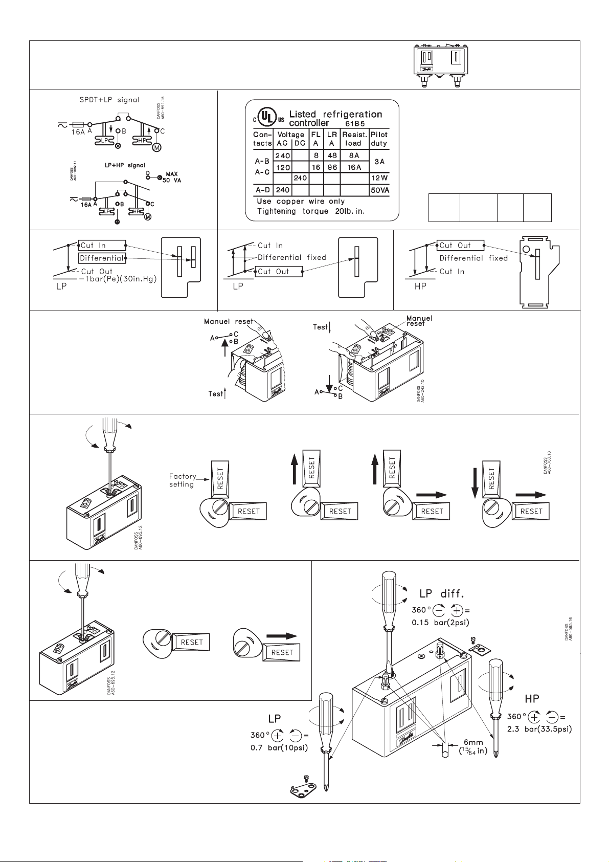
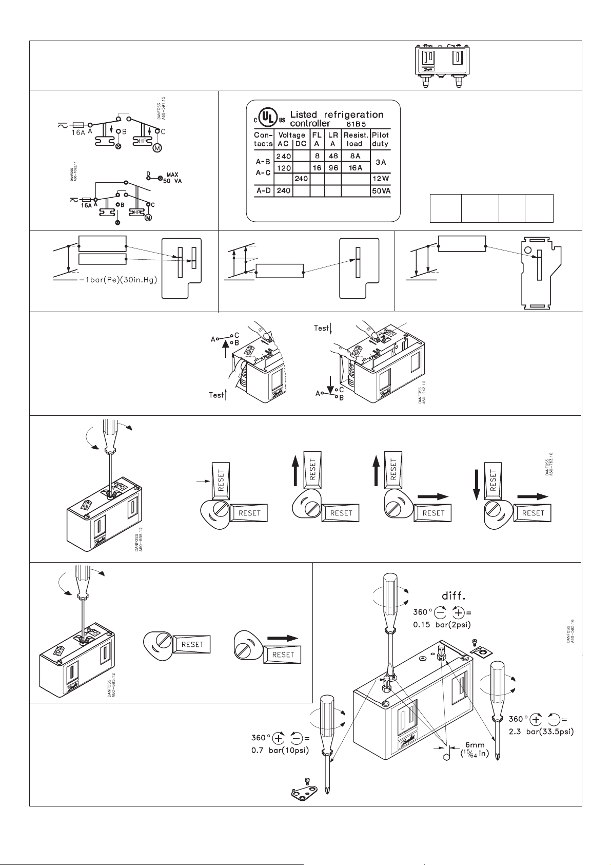
KP 15, 15A, 17W, 17B
When used acc. to UL regulations
LR 112A AC3 16 A 400 V 12 W
-1 bar (Pe)(30in.Hg)
LP, aut. reset LP, man. reset HP
Manual test
Convertible reset
KP 15 060-1154, 060-1220, 060-1261, 060-1263, 060-1283
AC1 16 A DC 11
AC1110 A 220 V
LP-man. LP-auto. LP-auto. LP-man.
HP-man. HP-man. HP-auto. HP-auto.
Convertible reset
KP 17B 060-539366, 060-539466
LP-auto.
HP-man.
LP-auto.
HP-auto.
Page 4

Contents
1 - Introduction
2 - Transportation, storage
3 - Safety measures prior to assembly
4 - Assembly
5 - Leak detection
6 - Vacuum dehydration procedure
7 - Electrical connections
8 - Filling the system
9 - Verification before commissioning
10 - Start up
11 - Troubleshooting
12 - Maintenance
13 - Replacement
14 - User advisory
1 - Introduction
These instructions pertain to Bluestar condensing
units used for refrigeration purposes. They are
intended to provide necessary information
regarding safety features and proper handling of
this product.
Note that this is a general document for the entire
range of condensing units; certain details therefore
may not be applicable to the particular model you
purchased. Please keep your manual and all
relevant information handy for future reference.
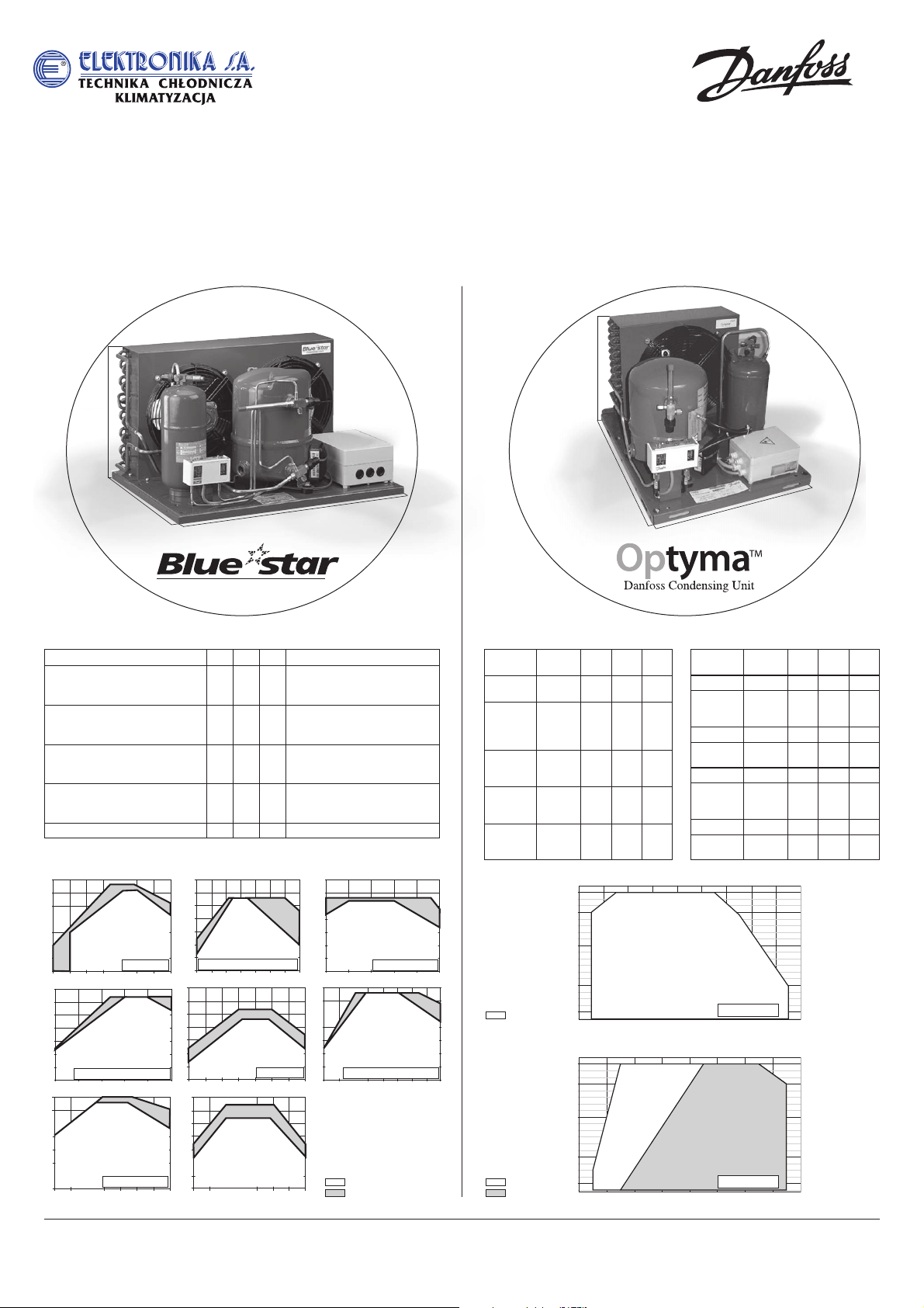
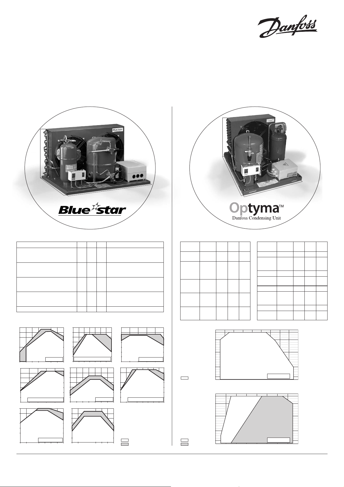
• Equipment description: condensing units are
available under different configurations. They
incorporate a compressor and a fan-cooled
condenser mounted on a base frame. In addition,
they may include a liquid receiver, a pressure
switch, a connecting box and service valves.
• Approved list of refrigerants:
- The MGM, HGM, MCMC and MGMC product
line (fitted with Maneurop
®
MT compressors)
can be used with R22, R12 and R502.
- The MGZ, HGZ, MCZC and MGZC product
line (fitted with Maneurop
®
MTZ compressors)
can be used with R404A, R507A, R134a and
R407C.
- The LGZ, LCHC and LGHC product line (fitted
with Maneurop
®
LTZ or NTZ compressors) can
be used with R404A and R507A.
• Note that Maneurop®compressors are filled
with lubricant before leaving the factory:
- The MT series with mineral oil (ref.160P),
- The MTZ series with polyolester oil (ref. 160PZ),
- The LTZ and NTZ series with polyolester oil
(ref. 160Z).
These lubricants must not be mixed with one another.
• Condensing units must only be used for their
designed purpose(s) and within their scope of
application (refer to Fig. 1).
Condensing units are delivered under nitrogen
gas pressure (between 1 and 2 bar) and hence
cannot be connected as is; please refer to the
"Assembly" section for further details.
Condensing units are not certified for mobile
and explosion-proof applications. Any use of
flammable refrigerant (e.g.hydrocarbons) or air is
also strictly forbidden.
• Under all circumstances, the EN378 (or other
applicable local regulation) requirement must be
fulfilled.
When pressure tests are required on the system,
they are to be performed by qualified personnel, in
paying close attention to potential pressure-rela-
ted hazards and heeding the pressure limits displayed on the compressor nameplate or in the
application guidelines.
Modifications or alterations to the compressor
or receiver (such as brazing on the shell) not
expressly approved by the party responsible for
ensuring compliance could invalidate the user's
authorization to operate the equipment.
2 - Transportation, storage
• The condensing unit must be handled in the
vertical position (maximum offset from the
vertical: 15°). Should the unit be handled in an
upside-down position, its performance may no
longer be insured.
• Beware that all condensing unit handling must
be carried out with extreme caution to avoid any
shocks. Appropriate and safe lifting equipment
is to be used during handling and unpacking.
Be careful with the condenser’s front surface
(note that the condenser side is indicated on
the packaging).
• Any damage noticed on either the packaging
or the product itself upon reception should be
indicated on a Customer Claim addressed to the
shipping company. The same recommendation
applies to all instances when transport instructions
have not been fully respected.
• Please review the safety instructions printed on
the cardboard packaging before storage.
• Verify that the condensing unit is never stored in
an ambient temperature of below -35°C (-31°F) or
above 50°C (122°F).
• Ensure that the condensing unit and its
packaging are not exposed to rain and/or a
corrosive, flammable atmosphere.
3 - Safety measures prior to assembly
• All installation and servicing is to be performed
by qualified personnel in compliance with all
pertinent practices and safety procedures.
• The condensing unit must be located in a
well-ventilated area; air flow through unit shall not
be restricted in any way (refer to Fig.2). Make
sure that the ambient temperature never exceeds
50°C (122°F) during the off-cycle.
• For outdoor installations, provide a shelter or
use a Danfoss condensing unit housing.
• Make certain that the condensing unit can be
mounted onto a horizontal plane with a maximum
slope of 3°.
• Check that the condensing unit model
corresponds to system specifications (capacity,
use of refrigerant, etc.).
• Verify that the power supply corresponds to
compressor and fan motor characteristics (refer
to the condensing unit nameplate for precision).
• Ensure that the refrigerant charging equipment,
vacuum pumps, etc. for HFC refrigerant systems
have been specifically reserved for these refrigerants
and never used with other CFC, HCFC refrigerants.
• Use only clean and dehydrated refrigerationgrade copper tubes as well as silver alloy brazing
material.
• Verify that all system components are
appropriate (use of refrigerant, etc.), clean and
dehydrated before being connected to the
completed assembly.
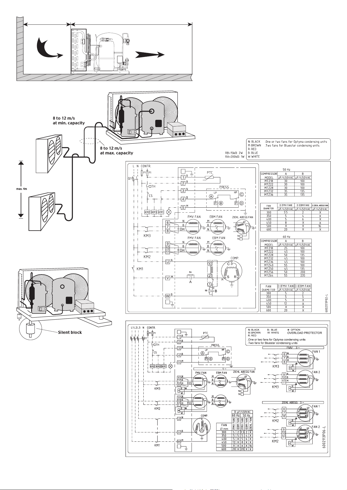
Perform a check on the suction lines: horizontal
sections are to be sloped downwards towards
the compressor. Suction gas velocity must be
high enough to provide for an adequate oil
return.This velocity must be within 8 to 12 m/s in
vertical risers. In horizontal pipes, this velocity
can decrease to 4 m/s. The use of U-trap and
double-suction risers may be required on vertical
sections, but not in excess of 4 m unless a second
U-trap system has been fitted (refer to Fig. 3).
Suction line piping must be insulated in order to
minimize the effects of superheating.
• The piping connected to the compressor must be
configured on the basis of a flexible 3-axis design
to dampen vibrations and designed in such a way
as to prevent free liquid refrigerant migration and
drainage back to the compressor sump.
When installing a liquid receiver or any other
pressure-containing component on the condensing
unit, be sure that these components comply with
the European P.E.D.
Make sure the installation is equipped with
high-pressure safety components (e.g. pressure
switch, pressure relief valve) to prevent against
the bursting of pressure-containing components.
• Note that all local and regional regulations and
safety standards, such as EN378, must be taken
into account when designing, connecting and
running the system.
4 - Assembly
The condensing unit’s time of exposure to
the atmosphere during installation shall be held
to a minimum. The condensing unit is fitted with
suction and liquid copper stubs equipped with
shut-off valves to enable connection to the circuit
without ingress of air or moisture in the unit.
Opening the shut-off valves before connection will
cause moisture contamination of the compressor
lubricant.
• Rubber grommets can be installed under the
condensing unit base frame, as shown in Fig 4,
to prevent vibration interference from other
operating equipment or machinery and to reduce
vibration transmission to the supporting structure.
Before opening the compressor connection
fittings, it is mandatory to connect a 1/4” service
hose to the Schrader fitting on the compressor
shell in order to gradually release the nitrogen
holding charge.
• Ensure that no material enters into the system
while cutting the tubing. Moreover, never drill
holes in the pipe work after installation.
• Avoid flare-type connections and exercise great
care while brazing (use only state-of-the-art
practices); apply a nitrogen gas flow to prevent
oxidation inside the tubing, especially when HFC
refrigerants are being used. All brazing material is
to contain a minimum of 5% silver.
• When brazing, protect the valves and all other
unit components from torch heat damage (painted
surfaces, gaskets, connecting box).
• Note that it is not necessary to remove compressor
shut-off valves for connection to the system,
hence no need to replace associated gaskets.
• Be sure to connect the required safety and control
devices onto compressor shut-off valves or fittings.
• In case of oil return through the Schrader fitting
on the compressor shell, make sure the internal
valve is removed.
Instructions
4
8510198 P03-A © Danfoss Commercial Compressors 03/05
Page 5

5 - Leak detection
Never use oxygen or dry air in order to avoid the
risk of fire or explosion.
• Perform a leak detection test on the complete
system by means of: a dry nitrogen pressure test,
a mixture of nitrogen and the refrigerant to be
used in the system, a helium leak test and/or a
deep vacuum test.
• The test should be long enough in duration to
ensure the absence of any slow leaks in the system.
• Use tools specifically designed for detecting leaks.
• The low side test pressure must not exceed
1.1 x Ps pressure indicated on the compressor
nameplate.
• For high side test pressure, do not exceed
the pressure indicated on the condensing unit
nameplate.
• Whenever the condensing unit is equipped with
suction and liquid shut-off valves, these valves are
to remain in the closed position while performing
the leak test (condensing unit leak test already
performed in the factory).
• Should a leak be discovered, proceed with
repair steps and repeat the leak detection.
• When a deep vacuum leak detection test is
selected, observe the following:
1) The level to reach is 500 µm Hg.
2) Wait 30 min.
3) If pressure increases rapidly, the system is not
airtight. Locate and repair leaks. Restart the
vacuum procedure, followed by steps 1, 2, etc.
4) If pressure increases slowly, the system contains
moisture inside. Break the vacuum with nitrogen
gas and restart the vacuum procedure, followed
by steps 1, 2, etc.
5) Connect the compressor to the system by
opening the valves.
6) Repeat the vacuum procedure, followed by
steps 1, 2, etc.
7) Break the vacuum with nitrogen gas.
8) Repeat the vacuum procedure, steps 1, 2;
a vacuum of 500 µm Hg (0.67 mbar) should be
reached and maintained for 4 hours.This pressure
is to be measured in the refrigeration system, and
not at the vacuum pump gauge.
Do not use a megohmeter or apply power
to the compressor while it is under vacuum, as
this may cause motor winding damage (motor
burn-out).
Do not use colored leak detection fluids. Do
not use chlorofluorocarbon in leak testing systems
designed for HFC fluids.
6 - Vacuum dehydration procedure
Whenever possible (if shut-off valves are present),
the condensing unit must be isolated from the circuit.
It is essential to connect the vacuum pump to both
the LP & HP sides, in order to avoid dead-ending
system parts.
Recommended procedure:
1) Once leak detection has been completed,
2) Pull down the system under a vacuum of 500 µm
Hg (0.67 mbar).
3) When the vacuum level of 500 µm Hg has been
reached, the system must be isolated from the
pump.
4) A vacuum of 500 µm Hg (0.67 mbar) has to be
reached and maintained for 4 hours.This pressure
is to be measured in the refrigeration system, and
not at the vacuum pump gauge.
If pressure increases, restart the leak-detection
procedure (refer to the «Leak detection» section
of this manual if necessary).
V
acuum pump:
A two-stage vacuum pump with gas ballast valve
(0,04-mbar standing vacuum) shall be used; its
capacity is to be consistent with system volume.
Never use the compressor as a vacuum pump. It
is recommended to use large-diameter connection
lines and to connect these lines to the shut-off
valves, rather than to the Schrader connection.
This recommendation allows avoiding excessive
pressure losses.
Moisture lev
el:
At the time of commissioning, system moisture
content may be as high as 100 ppm. During
operation, the liquid line filter dryer must reduce
this level to < 20 ppm.
Additional notes:
• To improve moisture removal, the temperature
of the system should not be lower than 10°C.
• A proper vacuum procedure is even more
important with HFC and polyolester lubricant than
it has “traditionally” been with HCFC (R22) or
CFC and mineral oil.
• For further details, please refer to TI 3-026.
Do not use a megohmeter or apply power to
the compressor while it is under vacuum, as this may
cause motor winding damage (motor burn-out).
7 - Electrical connections
• Make sure the main power supply to the system
has been switched off and isolated, in accordance
with applicable regulations, before performing
any electrical connection.
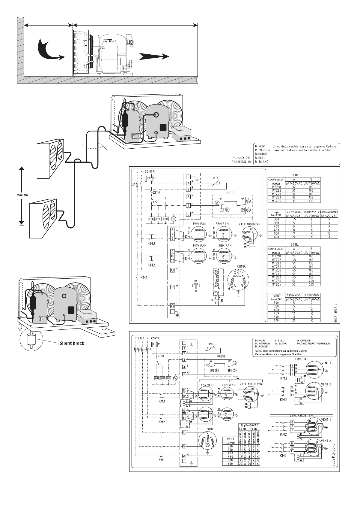
• Please refer to Figs 5 and 6 for typical wiring
connections and examine the specific wiring
diagram located in the electrical box cover.
For further details, refer to the condensing unit
guidelines.
• Note that Maneurop®compressors fitted on
condensing units are protected against overheating
and overloading by an internal safety motor
protector. However, an external manual reset
overload is recommended for protecting the circuit
against over-current.
• The “must trip” value of this overload relay must
be set in accordance with power line sizing and
design and shall never exceed the “A max.” value
stamped on the nameplate.
• On units equipped with an electrical box, all
electrical connections (condenser fan motor,
compressor motor, pressure control switch,
crankcase heater, etc.) have already been wired
at the factory. For single-phase compressors,
start-and-run capacitors are included in the
connecting box.
• The connecting box is equipped with screw type
terminal blocks, for both power and control lines as
well as earth terminals for grounding connections.
• All electrical components must be selected as
per local standards and condensing unit component
requirements.
8 - Filling the system
• Before charging the refrigerant, verify that the oil
level is between 1/4 and 3/4 on the compressor
oil sight glass and/or ensure that the oil charge of
the original compressor is sufficient as regards
system dimension and piping design:
- An additional quantity of oil might be necessary
for line lengths (back and forth) in excess of 20 m.
- In the event additional oil is required, use only an
approved lubricant (refer to the «Introduction»
section of this manual).
• Make sure the refrigerant used to fill the system
is compatible with compressor design. Refer to
the «Introduction» section of this manual for an
approved list of refrigerants.
• Compressor switched off: the liquid refrigerant is
charged into the condenser and/or liquid receiver
in the liquid phase (compulsory for refrigerant
blends).The charge must be asclose to the nominal
system charge as possible in order to avoid both low
pressure operations and excessive superheating
at start-up. Throughout this operation, both
compressor service valves must remain closed.
• Remember that vapor-charging is only appropriate
for pure refrigerants, such as R22.
• To the extent possible, maintain the refrigerant
charge below 2.5 kg per cylinder.Above this limit,
install a system, such as a pump-down cycle or
suction line accumulator, to prevent against liquid
flood-back into the compressor.
• Be sure that the refrigerant charge is suitable for
both winter and summer operations.
9 - Verification before commissioning
Ensure that all service valves are in the open
position before start-up. A closed discharge or
suction service valve may cause serious damage to
the compressor and/or compromise safety device
operation, thereby resulting in potential injury to
personnel.
• Check that all safety devices are operational and
properly set (safety pressure switch set point,
mechanical relief valve if necessary, etc.). Make
sure that these devices comply with both
generally - and locally - applicable regulations
and standards (e.g. EN378).
• When using high-pressure switches or relief
valves, the setting must not exceed maximum
service pressure of any system component. Refer
to the Application Guidelines for relevant condensing
unit pressure safety limits.
• A low-pressure switch is recommended to
prevent operation under vacuum. Use a minimum
setting of 1.2 bar (absolute).
• Verify that all electrical connections are properly
fastened and in compliance with local safety
regulations.
• A compressor crankcase heater is factory
installed, ensure that it has been energized for a
minimum of 12 hours before initial start-up and/or
during prolonged shutdown periods.
10 - Start up
Never start the compressor in the absence of
a refrigerant charge.
• Do not bypass the LP or any other safety
switches during start-up
• Check current draw and voltage levels.
• Monitor the oil sight glass to ensure proper oil return
to the compressor.After 2 to 4 hours of operations
under established conditions, check the oil level
and add oil if necessary (refer to TI bulletin 3-025).
Instructions
5
8510198 P03-A © Danfoss Commercial Compressors 03/05
Page 6

If oil return continues to perform poorly, further
investigation of the piping design is required.
• In all cases, the application limits of the compressor
must be respected; moreover, high superheat
values lead to high discharge temperatures and
decrease compressor capacity. The maximum
discharge temperature is 130°C: operating ata
higher temperature may result in refrigerant
decomposition.
• Under steady-state operating conditions, check
refrigerant piping or capillary tubes for abnormal
vibrations (refrigeration line movement in excess
of 1.5 mm necessitates corrective actions, pipe
brackets, etc.).
• Ensure that refrigerant flow through the liquid
line sight glass (when mounted) is adequate and
that operating temperatures correspond with
system specifications.
• When needed, refrigerant may be added in the
liquid phase, carefully throttling the refrigerant on
the low-pressure side and as far as possible from
the compressor.The compressor must be operating
during this process.
Do not overcharge the system.
11 - Troubleshooting
• Compressor failure to start: verify that the
compressor is hooked up to the power supply;
check the power lead connections and all suitable
capacitors on single-phase models. If these
verifications reveal no abnormality, control the
motor windings with an ohmmeter.
Note: when the internal motor protector has tripped
out, it may take up to several hours to reset and
restart the compressor.
• Compressor failure to build up pressure:
check to make sure that all bypass valves in the
system have not been opened.Also check that all
solenoid valves are in their proper position. If the
internal pressure relief valve is open, the compressor
sump will be warm and the compressor will trip
out on the motor protector. If this happens, it may
take up to 2 or 3 hours to reset and automatically
restart the compressor.
• Abnormal running noise on the system:
- Ensure the absence of any liquid flood-back
to the compressor by means of measuring
the return gas superheat and compressor sump
temperature.The sump should be at least 10K
above the saturated suction temperature under
steady-state operating conditions.
- Check that the fans are running free and without
vibration.
• The high-pressure switch trips out: check
condenser operations (condenser cleanliness,
fan operations, etc.). If above check out OK,
the problem may be due to either refrigerant
overcharging or the presence of a non-condensable
(e.g. air, moisture) in the circuit.
• The low-pressure switch trips out: check
evaporator operations (coil cleanliness, fan
operations, water flow, water filter, etc.), liquid
refrigerant flow and pressure drops (solenoid valve,
filter dryer, expansion valve, etc.), refrigerant charge.
• Low refrigerant charge: the correct refrigerant
charge is given by the liquid sight glass indication,
the condenser delta T in relation to the refrigerant
pressure tables (pressure-temperature), the
superheat and the sub-cooling, etc. (if additional
charge is deemed necessary, refer to the «Filling
the system» section).
• Compressor maximum short cycling: there
must be a minimum delay of five minutes between
two compressor starts. DCC recommends the
compressor should run at least two minutes after
each start, and between each stop and start must
be three minutes standstill. Only during pump
down cycle, the compressor may run much shorter
until the pumpdown pressure has been reached
or when safety devices will prohibit compressor
further operation.
12 - Maintenance
• Proper operations and maintenance of the
condensing units serve to prevent against
system-related problems.The following preventive
maintenance checks, to be performed at regular
intervals, are highly recommended:
- Control operating conditions (evaporating
temperature, condensing temperature,
compressor discharge temperature, temperature
difference on heat exchangers, superheat,
sub-cooling). These conditions must always
remain within compressor operation limits.
- Verify that safety devices are operational and
properly set.
- Check the compressor oil level and quality; this
step may include an acid test, humidity check,
spectrometer analysis, etc. whenever the oil
becomes discolored.
- Ensure that the circuit is leak tight.
- Verify the proper operation of heat exchangers
and, if necessary, clean them.
- Check that the fans are running free (without
vibration) and current draw on the compressor
motor as well as proper voltage balance
between phases.
- Change the filter dryer when necessary.
- Check that all electrical connections are still
adequately fastened.
- Make sure the condensing unit is clean and in
good working order; verify the absence of rust
or corrosion on components under pressure
and electrical connections.
- Make sure the refrigerant charge is suitable for
both winter and summer operation.
• Ensure that periodic in-service inspections
required by local regulations are performed.
13 - Replacement
Precaution must be taken when disconnecting
any components, cutting or drilling holes in the
tubing to ensure that no refrigerant under pressure
is present in the system.
The refrigerant shall not be discharged directly
into the atmosphere; rather, it must be removed
using approved reclamation techniques and
equipment and then safely stored, inaccordance
with applicable legislation.
The presence of refrigerant vapor can displace
air and lead to suffocation. Proper ventilation
is mandatory at all times when servicing the
equipment.
A condensing unit component change must be
carried out in compliance with local regulations.
• Make sure that the main power supply has been
switched off.
• Before replacement, it is necessary to determine
the cause of failure and implement remedial
action. If such analysis and repair are not performed,
repetitive failure may occur. Note that an oil acidity
test always proves helpful indiagnosis when
undertaking compressor replacement.
• Check that the replacement component has the
same electrical and refrigeration performance
characteristics as the original one.
• Whenever piping needs to be modified, please
refer to the «Safety measures prior to assembly»
section.
• For further details on replacement steps,refer to
the previous sections of this manual.
Note:
In the event of compressor motor failure,
flush and clean the entire circuit before replacing
the compressor in order to remove acids and
contaminants. Systematically install a new filter
dryer on the liquid line. Prior to this step (if
necessary), run the system for at least 2 hours
with anti-acid cartridges (in such instances, the
installation of a suction filter might also be required).
After an operating period of approximately 2 weeks,
check the level of oil acidity. If the oil acid test
proves positive, drain and replace the oil, replace
the anti-acid liquid line filter dryer cartridges and
the suction filter previously installed. Repeat oil
and filter dryer replacements until the system is
clean and acid-free.
When there is no longer any sign of acidity, replace
the anti-acid cartridges by the standard model and
remove the suction strainer cartridge as required.
14 - User advisory
Insist that all service operations only be
performed by qualified personnel.
The condensing unit tubing and compressor
surface temperatures may exceed 100°C (212°F)
and cause severe bodily burns.Special precaution
must be taken when working around the compressor
and refrigerant tubing. Moreover, a compressor
in operation can generate very cold surface
temperatures (as low as -45°C / -49°F), there by
exposing personnel to the risk of freezing burns.
Pressure inside the compressor and refrigerant
circuit can reach dangerously high levels (e.g.
abnormal operation, fire,…) leading to personnel
injury if suddenly released; therefore, never drill,
weld or cut the compressor shell and adjacent
tubing (release of liquid refrigerant can cause
flash freezing on exposed skin).
Even though fans are fitted with safety guard
it is recommended not to work on condenser
while fans are running.
Be aware that the product warranty may be
deemed null and void in the following cases:
• Modifications to the unit, unless approved by
Danfoss Commercial Compressors, absence of
nameplate, broken or dented components, shock
marks, etc...
• Compressor opened by the customer or returned
unsealed (i.e. open discharge or suction ports),
• Presence of rust or water inside the condensing
unit circuit,
• Addition of leak-detection fluid in the compressor
lubricant,
• Use of a refrigerant or lubricant not approved by
Danfoss Commercial Compressors.,
• Any deviation from recommended instructions
pertaining to installation, application or maintenance,
• Use in mobile applications (boats, trains, trucks,
etc.) or under explosive atmospheric conditions.
The date of production of the condensing unit is
indicated on the nameplate. Ensure that the model
and serial number information is always transmitted
with any claim filed regarding this product.
Instructions
6
8510198 P03-A © Danfoss Commercial Compressors 03/05
Page 7
8510198 P03-A © Danfoss Commercial Compressors 03/05
Danfoss Commercial
Compressors
INSTRUCTIONS
Bluestar & Optyma
50 Hz L P H 60 Hz
MGM/MGZ 016-018-022-028 700 500 392 MGM/MGZ 018-022
HGM/HGZ 018 HGM/HGZ 018
LGZ 022 LGZ022
MGM/MGZ 032-036-040 800 600 442 MGM/MGZ 028-032-036-040
HGM/HGZ 022-028-032 - HGM036 HGM/HGZ 022-028
LGZ 028-040 LGZ028
MGM/MGZ 050-064-080 1000 700 555 MGM/MGZ 050-064
HGM/HGZ 040-050 -HGZ 036 HGM/HGZ 032-036-040-050
LGZ 044-050 LGZ044-050
MGM/MGZ 100-125-144-160 1200 800 671 MGM/MGZ 080-100-125-144-160
HGM/HGZ 064-080-100 HGM/HGZ 064-080-100
LGZ 088-100 LGZ088-100
HGM/HGZ 125-144-160 1500 870 975 HGM/HGZ 125-144-160
50 Hz
Comp-
LPH
resseur
MCZC030 MTZ18
500 620 451
MCZC038 MTZ22
MCZC048 MTZ28
MCZC054 MTZ32
630 650 605
MCZC060 MTZ36
MCZC068 MTZ40
MCZC086 MTZ51
MCZC096 MTZ57 755 700 656
MCZC108 MTZ65
MCZC121 MTZ73
MCZC136 MTZ81 900 900 759
MCZC171 MTZ100
MGZC215 MTZ125
MGZC242 MTZ144 1350 820 759
MGZC271 MTZ160
50 Hz
Comp-
LPH
resseur
LCHC048 NTZ048 500 620 451
LCHC068 NTZ068
LCHC096 NTZ096 630 650 605
LCHC108 NTZ108
LCHC136 NTZ136 755 700 656
LCHC215 NTZ215
900 900 759
LCHC271 NTZ271
LGHC048 NTZ048 700 500 392
LGHC068 NTZ068
LGHC096 NTZ096 800 600 442
LGHC108 NTZ108
LGHC136 NTZ136 1000 700 555
LGHC215 NTZ215
1200 800 671
LGHC271 NTZ271
L
P
H
L
P
H
CONDENSING UNITS
-25 -15 -5 5 10
50
45
35
25
15
HGM R22
-30 -20 -10 0 5
50
45
35
25
15
MGZ R404A - R507A
-15
-35
25 -30
50
45
35
25
15
LGZ R404A - R507A
-30 -20 -10 0
10
50
45
35
25
15
HGZ R404A - R507A
-15
-5
51520
50
45
35
25
15
HGZ R134a
Temperature évaporée (C°)
Temperature ambiante (C°)
SH = 10K
Surchauffe limitée
SH = 10K
Application MBP Application LBP
SH = 10 K
RGT = 20 °C
Fig. 1
50
45
35
25
MGZ R134a
-5
510
50
45
35
25
15
-25 -15 -5 5 10
MGM R22
15
-15
46
43
38
T° amb (°C)
32
28
-30 -25 -20 -15 -10 -5 0 5 10
46
43
Plage d'application MBP
Plage d'application LBP
T° evap (°C)
R404A/R507A
38
T° amb (°C)
32
27
-45 -40 -35 -30 -25 -20 -15 -10
R404A/R507A
T° evap (°C)
Page 8
8
8510198 P03-A © Danfoss Commercial Compressors 03/05
Fig. 4
Fig. 3
Fig. 5
1 x hauteur de batterie Espace minimum : 2 x longueur
Fig. 2
Fig. 6
8 à 12 m/s
à capacité minimun
8 à 12 m/s
à capacité maximun
Page 9
9
8510198 P03-A © Danfoss Commercial Compressors 03/05
SPDT+BP Signal
BP
BP+HP Signal
KP 15, 15A, 17W, 17B
When used acc. to UL regulations
BP
Point de
declenchement
Differentiel
Point de renclenchement
BP BP HP
Fil de cuivre uniquement
Couple de serrage 20 Nm
Point de
declenchement
Differentiel fixe
Point de
renclenchement
-1 bar (Pe)(30in.Hg)
BP, man. ResetBP, auto. Reset
Reset manuel
Reset manuel
Reset manuel
Reset manuel
Test manuel
Reset convertible
KP 15 060-1154, 060-1220, 060-1261, 060-1263, 060-1283
Reglage
d'usine
LR 112A AC3 16 A 400 V 12 W
AC1 16 A DC 11
AC1110 A 220 V
Point de
renclenchement
Differentiel fixe
Point de declenchement
HP
BP-man BP-auto BP-auto BP-man
HP-man HP-man HP-auto HP-auto
Reset convertible
KP 17B 060-539366, 060-539466
BP-auto
HP-man
BP-auto
HP-auto
BP
HP
BP
Page 10

Sommaire
1 - Introduction
2 - Transport, entreposage
3 - Mesures de sécurité avant montage
4 - Montage
5 - Détection des fuites
6 - Tirage au vide et déshydratation
7 - Connexions électriques
8 - Charge réfrigérant
9 - Vérification avant démarrage
10 - Mise en service
11 - Dépannage
12 - Maintenance
13 - Remplacement
14 - Conseils aux utilisateurs
1 - Introduction
Ces instructions s’appliquent aux groupes de
condensation Bluestar®utilisés pour les systèmes
de réfrigération. Elles fournissent les informations
nécessaires relatives à la sécurité, à la manutention
et aux méthodes d’utilisation de ces produits.
Veuillez conserver ce manuel d’instructions et toute
information pouvant s’avérer utile ultérieurement.
Note : ce document est générique et couvre
l’ensemble de la gamme des groupes de
condensation Bluestar
®
, certains points pouvant
ne pas concerner le modèle dont vous vous êtes
rendu acquéreur.
• Description de l’équipement : les groupes de
condensation comprenent un compresseur et un
condenseur à air montés sur un châssis. Ils peuvent
être disponibles sous différentes configurations.
En outre, ces configurations peuvent comprendre
un réservoir liquide, un pressostat, une boîte de
connexion, des vannes de service et une notice
d’instructions.
• Liste des réfrigérants autorisés :
- Les séries MGM, HGM, MCMC et MGMC
(équipées de compresseurs Maneurop
®
MT)
peuvent être utilisées avec les réfrigérants
R22, R12 et R502.
- Les séries MGZ, HGZ, MCZC et MGZC
(équipées de compresseurs Maneurop
®
MTZ)
peuvent être utilisées avec les réfrigérants
R404A, R507A, R134a et R407C.
- Les séries LGZ, LCHC et LGHC (équipées
de compresseurs Maneurop
®
LTZ ou NTZ)
peuvent être utilisées avec les réfrigérants
R404A et R507A.
• Les compresseurs Maneurop
®
reçoivent une
charge de lubrifiant en usine :
- Les séries MT : huile minérale (réf.160P),
- Les séries MTZ : huile polyolester(réf.160PZ).
- Les séries LTZ et NTZ : huile polyolester (réf.
160Z).
Ces lubrifiants ne doivent pas être mélangés à
d’autres types de lubrifiants.
• Les groupes de condensation Bluestar
®
doivent
uniquement être utilisés dans le cadre de leur
plage d’application spécifique (voir Figure 1) et
en conformité avec les guides et recommandations
d’application publiés par le constructeur.
Les groupes de condensation Bluestar
®
sont
livrés sous pression d’azote (entre 1 et 2 bars) et
ne peuvent donc pas être connectés tels quels ;
veuillez vous reporter à la rubrique «Montage»
pour plus de détails.
Les groupes de condensation ne sont
pas certifiés pour des applications mobiles et
anti-déflagrantes. Par ailleurs, leur utilisation avec
des réfrigérants inflammables (hydrocarbones
par exemple) ou de l’air est strictement interdite.
• En toutes circonstances, les exigences de la
norme européenne EN378 (ou à défaut de la
réglementation locale) doivent être satisfaites.
Tout test de pression du système doit être
effectué par un personnel qualifié, portant la plus
grande attention aux dangers potentiels liés à
la pression et respectant les limites de pression
indiquées sur la plaque signalétique du compresseur
et du groupe ou dans les Instructions.
Toute modification ou altération au compresseur
ou réservoir liquide (telle qu’un brasage sur
l’enveloppe) non spécifiquement approuvée par
l’organisme chargé de certifier la conformité
pourra invalider le droit de l’utilisateur d’exploiter
l’équipement.
2 - Transport, entreposage
• Le groupe de condensation doit être
manutentionné en position verticale (inclinaison
maximum par rapport à la verticale : 15°). Si le
groupe de condensation est manipulé à l’envers,
son fonctionnement peut en être affecté.
• Le groupe de condensation doit être manipulé
avec la plus extrême prudence afin d’éviter tout
choc éventuel. Un équipement de manutention et
de levage approprié et sûr devra être utilisé.
Notez la fragilité de la surface frontale du condenseur
(voir mentions portées sur l’emballage).
• Tout dommage constaté sur l’emballage ou sur
le produit lui-même au moment de la livraison
devra faire l’objet d’une réclamation adressée
au transporteur. Les mêmes recommandations
s’appliquent aux cas de non-respect des instructions
de transport.
• Veuillez lire soigneusement les consignes de
sécurité imprimées sur l’emballage carton avant
l’entreposage.
• Vérifiez que le groupe de condensation entreposé
ne sera pas soumis à une température ambiante
inférieure à -35°C (-31°F) ou supérieure à 50°C
(122°F).
• Assurez-vous que le groupe de condensation
et son emballage ne sont pas exposés aux
intempéries et/ou à des substances corrosives ou
inflammables.
3 - Mesures de sécurité avant montage
• Toute opération de montage et d’entretien doit être
effectuée par un personnel qualifié conformément
à l’ensemble des pratiques courantes et aux
mesures de sécurité de la profession.
• Le groupe de condensation doit être installé dans
un endroit suffisamment ventilé ; le débit d’air au
condenseur ne doit subir aucune restriction (voir
Figure 2). La température ambiante ne doit
jamais dépasser 50°C (122°F) pendant les cycles
d’arrêt.
• Pour les installations extérieures, prévoir un abri
ou utiliser l’accessoire «capotage de protection»
Danfoss-Maneurop.
• Le groupe de condensation doit être monté sur
un plan horizontal - pente maximale 3°.
• Vérifiez que le modèle de groupe de condensation
correspond aux spécifications du système
(capacité, réfrigérant à utiliser, etc.).
• Vérifiez que l’alimentation électrique correspond
aux caractéristiques du compresseur et des
ventilateurs (pour plus de précision, voir la plaque
signalétique du groupe de condensation).
• Assurez-vous que les équipements de charge
réfrigérant, pompe à vide, etc. pour les systèmes
HFC ont été spécifiquement réservés pour ces
réfrigérants et ne seront jamais utilisés avec
d’autres réfrigérants CFC, HCFC, par exemple.
• N’utilisez que des tubes en cuivre de qualité
frigorifique, propres et déshydratés ainsi que de
la brasure à base d’argent.
• Vérifiez que tous les composants du système
sont appropriés (adaptés au réfrigérant utilisé,
correctement dimensionnés, etc.), propres et
déshydratés avant d’être connectés à l’installation.
• Vérifiez les lignes d’aspiration : les sections
horizontales doivent être inclinées vers le bas
en direction du compresseur. La vitesse du gaz
d’aspiration doit être suffisamment élevée pour
offrir un retour d’huile suffisant. Cette vitesse doit
se situer dans une fourchette de 8 à 12 m/s dans
des colonnes verticales. Dans le cas des tubes
horizontaux, une vitesse de l’ordre de 4 m/s est
suffisante. L’utilisation de siphons en «U» et de
double colonnes montantes d’aspiration pourra
être nécessaire pour les sections verticales.
Au-delà de 4 m de colonne montante un deuxième
siphon en «U» devra être installé (voir Figure 3).
Les tuyauteries d’aspiration doivent être isolées
afin de minimiser les effets de la surchauffe.
• Le dessin du tube d’aspiration connecté au
compresseur doit non seulement être conçu sur
la base d’une structure souple selon 3 axes pour
amortir les vibrations mais aussi de façon à
empêcher l’écoulement de réfrigérant liquide
dans le carter pendant les périodes d’arrêt.
Lors de l’installation d’un réservoir liquide ou
de tout autre composant sous pression sur le
groupe de condensation, assurez-vous de leur
conformité à la directive européenne P.E.D. ou à
toute autre norme locale «Appareil à pression».
L’installation doit être équipée d’organes
de sécurité haute pression (tels que pressostat,
soupape de sécurité) afin d’empêcher l’éclatement
des composants sous pression.
• Notez que toutes les normes et réglementations
de sécurité locales et régionales, telles que la
norme européenne EN378, doivent être prises en
considération au moment de la conception, du
montage et de la mise en service du système.
4 - Montage
Pendant l’installation, l’ouverture du groupe
à l’atmosphère doit être limitée à une durée
minimale (moins d’une demi-heure). Le groupe
de condensation est équipé de vannes d’arrêt
aspiration et liquide avec manchons en cuivre
afin de permettre la connexion au circuit sans
entrée d’air ou d’humidité à l’intérieur du groupe.
L’ouverture de ces vannes d’arrêt avant la connexion
entraînera la contamination du lubrifiant par
l’humidité.
Instructions
10
8510198 P03-A © Danfoss Commercial Compressors 03/05
Page 11

• Des silentblocs en caoutchouc peuvent être
installés sous le châssis du groupe de condensation,
(voir figure 4) afin d’empêcher des interférences
vibratoires provenant d’autres appareils ou machines
et de réduire la transmission de vibrations à la
structure sur laquelle le groupe est installé.
Avant démontage d’un quelconque composant
du groupe, libérez graduellement la pression
d’azote interne (raccords 1/4'' flare des vannes
d’arrêt ou Schrader du compresseur).
• Veillez à la propreté interne des tuyauteries
après coupe, ébavurage, etc. De plus, ne jamais
percer la tuyauterie après montage.
• Evitez les connexions vissées de type «flare». En
cas de connexion brasée, employez un flux d’azote
pour éviter l’oxydation interne de la tuyauterie,
notamment lorsque les réfrigérants HFC sont
utilisés. Les baguettes de brasage doivent contenir
un taux d’argent d’au moins 5%.
• Au moment du brasage, protégez les vannes
d’arrêt ou tout autre composant du groupe de la
chaleur dégagée par le chalumeau (surfacespeintes, joints, boitier électrique).
• Notez qu’il n’est pas nécessaire de démonter
les vannes d’arrêt du compresseur pour le
raccordement brasé au système.Il n’est donc pas
nécessaire de remplacer les joints associés.
• Vérifiez que les dispositifs de sécurité ou de
régulation pressostatique sont correctement
branchés sur les vannes d’arrêt ou sur les raccords.
• Dans le cas d’un système de retour d’huile par
le Schrader BP du compresseur, retirez la valve
interne du raccord.
5 - Détection des fuites
Ne jamais utiliser d’oxygène ou d’air sec,
risques d’incendie ou d’explosion.
• Effectuez un test de détection des fuites sur
l’ensemble du système en utilisant les méthodes
suivantes : test de pression à l’azote déshydraté
ou un mélange d’azote et de réfrigérant prévu
pour le système, test de fuite à l’hélium et/ou test
de tirage au vide poussé.
• La durée du test doit être suffisante pour garantir
l’absence de micro fuites sur le circuit.
• Utilisez les outils spécialisés conçus pour la
détection des fuites.
• La pression du test côté basse pression ne doit
pas dépasser 1,1 x la pression Ps indiquée sur la
plaque signalétique du compresseur.
• Le test côté haute pression ne doit pas dépasser
la pression indiquée sur la plaque signalétique du
groupe.
• Lorsque le groupe est équipé de vannes d’arrêt
d’aspiration et de refoulement, ces vannes doivent
rester en position fermée durant le test de détection
(une détection des fuites sur le groupe ayant déjà
été réalisée en usine).
• En cas de fuite, procédez aux réparations et
renouvelez le test de détection.
• Si un test de détection des fuites par tirage
au vide poussé a été choisi, observez les
recommandations suivantes :
1) Le niveau de vide à atteindre est de 500 µm Hg.
2) Attendez 30 minutes.
3) Si la pression augmente rapidement, le système
n’est pas étanche. Localisez et réparez les fuites.
Redémarrez la procédure de tirage au vide et
répétez les étapes 1, 2, etc.
4) Si la pression augmente lentement, cela dénote
une présence d’humidité à l’intérieur du système.
Cassez le vide avec de l’azote et redémarrez la
procédure de tirage au vide (étapes 1, 2, etc.)
5) Mettre en communication le compresseur avec
le système en ouvrant les vannes.
6) Répétez la procédure de tirage au vide (étapes
1, 2, etc.)
7) Cassez le vide avec de l’azote.
8) Répétez la procédure de tirage au vide (étapes
1, 2) ; un niveau de vide de 500 µm Hg (0,67 mbar)
doit être atteint et maintenu pendant quatre
heures. Ce niveau de vide doit être mesuré à
l’un des raccords du système et non pas au
manomètre de la pompe à vide.
Ne pas utiliser de mégohmmètre et ne pas
mettre sous tension le moteur du compresseur
lorsque le système est sous vide. Risques
de court-circuit interne entre les bobinages du
moteur.
Ne pas utiliser d’additifs pour la détection des
fuites.
Ne pas utiliser de CFC/HCFC comme fluide
traceur de détection des fuites dans le cas
d’installations prévues pour HFC.
6 - Tirage au vide et déshydratation
Lorsque cela est possible (compresseurs équipés
de vannes d’arrêt), le compresseur devra rester
isolé du circuit. Connectez la pompe à vide
aux deux côtés haute pression (HP) et basse
pression (BP) pour un tirage au vide du circuit
dans sa totalité.
Procédure recommandée :
1) Confirmez l’absence de fuites par un test de
détection.
2) Procédez à un tirage au vide jusqu’à 500 µm
Hg (0,67 mbar).
3) Quand un niveau de vide de 500 µm Hg est
atteint, isolez la pompe à vide du circuit.
Ce niveau de vide de 500µm Hg (0,67 mbar) doit
être atteint et maintenu pendant quatre heures.
Mesurez le niveau de vide sur le circuit plutôt
qu’au niveau de la pompe à vide.
Si une remontée de pression est observée,
redémarrer la procédure de détection des fuites
(se reporter à la section «Détection des fuites»
de ces instructions si nécessaire).
P
ompe à vide :
Une pompe à vide double étage avec ballast
(avec capacité de vide de 0.04 mbar) devra être
utilisée, son volume balayé doit être adapté au
volume interne du système. Ne jamais utiliser le
compresseur comme pompe à vide.
Utilisez des raccords et flexibles de gros diamètre
et les connecter aux vannes d’arrêt plutôt qu’au
raccord Schrader. Cette mesure permet d’éviter
des pertes de charge excessives.
Niv
eau d’humidité :
Au moment de la mise en service, le taux
d’humidité du circuit peut atteindre un niveau aussi
élevé que 100 ppm. Pendant le fonctionnement,
le filtre déshydrateur liquide doit réduire ce niveau
à < 20 ppm.
Notes supplémentaires :
• Pour améliorer la déshydratation du circuit, la
température ne doit pas être inférieure à 10°C.
• Une procédure appropriée de tirage au vide
est encore plus importante avec les HFC et les
lubrifiants polyolester que dans une situation
«classique» avec réfrigérant HCFC (R22) ou
CFC et huile minérale.
• Pour plus d’informations, vous reporter au bulletin
technique TI 3-026.
Ne pas utiliser de mégohmmètre ou effectuer
la mise sous tension du compresseur lorsque le
circuit est sous vide, risque de court circuit du
moteur (moteur brulé).
7 - Connexions électriques
• Vérifiez que l’alimentation électrique principale
du système a été coupée et isolée, conformément
aux règles en vigueur, avant d’effectuer toute
opération de raccordement.
• Se référer aux figures 5 et 6 pour les types
de câblage en monophasé et triphasé et consulter
le schéma de câblage spécifique de l’unité
situé dans la boite de raccordement électrique.
Pour plus de détails, vous référer aux guides
d’application.
• Notez que les compresseurs Maneurop
®
montés
sur les groupes de condensation sont protégés
contre la surchauffe et la surcharge grâce à
une protection moteur interne. Néanmoins, un
disjoncteur de surcharge à réarmement manuel
externe est recommandé pour protéger le circuit
contre les surintensités.
• Note : La valeur du «seuil de déclenchement»
de ce disjoncteur doit être réglée en fonction du
type de compresseur et du type d’alimentation.
Elle ne doit en aucun cas excéder la valeur
“A max.” indiquée sur la plaque signalétique.
• Pour les unités équipées d’une boite de
raccordement, tous les composants électriques
(moteur de ventilateur, moteur de compresseur,
pressostat, réchauffeur de carter, etc.) ont été
câblés en usine. Pour les compresseurs
monophasés, les condensateurs permanents et
de démarrage ainsi que le relais de démarrage
sont inclus dans la boîte de raccordement.
• La boîte de raccordement est équipée avec des
barrettes de connexion à visser, pour les lignes
de puissance, les circuits de contrôle et la mise à
la terre.
Tous les composants électriques doivent être
sélectionnés selon les normes locales en vigueur
et selon le type de groupe de condensation.
Instructions
11
8510198 P03-A © Danfoss Commercial Compressors 03/05
Page 12

8 - Charge réfrigérant
• Avant de charger le réfrigérant, vérifiez que
le niveau de l’huile est situé entre 1/4 et 3/4
du voyant d’huile et/ou assurez-vous que la
charge en huile d’origine du compresseur est
suffisante parrapport à la taille du système et à
la configuration de la tuyauterie :
- Une quantité supplémentaire d’huile peut être
nécessaire pour des longueurs de tuyauteries
(aller-retour) dépassant 20 m.
- En cas d’appoint d’huile, utilisez uniquement
des lubrifiants autorisés (se reporter à la section
«Introduction» de ces instructions).
Pour toute information nécessaire sur les appoints
d’huile au compresseur, se référer au bulletin
technique TI 3025.
• Vérifiez que le réfrigérant utilisé pour la charge
du système est compatible avec le type de
compresseur utilisé. Se reporter à la rubrique
«Introduction» de ce manuel pour une liste des
réfrigérants autorisés.
• Compresseur à l’arrêt : le réfrigérant liquide
est chargé dans le condenseur et le réservoir
liquide en phase liquide (obligatoire pour tous les
réfrigérants zéotropes). Cette charge doit se
rapprocher le plus possible de la charge nominale
afin d’éviter un fonctionnement à trop basse
pression ainsi qu’une surchauffe excessive à
l’aspiration. Pendant l’opération de charge
compresseur à l’arrêt, les deux vannes de service
du compresseur doivent rester fermées.
• La charge réfrigérant en phase vapeur ne peut
être effectuée qu’avec des réfrigérants purs, tels
que le R22.
• Dans la mesure du possible et en fonction du
type d’installation, maintenir la charge de réfrigérant
à une valeur inférieure à 2,5 kg par cylindre
(exemple : compresseur 2 cylindres = 5 kg). Si
cette charge excède la charge limite, prévoir un
cycle de tirage au vide simple à l’arrêt ou une
bouteille anti-coups de liquide à l’aspiration, afin
de protéger le compresseur.
• Vérifiez que la charge de réfrigérant est adaptée
pour un fonctionnement en hiver comme en été.
9 - Vérification avant démarrage
Assurez-vous que toutes les vannes de service
sont en position ouverte avant le démarrage.Une
vanne de refoulement ou d’aspiration fermée
pourrait gravement endommager le compresseur
et/ou rendre inopérants les dispositifs de sécurité,
exposant ainsi le personnel à un risque de blessure.
• Vérifiez que tous les organes de sécurité sont
en bon état de marche et bien réglés (point de
réglage des pressostats et autres vannes ou
soupapes de sécurité, etc.). Veillez à ce que ces
dispositifs soient conformes aux réglementations
et normes en vigueur tant au niveau général
qu’au niveau local (par exemple : norme
européenne EN378).
• Le réglage des pressostats haute pression ou
des soupapes de sécurité ne doit jamais dépasser
la pression de service maximale d’un quelconque
composant du système. Se reporter au guide
d’application pour les pressions maximum de
sécurité du groupe de condensation.
• L’utilisation d’un pressostat de sécurité basse
pression est recommandée pour empêcher un
fonctionnement sous vide. Réglage minimum
recommandé : 1.1 bar (absolu).
• Vérifiez que toutes les connexions électriques
sont bien serrées et conformes aux réglementations
de sécurité en vigueur au niveau local.
• Un réchauffeur de carter a été installé en usine
sur le compresseur ; il doit être mis sous tension
au minimum 12 heures avant la première mise
en service et/ou lors du démarrage après une
période d’arrêt prolongée.
10 - Mise en service
Ne jamais démarrer le compresseur sous
vide ou en l’absence d’une charge de réfrigérant
(risque de claquage moteur).
• Ne jamais court-circuiter le pressostat BP ou
tout autre dispositif de sécurité lors du démarrage.
• Vérifiez la tension d’alimentation et le courant
absorbé.
• Vérifiez le sens d’orientation des ventilateurs de
condenseur (débit d’air vers le compresseur).
• Réglage de la surchauffe d’aspiration : la
surchauffe optimale à l’aspiration du compresseur
est de l’ordre de 10K, la surchauffe maximum
autorisée se situant à 30K.
• Dans tous les cas, les limites d’application du
compresseur doivent être respectées. En outre,
des valeurs élevées de surchauffe conduisent
à des hautes températures de refoulement et
font diminuer la capacité du compresseur. La
température maximale de refoulement est de
130°C : le fonctionnement à une température
supérieure peut engendrer la décomposition du
réfrigérant.
• En régime de fonctionnement établi, contrôlez
les vibrations des tuyauteries et tubes capillaires;
des vibrations anormales (déplacement de la
tuyauterie supérieur à 1.5 mm) nécessitent des
actions correctives telles que des supports de
tuyauteries etc.).
• Vérifier le retour d’huile au compresseur à l’aide du
voyant d’huile. Après une durée de fonctionnement
de 2 à 4 heures aux conditions nominales, vérifiez
le niveau d’huile et, si nécessaire, réalisez un
appoint (voir bulletin technique TI2-025). Si le
retour d’huile au compresseur ne s’améliorait
pas, des investigations plus approfondies sur la
configuration des tuyauteries seraient nécessaires.
• Vérifiez que la charge de réfrigérant est
suffisante à l’aide du voyant liquide (si le circuit en
est équipé) et contrôlez que les températures de
fonctionnement correspondent aux spécifications
du système.
• Si besoin est, un complément de charge
peut être effectué en phase liquide, côté basse
pression. Le liquide doit être injecté aussi loin que
possible du compresseur en étranglant le débit
afin d’éviter tout risque de coup de liquide.
Le compr
esseur doit être en marche pendant
ce pr
ocessus.
Evitez une charge excessive de réfrigérant
dans le système.
11 - Dépannage
• Problème de démarrage du compresseur :
vérifiez l’alimentation électrique du compresseur
et contrôlez les connexions de puissance.
Vérifiez les connexions en amont ainsi que les
condensateurs pour les modèles monophasés. Si
ces vérifications ne montrent aucune anomalie,
testez la continuité des bobinages du moteur
avec un ohmmètre (coupure de la protection
interne).
Note : lorsque la protection interne du moteur
se déclenche, plusieurs heures peuvent être
nécessaires à son réarmement et au redémarrage
du compresseur.
• Le compresseur ne pompe pas : contrôlez
que les vannes/soupapes de sécurité du système
ne sont pas ouvertes. Vérifiez également que
toutes les électro-vannes sont en position normale.
Si la soupape de sécurité interne est ouverte,
l’enveloppe du compresseur sera chaude et le
compresseur déclenchera sur la protection
moteur. Si cela se produit, le réarmement peut
prendre deux à trois heures.
• Bruit de fonctionnement anormal : vérifiez
l’absence de retour de liquide au compresseur
en mesurant la surchauffe des gaz d’aspiration
et la température de refoulement du compresseur.
La température du carter d’huile doit se
situer au moins 10K au-dessus de la température
d’aspiration saturée en régime de fonctionnement
permanent. Vérifiez que les ventilateurs tournent
librement et sans vibration.
• Le pressostat de sécurité haute pression se
déclenche : contrôlez le condenseur (propreté,
fonctionnement du ventilateur, débit d’eau, réglage
de la vanne pressostatique, filtre, etc.). Si ces
vérifications se révèlent négatives, l’origine
du problème peut être soit une surcharge de
réfrigérant soit la présence d’incondensables
dans le circuit (air).
• Le pressostat de sécurité basse pression se
déclenche : contrôlez le fonctionnement de
l’évaporateur (propreté de la batterie, fonctionnement
du ventilateur, débit d’eau, encrassement des
filtres, etc.), le débit du réfrigérant liquide et
les pertes de charge (vanne solénoïde, filtre
déshydrateur, détendeur, etc.), la charge de
réfrigérant.
• Une charge de réfrigérant trop faible :
l’indication d’une charge de réfrigérant
appropriée est donnée par l’état du voyant
liquide, le delta T au condenseur par rapport aux
tables du réfrigérant (pression-température),
la surchauffe et le sous refroidissement, etc. (si
un appoint de charge s’avère nécessaire, se
reporter au chapitre «Charge réfrigérant»).
• Fonctionnement en court cycle : cinq minutes
minimum entre deux démarrages du compresseur.
DCC recommande deux minutes au moins de
Instructions
12
8510198 P03-A © Danfoss Commercial Compressors 03/05
Page 13

fonctionnement après chaque démarrage, et
entre chaque arrêt et démarrage, trois minutes
d’arrêt. Le fonctionnement en pump down peut
seul autoriser des temps de fonctionnement
plus courts, jusqu’à obtention de la pression
recherchée, ou lorsque les organes de sécurité
imposent un arrêt.
12 - Maintenance
• Des opérations d’entretien préventif du
système ou de l’installation permettent d’éviter
des problèmes compresseur dont la cause
proviendrait d’un dysfonctionnement du système.
Les vérifications suivantes de maintenance
préventive périodique sont vivement conseillées :
- Contrôler les conditions de fonctionnement du
compresseur (température d’évaporation,
température de condensation, température
de refoulement de compresseur, la différence
de température sur les échangeurs de
chaleur, surchauffe, sous-refroidissement).
Ces paramètres de fonctionnement doivent
toujours respecter les limites de la plage
d’utilisation du compresseur.
- Vérifiez que les dispositifs de sécurité sont
tous opérationnels et correctement réglés.
- Contrôlez le niveau d’huile compresseur et
son aspect. En cas de changement de couleur,
vérifiez sa qualité. Ceci peut inclure un test
d’acidité, un contrôle d’humidité, une analyse
spectrométrique, etc.
- Vérifiez l’étanchéité du circuit frigorifique.
- Vérifiez le fonctionnement des échangeurs
de chaleur et procédez à leur nettoyage, si
nécessaire.
- Contrôlez le bon fonctionnement des ventilateurs
(absence de vibrations), contrôlez le courant
absorbé par le moteur du compresseur ainsi
que l’équilibre de tension entre phases.
- Changez le filtre déshydrateur liquide, si
nécessaire.
- Contrôlez le serrage de toutes les connexions
électriques.
- Assurez-vous de la propreté et du bon état de
marche du groupe de condensation ; vérifiez
l’absence de rouille ou de corrosion sur tous
les composants sous pression et sur les
connexions électriques.
- Assurez-vous que la charge de réfrigérant est
adaptée à un fonctionnement toute saison, été
comme hiver.
• Vérifiez que les inspections périodiques du
fonctionnement exigées par les réglementations
locales ont été effectuées.
13 - Remplacement
S’assurer de l’absence de réfrigérant sous
pression dans le circuit lors de la dépose d’un
quelconque composant, de la découpe de
tuyauteries ou autres travaux de perçage ou de
démontage d’organes sous pression.
Ne pas libérer le réfrigérant de l’installation
à l’atmosphère. Utiliser des techniques et du
matériel de récupération approuvés pour un
stockage respectant la législation en vigueur.
La présence de vapeur de réfrigérant dans
un local fermé peut entraîner l’asphyxie. Une
ventilation suffisante est obligatoire lors de toute
intervention sur le système.
Tout remplacement d'un composant du
groupe de condensation doit s’effectuer selon les
réglementations locales en vigueur.
• Assurez-vous que l’alimentation électrique
principale a été coupée.
• Avant remplacement, déterminez la cause de
la panne et effectuez les réparations nécessaires.
Si cette analyse et ces réparations ne sont pas
réalisées, des pannes répétitives peuvent se
produire. Notez qu’un test d’acidité d’huile s’avère
toujours utile en tant que diagnostique lors d’un
remplacement de compresseur.
• Vérifiez que le composant de remplacement
présente les mêmes caractéristiques électriques
et de puissance frigorifique que l’original.
• Lorsque des modifications de tuyauterie sont
nécessaires, veuillez vous référer au chapitre
«Mesures de sécurité avant montage».
• Pour de plus amples renseignements sur les
procédures de remplacement, se reporter aux
chapitres précédent.
Note :
En cas de panne moteur du compresseur,
vidangez et nettoyez le circuit avant remplacement
du compresseur afin d’éliminer les acides et tout
autre contaminant. D’une manière systématique,
installez un nouveau filtre déshydrateur de
ligne liquide. Au préalable (si nécessaire), faire
fonctionner le système au minimum 2 heures
avec des cartouches de filtre anti-acide (dans les
cas de contamination sévère, l’utilisation de filtre
d’aspiration peut également s’avérer nécessaire).
Après un fonctionnement d’environ 2 semaines,
vérifiez le niveau d’acidité de l’huile. Si ce test est
positif, vidangez et remplacez l’huile, remplacez
également les cartouches du filtre déshydrateur
par des cartouches anti-acide ainsi que les
cartouches du filtre d’aspiration installé
précédemment. Répétez ces remplacements
d’huile et cartouches de filtre jusqu’à ce que le
système soit propre et exempt de tout acide.
Quand il n’y a plus aucune trace d’acide,
remplacez les cartouches anti-acides par le
modèle standard et retirez la cartouche du filtre
d’aspiration.
14 - Conseils aux utilisateurs
Veillez à ce que toutes les opérations de service
et de maintenance soient effectuées uniquement
par un personnel qualifié.
Les températures de surface, tuyauteries
et compresseur peuvent, dans certains cas,
dépasser 100°C (212°F) et provoquer des
brûlures corporelles. Une prudence particulière
s’impose donc lors des travaux sur le groupe
et ses tuyauteries. D’autre part, lorsque le
compresseur est en fonctionnement, la température
de ces surfaces peut également être extrêmement
froide(jusqu’à -45°C / -49°F), exposant ainsi le
personnel à un risque de brûlures par le froid.
La pression interne du compresseur peut
atteindre des niveaux dangereusement élevés
(par exemple : dysfonctionnement, incendie)
pouvant occasionner des blessures au personnel
en cas de dégagement soudain de pression ; en
conséquence, ne jamais percer, souder ou
couper le réservoir liquide, l’enveloppe du
compresseur et ses tuyauteries (le dégagemet
de réfrigérant liquide peut entraîner sur une peau
découverte des gelures instantanées).
Bien que les ventilateurs soient équipés
de grilles de protection, il est conseillé de ne
pas effectuer de travaux sur le condenseur en
fonctionnement.
La garantie du produit peut être invalidée
dans les circonstances suivantes :
• modifications de l’unité (sauf approbation
expresse par Danfoss Commercial Compressors),
absence de plaque signalétique, composants
abîmés ou cassés, traces de choc, etc.,
• compresseur découpé par l’utilisateur ou retourné
ouvert au constructeur (c’est-à-dire avec les
raccords de refoulement ou d’aspiration non
obturés),
• présence de rouille ou d’eau à l’intérieur du
circuit du groupe de condensation,
• adjonction de fluide de détection des fuites dans
le lubrifiant du compresseur,
• utilisation d’un réfrigérant ou d’un lubrifiant nonapprouvé par Danfoss Commercial Compressors,
• non-observation des instructions spécifiques
d’installation, d’application ou de maintenance,
• utilisation du groupe de condensation pour des
applications mobiles (bateaux, trains, camions,
etc.) ou en atmosphères déflagrantes.
La date de fabrication du groupe de condensation
est indiquée sur la plaque signalétique. Les
informations relatives au modèle et numéro de
série du groupe doivent toujours être fournies
pour toute réclamation concernant ce produit.
Instructions
13
8510198 P03-A © Danfoss Commercial Compressors 03/05
Page 14

8510198 P03-A © Danfoss Commercial Compressors 03/05
Danfoss Commercial
Compressors
INSTRUKTION
Bluestar & Optyma
50 Hz L B H 60 Hz
MGM/MGZ 016-018-022-028 700 500 392 MGM/MGZ 018-022
HGM/HGZ 018 HGM/HGZ 018
LGZ 022 LGZ022
MGM/MGZ 032-036-040 800 600 442 MGM/MGZ 028-032-036-040
HGM/HGZ 022-028-032 - HGM036 HGM/HGZ 022-028
LGZ 028-040 LGZ028
MGM/MGZ 050-064-080 1000 700 555 MGM/MGZ 050-064
HGM/HGZ 040-050 -HGZ 036 HGM/HGZ 032-036-040-050
LGZ 044-050 LGZ044-050
MGM/MGZ 100-125-144-160 1200 800 671 MGM/MGZ 080-100-125-144-160
HGM/HGZ 064-080-100 HGM/HGZ 064-080-100
LGZ 088-100 LGZ088-100
HGM/HGZ 125-144-160 1500 870 975 HGM/HGZ 125-144-160
50 Hz
Verdi-
LBH
chter
MCZC030 MTZ18
500 620 451
MCZC038 MTZ22
MCZC048 MTZ28
MCZC054 MTZ32
630 650 605
MCZC060 MTZ36
MCZC068 MTZ40
MCZC086 MTZ51
MCZC096 MTZ57 755 700 656
MCZC108 MTZ65
MCZC121 MTZ73
MCZC136 MTZ81 900 900 759
MCZC171 MTZ100
MGZC215 MTZ125
MGZC242 MTZ144 1350 820 759
MGZC271 MTZ160
50 Hz
Verdi-
LBH
chter
LCHC048 NTZ048 500 620 451
LCHC068 NTZ068
LCHC096 NTZ096 630 650 605
LCHC108 NTZ108
LCHC136 NTZ136 755 700 656
LCHC215 NTZ215
900 900 759
LCHC271 NTZ271
LGHC048 NTZ048 700 500 392
LGHC068 NTZ068
LGHC096 NTZ096 800 600 442
LGHC108 NTZ108
LGHC136 NTZ136 1000 700 555
LGHC215 NTZ215
1200 800 671
LGHC271 NTZ271
L
B
H
L
B
H
CONDENSING UNITS
-25 -15 -5 5 10
50
45
35
25
15
HGM R22
-30 -20 -10 0 5
50
45
35
25
15
MGZ R404A - R507A
-15
-35
25 -30
50
45
35
25
15
LGZ R404A - R507A
-30 -20 -10 0
10
50
45
35
25
15
HGZ R404A - R507A
-15
-5
51520
50
45
35
25
15
HGZ R134a
Verdampfungstemperatur (°C)
Umgebungstemperatur (°C)
Überhitzung= 10K
Begrenzte Überhitzung
Überhitzung=
10K
MBP Anwendung LBP Anwendung
Überhitzung=
10K
Saugstutzentemp.=
20°C
Abb. 1
50
45
35
25
MGZ R134a
-5
510
50
45
35
25
15
-25 -15 -5 5 10
MGM R22
15
-15
46
43
38
Umgebungstemperatur (°C)
32
28
-30 -25 -20 -15 -10 -5 0 5 10
46
43
Anwendungsgrenzen MBP
Verdampfungstemp. (°C)
Anwendungsgrenzen LBP
R404A/R507A
38
Umgebungstemperatur (°C)
32
27
-45 -40 -35 -30 -25 -20 -15 -10
R404A/R507A
Verdampfungstemp. (°C)
Page 15

15
8510198 P03-A © Danfoss Commercial Compressors 03/05
Abb. 4
Abb. 3
Abb. 5
1 x Verflüssiger-Höhe Min. Abstand: 2 x Länge des Aggregats
Abb. 2
Abb. 6
Ein oder zwei Lüfter für Optyma Verflüssigungssätze.
Zwei Lüfter für Bluestar Verflüssigungssätze.
Ein oder zwei Lüfter für Optyma Verflüssigungssätze.
Zwei Lüfter für Bluestar Verflüssigungssätze.
Page 16

16
8510198 P03-A © Danfoss Commercial Compressors 03/05
SPDT+ND Signal
ND HD
ND+HD Signal
KP 15, 15A, 17W, 17B
Bei UL-konformem Einsatz
ND HD
Einschalten
Differenz
Ausschalten
ND ND HD
Manueller Reset
Manueller Test
Umschaltbarer Reset (W/B)
KP 15 060-1154, 060-1220, 060-1261, 060-1263, 060-1283
Werkseinstellung
Nur Kupferleitungen verwenden
Anzugsmoment 2,5 Nm
Einschalten
Feste Differenz
Ausschalten
-1 bar (Pe)(30in.Hg)
ND, man. ResetND, auto. Reset
Manueller Reset
LR 112A AC3 16 A 400 V 12 W
AC1 16 A DC 11
AC1110 A 220 V
Ausschalten
Feste Differenz
Einschalten
HD
ND-man ND-auto ND-auto ND-man
HD-man HD-man HD-auto HD-auto
Umschaltbarer Reset (W/B)
KP17W/B 060-539366, 060-539466
ND-auto
HD-man
ND-auto
HD-auto
ND
ND Diff.
HD
Page 17

Inhalt
1 - Einleitung
2 - Transport, Lagerung
3 - Sicherheitsmaßnahmen
vor dem Einbau
4 - Montage
5 - Feststellen von Leckagen
6 - Evakuierung - Trocknung
7 - Elektrische Anschlüsse
8 - Befüllen der Anlage
9 - Überprüfung vor der Inbetriebnahme
10 - Inbetriebnahme
11 - Fehlerbehebung
12 - Wartung
13 - Austausch
14 - Betriebsanweisungen
1 - Einleitung
Diese Instruktion behandelt Optyma und Bluestar
Verflüssigungssätze für den Einsatz in Kälteanlagen. Sie soll dazu dienen, die für die Sicherheit
im Umgang mit diesem Produkt und die für die
ordnungsgemäße Handhabung erforderlichen
Informationen bereitzustellen.
Bitte beachten Sie, dass das vorliegendes
Dokument als generelle Information für die
gesamte Baureihe von Verflüssigungssätzen
anzusehen ist. Bestimmte Details gelten daher
für ein bestimmtes von Ihnen erworbenes Modell
möglicherweise nicht. Es ist äußerst ratsam,
diese Bedienungsanleitung vor Ort an der Anlage
zu deponieren, um ggf. Details und Verfahrensweisen nachschlagen zu können.
• Gerätebeschreibung: Verflüssigungssätze sind
in verschiedenen Ausführungen erhältlich.
Sie bestehen aus einem Verdichter und einem
luftgekühlten Verflüssiger, die beide auf einem
Grundrahmen montiert sind. Darüber hinaus
können, je nach Ausführung, ein Flüssigkeitssammler, ein Druckschalter, ein Anschlusskasten
und Serviceventile vormontiert sein.
• Liste der freigegebenen Kältemittel:
- Die MCMC-, MGMC-, HGM- und MGMBaureihe, (bestückt mit Danfoss Maneurop
®
MT-Verdichter) darf mit R22 betrieben werden.
- Die MCZC-, MGZC-, HGZ- und MGZ-Baureihe
(bestückt mit Danfoss Maneurop®MTZVerdichter) darf mit R404A, R507, R134a und
R407C betrieben werden.
- Die LCHC-, LGHC- und LGZ- Baureihe
(bestückt mit Danfoss Maneurop®NTZ- bzw.
LTZ- Verdichter) darf mit R404A und R507
betrieben werden.
• Bitte beachten, dass Danfoss Maneurop
®
Verdichter vor der Auslieferung im Werk mit
Kältemaschinenöl vorgefüllt werden:
- Die MT-Baureihe mit Mineralöl 160P.
- Die MTZ-Baureihe mit Polyolester 160PZ.
- Die NTZ- und LTZ-Baureihe mit Polyolester
160Z.
Diese Öle dürfen nicht gemischt werden.
• Verflüssigungssätze dürfen nur für den ursprünglich vorgesehenen Verwendungszweck in der
Kältetechnik und innerhalb ihres Anwendungsbereichs zum Einsatz kommen (siehe Abb. 1).
Verflüssigungssätze werden mit einer
Stickstoffschutzgasfüllung in leichtem Überdruck
(zwischen 1 und 2 bar) geliefert und können in
diesem Auslieferungszustand nicht sofort in
Betrieb genommen werden. Siehe Abschnitt
“Montage” für weitere Details.
Diese Verflüssigungssätze sind nicht für
den mobilen Einsatz oder für den Betrieb in
explosionsgefährdeten Bereichen zugelassen.
Jedwede Verwendung von entflammbaren
Kältemitteln (z.B. Kohlenwasserstoffe) oder
Luft als Kältemittel oder Kältemittelersatz ist
strengstens untersagt.
Unter allen Umständen müssen die
Anforderungen der EN 378 erfüllt werden (oder
eine andere zutreffende lokale Norm).
Etwaige Druckprüfungen der Anlage dürfen
nur von qualifiziertem Personal vorgenommen
werden, welches Kenntnis über die Gefahren
im Zusammenhang mit druckbeaufschlagten
Bauteilen hat. Die am Verdichtertypenschild bzw.
in den Anwendungsrichtlinien angegebenen
Druckgrenzen sind zu beachten.
Modifikationen an Verdichter oder Sammler
(wie hartlöten am Gehäuse), die nicht ausdrücklich
von Danfoss genehmigt sind, können zum
Erlöschen der Betriebserlaubnis des Gerätes
führen.
2 - Transport, Lagerung
• Der Verflüssigungssatz darf nur in horizontaler
Position (maximale Neigung von der Horizontalen
(parallel zur Grundplatte): 15°) bewegt und gelagert
werden. Sollte der Verflüssigungssatz einmal
umgedreht (wenn auch nur kurzzeitig) worden
sein, kann dies bis zur Funktionstüchtigkeit des
Gerätes führen.
• Bitte beachten, dass alle Handhabungen des
Verflüssigungssatzes mit äußerster Sorgfalt
erfolgen sollen, um Stöße und damit äußerliche,
aber auch innere Beschädigungen zu vermeiden.
Für die Handhabung und beim Auspacken sind
geeignete und sichere Hebewerkzeuge einzusetzen. Die Frontverkleidung des Verflüssigers ist
sorgfältig zu behandeln (die Verflüssigerseite
ist auf der Verpackung speziell gekennzeichnet),
da sich dort die empfindlichen Lamellen des
Wärmetauschers befinden.
• Beschädigungen, die beim Warenempfang
entweder an der Verpackung oder dem Produkt
selbst erkennbar sind, müssen beim Transportunternehmen schriftlich als Reklamation angezeigt
werden. Die gleiche Empfehlung gilt für die
Fälle, in denen die Transportanweisungen nicht
eingehalten wurden.
• Bitte hinsichtlich der Lagerung, die auf dem
Verpackungskarton aufgedruckten Sicherheitsanweisungen beachten.
• Es ist dafür zu sorgen, dass der Verflüssigungssatz nicht bei Umgebungstemperaturen
unter -35°C oder über 50°C gelagert wird.
• Bitte stellen sie sicher, dass der Verflüssigungssatz und seine Verpackung nicht Regen und/oder korrosiver oder entflammbarer Atmosphäre
ausgesetzt wird.
3 - Sicherheitsmaßnahmen
vor dem Einbau
• Alle Montage- oder Wartungsarbeiten sind in
Übereinstimmung mit den einschlägigen Normen
und dem Stand der Technik von geschultem
Personal vorzunehmen.
• Der Verflüssigungssatz muss an einem gut belüfteten Platz montiert werden. Der Luftaustausch
am Verflüssigungssatz sollte ungehindert stattfinden können (siehe Abb. 2). Die Umgebungstemperatur während der Stillstandsperiode darf
zu keinem Zeitpunkt 50°C übersteigen.
• Bei Installationen im Freien sollte ein
Schutzdach vorgesehen, oder ein Danfoss
Wetterschutzgehäuse benutzt werden.
• Der Verflüssigungssatz soll auf einer
waagerechten Ebene mit einer maximalen
Neigung von 3° montiert werden.
• Das gewählte Verflüssigungssatzmodell muß
mit den Anlagenspezifikationen (Kälteleistung,
Kältemittel etc.) korrespondieren.
• Bitte orientieren sie sich bei der Spannungs- und
Stromversorgung an den Kennwerten der
Verdichter- und Lüftermotoren (siehe genaue
Angaben auf dem Typenschild des Verflüssigungssatzes).
• Die Monteurhilfe (Manometerbatterie) und die
Vakuumpumpe etc. für HFKW-Kältemittel sollten
ausschließlich für diese Kältemittel eingesetzt
und nicht für FCKW-/HFCKW-Kältemittel
gleichermaßen benutzt werden.
• Bitte verwenden sie ausschließlich saubere,
trockene und für Kälteanlagen geeignete
Kupferrohre sowie silberlegiertes Hartlötmaterial.
• Es ist wichtig, dass alle Anlagenkomponenten
sauber und trocken sind, bevor sie montiert werden.
• Bitte beachten sie den Saugleitungsverlauf:
Horizontale Abschnitte sollten leicht zum Verdichter
hin geneigt sein. Die Sauggasgeschwindigkeit
muss hoch genug sein, um die Ölrückführung
gewährleisten zu können. Diese Geschwindigkeit
muss in Steigleitungen zwischen 8 bis 12 m/s
liegen. In horizontalen Leitungsabschnitten
darf die Geschwindigkeit auf 4 m/s abfallen.
Ölhebe- und Ölüberbögen sowie doppelte
Steigleitungen können bei vertikalen Abschnitten
erforderlich sein. Maximal 4 m sollte der Abstand
zwischen zwei Ölhebebögen bzw. einem Bogen
und Überbogen in einer vertikalen Leitung mit
Strömungsrichtung nach oben betragen (siehe
Abb.3). Die Saugleitung sollte isoliert werden, um
Kondenswasser- bzw. Eisbildung und unnötig
große Überhitzungen zu vermeiden.
• Die bauseits am Verdichter montierten Leitungen
sollten frei schwingen können, um ein gewisses
Maß an Vibrationen absorbieren zu können.
Außerdem sollte die Saugleitung so verlegt
werden, dass eine Migration von flüssigem
Kältemittel ins Kurbelgehäuse des Verdichters
nicht begünstigt wird.
Im Falle einer Nachrüstung eines Verflüssigungssatzes mit einem Flüssigkeitssammler
oder anderer druckbeaufschlagter Bauteile
müssen diese der europäischen Druckgeräterichtlinie bzw. der einschlägigen lokalen Normen
entsprechen.
Instruktion
17
8510198 P03-A © Danfoss Commercial Compressors 03/05
Page 18

Um dem Bersten von druckbeaufschlagten
Bauteilen vorzubeugen, sind additiv Hochdrucksicherheitseinrichtungen (z.B. Druckschalter,
Sicherheitsventil) vorzusehen, sofern diese nicht
schon vormontiert sind.
• Bitte beachten, dass alle lokalen und regionalen
Regelungen und Sicherheitsnormen (wie z.B. die
Norm EN378) beim Aufbau, Anschluss und dem
Betrieb der Anlage zu berücksichtigen sind.
4 - Montage
Die Zeitdauer, in der das Innere des Verflüssigungssatzes der Atmosphäre ausgesetzt wird,
soll auf ein Mindestmaß beschränkt werden.
Der Verflüssigungssatz ist mit Saug- und
Flüssigkeitsabsperrventilen ausgestattet, um z.B.
bei der Montage der restlichen Rohrleitungen
den Verflüssiungssatz noch geschlossen halten
zu können.
Die Absperrventile sollten erst nach Abschluss
der Montagearbeiten geöffnet werden, da sonst
die Gefahr besteht, dass Feuchtigkeit eindringt
und dadurch das Kältemaschinenöll im Verdichter
verunreinigt wird.
• Gummipuffer können unter dem Grundrahmen
des Verflüssigungssatzes montiert werden, wie in
Abb. 4 dargestellt, um einer Beeinträchtigung
durch Schwingungen anderer Maschinen vorzubeugen, bzw. um die Übertragung von Schwingungen ausgehend vom Verflüssigungssatz zu
vermindern.
Vor dem Öffnen der Verdichteran-schlussstutzen
ist zum langsamen Ablassen der Stickstofffüllung
ein “Manometerbatterie-Schlauch” an das auf
dem Verdichtergehäuse befindliche Schraderventil
anzuschließen.
• Es ist dafür zu sorgen, dass beim Rohrabschneiden kein Abfallmaterial (z.B. Kupferspäne)
im Kältekreislauf verbleibt. Außerdem dürfen aus
diesem Grund keine nachträglichen Bohrungen
am fertig montierten Kältesystem vorgenommen
werden, wenn nicht sichergestellt werden kann,
dass alle Kupferspäne entfernt werden können.
• Bördelanschlüsse sind zu vermeiden und beim
Hartlöten ist große Sorgfalt walten zu lassen.
Trockener Stickstoff ist durch die Leitungen beim
Löten strömen zu lassen, um Zunder im
Inneren der Rohre zu vermeiden, besonders
wenn HFKW-Kältemittel zum Einsatz kommen.
Das Lötmaterial muss mindestens 5% Silber
enthalten, zu empfehlen bei Kupfer- KupferVerbindungen ist ein Lot mit 15% Silberanteil.
• Beim Hartlöten sind die Ventile und alle anderen
Bauteile des Verflüssigungssatzes (lackierte
Oberflächen, Dichtungen, Anschlusskasten) vor
Hitzeschäden durch den Brenner zu schützen.
• Beim Anschluss an die Anlage müssen die
Absperrventile des Verdichters nicht demontiert
werden. Deshalb ist es auch nicht erforderlich, die
dazugehörigen Dichtungen auszutauschen.
• Es ist dafür zu sorgen, dass die erforderlichen
Sicherheits- und Überwachungseinrichtungen
an die Absperrventile bzw. Anschlüsse des
Verdichters angeschlossen werden.
• Falls die Ölrückführung durch das Schraderventil am Verdichtergehäuse erfolgt, ist der innere
Einsatz am Ventil zu entfernen.
5 - Feststellen von Leckagen
Zur Druckprobe der Anlage niemals reinen
Sauerstoff oder trockene Luft benutzen. Dabei
besteht Feuer- bzw. Explosionsgefahr.
• Ein Leckagetest sollte für die gesamte Anlage
entweder als Drucktest mit trockenem Stickstoff,
Helium-Lecktest und/oder Tiefvakuumtest durchgeführt werden.
• Der Test sollte lange genug dauern, um
auch kleinste Leckagen in der Anlage sicher
ausschließen zu können.
• Für die Lecksuche gibt es Spezialgeräte. Bitte
ggf. auf dieses Werkzeug zurückgreifen.
• Der Testdruck auf der Niederdruckseite darf den
1,1-fachen Wert des auf dem Verdichtertypenschild
angegebenen Ps-Drucks nicht überschreiten.
• Der Testdruck auf der Hochdruckseite darf den
auf dem Typenschild für den Verflüssigungssatz
angegebenen maximalen Druck nicht überschreiten.
• Ist der Verflüssigungssatz mit Absperrventilen
für Saug- und Druckseite ausgerüstet, können
diese Ventile während der Durchführung des
Lecktests getrost geschlossen gehalten bleiben
(jeder Verflüssigungssatz wird bereits im Werk
100% auf etwaige Leckagen getestet).
• Beim Auftreten einer Leckage sollte diese
beseitigt und der Lecktest wiederholt werden.
• Bei einem Tiefvakuumtests ist folgendes zu
beachten:
1) Das zu erreichende Niveau beträgt 500 µm Hg
(0,67 mbar).
2) 30 Minuten warten.
3) Steigt der Druck deutlich an, ist die Anlage
nicht dicht. Bitte die Leckagen beseitigen und mit
dem Vakuumverfahren erneut von vorne beginnen.
4) Steigt der Druck langsam an, ist in der Anlage
Feuchtigkeit. Das Vakuum sollte mit trockenem
Stickstoff gebrochen und das Vakuumverfahren
erneut begonnen werden.
5) Den Verdichter durch Öffnen der Ventile mit der
Anlage verbinden.
6) Das Vakuumverfahren erneut durchführen,
gefolgt von den Schritten 1, 2, etc.
7) Das Vakuum mit Stickstoff brechen.
8) Das Vakuumverfahren, Schritte 1 und 2,
wiederholen; ein Vakuum von 500 mHg (0,67
mbar) muss erzielt und 4 Stunden lang gehalten
werden können. Dieser Druck ist an der
Kälteanlage selbst und nicht mit dem Manometer
der Vakuumpumpe zu messen.
Steht der Verdichter unter Vakuum, bitte kein
Multimessgerät oder Kurbelinduktor benutzen.
Generell keine Spannung anden Verdichter
anlegen, wenn dieser unter Vakuum steht, da
dies Schäden an der Motorwicklung verursachen
kann (durchbrennen des Motors).
Bitte keine farbigen Lecksuchmittel verwenden.
Keine Chlorfluorkohlenwasserstoffe bei Tests in
für HFKW-Kältemittel ausgelegten Anlagen
benutzen.
6 - Evakuierung - Trocknung
Soweit möglich (falls Absperrventile vorhanden
sind) ist der Verflüssigungssatz von der restlichen
Anlage abzuschiebern. Die Vakuumpumpe sollte
immer sowohl an der Niederdruck- als auch an
die Hochdruckseite angeschlossen sein, um alle
Anlagenteile gut evakuieren zu können.
Empf
ohlene
Vorgehensweise:
1) Nach Abschluss der Lecksuche,
2) ist der Druck in der Anlage auf ein Vakuum von
500 mHg (0,67 mbar) abzusenken.
3) Sobald das Vakuum 500 mHg erreicht, die
Pumpe von der Anlage trennen.
4) Das Vakuum von 500 mHg (0,67 mbar)
4 Stunden lang halten. Dieser Druck soll an der
Kälteanlage und nicht mit dem Manometer an der
Vakuumpumpe gemessen werden.
Steigt der Druck an, ist die Lecksuche erneut
vorzunehmen (falls erforderlich siehe Abschnitt
«Feststellen von Leckagen» in dieser Bedienungsanleitung).
V
akuumpumpe:
Eine zweistufige Vakuumpumpe mit Gasballast
(0,04 mbar stehendes Vakuum) sollte verwendet
werden. Die Leistung der Vakuumpumpe sollte in
Relation zum Anlagenvolumen stehen.Keinesfalls
den Verdichter als Vakuumpumpe einsetzen. Es
empfiehlt sich, großzügig bemessene Anschlussleitungen zu benutzen und diese vorzugsweise
an Rotolock-Absperrventile anzuschließen, statt
an Schraderanschlüsse mit Schraderventilen.
F
euchtigkeitsgehalt:
Zum Zeitpunkt der Inbetriebnahme darf der
Feuchtigkeitsgehalt bis zu 100 ppm betragen.
Während des Betriebs muss der in die Flüssigkeitsleitung eingebaute Filtertrockner diesen
Anteil auf <20 ppm herabsetzen.
Zusatzbemer
kungen:
• Um das Entfernen der Feuchtigkeit zu erleichtern, sollte die Anlagentemperatur nicht weniger
als 10°C betragen.
• Bei Anlagen mit HFKW- Kältemitteln mit
Polyolester-Öl ist ein sorgfältiges Evakuieren
sogar noch wichtiger als bei Anlagen mit
H-FCKW (z.B. R22) oder FCKW mit Mineralöl.
• Steht der Verdichter unter Vakuum, darf kein
Multimessgerät oder Kurbelinduktor verwendet
werden, da dies Schäden an der Motorwicklung
verursachen könnte (durchbrennen des Motors).
7 - Elektrische Anschlüsse
• Bitte stellen sie sicher, dass die Stromversorgung zum Verflüssigungssatz ausgeschaltet
ist, bevor die elektrischen Anschlüsse vorgenommen werden.
• Die elektrischen Anschlüsse bitte gemäß
Abb.5 und 6 bzw. des Anschlussschemas im
Deckel des Anschlusskastens ausführen. Für
weitere Details siehe diese VerflüssigungssatzBedienungsanleitung.
Instruktion
18
8510198 P03-A © Danfoss Commercial Compressors 03/05
Page 19

• Bitte beachten, dass in Verflüssigungssätzen
eingebaute Danfoss Maneurop®Verdichter
durch einen internen Motorschutzschalter vor
Übertemperatur und Überlast geschützt sind.
Es empfiehlt sich jedoch, jeweils einen externen
Überstromauslöser mit manueller Rückstellung
als Verdichter- und Verflüssigerlüfter-Motorschutz
vorzusehen.
• Der «Auslösewert» dieses Überlastrelais soll in
Übereinstimmung mit den Stromaufnahmedaten
bemessen und eingestellt werden, darf jedoch
nicht den am Typenschild angegebenen Wert
«A max.» übersteigen.
• Bei mit einem elektrischen Schaltkasten
ausgerüsteten Aggregaten werden alle elektrischen Anschlüsse (Verflüssigerlüftermotor,
Verdichtermotor, Druckschalter, Kurbelwellenheizung, usw.) bereits in der Fabrik vorgenommen
und in den Anschlusskasten geführt. Bei
einphasigen Verdichtern sind die Start- und
Betriebskondensatoren im Schaltkasten des
Verflüssigungssatzes zu finden.
• Der Anschlusskasten ist mit Blockklemmen in
verschraubbarer Ausführung sowohl für die
Laststrom- als auch für die Steuerspannungsanschlüsse sowie Erdungsklemmen bestückt.
Sämtliche elektrischen Komponenten sind gemäß
der lokalen Standards und entsprechend der
Verflüssigungssatzspezifikation auszuwählen.
8 - Befüllen der Anlage
• Vor dem Befüllen mit Kältemittel ist dafür zu
sorgen, dass der Ölstand im Verdichterölschauglas
zwischen 1/4 und 3/4 beträgt und ob somit die
ursprüngliche Ölfüllung des Verdichters für die
Größe der Anlage und die Verrohrung ausreicht.
- Öl nachzufüllen kann bei Rohrlängen (hin und
zurück) von über 20 m erforderlich werden.
- Falls zusätzliches Öl erforderlich sein sollte,
bitte nur ein von Danfoss freigegebenes Öl
verwenden (siehe Abschnitt «Einleitung» zu
Beginn dieser Betriebsanleitung).
Bitte beachten, dass das für die Anlage vorgesehene Kältemittel für den entsprechenden Verdichter
freigegeben sein muß (siehe Abschnitt «Einleitung»
zu Beginn dieser Betriebsanleitung. Dort finden
sie eine Liste der zugelassenen Kältemittel).
• Verdichter läuft nicht: Flüssiges Kältemittel wird
in den Verflüssiger bzw. den Flüssigkeitssammler
(obligatorisch für zeotrope Kältemittelgemische)
gefüllt. Die Kätemittelfüllung sollte der von ihnen
errechneten Systemfüllung entsprechen, um
Niederdruckabschaltung und zu hohe Überhitzungen zu verhindern.Während dieses Vorgangs
sind beide Verdichterserviceventile geschlossen
zu halten.
• Bitte beachten, dass Dampfbefüllung nur für
Einstoff-Kältemittel, wie z.B. R134a, oder azeotrope
Gemische, wie z.B. R 404A, geeignet ist.
• So weit möglich ist die Kältemittelfüllmenge auf
unter 2,5 kg gerechnet pro Zylinder (z.B. MTZ 64,
zwei Zylinder, entspricht 5 kg max. Gesamtfüllmenge) zu beschränken. Oberhalb dieser Grenze
ist in der Anlage eine Pump-down-Schaltung
oder ein Flüssigkeitsabscheider zu installieren,
um der Verlagerung von flüssigem Kältemittel in
den Verdichter vorzubeugen.
• Die Kältemittelfüllmenge sollte sowohl für
Winter- als auch für den Sommerbetrieb geeignet
sein. Im Winterbetrieb verzeiht die Anlage größere
Füllmengen, als im Sommer.Dies muß abgewogen
werden.
9 - Überprüfung vor der Inbetriebnahme
Vor dem Start bitte alle Serviceventile so
öffnen, dass die inneren Querschnitte der
Hauptleitungen voll freigegeben werden. Ein
geschlossenes Druck- oder Saugserviceventil
kann zu gravierenden Schäden am Verdichter
und/oder bis hin zu Verletzungen von Personen
führen.
• Es ist zu prüfen, dass sämtliche Sicherheitseinrichtungen betriebsfähig und korrekt eingestellt
sind (Sollwerteinstellung des Hochdruckschalters,
mechanisches Druckentlastungsventil falls erforderlich bzw.vorhanden, etc.). Es ist sicherzustellen,
dass diese Einrichtungen sowohl den generellen
als auch den lokal anzuwendenden Vorschriften
und Standards entsprechen (z.B. EN378).
• Beim Einsatz von Hochdruckschaltern oder
mechanischen Druckentlastungsventilen darf die
Einstellung den maximalen Betriebsüberdruck
keiner Anlagenkomponente übersteigen. Siehe
Anwendungsrichtlinien bezüglich der betreffenden
Sicherheitsgrenzen für den jeweiligen Verflüssigungssatz.
• Ein Niederdruckschalter wird empfohlen,
um Betrieb unter Vakuum vorzubeugen. Eine
Mindesteinstellung von 1,2 bar (absolut) ist als
Faustwert angesehen werden.
• Es ist dafür zu sorgen, dass alle elektrischen
Anschlüsse ordnungsgemäß ausgeführt sind und
den lokalen Sicherheitsvorschriften entsprechen.
• Es sollte sichergestellt sein, dass die eingebaute
Kurbelwannenheizung mindestens 12 Stunden
vor der ersten Inbetriebnahme und/oder nach
längeren Stillstandsperioden eingeschaltet wird.
10 - Inbetriebnahme
Keinesfalls den Verdichter ohne Kältemittel-
befüllung starten.
• Weder der Niederdruck- noch irgend ein anderer
Sicherheitsschalter darf während des Starts
überbrückt werden.
• Stromaufnahme und anliegende Spannungen
sind zu überprüfen.
• Das Ölschauglas ist zu beobachten, um den
ordnungsgemäßen Ölrückfluss zum Verdichter zu
prüfen. Nach 2 bis 4 Stunden Betrieb unter
gleichbleibenden Bedingungen ist der Ölstand zu
prüfen und falls erforderlich Öl nachzufüllen.
Bleibt die Ölrückfuhr weiterhin unbefriedigend,
kann eine Änderung des Rohrleitungverlaufs
bzw.der Rohrleitungsdimension erforderlich sein.
• In allen Fällen sind die Anwendungsgrenzen
des Verdichters einzuhalten. Außerhalb dieser
Grenzen können z.B.hohe Überhitzungswerte zu
hohen Druckgastemperaturen und reduzierter
Verdichterleistung führen. Bei einem Betrieb
außerhalb der Anwendungsgrenzen sind Schäden
am Verdichter nicht auszuschließen. Die maximale
Druckgastemperatur ist 130°C; Betrieb bei
höheren Temperaturen kann zu einer Verkokung
des Öls und den damit einhergehenden Verlust
der Schmiereigenschaften führen. In extremen
Fällen könnte er zur Zersetzung des Kältemittels
führen.
• Kältemittelleitungen bzw. Kapillarrohre sind
bei stabilen Betriebsbedingungen auf zu starke
Schwingungen hin zu prüfen (beim Hin- und
Herschwingen von über 1,5 mm sind Korrekturmaßnahmen (z.B.Rohrbefestigungen etc.)
erforderlich.
• Es ist dafür zu sorgen, dass der Kältemittelfluss
durch das Schauglas (falls montiert) in der
Flüssigkeitsleitung ausreicht, d.b. es sollte sich
idealerweise ein voll durchströmtes, klares
Schauglas zeigen. Die Betriebstemperaturen und
-drücke sollten mit der Anlagespezifikation und
Anwendungsgrenzen konform sein.
• Falls erforderlich ist Kältemittel nachzufüllen.
Der Verdichter muss während dieses Vorgangs
in Betrieb sein.
Die Anlage sollte nicht überfüllt werden.
11 - Fehlerbehebung
• Verdichter läuft nicht an:
Bitte prüfen sie, ob am Verdichter Spannung
anliegt. Die Verdichterklemmen und bei Einphasenmodellen alle benötigten Kondensatoren sind zu
prüfen. Lassen sich dabei keine Unregelmäßigkeiten feststellen, sollten die Motorwicklungen mit
einem Ohmmeter gemessen werden. Anmerkung:
Falls der interne Motorschutzschalter ausgelöst
hat, kann es bis zu mehreren Stunden dauern,
bis sich der Klixon zurückstellt und sich der
Verdichter erneut starten lässt.
• Verdichter baut keinen Druck auf:
Bitte kontrollieren, ob etwaige in der Anlage
befindlichen Bypassventile geschlossen sind.
Befinden sich sämtliche Magnetventile tatsächlich
in der gewünschten Stellung (offen oder
geschlossen)? Ist das interne Überströmventil
offen, steigt die Temperatur im Kurbelgehäuse
des Verdichters an, was zu einem Auslösen des
Motorschutzschalters führt. Tritt dieser Fall ein,
kann es 2 bis 3 Stunden dauern, bevor eine
automatische Rückstellung und ein Wiederanlauf
des Verdichters erfolgt.
• Ungewöhnliche Betriebsgeräusche:
- Mittels Messung der Sauggasüberhitzung am
Saugstutzen des Verdichters kann festgestellt
werden, ob flüssiges Kältemittel im Betrieb in
den Verdichter gelangt. Die Überhitzung muss
bei stabilen Betriebsverhältnissen mindestens
10 K über der entsprechenden Naßdampftemperatur liegen.
- Kontrollieren sie, dass die Lüfter ungehindert
und schwingungsfrei laufen.
• Der Hochdruckschalter löst aus:
Ist der Luftdurchsatz durch den Verflüssiger
gewährleistet (Sauberkeit des Verflüssigers,
Lüfterfunktion, etc.)? Führt diese Prüfung zu
keinem Ergebnis, kann die Störung entweder
durch zu große Kältemittelfüllmenge oder
das Vorhandensein von nicht verflüssigbaren
Fremdgasen (z.B. Luft, Feuchtigkeit) im Kreis
verursacht sein.
Instruktion
19
8510198 P03-A © Danfoss Commercial Compressors 03/05
Page 20

• Der Niederdruckschalter löst aus:
In diesem Fall, bitte den Verdampferbetrieb
(Sauberkeit des Verdampfers, Lüfterfunktion, ggf.
Wasserfluss, Wasserfilter, etc.), den Kältemittelmassenstrom und die Druckabfälle (Magnetventil,
Filtertrockner (Vereisung direkt nach dem
Filtertrockner? (= Filter zugesetzt), etc.) kontrollieren.
• Niedrige Kältemittelbetriebsfüllung:
Die korrekte Kältemittelbetriebsfüllung kann im
Betrieb grob nach der Situation im Flüssigkeitsschauglas bei normalen Verflüssigungstemperaturen (nicht zu niedrig) beurteilt werden.
Bei klarem Schauglas ist davon auszugehen,
dass kein Kältemittel fehlt (sollte ein Nachfüllen
erforderlich sein, siehe Abschnitt «Befüllen der
Anlage»).
• Maximale Häufigkeit der Verdichterstarts:
Es sollte eine Zeitverzögerung von mindestens
5 Minuten zwischen zwei Verdichterstarts
gewährleistet sein. Danfoss empfiehlt eine
Mindestlaufzeit der Verdichter von 2 Minuten und
einer minimalen Stillstandszeit von 3 Minuten
zwischen jedem Stop und Start.
12 - Wartung
• Regelmäßige Wartung des Verflüssigungssatzes
trägt entscheidend dazu bei, einen störungsfreien und energiesparenden Betrieb zu allen
Jahreszeiten zu gewährleisten. Es empfiehlt sich
daher, folgende vorbeugende Wartungskontrollen in regelmäßigen Abständen vorzunehmen
bzw. vornehmen zu lassen:
- Kontrolle der Betriebsbedingungen (Verdampfungstemperatur, Verflüssigungstemperatur,
Verdichtungsendtemperatur, Temperaturdifferenz an Wärmetauschern, Überhitzung,
Unterkühlung). Die betreffenden Daten
müssen immer innerhalb der Verdichteranwendungsgrenzen liegen.
- Die Funktionsfähigkeit und korrekte Einstellung
von Sicherheitseinrichtungen ist zu überprüfen.
- Verdichterölniveau und Zustand des Öls sind
zu überprüfen. Bei Ölverfärbungen ggf. auch
einen Säuretest durchführen, bzw. das Öl
wechseln.
- Der Kältekreislauf ist auf Dichtheit zu überprüfen.
- Der ordnungsgemäße Betrieb der Wärmetaustauscher ist zu überprüfen und diese
sind gegebenenfalls zu reinigen.
- Es ist zu kontrollieren, dass die Lüfter ungehindert und schwingungsfrei laufen. Die
Stromaufnahme des Verdichtermotors sowie die
Stromaufnahme pro Phase ist zu überprüfen.
- Den Filtertrockner falls erforderlich austauschen.
- Alle elektrischen Anschlüsse sind auf ihren
festen Anzug und guten Kontakt hin zu
kontrollieren. Lose Anschlussklemmen bzw.
-drähte können zu großer Wärmeentwicklung
bis hin zu einem Brand führen.
- Es ist dafür zu sorgen, dass der Verflüssigungssatz nicht stark verschmutzt (besonders
im Bereich des Verflüssigers) und in gutem
Zustand ist. Druckbeaufschlagte Bauteile und
elektrische Anschlüsse müssen frei von Rost
gehalten werden.
- Die Kältemittelbetriebsfüllung sollte sowohl für
den Winter- als auch für den Sommerbetrieb
passend sein.
• Es ist sicherzustellen, dass die eventuell durch
einschlägige lokale Normen vorgeschriebenen
wiederkehrende Prüfungen eingehalten werden.
13 - Austausch
Vor einem Trennen, Schneiden oder Bohren
in die Verrohrung ist sicherzustellen, dass kein
unter Druck stehendes Kältemittel in der Anlage
vorhanden ist.
Das Kältemittel darf nicht in die Atmosphäre
abgelassen werden, es muß vorschriftsmäßig
mit geeigneten Werkzeugen abgesaugt und
anschließend sicher gelagert werden.
Kältemitteldämpfe können die Luft verdrängen
- Vorsicht Erstickungsgefahr! Deshalb ist bei
Servicearbeiten an der Anlage immer zwingend
für eine ausreichende Entlüftung zu sorgen.
Beim Austausch von Verflüssigungssatzkomponenten bitte immer die einschlägigen
lokalen Vorschriften beachten.
• Es ist sicherzustellen, dass die Stromversorgung
abgeschaltet ist.
• Vor einem Austausch ist unbedingt die Fehlerursache des Ausfalls zu ermitteln und deren
Behebung zu veranlassen. Wird diese Analyse
und Reparatur nicht vorgenommen, können sich
Ausfälle wiederholen. Bitte beachten, dass sich
bei der Diagnose zum Austausch des Verdichters
ein Ölsäuretest immer als nützlich erweist.
• Es ist zu kontrollieren, dass das Austauschteil
die gleichen elektrischen und kältetechnischen
Eigenschaften aufweist, wie das Originalteil.
• Wird eine Anpassung der Verrohrung erforderlich,
siehe bitte Abschnitt «Sicherheitsmaßnahmen
vor dem Einbau».
• Weitere Informationen bezüglich Austauschmaßnahmen finden sich in den vorherigen Abschnitten
dieser Bedienungsanleitung.
Anmerkung:
Falls ein Verdichtermotorausfall
eintritt, ist vor dem Austausch des Verdichters
der gesamte Kreislauf zu spülen und zu reinigen,
um Säure und Verunreinigungen zu entfernen.
Bitte stets einen neuen Filtertrockner in
der Flüssigkeitsleitung installieren. Vor dieser
Maßnahme (falls erforderlich) die Anlage mindestens 2 Stunden lang mit „Burn out“-Filtern
betreiben. Nach einer Betriebsdauer von ca.
2 Wochen ist der Säuregehalt des Öls wieder
zu kontrollieren. Führt der Ölsäuretest zu
einem positiven Ergebnis (Säure - ja), ist das Öl
abzulassen und auszutauschen. Die BurnoutFiltertrockner (-Einsätze) in der Flüssigkeitsleitung
und Saugleitung sind auszutauschen. Öl- und
Filtertrockneraustausch sind solange zu wiederholen, bis die Anlage sauber und säurefrei ist.
Sind keine Anzeichen von Säure mehr erkennbar,
sind die Burnout -Einsätze in der Flüssigkeitsleitung
durch eine Standardausführung auszutauschen
und der Burnout-Filtertrockner(-Einsatz) in der
Saugleitung zu entfernen.
14 - Betriebsanweisungen
Alle Servicearbeiten dürfen nur von qualifiziertem
Personal vorgenommen werden.
Die Oberflächentemperatur an den Rohrleitungen des Verflüssigungssatzes und am
Verdichter kann 100°C übersteigen und schwere
Verbrennungen verursachen. Bei Arbeiten im
Bereich des Verdichters und der Kältemittelrohrleitung ist besondere Vorsicht walten zu
lassen. Darüber hinaus kann ein in Betrieb
befindlicher Verdichter sehr kalte Oberflächentemperaturen (bis zu -45°C) erzeugen, weshalb
das Personal der Gefahr von Kälteverbrennung
ausgesetzt ist.
Der Druck im Inneren des Verdichters und
Kältemittelkreises kann gefährlich hoch werden
(z.B. abnormaler Betrieb, Feuer), was bei plötzlichem Freiwerden zu Personenverletzungen
führen kann. Deshalb niemals am Verdichtergehäuse und der benachbarten Rohrleitung
bohren, schweißen oder schneiden (freiwerdendes flüssiges Kältemittel kann auf freier Haut
blitzartig Erfrierungen verursachen), wenn diese
druckbeaufschlagt sind.
Auch wenn die Lüfter mit Schutzgittern
versehen sind, wird empfohlen, nicht bei laufenden
Lüftern am Verflüssiger Arbeiten vorzunehmen.
Bitte beachten, dass die Produktgarantie
unter den folgenden Umständen als ungültig
und aufgehoben erklärt werden kann:
• Veränderungen am Verflüssigungssatz, außer
sie wurden von Danfoss genehmigt, Entfernen
des Typenschilds, gebrochene oder abgerissene
Teile, Stoßspuren, etc.
• Verflüssigungssatz vom Kunden geöffnet oder
undicht zurückgeliefert (d.h. z.B. offene Druckund Sauganschlüsse).
• Vorhandensein von Rost und Wasser im Inneren
des Verflüssigungssatzes.
• Zusatz von Lecksuchmittel in das Öl des
Verdichters.
• Benutzung von Kältemitteln oder Ölen, das nicht
von Danfoss zugelassen sind.
• Jede Abweichung von den empfohlenen
Installations-, Anwendungs- und Wartungsanleitungen.
• Einsatz in mobilen Anwendungen (Booten,
Schienenfahrzeugen, LKWs, etc.) oder unter
explosionsgefährdeten Umgebungsbedingungen.
Das Herstelldatum des Verflüssigungssatzes
ist auf dem Typenschild angegeben. Es ist
dafür zu sorgen, dass bei allen dieses Produkt
betreffenden Reklamationen die Modell- und
Seriennummer angegeben wird.
Instruktion
20
8510198 P03-A © Danfoss Commercial Compressors 03/05
Page 21

8510198 P03-A © Danfoss Commercial Compressors 03/05
Danfoss Commercial
Compressors
INSTRUKCJE
Bluestar & Optyma
50 Hz S D W 60 Hz
MGM/MGZ 016-018-022-028 700 500 392 MGM/MGZ 018-022
HGM/HGZ 018 HGM/HGZ 018
LGZ 022 LGZ022
MGM/MGZ 032-036-040 800 600 442 MGM/MGZ 028-032-036-040
HGM/HGZ 022-028-032 - HGM036 HGM/HGZ 022-028
LGZ 028-040 LGZ028
MGM/MGZ 050-064-080 1000 700 555 MGM/MGZ 050-064
HGM/HGZ 040-050 -HGZ 036 HGM/HGZ 032-036-040-050
LGZ 044-050 LGZ044-050
MGM/MGZ 100-125-144-160 1200 800 671 MGM/MGZ 080-100-125-144-160
HGM/HGZ 064-080-100 HGM/HGZ 064-080-100
LGZ 088-100 LGZ088-100
HGM/HGZ 125-144-160 1500 870 975 HGM/HGZ 125-144-160
50 Hz Spr´˝arka S D W
MCZC030 MTZ18
500 620 451
MCZC038 MTZ22
MCZC048 MTZ28
MCZC054 MTZ32
630 650 605
MCZC060 MTZ36
MCZC068 MTZ40
MCZC086 MTZ51
MCZC096 MTZ57 755 700 656
MCZC108 MTZ65
MCZC121 MTZ73
MCZC136 MTZ81 900 900 759
MCZC171 MTZ100
MGZC215 MTZ125
MGZC242 MTZ144 1350 820 759
MGZC271 MTZ160
50 Hz Spr´˝arka S D W
LCHC048 NTZ048 500 620 451
LCHC068 NTZ068
LCHC096 NTZ096 630 650 605
LCHC108 NTZ108
LCHC136 NTZ136 755 700 656
LCHC215 NTZ215
900 900 759
LCHC271 NTZ271
LGHC048 NTZ048 700 500 392
LGHC068 NTZ068
LGHC096 NTZ096 800 600 442
LGHC108 NTZ108
LGHC136 NTZ136 1000 700 555
LGHC215 NTZ215
1200 800 671
LGHC271 NTZ271
S
D
W
S
D
W
CONDENSING UNITS
-25 -15 -5 5 10
50
45
35
25
15
HGM R22
-30 -20 -10 0 5
50
45
35
25
15
MGZ R404A - R507A
-15
-35
25 -30
50
45
35
25
15
LGZ R404A - R507A
-30 -20 -10 0
10
50
45
35
25
15
HGZ R404A - R507A
-15
-5
51520
50
45
35
25
15
HGZ R134a
Temperatura parowania (C°)
Temperatura otoczenia (C°)
SH= 10K
Ograniczone
przegrzanie
SH= 10K
Zastosowania
Êredniotemperaturowe MBP
Zastosowania
niskotemperaturowe LBP
SH= 10K
RGT= 20°C
Fig. 1
50
45
35
25
MGZ R134a
-5
510
50
45
35
25
15
-25 -15 -5 5 10
MGM R22
15
-15
46
43
38
T otoczenia (°C)
32
28
-30 -25 -20 -15 -10 -5 0 5 10
46
43
Zakres pracy MBP
R404A/R507A
T parowania (°C)
Zakres pracy LBP
38
T otoczenia (°C)
32
27
-45 -40 -35 -30 -25 -20 -15 -10
R404A/R507A
T parowania (°C)
Page 22

8510198 P03-A © Danfoss Commercial Compressors 03/05
22
Tlumik wibracji
Fig. 4
Fig. 3
Fig. 5
1 x wysokoÊç wymiennika Minimalny odst´p: 2 x szerokoÊç agregatu
Fig. 2
Fig. 6
8 do 12 m/s
przy minimalnej
wydajnosci
8 do 12 m/s
przy maksymalnej
wydajnosci
à˝
Page 23

23
8510198 P03-A © Danfoss Commercial Compressors 03/05
SPDT + LP niskie ciÊnienie
LP + HP niskie i wysokie ciÊnienie
KP 15, 15A, 17W, 17B
W przypadku u˝ycia wg standardu UL
Use copper wire only
Tightening torque 20 lb.in
CiÊnienie
za∏àczania
Ró˝nica
CiÊnienie wy∏àczania
LP LP HP
Reset manuel
Sprawdzian
manualny
Odblokowanie prze∏àczalne
KP 15 060-1154, 060-1220, 060-1261, 060-1263, 060-1283
Ustawienia
fabryczne
CiÊnienie
za∏àczania
Sta∏a ró˝nica
CiÊnienie
wy∏àczania
-1 bar (Pe)(30in.Hg)
Niskie ciÊnienie LP, odblokowanie r´czneNiskie ciÊnienie LP, odblokowanie automatyczne
Reset manuel
LR 112A AC3 16 A 400 V 12 W
Wysokie ciÊnienie HP
AC1 16 A DC 11
AC1110 A 220 V
CiÊnienie
wy∏àczania
Sta∏a ró˝nica
CiÊnienie
za∏àczania
LP-man LP-auto LP-auto LP-man
HP-man HP-man HP-auto HP-auto
Odblokowanie prze∏àczalne
KP 17B 060-539366, 060-539466
LP-auto
HP-man
LP Ró˝nica
LP-auto
HP-auto
HP
LP
Page 24

Spis treÊci:
1 - Wprowadzenie.
2 - Transport, magazynowanie.
3 - Ârodki bezpieczeƒstwa podj´te przed
monta˝em urzàdzenia.
4 - Monta˝.
5 - NieszczelnoÊci i sposoby ich
wykrywania.
6 - Usuwanie wilgoci z instalacji.
7 - Zasilanie.
8 - Nape∏nianie instalacji czynnikiem
ch∏odniczym.
9 - Kontrola urzàdzenia.
10 - Uruchomienie.
11 - Wykrywanie i usuwanie usterek.
12 - Konserwacja.
13 - Wymiana cz´Êci.
14 - Wskazówki dla u˝ytkownika.
1 - Wprowadzenie
Poni˝sze wskazówki dotyczà agregatów
skraplajàcych Bluestar przeznaczonych do
zastosowaƒ ch∏odniczych i majà na celu
przedstawienie nieodzownych informacji
dotyczàcych bezpieczeƒstwa i w∏aÊciwej obs∏ugi
tego rodzaju urzàdzeƒ.
Wszystkie informacje przedstawione sà w
sposób ogólny dla tego typu urzàdzeƒ; dlatego
pewne szczegó∏y mogà nie odnosiç si´ do
zakupionego agregatu. Poni˝szà instrukcj´ jak
równie˝ wszystkie wskazówki dotyczàce
agregatów skraplajàcych Bluestar nale˝y
przechowywaç w dost´pnym miejscu.
• Opis wyposa˝enia: agregaty skraplajàce sà
produkowane w ró˝nych wykonaniach. Sk∏adajà
si´ one ze spr´˝arki i skraplacza, ch∏odzonego
za pomocà wentylatora i sà zamontowane
na podstawie. Dodatkowo agregaty mogà
byç wyposa˝one w zbiornik cieczy, presostat,
zawory serwisowe i skrzynk´ przy∏àczeniowà.
• Stosowane czynniki ch∏odnicze:
- agregaty typu MGM, HGM, MCMC i MGMC
(z zamontowanymi spr´˝arkami Maneurop
®
MT) mogà byç u˝yte z czynnikami R22, R12,
R502.
- agregaty typu MGZ, HGZ, MCZC i MGZC
(z zamontowanymi spr´˝arkami Maneurop
®
MTZ) mogà byç u˝yte z czynnikami R404A,
R507, R134a oraz R407c.
- agregaty typu LGZ, LCHC i LGHC (z
zamontowanymi spr´˝arkami Maneurop
®
LTZ, - NTZ) mogà byç u˝yte z czynnikami
R404A i R507.
• Spr´˝arki Maneurop sà standardowo nape∏nione
olejem:
- seria MT: mineralnym (typ 160P),
- seria MTZ: estrowym (typ 160PZ),
- seria LTZ i NTZ: estrowym (typ 160Z).
Zabrania si´ mieszania ró˝nych typów oleju.
• Agregaty skraplajàce mogà byç u˝ywane tylko i
wy∏àcznie do celów zgodnych z ich przeznaczeniem
i w warunkach zgodnych z ich dopuszczalnym
zakresem pracy (patrz rys.1).
Agregaty skraplajàce sà standardowo wype∏nione azotem pod ciÊnieniem od 1 do 2 barów i w
zwiàzku z tym nie mogà byç bezpoÊrednio
pod∏àczone do instalacji. Szczegó∏owe wskazówki
sà przedstawione w punkcie «MONTA˚».
Agregaty skraplajàce nie sà przeznaczone do
zastosowaƒ w transporcie ani w strefach
zagro˝onych wybuchem. Jakiekolwiek u˝ycie
czynników ∏atwopalnych (np. w´glowodorowych)
lub powietrza jest surowo zabronione.
• W ka˝dym przypadku muszà byç spe∏nione
wymogi okreÊlone w normie EN 378 lub inne
równowa˝ne.
Próby ciÊnieniowe powinny byç
przeprowadzane przez wykwalifikowane osoby.
Nale˝y uwzgl´dniç potencjalne zagro˝enie
wynikajàce z wyst´pujàcych ciÊnieƒ i przestrzegaç
ich maksymalnych wartoÊci. WartoÊci tych ciÊnieƒ
sà zapisane na tabliczkach znamionowych
spr´˝arek lub w instrukcji obs∏ugi.
Modernizacje oraz dokonywanie przeróbek
spr´˝arki lub zbiornika cieczy (jak np. «lutowanie
twarde» p∏aszcza) nie zaaprobowane przez stron´
odpowiedzialnà za zapewnienie zgodnoÊci
urzàdzenia z wymaganiami bezpieczeƒstwa
mo˝e skutkowaç utratà prawa do u˝ytkowania
urzàdzenia.
2 - Transport, magazynowanie
• Agregaty skraplajàce muszà byç usytuowane w
pozycji pionowej (maksymalne odchylenie od
pionu wynosi 15°).
• Nale˝y zwróciç uwag´ na to, aby podczas
transportu agregatów skraplajàcych wykonywaç
wszelkie czynnoÊci z nale˝ytà uwagà, a w
szczególnoÊci by nie poddawaç urzàdzeƒ ró˝nego rodzaju wstrzàsom.
Nale˝y u˝ywaç odpowiednich i bezpiecznych
podnoÊników podczas przewo˝enia i
rozpakowywania.
Nale˝y zwróciç uwag´ na przednià stron´
skraplacza, która jest oznakowana na opakowaniu.
• Wszelkie uszkodzenia opakowania czy te˝
produktu zauwa˝one przy dostawie powinny
byç niezw∏ocznie zg∏oszone przewoz’nikowi. Te
same zalecenia odnoszà si´ do przypadku, gdy
wykryte zostanà uchybienia podczas transportu
produktu do u˝ytkownika.
• Nale˝y zapoznaç si´ z instrukcjà bezpieczeƒstwa
opisanà na opakowaniu urzàdzenia.
• Agregaty skraplajàce nie mogà byç
przechowywane w temperaturze poni˝ej -35°C
ani powy˝ej +50°C.
• Nale˝y upewniç si´ czy urzàdzenie i jego opakowanie nie jest nara˝one na bezpoÊrednie
dzia∏anie deszczu, czynników ∏atwopalnych oraz
czynników powodujàcych korozj´.
3 - Ârodki bezpieczeƒstwa podj´te przed
monta˝em urzàdzenia
• Wszystkie pod∏àczenia, obs∏uga i serwisowanie
urzàdzenia muszà byç wykonywane przez
wykwalifikowane osoby, zgodnie z przyj´tymi
zasadami i procedurami bezpieczeƒstwa.
• Agregat skraplajàcy musi byç ulokowany w
dobrze wentylowanym miejscu; przep∏yw
powietrza przez agregat nie mo˝e byç ograniczony
w jakikolwiek sposób (patrz rys.2). Nale˝y
upewniç si´, ˝e temperatura otoczenia podczas
postoju urzàdzenia nigdy nie przekroczy 50°C.
• W przypadku monta˝u agregatu na zewnàtrz
budynków nale˝y u˝yç obudow´ agregatu
skraplajàcego firmy DANFOSS MANEUROP
lub zapewniç ochron´ przed czynnikami
atmosferycznymi w inny sposób.
• Agregat skraplajàcy mo˝e byç zamontowany
na poziomej (maksymalne nachylenie 3°)
powierzchni.
• Sprawdziç, czy posiadany agregat skraplajàcy
jest odpowiedni pod wzgl´dem parametrów i
danych technicznych (wydajnoÊç, u˝yty czynnik
ch∏odniczy itd.).
• Sprawdziç, czy zasilanie (napi´cie, cz´stotliwoÊç)
jest zgodne z nominalnym napi´ciem zasilania
u˝ytych spr´˝arek i wentylatorów skraplacza
(patrz tabliczka znamionowa agregatu).
• Upewniç si´, ˝e osprz´t do nape∏niania instalacji
czynnikiem ch∏odniczym, pompy pró˝niowe itd.
przeznaczone do instalacji ch∏odniczych nape∏nianych HFC sà u˝ytkowane tylko i wy∏àcznie
do tych czynników i nie by∏y nigdy wczeÊniej
wykorzystywane w instalacjach ch∏odniczych
nape∏nionych czynnikami z grup CFC i HCFC.
• Rurociàgi powinny byç wykonywane tylko
z czystych i osuszonych rur miedzianych
przeznaczonych do zastosowaƒ ch∏odniczych,
a po∏àczenia lutowane przy u˝yciu lutu z
dodatkiem srebra.
• Wszystkie elementy powinny byç sprawdzone
przed ich zamontowaniem. Nale˝y upewniç si´
czy sà dobrane w∏aÊciwie, czyste i osuszone.
Sprawdziç prawid∏owoÊç wykonania rurociàgów
ssawnych: Poziome odcinki powinny byç
pochylone w dó∏, w kierunku spr´˝arki.
Pr´dkoÊç par czynnika na ssaniu powinna
byç odpowiednio wysoka do zapewnienia
dostatecznej iloÊci powracajàcego oleju. Pr´dkoÊç
ta powinna wynosiç od 8 do 12 m/s dla
przewodów pionowych. W przewodach
poziomych, pr´dkoÊç ta mo˝e wynosiç ok. 4 m/s.
Mo˝e byç konieczne zastosowanie pu∏apek
olejowych i podwójnych pionów. W przypadku
ró˝nic wysokoÊci wi´kszych ni˝ 4 m, powinno
si´ stosowaç dodatkowe pu∏apki olejowe (patrz
rys. 3.). Aby zminimalizowaç przegrzanie par
czynnika ch∏odniczego nale˝y izolowaç przewody
ssawne.
• Rurociàgi przy∏àczone do spr´˝arki powinny
byç tak zaprojektowane by zapewni∏y swobodne
drgania spr´˝arki w trzech p∏aszczyznach z
mo˝liwie ma∏ym przenoszeniem drgaƒ na
instalacj´. Sposób wykonania rurociàgów
powinien uniemo˝liwiç migracj´ czynnika do
spr´˝arki i jego sp∏yw do karteru.
Podczas instalowania zbiornika cieczy lub
innego naczynia ciÊnieniowego, nale˝y upewniç si´,
˝e w.w. elementy spe∏niajà wymogi europejskiej
dyrektywy wysokociÊnieniowej (P.E.D.).
Upewniç si´, ˝e instalacja ch∏odnicza jest
wyposa˝ona w zabezpieczenia przed wzrostem
ciÊnienia (np. presostat, upustowy zawór
bezpieczeƒstwa), które zapobiegajà eksplozji
zbiorników ciÊnieniowych.
• Podczas projektowania, monta˝u oraz
eksploatacji instalacji ch∏odniczej muszà byç
spe∏nione wszystkie przepisy i standardy bezpieczeƒstwa np norma EN 378.
Instrukcje
24
8510198 P03-A © Danfoss Commercial Compressors 03/05
Page 25

4 - Monta˝
Mo˝liwoÊç penetracji powietrza
atmosferycznego do wn´trza agregatu podczas
monta˝u powinna byç ograniczona do minimum.
Agregat skraplajàcy jest wyposa˝ony w miedziane
króçce (ssawny i cieczowy) z zamontowanymi
zaworami odcinajàcymi, dzi´ki czemu mo˝liwy
jest monta˝ agregatu w sposób uniemo˝liwiajàcy
dostanie si´ powietrza i pary wodnej do jego
wn´trza.
Otwarcie zaworów odcinajàcych przed
wykonaniem po∏àczeƒ mo˝e spowodowaç
zawilgocenie oleju spr´˝arki.
• Dopuszcza si´ instalowanie gumowych
pierÊcieni pod podstawà agregatu w celu
ograniczenia wp∏ywu wstrzàsów z innych,
sàsiednich maszyn lub urzàdzeƒ oraz ograniczenia
przenoszenia si´ drgaƒ agregatu skraplajàcego
na konstrukcj´ wsporczà urzàdzenia (patrz
rys.4).
Przed otwarciem zaworów serwisowych
spr´˝arki nale˝y obowiàzkowo pod∏àczyç w´˝yk
serwisowy 1/4” do zaworu Schradera w obudowie
spr´˝arki w celu stopniowego zredukowania ciÊnienie azotu.
• Upewniç si´, ˝e ˝adne fragmenty materia∏u nie
dosta∏y si´ do wn´trza rurociàgów podczas
przycinania rur. Ponadto, niedopuszczalne
jest wiercenie otworów w rurociàgach ju˝
zmontowanych.
• Nale˝y unikaç po∏àczeƒ skr´canych
(kielichowych). Po∏àczenia lutowane powinny
byç wykonywane ze szczególnà starannoÊcià.
Podczas lutowania nale˝y zapewniç przep∏yw
azotu wewnàtrz rurociàgu, zapobiegajàcy
powstawaniu tlenków na wewn´trznych
Êciankach rur. Lut powinien zawieraç minimum
5% srebra.
• Podczas lutowania nale˝y zabezpieczyç zawory
oraz inne elementy agregatu (powierzchnie
malowane, uszczelki itd.) przed uszkodzeniami
spowodowanymi przegrzaniem.
• Demonta˝ zaworów odcinajàcych podczas
pod∏àczenia spr´˝arki do uk∏adu nie jest konieczny,
w zwiàzku z tym nie ma potrzeby wymiany
wspó∏pracujàcych uszczelek.
• Upewniç si´ czy sà wykonane po∏àczenia
niezb´dnych urzàdzeƒ kontrolno-zabezpieczajàcych
z zaworami odcinajàcymi spr´˝arki i innym
osprz´tem.
• W przypadku powrotu oleju przez króciec
zaworu Schrader’a do obudowy spr´˝arki, sprawdz’
czy zawór wewn´trzny jest zdemontowany.
5 - NieszczelnoÊci i sposoby ich
wykrywania
W zwiàzku z ryzykiem zap∏onu lub mo˝liwoÊcià
wybuchu nigdy nie u˝ywaj tlenu lub suchego
powietrza do nape∏niania instalacji.
• Nale˝y przeprowadzaç prób´ szczelnoÊci po
ca∏kowitym zmontowaniu uk∏adu w jeden z
poni˝ej przedstawionych sposobów:
- próba ciÊnieniowa z u˝yciem suchego azotu,
- nape∏nienie mieszaninà azotu i czynnika
ch∏odniczego,
- próba szczelnoÊci z u˝yciem helu i/lub test
wysokopró˝niowy.
• Próba powinna trwaç na tyle d∏ugo, aby
wyeliminowaç nawet niewielkie nieszczelnoÊci.
• Nale˝y u˝ywaç odpowiednich przyrzàdów,
przeznaczonych do wykrywania nieszczelnoÊci.
• CiÊnienie próbne na stronie ssawnej nie mo˝e
przekraczaç wartoÊci wynoszàcej 1,1 x Ps, gdzie
Ps jest ciÊnieniem okreÊlonym na tabliczce
znamionowej spr´˝arki.
• CiÊnienie próbne na stronie t∏ocznej nie mo˝e
przekraczaç wartoÊci podanej na tabliczce
znamionowej agregatu skraplajàcego.
• W przypadku, gdy agregat jest wyposa˝ony w
zawory odcinajàce na ssaniu i t∏oczeniu, zawory te
powinny byç zamkni´te podczas przeprowadzania
próby szczelnoÊci (próba szczelnoÊci agregatu
skraplajàcego jest przeprowadzana u Wytwórcy).
• W przypadku wykrycia nieszczelnoÊci
przystàpiç do usuwania przyczyn wyst´powania
nieszczelnoÊci, a po ich usuni´ciu powtórzyç
prób´.
• W przypadku testu wysokopró˝niowego nale˝y:
1) obni˝yç ciÊnienie w obiegu ch∏odniczym
pompà pró˝niowà do wartoÊci 500 µm s∏upa Hg,
(przy zamkni´tych zaworach odcinajàcych na
spr´˝arce).
2) odczekaç 30 min.
3) w przypadku gwa∏townego wzrostu ciÊnienia
mamy do czynienia z nieszczelnoÊcià instalacji,
nale˝y zlokalizowaç przeciek i usunàç go,
nast´pnie ponowiç prób´ zgodnie z procedurà tj.
pkt 1 i 2.
4) w przypadku powolnego wzrostu ciÊnienia
mamy do czynienia z zawilgoceniem uk∏adu,
nale˝y wówczas przerwaç prób´, wype∏niç uk∏ad
suchym azotem i ponowiç zgodnie z procedurà
tj. pkt 1 i 2.
5) pod∏àczyç spr´˝ark´ do uk∏adu poprzez
otwarcie zaworów odcinajàcych spr´˝arki.
6) powtórzyç kroki 1 i 2 (przy otwartych zaworach
odcinajàcych na spr´˝arce).
7) wype∏niç instalacj´ suchym azotem.
8) powtórzyç procedur´ zgodnie z pkt 1 i 2 (przy
otwartych zaworach odcinajàcych na spr´˝arce),
a˝ do osiàgni´cia pró˝ni o wartoÊci 500 µm Hg
(ok. 0,67 mbar). CiÊnienie takie powinno byç
utrzymane przez ok. 4 godziny, a jego wartoÊç
powinna byç mierzona w instalacji ch∏odniczej, a
nie odczytywana ze wskaz’ nika pompy pró˝niowej.
Nie wolno u˝ywaç megaomomierza ani
podawaç napi´cia na uzwojenia silnika spr´˝arki
podczas wyst´powania pró˝ni, ze wzgl´du na
niebezpieczeƒstwo uszkodzenia (przepalenia
uzwojeƒ) silnika spr´˝arki.
Nie nale˝y u˝ywaç Êrodków barwiàcych
do wykrywania nieszczelnoÊci, ani u˝ywaç
pochodnych chloroflurow´glowodorów podczas
przeprowadzania próby szczelnoÊci uk∏adu
projektowanego do nape∏nienia czynnikiem z
grupy HFC.
6 - Usuwanie wilgoci z instalacji
W ka˝dym przypadku, kiedy to mo˝liwe (je˝eli
zawory odcinajàce wchodzà w sk∏ad instalacji)
agregat skraplajàcy musi byç izolowany od uk∏adu. Istotne jest równie˝ pod∏àczenie pompy
pró˝niowej po obydwu stronach tj. wysokiego
i niskiego ciÊnienia, aby odessaç wilgoç z
zamkni´tych przestrzeni uk∏adu ch∏odniczego.
W∏aÊciwe post´powanie:
1) po zakoƒczonej pozytywnie próbie szczelnoÊci,
2) obni˝yç ciÊnienie w instalacji do 500 µm Hg,
3) po osiàgni´ciu w.w. ciÊnienia, odizolowaç
uk∏ad od pompy pró˝niowej,
4) ciÊnienie 500 µm Hg powinno byç utrzymane
przez ok. 4 godziny, a wartoÊç ciÊnienia powinna
byç mierzona w instalacji ch∏odniczej, a nie
odczytywana ze wska˝nika pompy pró˝niowej,
5) je˝eli ciÊnienie roÊnie, powtórzyç prób´
szczelnoÊci (patrz pkt 5).
Pompa pró˝niowa:
Do prób powinno si´ u˝ywaç dwustopniowej
pompy pró˝niowej z balastowym zaworem
gazowym (pró˝nia sta∏a o ciÊnieniu 0,04 mbar),
jej wydajnoÊç powinna byç odpowiednia do obj´toÊci uk∏adu. Nigdy nie u˝ywaj spr´˝arki jako
pompy pró˝niowej. Zaleca si´ u˝ywanie
po∏àczeƒ o du˝ych Êrednicach do króçców
zaworów odcinajàcych, co pozwala uniknàç
nadmiernych strat ciÊnienia. Nale˝y unikaç
po∏àczeƒ poprzez zawór Schradera.
ZawartoÊç wilgoci:
Przed uruchomieniem instalacji dopuszczalna
zawartoÊç wilgoci powinna wynosiç nie wi´cej
ni˝ 100 ppm. Podczas pracy odwadniacz
zamontowany w rurociàgu cieczowym powinien
zredukowaç t´ wartoÊc do nie wi´cej ni˝ 20 ppm.
Dodatkowe informacje:
• W celu przyspieszenia usuni´cia wilgoci z
instalacji, nale˝y utrzymywaç temperatur´ uk∏adu
ch∏odniczego powy˝ej 10°C.
• W∏aÊciwe pró˝niowanie instalacji powinno byç
wykonywane szczególnie starannie w przypadku
instalacji wype∏nionej HFC i spr´˝arki smarowanej
olejem estrowym w porównaniu z procedurà
stosowanà w przypadku czynników z grupy
CFC i HCFC i olejów mineralnych.
• Szczegó∏owe informacje mo˝na znale˝ç w
instrukcji TI 3-026.
Nie nale˝y u˝ywaç megaomomierza ani
podawaç napi´cia na uzwojenia silnika spr´˝arki
podczas wyst´powania pró˝ni, ze wzgl´du na
mo˝liwoÊç uszkodzenia (przepalenia uzwojeƒ)
silnika spr´˝arki.
7 - Pod∏àczenie zasilania
• Przed jakimikolwiek czynnoÊciami zwiàzanymi
z pod∏àczeniem zasilania upewnij si´, ˝e g∏ówne
z’ród∏o zasilania elektrycznego jest od∏àczone i
izolowane, zgodnie z odpowiednimi przepisami.
• Zapoznaç si´ z rys. 5 i 6 - przedstawiajàcymi
typowe schematy po∏àczeƒ elektrycznych oraz
przeanalizowaç schemat po∏àczeƒ w∏aÊciwy dla
agregatu znajdujàcy si´ na wewn´trzne stronie
pokrywy skrzynki przy∏àczeniowej. Szczegó∏owe
informacje sà podane w karcie katalogowej
agregatów (Blue Star Condensing Units. Dobór i
zastosowanie).
• Spr´˝arki Maneurop
®
znajdujàce si´ w
agregatach skraplajàcych sà standardowo
wyposa˝one w wewn´trzne zabezpieczenie
silnika zapobiegajàce przegrzaniu si´ i przecià˝eniu.
Zalecane jest jednak˝e u˝ycie zewn´trznego,
przeka˝nika nadmiarowo-pràdowego z r´cznym
odblokowaniem w celu ochrony obwodu zasilania
przed zbyt wysokim pràdem pobieranym przez
silnik.
Instrukcje
25
8510198 P03-A © Danfoss Commercial Compressors 03/05
Page 26

• Nastawa wartoÊci pràdu wyzwalajàcego
zadzia∏anie w.w. przekaz’nika powinna wynikaç
z parametrów przewodu zasilajàcego i nie mo˝e
przekroczyç maksymalnej wartoÊci pràdu Amax
wybitej na tabliczce znamionowej.
• W przypadku agregatów skraplajàcych
wyposa˝onych w skrzynk´ przy∏àczeniowà
wszystkie po∏àczenia elektryczne (wentylator
skraplacza, silnik spr´˝arki, presostat, grza∏ka
itd.) sà wykonane fabrycznie. W przypadku
spr´˝arek jednofazowych kondensatory
(rozruchowy i roboczy) sà standardowo
umieszczone w skrzynce przy∏àczeniowej.
• Skrzynka przy∏àczeniowa jest wyposa˝ona
w zaciski Êrubowe zarówno do przewodów
zasilajàcych jak i sterujàcych oraz uziemienia.
• Wszystkie elementy elektryczne, muszà byç
dobrane zgodnie z obowiàzujàcymi normami i
wymaganiami odnoszàcymi si´ do agregatów
skraplajàcych.
8 - Nape∏nianie instalacji czynnikiem
ch∏odniczym
• Przed nape∏nieniem instalacji czynnikiem
ch∏odniczym nale˝y sprawdziç czy poziom oleju
widoczny we wzierniku spr´˝arki zawiera si´
pomi´dzy 1/4 a 3/4 i upewniç si´, czy iloÊç oleju
jakà spr´˝arka jest nape∏niona fabrycznie jest
wystarczajàca dla danej instalacji, jej rozmiarów i
uk∏adu rurociàgów.
- w przypadku rurociàgów, których d∏ugoÊç
przekracza 20 m mo˝e byç konieczna
dodatkowa iloÊç oleju,
- w przypadku, gdy niezb´dne jest uzupe∏nienie
iloÊci oleju, nale˝y u˝ywaç tylko odpowiedniego
oleju (cz´Êç WPROWADZENIE niniejszej
instrukcji).
• Upewniç si´, czy czynnik ch∏odniczy u˝yty do
nape∏nienia instalacji ch∏odniczej jest odpowiedni
do danej spr´˝arki. Wykaz dopuszczalnych
czynników ch∏odniczych mo˝na znale˝ç w cz´Êci WPROWADZENIE niniejszej instrukcji.
• Ciek∏y czynnik ch∏odniczy jest dostarczany
(przy wy∏àczonej spr´˝arce) do skraplacza i/lub
zbiornika cieczy (obowiàzkowo dla czynników
ch∏odniczych b´dàcych mieszaninami). IloÊç
czynnika ch∏odniczego w instalacji musi byç
zbli˝ona do nape∏nienia nominalnego dla danego
uk∏adu, aby uniknàç zarówno zbyt niskiego ciÊnienia roboczego jak i nadmiernego przegrzania
podczas rozruchu. Podczas nape∏niania obydwa
zawory serwisowe powinny pozostawaç
zamkni´te.
• Nale˝y pami´taç, ˝e nape∏nianie parami
czynnika ch∏odniczego jest dopuszczalne tylko
dla czynników ch∏odniczych nie b´dàcych
mieszaninami np R22.
• W miar´ mo˝liwoÊci iloÊç czynnika w instalacji
nie powinna byç wi´ksza ni˝ 2,5 kg pomno˝one
przez iloÊç cylindrów spr´˝arki. JeÊli iloÊç
czynnika jest wi´ksza, nale˝y zastosowaç
rozwiàzanie zabezpieczajàce spr´˝ark´ przed
zalaniem ciek∏ym czynnikiem (np. uk∏ad z
odessaniem ciek∏ego czynnika; oddzielacz cieczy)
• Nale˝y upewniç si´, ˝e iloÊç czynnika ch∏odniczego jest odpowiednia zarówno dla okresu
zimowego jak i letniego.
9 - Sprawdzenie przed uruchomieniem
Upewniç si´, ˝e wszystkie zawory serwisowe
w momencie rozruchu urzàdzenia sà otwarte.
Zamkni´te zawory serwisowe ssawny lub t∏oczny
mogà spowodowaç powa˝ne uszkodzenia
spr´˝arki. Mo˝e to równie˝ mieç negatywny
wp∏yw na bezpieczeƒstwo pracy pozosta∏ych
elementów instalacji, a przez to stworzyç
zagro˝enie dla personelu.
• Sprawdziç, czy wszystkie urzàdzenia
zabezpieczajàce sà sprawne i w∏aÊciwie
nastawione. Upewniç si´, ˝e w.w. urzàdzenia
spe∏niajà wymagania przepisów i norm
mi´dzynarodowych i krajowych (np. EN 378).
• W przypadku u˝ywania wy∏àczników
ciÊnieniowych (presostatów) lub zaworów
upustowych, nastawy nie mogà przekraczaç
maksymalnych wartoÊci ciÊnienia roboczego
ka˝dego z elementów instalacji (Zalecane wartoÊci nastaw sà podane w «Blue Star Condensing
Units. Dobór i Zastosowanie»).
• Zaleca si´ stosowanie wy∏àcznika (presostatu)
niskiego ciÊnienia w celu zabezpieczenia agregatu
przed pracà przy zbyt niskim ciÊnieniu (podciÊnieniu). Zalecana nastawa presostatu to 1,2 bar
(ciÊn. absolutne).
• Nale˝y upewniç si´, czy zaciski przewodów
elektrycznych sà dokr´cone i czy po∏àczenia
elektryczne zosta∏y wykonane z uwzgl´dnianiem
obowiàzujàcych przepisów bezpieczeƒstwa.
• Grza∏ka oleju jest montowana fabrycznie
Nale˝y upewniç si´ czy by∏a ona zasilana przez
minimum 12 godzin poprzedzajàce rozruch
i/lub podczas d∏u˝szych okresów postoju.
10. Uruchomienie.
Zabrania si´ za∏àczania spr´˝arki, je˝eli nie
jest ona nape∏niona czynnikiem ch∏odniczym.
• Nie nale˝y bocznikowaç wy∏àcznika niskiego
ciÊnienia ani od∏àczaç innych elementów
zabezpieczajàcych podczas rozruchu.
• Sprawdziç pobór pràdu i napi´cie.
• Obserwowaç wziernik w celu upewnienia si´,
czy olej powraca do spr´˝arki. Po 2 - 4 godzinach
pracy w warunkach ustalonych nale˝y sprawdziç
poziom oleju i uzupe∏niç, je˝eli jest to konieczne
(patrz instrukcja TI 3-025). Je˝eli powrót oleju jest
utrudniony, konieczna jest analiza uk∏adu
rurociàgów.
• Parametry pracy spr´˝arki powinny zawsze
mieÊciç si´ w dopuszczalnym zakresie. Ponadto
wysokie przegrzanie powoduje wysokà
temperatur´ t∏oczonego czynnika i zmniejsza
wydajnoÊç spr´˝arki. Temperatura czynnika
na t∏oczeniu nie powinna przekroczyç 130°C,
praca przy wy˝szych temperaturach mo˝e
spowodowaç rozk∏ad czynnika ch∏odniczego.
• Przy ustalonych warunkach pracy, sprawdziç
poziom drgaƒ rurociàgów i rurek kapilarnych
(jeÊli amplituda drgaƒ przekracza 1,5 mm nale˝y
zastosowaç Êrodki zaradcze, np. dodatkowe
mocowania).
• Upewniç si´, ˝e przep∏yw czynnika ch∏odniczego
przez wziernik w rurociàgu cieczowym (jeÊli jest
zamontowany) jest odpowiedni i ˝e temperatura
pracy odpowiada warunkom obliczeniowym.
• JeÊli jest taka potrzeba, istnieje mo˝liwoÊç
dodania czynnika ch∏odniczego w fazie ciek∏ej,
po stronie niskiego ciÊnienia i jak najdalej od
spr´˝arki. Czynnik powinien byç delikatnie
zd∏awiony. Podczas przeprowadzania tej
czynnoÊci spr´˝arka musi byç za∏àczona
Nie wolno prze∏adowaç uk∏adu ch∏odniczego.
11 - Wykrywanie i usuwanie usterek
• Spr´˝arka nie startuje:
Nale˝y sprawdziç czy zasilanie jest podane na
uzwojenia spr´˝arki, sprawdziç przewody zasilajàce
i czy pod∏àczone sà odpowiednie kondensatory
(dla modeli jednofazowych). Je˝eli to nie pozwoli
zidentyfikowaÊ przyczyny nale˝y sprawdziç
uzwojenia silnika przy pomocy omomierza.
Uwaga:
W przypadku, gdy wewn´trzne
zabezpieczenie silnika wy∏àczy silnik spr´˝arki,
mo˝e up∏ynàç kilka godzin zanim ponowny start
spr´˝arki b´dzie mo˝liwy.
•Praca spr´˝arki nie powoduje wzrostu ciÊnienia na stronie t∏ocznej:
Nale˝y upewniç si´, czy wszystkie rurociàgi
upustowe sà zamkni´te. Sprawdziç równie˝ czy
zawory elektromagnetyczne sà we w∏aÊciwej
pozycji. W przypadku, gdy wewn´trzny zawór
upustowy jest otwarty, karter spr´˝arki b´dzie
ciep∏y i zadzia∏a wewn´trzne zabezpieczenie
silnika. W takim przypadku nale˝y odczekaç ok.
2 - 3 godz.; po tym czasie spr´˝arka za∏àczy si´
automatycznie.
• Niew∏aÊciwe odg∏osy podczas pracy:
Nale˝y sprawdziç, czy spr´˝arka nie jest zalewana
ciek∏ym czynnikiem mierzàc przegrzanie i
temperatur´ karteru spr´˝arki. W ustalonych
warunkach pracy temperatura karteru powinna
byç co najmniej o 10K wy˝sza od temperatury
nasycenia odpowiadajàcej ciÊnieniu parowania.
• Sprawdziç, czy wentylator obraca si´ swobodnie
i bez wibracji.
• Wy∏àcznik wysokiego ciÊnienia zatrzymuje
spr´˝ark´:
Nale˝y sprawdziç prac´ skraplacza (czystoÊç,
dzia∏anie wentylatora, itd.), je˝eli nieprawid∏owe
dzia∏anie nie jest spowodowanie powy˝szymi
przyczynami, problem mo˝e wynikaç z prze∏adowania instalacji czynnikiem ch∏odniczym albo
z obecnoÊci niekondensujàcych gazów w instalacji (powietrza, wilgoci).
• Wy∏àcznik niskiego ciÊnienia zatrzymuje
spr´˝ark´:
Nale˝y sprawdziç prac´ parownika (czystoÊç
w´˝ownicy i lamel, dzia∏anie wentylatora,
przep∏yw powietrza, zasilanie czynnikiem
ch∏odniczym i spadki ciÊnienia (na zaworze
elektromagnetycznym, filtrze odwadniaczu,
zaworze rozpr´˝nym itd.) jak równie˝ nape∏nienie
czynnikiem.
• Zbyt ma∏e nape∏nienie czynnikiem:
Nale˝y obserwowaç wskazania wziernika
zamontowanego w rurociàgu cieczowym, ró˝nic´ pomi´dzy temperaturà skraplania i powietrza w porównaniu do ciÊnienia nasycenia dla
danego czynnika ch∏odniczego. Nale˝y
równie˝ upewniç si´ czy powodem niew∏aÊciwej
pracy nie jest zbyt ma∏e doch∏odzenie czynnika.
(je˝eli zwi´kszenie nape∏nienia wydaje si´
konieczne, nale˝y zapoznaç si´ ze wskazówkami
zawartymi w punkcie NAPE¸NIANIE
INSTALACJI).
Instrukcje
26
8510198 P03-A © Danfoss Commercial Compressors 03/05
Page 27

• Ograniczenia d∏ugoÊci cykli pracy spr´˝arki:
Pomi´dzy kolejnymi za∏àczeniami spr´˝arki
musi up∏ynàç minimum 5 minut. Zaleca si´ aby
po uruchomieniu spr´˝arka pracowa∏a nie krócej
ni˝ 2 minuty, a kolejny start odby∏ si´ po minimum 3 minutowym postoju. Tylko, podczas
cyklu odessania czynnika spr´˝arka mo˝e pracowaç krócej, do momentu osiàgni´cia za∏o˝onego
cisnienia, lub od∏àczenia jej poprzez zadzia∏anie
zabezpieczenia.
12 - Konserwacja
• Prawid∏owa obs∏uga i konserwacja agregatów
skraplajàcych zabezpieczajà przed wystàpieniem
awarii. Poni˝ej przedstawiono zalecane, profilaktyczne kroki konserwacyjne, które powinny
byç wykonywane w regularnych odst´pach
czasu:
- Kontrola warunków pracy urzàdzenia
(temperatura parowania, temperatura
skraplania, temperatura t∏oczenia, ró˝nice
temperatur na wymiennikach, przegrzanie i
doch∏odzenie). Powy˝sze parametry muszà
zawsze mieÊciç si´ w dopuszczalnym zakresie
parametrów pracy spr´˝arki,
- Sprawdzenie poprawnoÊci dzia∏ania i nastaw
urzàdzeƒ zabezpieczajàcych,
- Sprawdzenie poziomu oleju w karterze
spr´˝arki jego stanu (gdy olej zmieni zabarwienie); to dzia∏anie mo˝e obejmowaç: test
kwasowoÊci, sprawdzenie wilgotnoÊci, analiz´ spektrometrycznà,
- Sprawdzenie szczelnoÊci uk∏adu,
- Sprawdzenie prawid∏owego dzia∏ania
wymienników i ich oczyszczenie w razie
potrzeby,
- Sprawdzenie czy wentylator obraca si´
swobodnie (bez wibracji),
- Sprawdzenie pràdu pobieranego przez silnik
spr´˝arki i równomiernoÊci obcià˝enia faz,
- Wymiana odwadniacza w razie potrzeby,
- Sprawdzenie przewodów elektrycznych i ich
pod∏àczeƒ /zacisków/,
- Sprawdzenie czy agregat skraplajàcy jest
czysty i w dobrym stanie technicznym.
Nale˝y zwróciç uwag´ na Êlady korozji
elementów pod ciÊnieniem, jak równie˝
zacisków elektrycznych,
- Sprawdzenie, czy nape∏nienie czynnikiem
ch∏odniczym instalacji jest prawid∏owe i
odpowiednie dla okresu zimowego i letniego.
• Nale˝y zapewniç przeprowadzanie okresowych
kontroli serwisowych urzàdzenia, jeÊli
obowiàzujàce przepisy tego wymagajà,
13 - Wymiana cz´Êci
Podczas roz∏àczania jakichkolwiek elementów
uk∏adu, ci´cia lub wiercenia otworów w
rurociàgach w uk∏adzie nie mo˝e znajdowaç si´
czynnik pod ciÊnieniem.
Czynnik ch∏odniczy nie mo˝e byç usuni´ty z
urzàdzenia bezpoÊrednio do atmosfery. Powinien
byç usuni´ty z urzàdzenia przy pomocy
odpowiedniego sprz´tu i w sposób zgodny z
powszechnie przyj´tymi procedurami a nast´pnie
magazynowany w bezpiecznym miejscu, zgodnie
z obowiàzujàcymi przepisami.
Opary czynnika ch∏odniczego mogà wypieraç
powietrze i w konsekwencji spowodowaç
uduszenie. Z tego wzgl´du wymagana jest w∏aÊ-
ciwa wentylacja pomieszczenia podczas prac
serwisowych.
Wymiana elementów agregatu musi byç
przeprowadzona zgodnie z obowiàzujàcymi
przepisami.
• Upewnij si´, ˝e zasilanie uk∏adu jest od∏àczone.
• Przed wymianà urzàdzenia konieczne jest
okreÊlenie i usuni´cie przyczyny uszkodzenia. W
przeciwnym wypadku uszkodzenie mo˝e wystàpiç
powtórnie. W przypadku wymiany spr´˝arki, do
zidentyfikowania przyczyny awarii pomocne
jest wykonanie testu kwasowoÊci oleju.
• Sprawdziç, czy charakterystyka elektryczna i
ch∏odnicza zastosowanych elementów jest taka
sama jak cz´Êci oryginalnych.
• W przypadku gdy konieczna jest przeróbka
rurociàgów, nale˝y zastosowaç si´ do wskazówek
wyszczególnionych w punkcie 3 (Ârodki
bezpieczeƒstwa podj´te przed monta˝em
urzàdzenia).
• W przypadku koniecznoÊci wymiany elementów
uk∏adu nale˝y stosowaç si´ do szczegó∏owych
zaleceƒ podanych we wczeÊniejszych punktach.
Uwaga: W przypadku uszkodzenia silnika
spr´˝arki, przed zamontowaniem nowej spr´˝arki nale˝y przep∏ukaç i przeczyÊciç ca∏y uk∏ad w
celu usuni´cia kwasów i zanieczyszczeƒ. Nale˝y
systematycznie wymieniaç odwadniacz w
rurociàgu cieczowym. WczeÊniej, je˝eli to
konieczne, uruchomiç agregat na 2 godziny z
wk∏adem o zdolnoÊci do wiàzania kwasów (w
tym przypadku mo˝e równie˝ byç konieczne
zastosowanie filtra na stronie ssawnej). Po up∏ywie ok. 2 tygodni nale˝y sprawdziç
kwasowoÊç oleju. Je˝eli test wyka˝e zakwaszenie
oleju, nale˝y wymieniç olej, jak równie˝ wk∏ad
filtra w rurociàgu cieczowym poch∏aniajàcy
kwasy i filtr na stronie ssawnej. Powy˝szà
procedur´ nale˝y powtarzaç do chwili, kiedy
uk∏ad b´dzie niezakwaszony i wolny od
zanieczyszczeƒ. W przypadku, gdy test nie
wyka˝e zakwaszenia oleju nale˝y wymieniç
wk∏ad filtra w rurociàgu cieczowym na zwyk∏y
odwadniajàcy i w razie potrzeby usunàç wk∏ad z
filtra na stronie ssawnej.
14 - Wskazówki dla u˝ytkownika
Wszystkie czynnoÊci serwisowe powinny
byç wykonywane tylko i wy∏àcznie przez
wykwalifikowane osoby.
Temperatury powierzchni rur agregatu
i powierzchni spr´˝arki mogà przekroczyç
100°C i w zwiàzku z tym mogà byç przyczynà
powa˝nych poparzeƒ. Podczas wykonywania
czynnoÊci w pobli˝u spr´˝arki lub rurociàgów
nale˝y zwracaç szczególnà uwag´ na
bezpieczeƒstwo pracy. Ponadto, podczas pracy
spr´˝arki temperatura niektórych powierzchni
mo˝e spaÊç do bardzo niskich wartoÊci,
rz´du -45°C, przez co personel obs∏ugujàcy
nara˝ony jest na niebezpieczeƒstwo odmro˝eƒ.
CiÊnienie wewnàtrz spr´˝arki oraz w uk∏adzie
ch∏odniczym mo˝e osiàgaç niebezpiecznie wysokie
wartoÊci (nieprawid∏owa praca, ogieƒ itp.)
prowadzàce do powstania urazów personelu w
przypadku nag∏ego wyp∏ywu czynnika. Dlatego
zabrania si´ wszelkiego rodzaju czynnoÊci tj.
wiercenia, lutowania czy spawania, lub ci´cia
pokrywy spr´˝arki i sàsiednich przy∏àczy
(wyp∏ywajàcy ciek∏y czynnik ch∏odniczy mo˝e
powodowaç powa˝ne odmro˝enia ods∏oni´tej
powierzchni skóry).
Pomimo ˝e wentylatory sà wyposa˝one w
os∏ony, odradza si´ obs∏ug´ skraplacza podczas
pracy wentylatorów.
Gwarancja produktu mo˝e byç uznana za niewa˝nà w przypadku, gdy:
• stwierdzona zostanie: przeróbka agregatu
(chyba ˝e b´dzie ona zaaprobowana przez Danfoss Commercial Compressors), brak
tabliczki znamionowej, uszkodzenie elementów
(zniszczone, z∏amane, wgniecione), Êlady uderzeƒ
itd.,
• p∏aszcz spr´˝arki zostanie rozci´ty przez
klienta lub spr´˝arka zostanie zwrócona w stanie
nieszczelnym (np. nie zaÊlepione przy∏àcza),
• wewnàtrz uk∏adu agregatu skraplajàcego
stwierdzona zostanie obecnoÊç rdzy lub wody,
• olej b´dzie zawiera∏ Êlady p∏ynu u∏atwiajàcego
wykrywanie nieszczelnoÊci,
• u˝yty zostanie czynnik ch∏odniczy lub olej nie
zatwierdzony przez Danfoss Commercial
Compressors,
• zauwa˝one zostanà inne odst´pstwa od
zaleceƒ odnoszàcych si´ do instalacji, obs∏ugi
oraz konserwacji urzàdzenia,
• agregat zostanie u˝yty do pracy w Êrodkach
transportu, takich jak: ∏odzie, ci´˝arówki,
pociàgi itd. lub w strefie zagro˝onej wybuchem.
Data produkcji agregatu skraplajàcego jest
podana na tabliczce znamionowej urzàdzenia.
W przypadku zg∏aszania reklamacji nale˝y
bezwzgl´dnie podaç oznaczenie typu i numer
seryjny urzàdzenia.
Instrukcje
27
8510198 P03-A © Danfoss Commercial Compressors 03/05
Page 28

IMPORTER AUTORYZOWANY PRZEDSTAWICIEL
Gdynia tel. 58 66 33 300 gdynia@elektronika-sa.com.pl; Katowice tel. 32 609 87 00 katowice@elektronika-sa.com.pl;
Łódź tel. 42 689 26 66 lodz@elektronika-sa.com.pl; Poznań tel. 61 639 76 00 poznan@elektronika-sa.com.pl;
Szczecin tel. 91 431 34 34 szczecin@elektronika-sa.com.pl; Tarnów tel. 14 6 277 377 tarnow@elektronika-sa.com.pl;
Warszawa tel. 22 644 18 81 warszawa@elektronika-sa.com.pl; Wrocław tel. 71 338 00 10 wroclaw@elektronika-sa.com.pl;
Danfoss Commercial
Compressors
BP 331 FTél. 04 74 00 28 29 - + 33 4 74 00 28 29
Fax 04 74 00 52 44 - + 33 4 74 00 52 44
http://cc.danfoss.com
Danfoss can accept no responsibility for possible errors in catalogues, brochures and other printed material. Danfoss reserves t he right to alter its products without notice.
This also applies to products already on order provided that such alterations can be made without subsequential changes being necessary in specifications already agreed.
All trademarks in this material are property of the respective companies. Danfoss and the Danfoss logotype are trademarks of Danfoss A/S. All rights reserved.
01603 Trévoux France
 Loading...