

Page 1

Operating Guide
VACON® NXP Advanced Safety Options
OPTBL, OPTBM, OPTBN
drives.danfoss.com
Page 2

Page 3

VACON® NXP Advanced Safety Options
Operating Guide
Contents
1
Introduction 9
1.1
Purpose of the Manual 9
Additional Resources 9
1.2
Manual and Software Version 10
1.3
1.4
Approvals and Certificates 12
1.5
Product Overview 15
1.6
Terms and Abbreviations 16
Safety 19
2
Safety Symbols 19
2.1
Danger and Warnings 19
2.2
Cautions and Notices 20
2.3
Grounding 22
2.4
Contents
Overview of the System 24
3
Using the Advanced Safety Options 24
3.1
3.2
The Safe State 24
3.3
Integration and Interfaces to Other Systems 25
3.4
Determining the Achieved Safety Level 25
3.5
Advanced Safety Option Variants 27
3.5.1
General Information 27
3.5.2
Input Configuration 27
3.5.3
Output Configuration 28
3.5.4
Option Board OPTBL 30
3.5.5
Option Board OPTBM 31
3.5.6
Option Board OPTBN 32
3.5.7
Closed-loop Control with OPTBM 33
3.5.8
Closed-loop Control with OPTBN 33
3.6
Speed Measurement 33
3.6.1
Safety Speed Sensors 33
3.6.2
Standard Speed Sensors and Combinations 33
3.6.3
Speed Discrepancy with Multiple Speed Sources 35
3.6.4
Encoders 35
3.6.5
Proximity sensors 38
3.6.6
Encoder Signal Verification 39
3.6.7
Usage of Only One Speed Sensor 39
3.6.8
Estimated Speed 40
AQ319736045637en-000101/DPD01798 | 3Danfoss A/S © 2021.06
Page 4

VACON® NXP Advanced Safety Options
Operating Guide
3.6.9
Estimated Speed and Gear Systems 42
3.6.10
Estimated Speed and External Accelerative Forces 43
3.7
Storage of Parameters 43
3.7.1
Storing a Parameter File Backup 44
3.7.2
Restoring a Parameter File from Backup 44
3.8
Advanced Safety Options with the NXP Drive 44
3.8.1
Requirements 44
3.8.2
Compatibility with Drive Applications 45
3.8.3
Option Board Menu on the Control Panel 45
3.8.4
Fault Types 49
4
Installation 51
4.1
Installation Safety 51
4.2
Installing the Option Board 51
Contents
5
VACON Safe Tool 53
5.1
Functions of the VACON Safe Tool 53
5.2
The Parameter File 53
5.3
User Levels and Password Management 53
5.4
Setting the Parameters 54
5.5
Saving a Verified Parameter File to the Option Board 56
5.6
Online Monitoring 56
5.6.1
Viewing the State of the Option Board 56
5.6.2
Activity Log 56
6
Safety Functions 57
6.1
General Information 57
6.1.1
The Different Safety Functions 57
6.1.2
Safety Function States 57
6.1.3
Activation of a Safety Function 58
6.1.4
Violation of a Safety Function 58
6.1.5
Acknowledgment of a Safety Function 59
6.1.5.1
6.1.5.2
6.1.6
Reset of a Safety Function 63
6.1.7
Ramps 64
6.2
Safe Stopping Functions 66
6.2.1
Introduction to the Safe Stopping Functions 66
6.2.2
STO - Safe Torque Off and SBC - Safe Brake Control 67
Acknowledgment of a Safety Function 59
Start-up Acknowledgment 63
AQ319736045637en-000101/DPD017984 | Danfoss A/S © 2021.06
Page 5

VACON® NXP Advanced Safety Options
Operating Guide
6.2.3
6.2.4
Contents
6.2.2.1
6.2.2.2
6.2.2.3
6.2.2.4
SS1 - Safe Stop 1 73
6.2.3.1
6.2.3.2
6.2.3.3
6.2.3.4
6.2.3.5
SS2 - Safe Stop 2 and SOS - Safe Operating Stop 78
6.2.4.1
6.2.4.2
6.2.4.3
Introduction to the STO and SBC Functions 67
The STO Function Used without the SBC Function 68
The STO Function Used with the SBC Function 68
The STO and SBC Signals 69
Introduction to the SS1 Function 73
Time Monitoring 74
Zero Speed Monitoring 74
Ramp Monitoring 75
The SS1 Signals 75
Introduction to the SS2 and SOS Functions 78
Time Monitoring 79
Zero Speed Monitoring 79
6.2.4.4
6.2.4.5
6.2.4.6
6.2.5
SQS - Safe Quick Stop 84
6.2.5.1
6.2.5.2
6.2.5.3
6.3
Safe Monitoring Functions 89
6.3.1
Introduction to the Safe Monitoring Functions 89
6.3.2
SLS - Safe Limited Speed 90
6.3.2.1
6.3.2.2
6.3.2.3
6.3.2.4
6.3.2.5
6.3.3
SMS - Safe Maximum Speed 96
Ramp Monitoring 80
The SOS Safety Function 80
The SS2 and SOS Signals 80
Introduction to the SQS Function 84
The SQS Modes 85
The SQS Signals 85
Introduction to the SLS Function 90
Time Monitoring 90
Ramp Monitoring 91
The Speed Limit Selection of the SLS Function 91
The SLS Signals 92
6.3.3.1
6.3.3.2
6.3.3.3
6.3.4
SSR - Safe Speed Range 99
6.3.4.1
6.3.4.2
6.3.4.3
6.3.4.4
Introduction to the SMS Function 96
The Maximum Speed Monitoring 96
The SMS Signals 97
Introduction to the SSR Function 99
Time Monitoring 99
Ramp Monitoring 100
The SSR Signals 101
AQ319736045637en-000101/DPD01798 | 5Danfoss A/S © 2021.06
Page 6

VACON® NXP Advanced Safety Options
Operating Guide
6.3.5
SSM - Safe Speed Monitor 103
6.3.5.1
6.3.5.2
6.3.5.3
6.3.5.4
6.4
Combinations of Safety Functions 109
7
Safe Fieldbuses 111
7.1
PROFIsafe 111
7.1.1
Introduction to PROFIsafe 111
7.1.2
The Requirements and Restrictions 111
7.1.3
Overview of the PROFIsafe System 112
7.1.4
The PROFIsafe Frame 112
7.1.5
Parameterization for PROFIsafe 113
7.1.5.1
Introduction to the SSM Function 103
Speed Monitoring 104
The SSM Safe Output 104
The SSM Signals 105
General Information on Parameterization 113
Contents
7.1.5.2
7.1.5.3
7.1.6
PROFIdrive on PROFIsafe 115
7.1.6.1
7.1.6.2
7.1.6.3
7.1.6.4
7.1.6.5
7.1.6.6
7.1.6.7
7.1.6.8
7.1.6.9
7.1.6.10
8
Parameter List 125
8.1
General Parameters 125
8.1.1
Parameter File Parameters 125
PROFIsafe Watchdog Time 114
The PROFIsafe Safety Function Response Time (SFRT) 115
General Information on PROFIdrive on PROFIsafe 115
PROFIsafe over PROFIBUS 116
PROFIsafe over PROFINET 117
Data Mapping for PROFIdrive on PROFIsafe 117
Safety Control Word 1 (S_STW1) 117
Safety Status Word 1 (S_ZSW1) 118
Safety Control Word 2 (S_STW2) 119
Safety Status Word 2 (S_ZSW2) 120
VACON Safety Control Word (VS_CW) 122
VACON Safety Status Word (VS_SW) 123
8.1.2
Common Safety Function Parameters 125
8.1.3
Speed Measurement Parameters 125
8.1.4
Ramp Parameters 126
8.1.5
Estimated Speed Parameters 127
8.2
Safe I/O Parameters 127
8.2.1
Digital Input/Output Parameters 127
8.3
Safe Fieldbus Parameters 129
AQ319736045637en-000101/DPD017986 | Danfoss A/S © 2021.06
Page 7

VACON® NXP Advanced Safety Options
Operating Guide
8.3.1
PROFIsafe Parameters 129
8.4
STO and SBC Parameters 129
8.5
SS1 Parameters 130
8.6
SS2 and SOS Parameters 130
8.7
SQS Parameters 131
8.8
SLS Parameters 132
8.9
SMS Parameters 132
8.10
SSR Parameters 133
8.11
SSM Parameters 133
8.12
Validation Parameters 134
9
Commissioning and Validation 135
9.1
Preparing for Commissioning 135
9.1.1
Preparing for Commissioning 135
9.1.2
Procedures Before the First Start-up of the System with the Option 135
Contents
9.2
Doing the First Start-up After the Installation of the Option Board 136
9.3
Validating the Parameter File 137
9.4
Checklist before Taking the System into Use 137
9.5
Bypassing Safety Features 137
10
Operation and Maintenance 139
10.3
Resetting the Password 141
10.4
Factory Reset 141
10.5.1
Updating the Firmware 142
10.6
Replacing the Option Board 143
10.7
Replacement of Other Components of the Safety System 143
10.8
Disposal 144
11
Technical Data 145
11.1
Safety Data 145
11.2
Safe Input/Output Data 145
11.3
Speed Measurement Data 147
11.4
Safe Fieldbus Data 149
11.5
Environmental Data 149
12
Fault Tracing 150
12.1
Presentation of Faults on the Control Board 150
12.2
Fault Codes 151
12.3
OPTAF STO and ATEX Option Board Fault Information 172
AQ319736045637en-000101/DPD01798 | 7Danfoss A/S © 2021.06
Page 8

VACON® NXP Advanced Safety Options
Operating Guide
13
Configuration Examples 173
General Information 173
13.1
13.2
Emergency Stop Using the STO Function 173
SS1 Used with STO(+SBC) 174
13.3
13.4
SS1 Without a Direct Support of the Drive Application 176
13.5
Light Curtain Control of SLS 177
13.6
SLS without a Direct Support of the Drive Application 180
13.7
Using an Output of the Option Board to Control the Access to an Area 182
13.8
PROFIdrive over PROFIsafe Using the PROFIBUS or PROFINET Option Board 185
13.9
A Proximity Sensor for Speed Measurement 187
Contents
AQ319736045637en-000101/DPD017988 | Danfoss A/S © 2021.06
Page 9

NOTE! Download the English and French product guides with applicable safety, warning and caution information from https://
www.danfoss.com/en/service-and-support/.
REMARQUE Vous pouvez télécharger les versions anglaise et française des guides produit contenant l'ensemble des informations
de sécurité, avertissements et mises en garde applicables sur le site https://www.danfoss.com/en/service-and-support/.
VACON® NXP Advanced Safety Options
Operating Guide
Introduction
1 Introduction
1.1 Purpose of the Manual
This manual describes the VACON® Advanced Safety Options (OPTBL, OPTBM, or OPTBN). The VACON® Advanced Safety Options can
be used with the VACON® NXP AC drive.
The operating guide is intended for use by qualified personnel, who are familiar with the VACON® drives and functional safety.
To use the product safely, read and follow the operating instructions.
1.2 Additional Resources
Resources Available for the Drive and Optional Equipment
VACON® NX OPTAF STO Board Manual
•
VACON® NX All in One Application Guide - information on working with parameters and many application examples
•
VACON® OPTE3/E5 PROFIBUS DP User Guide
•
VACON® NX I/O Boards User Manual
•
VACON® OPTEA/OPTE9 Ethernet Board User Guide
•
VACON® Ethernet Option Boards Installation Guide
•
VACON® RS485 and CAN Bus Option Boards Installation Guide
•
VACON® NXP Advanced Safety Options Quick Guide
•
The Operating Guide of the AC drive provides the necessary information to get the drive up and running.
•
Supplementary publications and manuals are available from
Standards, specifications, and official recommendations
•
EN IEC-62061 – Safety of machinery – Functional safety of safety-related electrical, electronic and programmable electronic control systems, 2005
•
IEC 61784-3 – Industrial communication networks – Profiles – Part 3: Functional safety fieldbuses - General rules and profile definitions, 2010
•
EN ISO 13849-1 – Safety of machinery – Safety-related parts of control systems – Part 1: General principles for design, 2015
•
EN IEC 60204-1 – Safety of machinery – Electrical equipment of machines – Part 1: General requirements, 2006
•
EN IEC 61800-5-2 – Adjustable speed electrical power drive systems – Part 5-2: Safety requirements – Functional, 2007
•
IEC 61508 – Functional safety of electrical/electronic/programmable electronic safety related systems, 2010
•
EN ISO 12100 – Safety of machinery -- General principles for design -- Risk assessment and risk reduction, 2010
•
ISO 14121-1 – Safety of machinery -- Risk assessment -- Part 1: Principles, 2007
•
Amendment – PROFIdrive on PROFIsafe Interface for functional safety; Technical Specification for PROFIBUS and PROFINET related to PROFIdrive – Profile Drive Technology V4.1, Version 3.00.4, April 2011, Order No.: 3.272
•
PROFIsafe – Profile for Safety Technology on PROFIBUS DP and PROFINET IO, Version 2.4, March 2007, Order No: 3.192b
•
Recommendation of Use CNB/M/11.050, rev 05; European co-ordination of Notified Bodies for Machinery, 2013
•
BGIA Report 2/2008e Functional safety of machine controls – Application of EN ISO 13849 –, 2009
Software and Configurations Files
•
The firmware for the Advanced Safety Option, https://www.danfoss.com/en/service-and-support/downloads/dds/fieldbus-firm-
ware/.
•
VACON® Safe, https://www.danfoss.com/en/service-and-support/downloads/dds/vacon-safe/.
The GSD/GSDML file,
•
For US and Canadian markets:
https://www.danfoss.com/en/service-and-support/downloads/dds/fieldbus-configuration-files/.
drives.danfoss.com/knowledge-center/technical-documentation/.
AQ319736045637en-000101 / DPD01798 | 9Danfoss A/S © 2021.06
Page 10

•
•
•
•
•
•
•
•
•
•
•
•
•
•
•
•
•
•
•
•
•
•
Manual version
New features
Firmware version
Hardware version
DPD01798B
The first published version of this manual.
DPD01798C
PROFIsafe over PROFINET information added. Chapter Safe fieldbuses
and throughout the manual.
Version history table added.
Table linking option board names to option board codes. Chapter 3.5.1
General Information.
Images edited. Chapters VACON Advanced Safety Option variants and
Configuration examples.
Warning added. Chapter 6.1.4 Violation of a Safety Function.
Fault settings table added. Chapter 3.8.3 Option Board Menu on the
Control Panel.
Safety bypass procedure updated. Chapter 9.5 Bypassing Safety Fea-
tures.
Fault codes edited. Chapter Fault codes.
New configuration example on SLS without drive application support
added. Chapter 13.6 SLS without a Direct Support of the Drive Applica-
tion.
Configuration examples numbered. Chapter Configuration examples.
Other minor updates. Throughout the manual.
DPD01798D
Safety function acknowledgment and reset descriptions updated to
match new behavior. Chapters 6.1.5.1 Acknowledgment of a Safety
Function and 6.1.6 Reset of a Safety Function.
Example of system level calculations updated. Chapter 3.4 Determining
the Achieved Safety Level.
Encoder terminals updated. Chapters 3.5.5 Option Board OPTBM and
3.5.6 Option Board OPTBN.
Option board installation instructions updated. Chapter 4.2 Installing
the Option Board.
Extended slot support and example configuration updated. Chapter 3.1
Using the Advanced Safety Options.
Comment on closed-loop control added. Chapter 3.6.7 Usage of Only
One Speed Sensor.
Old parameters edited and new added. Chapter 3.8.3 Option Board
Menu on the Control Panel.
Watchdog times updated. Chapter 7.1.5.2 PROFIsafe Watchdog Time.
Technical details updated. Chapter 11.1 Safety Data.
Fault codes updated. Chapter Fault codes.
Images edited. Chapters 3.1 Using the Advanced Safety Options, 3.6.8
Estimated Speed, 6.2.3.5 The SS1 Signals, 6.3.4.2 Time Monitoring,
6.3.4.3 Ramp Monitoring, 13.3 SS1 Used with STO(+SBC), 13.5 Light Cur-
FW0281V001
or later
70CVB01938 F
(141X4588) or
later,
70CVB01957 F
(141X4608) or
later,
70CVB01958 E
(141X4610) or
later
VACON® NXP Advanced Safety Options
Operating Guide
Introduction
1.3 Manual and Software Version
This manual is regularly reviewed and updated. All suggestions for improvement are welcome.
The original language of this manual is English.
Always make sure that you use the latest or correct revision of the manual when assessing the behavior of the Advanced safety
option board.
Table 1: Manual and Software Version
AQ319736045637en-000101 / DPD0179810 | Danfoss A/S © 2021.06
Page 11

•
•
•
•
•
•
•
•
Manual version
New features
Firmware version
Hardware version
tain Control of SLS, and 13.6 SLS without a Direct Support of the Drive
Application.
Other minor updates. Throughout the manual.
DPD01798E
New chapter added, 3.6.3 Speed Discrepancy with Multiple Speed Sour-
ces.
Information on internal variables added. Chapter 10.1 Gathering Diag-
nostic Data.
Some fault numbers for fault code 20 Safety system updated. Chapter
Fault codes.
OPTAF option board fault information added. Chapter 12.3 OPTAF STO
and ATEX Option Board Fault Information.
Other minor updates. Throughout the manual.
FW0281V001
or later
70CVB01938 F
(141X4588) or
later,
70CVB01957 F
(141X4608) or
later,
70CVB01958 E
(141X4610) or
later
DPD01798F
PROFINET IO/PROFIsafe Certificate updated. 1.4 Approvals and Certifi-
cates.
Changes in layout and structure.
FW0281V001
or later
70CVB01938 F
(141X4588) or
later,
70CVB01957 F
(141X4608) or
later,
70CVB01958 E
(141X4610) or
later
VACON® NXP Advanced Safety Options
Operating Guide
Introduction
AQ319736045637en-000101 / DPD01798 | 11Danfoss A/S © 2021.06
Page 12

e30bi948.10
VACON® NXP Advanced Safety Options
Operating Guide
1.4 Approvals and Certificates
Introduction
Illustration 1: TÜV Certificate
AQ319736045637en-000101 / DPD0179812 | Danfoss A/S © 2021.06
Page 13

Certificate
PROFIBUS Nutzerorganisation e.V. grants to
Vacon Ltd
Runsorintie 7, 65380 VAASA, FINLAND
the Certificate No: Z20212 for the PROFIsafe Device:
Model Name: Vacon OPTEA, OPTBL, OPTBM, OPTBN Advanced Safety Option
Order-Number: OPTBL, OPTBM, OPTBN
Revision: SW/FW: V4.0.0; HW: 6
Application CRC: Channel A: 0x84C3
Channel B: 0xCB77
This certificate confi rms that the product has successfully passed the certifi cation tests with the
following PROFI
safe scope:
PROFIsafe_V2 functionality on PROFINET IO
Test Report Number:
PS127-2
Authorized Test Laboratory:
SIEMENS AG, Fürth, Germany
The tests were executed in accordance with the following documents:
“
PROFIsafe -
Test Spec
ification
for F-Slaves, F-Devices, and F-Hosts, Version 2.1, March 2007”.
This certificate is granted according to the document:
“Framework for testing and certification of PROFIBUS and PROFINET
products”.
For all products that are placed in circulation by March 19, 2023 the certificate is valid for life.
Karlsruhe, May 14,
2020
_____________________________
(Official in Charge)
Board of PROFIBUS Nutzerorganisation e. V.
_____________________________
(Karsten Schneider)
_____________________________
(Dr. Jörg Hähniche)
e30bi950.10
VACON® NXP Advanced Safety Options
Operating Guide
Introduction
Illustration 2: PROFINET IO/PROFIsafe Certificate
AQ319736045637en-000101 / DPD01798 | 13Danfoss A/S © 2021.06
Page 14

e30bi949.10
VACON® NXP Advanced Safety Options
Operating Guide
Introduction
Illustration 3: EC Declaration of Conformity
AQ319736045637en-000101 / DPD0179814 | Danfoss A/S © 2021.06
Page 15

VACON® NXP Advanced Safety Options
Operating Guide
Introduction
1.5 Product Overview
The Advanced safety option board is intended to be used for implementing safety functions according to application needs. The
option board is intended to be used with the OPTAF STO option board to implement the safety functions and features in VACON
NX drives.
The safety functions available with the Advanced safety option board (according to EN IEC 61800-5-2)
Safe Torque Off (STO)
•
Safe Stop 1 (SS1)
•
Safe Stop 2 (SS2)
•
Safe Operating Stop (SOS)
•
Safe Brake Control (SBC)
•
Safe Limited Speed (SLS)
•
Safe Speed Range (SSR)
•
Safe Speed Monitor (SSM)
•
The manufacturer-specific safety functions
Safe Maximum Speed (SMS)
•
Safe Quick Stop (SQS)
•
For more information on the safety functions, see chapter Safety functions.
The safe fieldbuses supported by the option board
PROFIsafe communication over PROFIBUS
•
PROFIsafe communication over PROFINET
•
Communication over PROFIsafe is implemented according to the PROFIdrive on PROFIsafe amendment.
®
W A R N I N G
DESIGNING OF SAFETY SYSTEMS
Designing a safety-related system incorrectly could result in death or serious injury.
The designing of safety-related systems requires special knowledge and skills.
-
Only qualified persons are permitted to install and set up the product.
-
W A R N I N G
RISK ASSESSMENT OF A SAFETY SYSTEM
The use of safety functions provided by the Advanced Safety Option does not in itself ensure safety.
To make sure that the commissioned system is safe, you must make an overall risk assessment.
-
Safety devices like the Advanced safety option board must be correctly incorporated into the entire system.
-
The entire system must be designed in compliance with all relevant standards within the field of industry. Standards such as
-
EN 12100 Part 1, Part 2, and ISO 14121-1 provide methods for designing safe machinery and for making a risk assessment.
C A U T I O N
PROTECTION AGAINST CONTAMINATION
For the product to work properly, it must be protected against conductive dust and contaminants.
For example, install the Advanced Safety Option board in at least an IP54 enclosure.
-
N O T I C E
This guide provides information on the use of the safety functions that the Advanced Safety Option provides. This information is
in compliance with accepted practice and regulations at the time of writing. However, the product/system designer is responsible for making sure that the system is safe and in compliance with relevant regulations.
AQ319736045637en-000101 / DPD01798 | 15Danfoss A/S © 2021.06
Page 16

Abbreviation
Definition
Admin
The highest user level for accessing the Advanced safety option board functions. Identified via a password.
Acknowledgment
A signal that indicates that a safety function can be deactivated. Valid for safety functions that use manual acknowledgment.
ASM
An asynchronous motor
Continuous mode
Safety function is active as a part of normal operation.
CRC
Cyclic Redundancy Check
CW
Control word
DAT
Device Acknowledgment Time
Diagnostic Coverage
(DC)
The coverage of dangerous failures by run-time diagnostics.
EMC
Electromagnetic compatibility
Encoder interface
board
An option board that has an encoder interface.
F-Device
A communication peer that can perform the PROFIsafe protocol.
F-Host
A data processing unit that can perform the PROFIsafe protocol and service the "black channel".
FMEA
Failure Mode and Effects Analysis
Critical fault
A fault that causes the option board to enter into a fault state and requires a reboot to be reset.
GSD
Generic Station Description (used with PROFIBUS).
GSDML
General Station Description Markup Language (used with PROFINET).
Hardware Fault Tolerance (HFT)
The number of hardware failures that the safety system can tolerate without the loss of the safety function.
HAT
Host Acknowledgment Time.
High demand mode
Safety functions are performed on demand. The frequency of demand is more than once a year.
HTL
High Threshold Logic. A voltage level definition.
I/O
Input/Output
Low demand mode
Safety functions are performed on demand. The frequency of demand is less than once a year.
MTTF
Mean Time To Failure
OPTAF
An option board that handles the activation of the STO function for the AC drive.
OPTBL, OPTBM,
OPTBN
The variants of the Advanced safety option. OPTBL: no encoder interface. OPTBM: with digital pulse type
encoder interface board. OPTBN: with Sin/Cos type encoder interface board.
OPTE3/5
Option board that handles the PROFIBUS DP interface.
OPTEA
Option board that handles the PROFINET IO interface.
VACON® NXP Advanced Safety Options
Operating Guide
1.6 Terms and Abbreviations
Table 2: Symbols and Abbreviations
Introduction
AQ319736045637en-000101 / DPD0179816 | Danfoss A/S © 2021.06
Page 17

Abbreviation
Definition
Parameter file
A configuration file that contains the parameters for an Advanced safety option board.
Unverified parameter file
A parameter file that contains parameters that have not been verified by an Advanced safety option
board.
Verified parameter
file
A parameter file that contains parameters that have been verified and can be used in an Advanced safety
option board.
Validated parameter
file
A verified parameter file that contains parameters that have been tested and approved in the system.
PFH
Probability of failure per hour. Valid for systems that operate in a high demand mode or continuous
mode.
PFHdProbability of dangerous failure per hour.
PFD
Probability of failure on demand. The probability that the safety function does not work when requested.
Valid for systems that operate in a low demand mode.
PL
Performance Level
PLC
Programmable Logic Controller
PMSM
A permanent magnet synchronous motor
PROFIBUS
Standardized fieldbus protocol for RS-485 communication.
PROFIdrive
A specification for implementing AC drive related behavior over PROFIBUS/ PROFINET.
PROFINET
Standardized fieldbus protocol for Ethernet communication.
PROFIsafe
A safe fieldbus layer that operates over PROFIBUS/PROFINET.
Reached
A safety function that is reached has stopped the drive (safe stopping functions), or reached a safe area
for the measured value and monitoring for leaving the area has been activated (safe monitoring functions).
Resettable fault
An error in that can be reset with a reset signal.
Reset (signal)
A signal used to reset the current violations and faults in the drive and/or the Advanced safety option
board and to deactivate the STO function after a violation or fault.
SFF
Safe Failure Fraction
Safe monitoring
function
A safety function that monitors a specific value, usually speed.
Safe stopping function
A safety function intended to stop the motor.
Safe range
A range where the monitored value can be. Exceeding the limits of a safe range will cause a violation of
the safety function.
Safe state
A state of a device or process that should be maintained to avoid dangerous incidents. For the AC drive
system, the safe state is defined as activated STO function.
Service
A user level for accessing the Advanced safety option board functions. Identified via a password. In this
user level, it is not possible to verify a parameter file or change passwords.
SFRT
Safety Function Response Time
SRP/CS
Safety-Related Part of a Control System
VACON® NXP Advanced Safety Options
Operating Guide
Introduction
AQ319736045637en-000101 / DPD01798 | 17Danfoss A/S © 2021.06
Page 18

Abbreviation
Definition
STO
Safe Torque Off. A safety function according to EN IEC 61800-5-2.
SS1
Safe Stop 1. A safety function according to EN IEC 61800-5-2.
SS2
Safe Stop 2. A safety function according to EN IEC 61800-5-2.
SQS
Safe Quick Stop. A manufacturer-specific safety function. Used as a violation response for safe monitoring
functions. Parameterizable to behave as the STO, SS1 or SS2 function.
SQS-STO, SQS-SS1,
SQS-SS2
Used to indicate the STO, SS1 or SS2 function as the selected behavior of the SQS function.
SLS
Safe Limited Speed. A safety function according to EN IEC 61800-5-2.
SSR
Safe Speed Range. A safety function according to EN IEC 61800-5-2.
SSM
Safe Speed Monitor. A safety function according to EN IEC 61800-5-2.
SMS
Safe Maximum Speed. A manufacturer-specific safety function.
SBC
Safe Brake Control. A safety function according to EN IEC 61800-5-2.
SOS
Safe Operating Stop. A safety function according to EN IEC 61800-5-2.
SIL
Safety Integrity Level
SW
Status word
TTL
Transistor-Transistor Logic. A voltage level definition.
Violation
A fault caused by a safety function detecting a violation of the monitored value(s). The value monitored
by a safety function has exceeded the set limit for that value.
Violation response
A reaction to a violation. It is the STO function for the safe stopping functions, and the SQS function for
the safe monitoring functions.
WCDT
Worst Case Delay Time
WDTime
Watchdog Time
VACON® NXP Advanced Safety Options
Operating Guide
Introduction
AQ319736045637en-000101 / DPD0179818 | Danfoss A/S © 2021.06
Page 19

VACON® NXP Advanced Safety Options
Operating Guide
2 Safety
2.1 Safety Symbols
The following symbols are used in this manual:
D A N G E R
Indicates a hazardous situation which, if not avoided, will result in death or serious injury.
W A R N I N G
Indicates a hazardous situation which, if not avoided, could result in death or serious injury.
C A U T I O N
Indicates a hazardous situation which, if not avoided, could result in minor or moderate injury.
N O T I C E
Indicates information considered important, but not hazard-related (for example, messages relating to property damage).
Safety
2.2 Danger and Warnings
D A N G E R
SHOCK HAZARD FROM POWER UNIT COMPONENTS
The power unit components are live when the drive is connected to mains. A contact with this voltage can lead to death or serious injury.
Do not touch the components of the power unit when the drive is connected to mains. Before connecting the drive to mains,
-
make sure that the covers of the drive are closed.
D A N G E R
SHOCK HAZARD FROM TERMINALS
The motor terminals U, V, W, the brake resistor terminals, or the DC terminals are live when the drive is connected to mains, also
when the motor does not operate. A contact with this voltage can lead to death or serious injury.
Do not touch the motor terminals U, V, W, the brake resistor terminals, or the DC terminals when the drive is connected to
-
mains. Before connecting the drive to mains, make sure that the covers of the drive are closed.
D A N G E R
SHOCK HAZARD FROM DC LINK OR EXTERNAL SOURCE
The terminal connections and the components of the drive can be live 5 minutes after the drive is disconnected from the mains
and the motor has stopped. Also the load side of the drive can generate voltage. A contact with this voltage can lead to death or
serious injury.
Before doing electrical work on the drive:
-
Disconnect the drive from the mains and make sure that the motor has stopped.
Lock out and tag out the power source to the drive.
Make sure that no external source generates unintended voltage during work.
Wait 5 minutes before opening the cabinet door or the cover of the AC drive.
Use a measuring device to make sure that there is no voltage.
AQ319736045637en-000101 / DPD01798 | 19Danfoss A/S © 2021.06
Page 20

VACON® NXP Advanced Safety Options
Operating Guide
Safety
W A R N I N G
SHOCK HAZARD FROM CONTROL TERMINALS
The control terminals can have a dangerous voltage also when the drive is disconnected from mains. A contact with this voltage
can lead to injury.
Make sure that there is no voltage in the control terminals before touching the control terminals.
-
W A R N I N G
ACCIDENTAL MOTOR START
When there is a power-up, a power break, or a fault reset, the motor starts immediately if the start signal is active, unless the pulse
control for Start/Stop logic is selected. If the parameters, the applications or the software change, the I/O functions (including the
start inputs) can change. If you activate the auto reset function, the motor starts automatically after an automatic fault reset. See
the Application Guide. Failure to ensure that the motor, system, and any attached equipment are ready for start can result in
personal injury or equipment damage.
Disconnect the motor from the drive if an accidental start can be dangerous. Make sure that the equipment is safe to operate
-
under any condition.
W A R N I N G
LEAKAGE CURRENT HAZARD
Leakage currents exceed 3.5 mA. Failure to ground the drive properly can result in death or serious injury.
Ensure the correct grounding of the equipment by a certified electrical installer.
-
W A R N I N G
SHOCK HAZARD FROM PE CONDUCTOR
The drive can cause a DC current in the PE conductor. Failure to use a residual current-operated protective (RCD) device Type B or
a residual current-operated monitoring (RCM) device can lead to the RCD not providing the intended protection and therefore
can result in death or serious injury.
Use a type B RCD or RCM device on the mains side of the drive.
-
2.3 Cautions and Notices
C A U T I O N
DAMAGE TO THE AC DRIVE FROM INCORRECT MEASUREMENTS
Doing measurements on the AC drive when it is connected to mains can damage the drive.
Do not do measurements when the AC drive is connected to mains.
-
C A U T I O N
DAMAGE TO THE AC DRIVE FROM INCORRECT SPARE PARTS
Using spare parts that are not from the manufacturer can damage the drive.
Do not use spare parts that are not from the manufacturer.
-
C A U T I O N
DAMAGE TO THE AC DRIVE FROM INSUFFICIENT GROUNDING
Not using a grounding conductor can damage the drive.
Make sure that the AC drive is always grounded with a grounding conductor that is connected to the grounding terminal
-
that is identified with the PE symbol.
AQ319736045637en-000101 / DPD0179820 | Danfoss A/S © 2021.06
Page 21

VACON® NXP Advanced Safety Options
Operating Guide
C A U T I O N
CUT HAZARD FROM SHARP EDGES
There can be sharp edges in the AC drive that can cause cuts.
Wear protective gloves when mounting, cabling, or doing maintenance operations.
-
C A U T I O N
BURN HAZARD FROM HOT SURFACES
Touching surfaces, which are marked with the 'hot surface' sticker, can result in injury.
Do not touch surfaces which are marked with the 'hot surface' sticker.
-
N O T I C E
DAMAGE TO THE AC DRIVE FROM STATIC VOLTAGE
Some of the electronic components inside the AC drive are sensitive to ESD. Static voltage can damage the components.
Remember to use ESD protection always when working with electronic components of the AC drive. Do not touch the com-
-
ponents on the circuit boards without proper ESD protection.
Safety
N O T I C E
DAMAGE TO THE AC DRIVE FROM MOVEMENT
Movement after installation can damage the drive.
Do not move the AC drive during operation. Use a fixed installation to prevent damage to the drive.
-
N O T I C E
DAMAGE TO THE AC DRIVE FROM INCORRECT EMC LEVEL
The EMC level requirements for the AC drive depend on the installation environment. An incorrect EMC level can damage the
drive.
Before connecting the AC drive to the mains, make sure that the EMC level of the AC drive is correct for the mains.
-
N O T I C E
RADIO INTERFERENCE
In a residential environment, this product can cause radio interference.
Take supplementary mitigation measures.
-
N O T I C E
MAINS DISCONNECTION DEVICE
If the AC drive is used as a part of a machine, the machine manufacturer must supply a mains disconnection device (refer to EN
60204-1).
N O T I C E
MALFUNCTION OF FAULT CURRENT PROTECTIVE SWITCHES
Because there are high capacitive currents in the AC drive, it is possible that the fault current protective switches do not operate
correctly.
AQ319736045637en-000101 / DPD01798 | 21Danfoss A/S © 2021.06
Page 22

Cross-sectional area of the phase conductors (S) [mm2]
The minimum cross-sectional area of the protective earthing conductor in question [mm2]
S ≤ 16
S
16 < S ≤ 35
16
35 < S
S/2
VACON® NXP Advanced Safety Options
Operating Guide
N O T I C E
VOLTAGE WITHSTAND TESTS
Doing voltage withstand tests can damage the drive.
Do not do voltage withstand tests on the AC drive. The manufacturer has already done the tests.
-
2.4 Grounding
Ground the AC drive in accordance with applicable standards and directives.
C A U T I O N
DAMAGE TO THE AC DRIVE FROM INSUFFICIENT GROUNDING
Not using a grounding conductor can damage the drive.
Make sure that the AC drive is always grounded with a grounding conductor that is connected to the grounding terminal
-
that is identified with the PE symbol.
W A R N I N G
LEAKAGE CURRENT HAZARD
Leakage currents exceed 3.5 mA. Failure to ground the drive properly can result in death or serious injury.
Ensure the correct grounding of the equipment by a certified electrical installer.
-
Safety
The standard EN 61800-5-1 tells that 1 or more of these conditions for the protective circuit must be true.
The connection must be fixed.
•
The protective earthing conductor must have a cross-sectional area of minimum 10 mm2 Cu or 16 mm2 Al. OR
•
There must be an automatic disconnection of the mains, if the protective earthing conductor breaks. OR
•
There must be a terminal for a second protective earthing conductor in the same cross-sectional area as the first protective
earthing conductor.
The values of the table are valid only if the protective earthing conductor is made of the same metal as the phase conductors. If this
is not so, the cross-sectional area of the protective earthing conductor must be determined in a manner that produces a conductance equivalent to that which results from the application of this table.
The cross-sectional area of each protective earthing conductor that is not a part of the mains cable or the cable enclosure, must be a
minimum of:
•
2.5 mm2 if there is mechanical protection, and
•
4 mm2 if there is not mechanical protection. With cord-connected equipment, make sure that the protective earthing conductor
in the cord is the last conductor to be interrupted, if the strain-relief mechanism breaks.
Obey the local regulations on the minimum size of the protective earthing conductor.
MALFUNCTION OF FAULT CURRENT PROTECTIVE SWITCHES
Because there are high capacitive currents in the AC drive, it is possible that the fault current protective switches do not operate
correctly.
N O T I C E
AQ319736045637en-000101 / DPD0179822 | Danfoss A/S © 2021.06
Page 23

VACON® NXP Advanced Safety Options
Operating Guide
Safety
N O T I C E
VOLTAGE WITHSTAND TESTS
Doing voltage withstand tests can damage the drive.
Do not do voltage withstand tests on the AC drive. The manufacturer has already done the tests.
-
W A R N I N G
SHOCK HAZARD FROM PE CONDUCTOR
The drive can cause a DC current in the PE conductor. Failure to use a residual current-operated protective (RCD) device Type B or
a residual current-operated monitoring (RCM) device can lead to the RCD not providing the intended protection and therefore
can result in death or serious injury.
Use a type B RCD or RCM device on the mains side of the drive.
-
AQ319736045637en-000101 / DPD01798 | 23Danfoss A/S © 2021.06
Page 24

VACON® Loader
SLOT A
Basic I/O
Encoder
Safety PLC or other safety systems
Motor
Power
Unit
STO
option
board
STO
Encoder
signals
Digital
I/O
Safe
fieldbus
Advanced
safety
option
board
Fieldbus
board
SLOT B SLOT C SLOT D SLOT E
NCDrive
VACON® Safe
PC
Drive
Control Board
e30bi367.10
VACON® NXP Advanced Safety Options
Operating Guide
Overview of the System
3 Overview of the System
3.1 Using the Advanced Safety Options
The Advanced safety option board is used to implement safety functions in accordance with the standard EN IEC 61800-5-2. The
option board handles the safe I/O and the monitoring of active safety functions. The option board does not handle the control of
the AC drive. The AC drive can be controlled, for example, with the drive application, or the external process control system can give
the speed reference to the AC drive.
The Advanced safety option board must be used with a subsystem that provides the STO function, it is not possible to use the
Advanced safety option board alone. The STO function is provided, for example, by the OPTAF STO option board. To use the safety
functions that do speed monitoring, an external speed sensor is necessary. The sensor can be a digital or an analog encoder or a
digital proximity sensor. See chapter Speed Measurement.
The Advanced safety option board can be used with the digital I/O and over safe fieldbus. Using a safe fieldbus allows you to control
more safety functions than is possible with the limited number of inputs and outputs that the Advanced safety option board has.
When using a safe fieldbus, install an option board that supports the fieldbus. See 7.1.1 Introduction to PROFIsafe.
The Illustration 4 shows the configuration of the AC drive with the Advanced safety option board in slot C. The safe fieldbus and the
closed-loop control are optional. The possible configuration and available features can depend on other option boards and their
installation slots. For use cases with other encoder board installed in slot C, see 3.6.4 Encoders.
Illustration 4: An example configuration of the VACON® NXP drive with the Advanced safety option board. The subsystems that handle safety
actions are marked in gray.
The parameterization of the option board is done by selecting and editing the safety functions and features with the VACON® Safe
tool. See
5.4 Setting the Parameters and chapter Parameter List.
3.2 The Safe State
There must be a safe state to which the system can be set when necessary. Usually the safe state is reached when the AC drive does
not generate torque to the motor shaft. In the Advanced safety option board, this is realized by the Safe Torque Off (STO) safety
function.
In some systems, the active STO function in the AC drive does not create a safe state. It means that external forces can generate
torque to the motor shaft and cause it to rotate. To achieve the safe state in these systems, additional means are necessary. For
example, it is possible to use the STO function and a mechanical brake. The brake can be used with the Safe Brake Control (SBC)
safety function of the Advanced option board, or with another safe control system for the brake.
AQ319736045637en-000101 / DPD0179824 | Danfoss A/S © 2021.06
Page 25

VACON® NXP Advanced Safety Options
Operating Guide
The Advanced safety option board forces the AC drive to the safe state, for example, if there is an error detected in the safety system. Other situations when the safe state is enforced are, for example, the parameterization phase and during the start-up of the
drive.
Overview of the System
3.3 Integration and Interfaces to Other Systems
When the Advanced safety option board is integrated to a safety system, the system designer and/or the operator is responsible for
these things:
•
Making an initial system-level risk assessment and reassessing the system any time a change is made.
•
The setup and suitability of parameters, sensors, and actuators used in the system.
•
Validation of the system to the correct safety level.
•
Maintenance and periodic testing.
•
Controlling the access to the system, including password handling.
External systems can collect information from the Advanced safety option board in a few different ways.
The option board related fault and violation information is available in the fault log of the AC drive like other faults. This data must
be interpreted differently to the fault data of the AC drive. See chapter Fault tracing.
The option board has configurable outputs where desired information can be set to be sent to external systems.
The status data can be received over a safe fieldbus.
3.4 Determining the Achieved Safety Level
W A R N I N G
SAFETY AWARENESS IN DESIGN
This chapter is an example and contains simplifications. Using only this data in designing the system can damage the equipment.
Do not use this chapter as a template for designing your system.
-
Perform the design work carefully.
-
The achieved safety level depends on the whole safety chain. The AC drive with integrated safety functions is only one component
in the safety chain.
The things related to the AC drive that affect the achieved safety level:
•
The used speed measurement combination.
•
The implementation of the violation response and of the fault response. In most cases it is realized via the STO option board
(the OPTAF option board for the VACON® NX products).
The components of the safety chain that affect the achieved safety level:
•
The controllers (for example, the safety PLC) that control the safety functions
•
The stop switches
•
The wiring
EXAMPLE
Implementation of the STO safety function, consisting of these subsystems.
•
Emergency stop switch: Pilz PIT es Set/1-family using two N/C contacts. B10d = 104 000 (EN ISO 13849-1) and λd/ λ = 0.20 (EN IEC
62061) for one channel.
•
The OPTAF option board, version VB00328H (141L7786). A two-channel STO option board for the NX family.
•
The Advanced safety option board OPTBL.
N O T I C E
Check the corresponding product guides for the safety values and usage instructions.
AQ319736045637en-000101 / DPD01798 | 25Danfoss A/S © 2021.06
Page 26

Emergency
stop switch
(SIL3,
PLe)
OPTBL
(SIL3, PLe,
Cat 4)
OPTAF &
AC drive
(SIL3, PLe,
Cat 3)
Stop (STO) request
Stop (STO) request
STO
STO
Channel 1
Channel 2
e30bi368.10
Subsystem
SIL, PL
PFHdPFD
avgDCavg
[%]
MTTFd [a]
Emergency stop switch
SIL3, PLe
4.2 x 10
-9
(1)
3.7 x 10
-4
(2)
90
(3)
2849.3
(4)
(4)
OPTBL
SIL3, PLe
6.45 x 10
-11
5.61 x 10
-6
99
373
OPTAF
SIL3, PLe
2.7 x 10
-9
1.3 x 10
-4
60
(5)
1918
Overall safety system (for STO)
SIL3, PLe
6.94 x 10
-9
(6)
5.06 x 10
-4
(7)
74
(8)
281
(9)
VACON® NXP Advanced Safety Options
Operating Guide
Illustration 5: A Logical Presentation of the STO Safety Function
Overview of the System
In this example case, the STO function has one activation per day, and a lifetime of 20 years. For the emergency stop switch, β = 10%
is used as the susceptibility to common cause failure between the channels. No proof test is executed during the lifetime. The example system is limited to Category 3 because the Category 3 element OPTAF option board is used as a single final element.
Table 3: An Example of System Level Calculations for the STO Safety Function
1
This value is calculated directly from the values provided by the manufacturer. The diagnostic capabilities of OPTBL have not been taken into ac-
count. The calculation formula: PFHd = (1- β)2 x λ
2
The calculation formula: PFD
3
The OPTBL executes "Cross monitoring of inputs without dynamic test", DC: 0%...99%, depending on how often a signal change is done by the
application. A DC of 90% is assumed with the once a day activation.
4
The calculation formula: MTTFd = B10d / (0.1 x cycles per year).
5
OPTAF manual: DC
6
Sum of the individual PFHd values.
7
Sum of the individual PFH
8
The calculation formula:
DC
9
According to EN ISO 13849-1, the MTTFd must be limited to a maximum limit of 100 years per channel. The calculation formula:
MTTF
When designing systems according to IEC-61508, the requirement for the value of the Safe Failure Fraction (SFF) is considered on
subsystem level, not on system level.
avgSTO
dSTO
=
=
= low, using the lower end of the possible range (60%...90%)
avg
DC
Switch
MTTF
dSwitch
1
MTTF
dSwitch
1
MTTF
dSwitch
= (PFHd x TM)/2.
avg
values.
avg
DC
+
MTTF
+
MTTF
+
MTTF
OPTBL
dOPTBL
1
dOPTBL
1
1
dOPTBL
+
+
+
x λ
ch1
DC
MTTF
MTTF
MTTF
x T1 + β x (λ
ch2
OPTAF
dOPTAF
1
dOPTAF
1
dOPTAF
N O T I C E
ch1
+ λ
)/2, where λch = (0.1 x cycles per hour) / B10d).
ch2
AQ319736045637en-000101 / DPD0179826 | Danfoss A/S © 2021.06
Page 27

Option board revision (70CVB01938, 141X4588)
Slot C
Slot D
Slot E
C, E-Yes-F
Yes
Yes
Yes
e30bi413.10
VACON® NXP Advanced Safety Options
Operating Guide
Overview of the System
3.5 Advanced Safety Option Variants
3.5.1 General Information
Newer versions of the Advanced Safety Option have extended slot compatibility. The table Table 4 describes the supported slots for
different revisions of the option board. The compatibility is determined by the revision of the board 70CVB01938 (141X4588). See
Illustration 6 for the location of the revision information.
Table 4: Supported Slots of the Revisions of the Option Board
Illustration 6: The Board Identification Sticker on the Advanced Safety Option Board
The Advanced safety option board contains a safe digital I/O for the control and status word signals.
The available connectors of the Advanced safety option board
•
4 two-terminal digital inputs
•
2 two-terminal digital outputs
•
2 STO outputs
•
+24 V supply
•
GND
It is possible to use the digital inputs for selecting ramps and for activating, acknowledging, and resetting safety functions. The twoterminal digital outputs can be used as output signals of the SBC or the SSM function, or configured by combining various signals of
the option board.
If a connected device is powered by an external power supply, make sure that there is common ground between the device and the
Advanced safety option board.
N O T I C E
The digital outputs use internal diagnostic test pulses to make sure that the output logic operates correctly. These test pulses are
visible to external systems. See 11.2 Safe Input/Output Data.
3.5.2 Input Configuration
The 4 two-terminal digital inputs operate in a two-terminal equivalent mode: the state of both terminals must match each other
within a discrepancy time (see 11.2 Safe Input/Output Data).
AQ319736045637en-000101 / DPD01798 | 27Danfoss A/S © 2021.06
Page 28

Input terminal A
Input terminal B
State
Active
Active
The assigned safety function is not requested.
Active
Inactive
The assigned safety state is requested. If longer than 500 ms: the option board detects a
fault.
Inactive
Active
The assigned safety state is requested. If longer than 500 ms: the option board detects a
fault.
Inactive
Inactive
The assigned safety function is requested.
VACON® NXP Advanced Safety Options
Operating Guide
Table 5: The Input States
It is possible to assign these tasks to each of the digital inputs:
•
the request of a safety function
•
the acknowledgment signal
•
the reset signal
•
the proximity sensor
It is possible to assign 1 task per digital input. The exceptions are the acknowledgment signal and the reset signal which can be
assigned to the same input.
Overview of the System
N O T I C E
If proximity sensors are used, it is not possible to assign safety function features to the corresponding inputs. See 3.6.5 Proximity
sensors.
3.5.3 Output Configuration
The 2 two-terminal digital outputs operate in a two-terminal equivalent mode: the state of both terminals must match each other
within a discrepancy time (see
nals are in the same state.
The tasks that can be assigned to each of the digital outputs:
•
the SSM function output
•
the SBC function output
•
simple custom logic
For more information on the SSM and the SBC function outputs, see 6.2.2.3 The STO Function Used with the SBC Function and
6.3.5.3 The SSM Safe Output.
To configure the simple custom logic for an output, select a logical function and desired signals from a configuration group. The
option board uses the selected signals and applies the selected logical function to determine the state of the output.
1. Select the group that contains the desired signal or signals.
2. Select the logical function to combine the selected signals.
3. Select the signal or signals.
If only 1 signal is selected: AND or OR (regardless of which): output = signal. NAND or NOR (regardless of which): output = negative
signal.
See the examples below for signal and output correspondence.
The available logical functions:
•
AND
•
OR
•
NAND
•
NOR
Only 1 logical function per output can be selected.
11.2 Safe Input/Output Data). The external system or systems should make sure that the two termi-
AQ319736045637en-000101 / DPD0179828 | Danfoss A/S © 2021.06
Page 29

Group 1 and Group 5
Group 2 and Group 6
Group 3 and Group 7
Group 4 and Group 8
STO Reached
SS1 Reached
SS2 Reached
SQS Reached
SOS Reached
SBC Reached
STO and SBC Reached
SLS 1 Reached
SLS 2 Reached
SLS 3 Reached
SSR Reached
SMS Reached
SSM Reached
SSM Above Max Limit
SSM Below Min Limit
STO Active
SS1 Active
SS2 Active
SQS Active
SLS 1 Active
SLS 2 Active
SLS 3 Active
SSR Active
SMS Active
SSM Active
Warning in any safety function
Limit violation fault in any safety function
State of the signals
Result of the logical function
State of the output
SLS 1 Reached = 0
SSM Below Min Limit = 0
0 OR 0 -> false
Inactive
SLS 1 Reached = 0
SSM Below Min Limit = 1
or
SLS 1 Reached = 1
SSM Below Min Limit = 0
0 OR 1 -> true
Active
SLS 1 Reached = 1
SSM Below Min Limit = 1
1 OR 1 -> true
Active
State of the signals
Result of the logical function
State of the output
SLS 1 Reached = 0
0 NOR 0 -> true
Active
–––
SLS 1 Reached = 1
1 NOR 1 -> false
Inactive
VACON® NXP Advanced Safety Options
Operating Guide
Table 6: The Available Signals in Configuration Groups
Overview of the System
During operation, the option board uses the selected signals and applies the selected logical function to determine the state of the
output. If the result of the logical function on the actual state of the selected signals is "true", the output is active. If the result is
"false", the output is inactive.
EXAMPLE 1 (USING GROUP 2):
Selected signals: SLS 1 Reached, SSM Below Min Limit
Logical function: OR
Table 7: Example 1
EXAMPLE 2 (USING GROUP 2):
Selected signals: SLS 1 Reached
Logical function: NOR
Table 8: Example 2
EXAMPLE 3 (USING GROUP 2):
Selected signals: SLS 1 Reached, SSM Below Min Limit
Logical function: AND
AQ319736045637en-000101 / DPD01798 | 29Danfoss A/S © 2021.06
Page 30

State of the signals
Result of the logical function
State of the output
SLS 1 Reached = 0
SSM Below Min Limit = 0
0 AND 0 -> false
Inactive
SLS 1 Reached = 0
SSM Below Min Limit = 1
or
SLS 1 Reached = 1
SSM Below Min Limit = 0
0 AND 1 -> false
Inactive
SLS 1 Reached = 1
SSM Below Min Limit = 1
1 AND 1 -> true
Active
State of the signals
Result of the logical function
State of the output
SLS 1 Reached = 0
SSM Below Min Limit = 0
0 NAND 0 -> true
Active
SLS 1 Reached = 0
SSM Below Min Limit = 1
or
SLS 1 Reached = 1
SSM Below Min Limit = 0
0 NAND 1 -> true
Active
SLS 1 Reached = 1
SSM Below Min Limit = 1
1 NAND 1 -> false
Inactive
1 3 5 7 9
2 4 6 8
11 13 15 17
12
14 16 1810
Dout1 Dout2 Din1 Din2 Din3 Din4
X4
X3
e30bi410.10
VACON® NXP Advanced Safety Options
Operating Guide
Table 9: Example 3
EXAMPLE 4 (USING GROUP 2):
Selected signals: SLS 1 Reached, SSM Below Min Limit
Logical function: NAND
Table 10: Example 4
Overview of the System
3.5.4 Option Board OPTBL
Use the Advanced safety option board OPTBL when no encoder is used to measure the speed of the motor shaft.
Illustration 7: The Terminals X3 and X4 of the OPTBL Option Board
AQ319736045637en-000101 / DPD0179830 | Danfoss A/S © 2021.06
Page 31

1
STO 1. STO terminal 1 +24 V, to be connected to OPTAF terminal SD1+.
2
STO 2. STO terminal 2 +24 V, to be connected to OPTAF terminal SD2+.
3
GND.4GND.5Dout 1A. Terminal A of digital output 1.
6
Dout 1B. Terminal B of digital output 1.
7
Dout 2A. Terminal A of digital output 2.
8
Dout 2B. Terminal B of digital output 2.
9
+24 V. +24 V supply for external logic.
10
GND.11Din 1A. Terminal A of digital input 1.
12
Din 1B. Terminal B of digital input 1.
13
Din 2A. Terminal A of digital input 2.
14
Din 2B. Terminal B of digital input 2.
15
Din 3A. Terminal A of digital input 3.
16
Din 3B. Terminal B of digital input 3.
17
Din 4A. Terminal A of digital input 4.
18
Din 4B. Terminal B of digital input 4.
1 2 3 4 5 6 9 10 11 12 13 147 8
V GND + - + - + - + - + - + -
X5
X6
X3
X4
e30bi411.10
VACON® NXP Advanced Safety Options
Operating Guide
Overview of the System
3.5.5 Option Board OPTBM
The OPTBM option board is similar to the OPTBL option board, but in addition, the OPTBM option board has a digital pulse TTL/HTL
type encoder interface board attached to it.
The digital pulse type encoder interface board is used to connect encoders with digital signals to the OPTBM option board. The
option board supports encoders with Transistor-Transistor Logic (TTL) and High Threshold Logic (HTL) type signals. Make sure that
the used type is correctly set during parameterization.
The digital pulse type encoder interface board is designed for HTL encoders with a voltage output type of push-pull.
From revision F onwards, the OPTBM (70CVB01957, 141X4608) board enables the use of closed-loop control. To use closed-loop
control, the OPTBM board must be installed in slot C. For further information, see 3.5.7 Closed-loop Control with OPTBM.
Illustration 8: The Terminals X5 and X6 of the Digital Pulse Type Encoder Interface Board
AQ319736045637en-000101 / DPD01798 | 31Danfoss A/S © 2021.06
Page 32

1
Configurable encoder voltage.
2
GND.3A+. Terminal A of digital pulse signal.
4
A-. Terminal A of digital pulse signal.
5
B+. Terminal B of digital pulse signal.
6
B-. Terminal B of digital pulse signal.
7
Z+. Reference signal, optional.
8
Z-. Reference signal, optional.
9
A+. Unmodified encoder signal loopback.
10
A-. Unmodified encoder signal loopback.
11
B+. Unmodified encoder signal loopback.
12
B-. Unmodified encoder signal loopback.
13
Z+. Unmodified encoder signal loopback.
14
Z-. Unmodified encoder signal loopback.
1 2 3 4 5 6 9 10 11 12 13 147 8
V GND + - + - + - + - + - + -
X7
X8
X3
X4
e30bi958.10
1
Encoder voltage. Selectable encoder voltage.
2
GND.3Sin+. Sinus terminal of analog pulse signal.
4
Sin-. Sinus terminal of analog pulse signal.
5
Cos+. Cosine terminal of analog pulse signal.
6
Cos-. Cosine terminal of analog pulse signal.
7
Z+. Reference signal, optional.
8
Z-. Reference signal, optional.
9
Sin+. Unmodified encoder signal loopback.
10
Sin-. Unmodified encoder signal loopback.
11
Cos+. Unmodified encoder signal loopback.
12
Cos-. Unmodified encoder signal loopback.
13
Z+. Unmodified encoder signal loopback.
14
Z-. Unmodified encoder signal loopback.
VACON® NXP Advanced Safety Options
Operating Guide
Overview of the System
3.5.6 Option Board OPTBN
The OPTBN option board is similar to the OPTBL option board, but in addition, the OPTBN option board has a Sin/Cos type encoder
interface board attached to it.
The Sin/Cos type encoder interface board is used to connect an encoder with analog sinus and cosine signal to the OPTBN option
board.
From revision E onwards, the OPTBN (70CVB01958, 141X4610) board enables the use of closed-loop control. To use closed-loop
control, the OPTBN board must be installed in slot C. For further information, see 3.5.8 Closed-loop Control with OPTBN.
Illustration 9: The Terminals X7 and X8 of the Sin/Cos Type Encoder Interface Board
AQ319736045637en-000101 / DPD0179832 | Danfoss A/S © 2021.06
Page 33

VACON® NXP Advanced Safety Options
Operating Guide
Overview of the System
3.5.7 Closed-loop Control with OPTBM
The OPTBM board can be used to realize closed-loop control. To use closed-loop control with OPTBM, check that the OPTBM revision supports closed-loop control, and that the OPTBM board is installed in slot C.
When using closed-loop control with OPTBM, consider the following features or differences compared to the other encoder boards
used for closed-loop control.
•
The value of Pulse/revolution (normally shown as P7.3.1.1) used for closed-loop control is copied from the parameterization of
the Advanced Safety Option. It cannot be edited independently.
•
The parameter Reading Rate (shown as P7.3.1.3.1) can be edited normally.
•
Parameter Invert Direction (normally shown as P7.3.1.2) is not supported or shown. Value "0 = No" is always used.
•
Parameter Encoder Type (normally shown as P7.3.1.4) is not supported or shown. Value "1 = A, B = speed" is always used.
•
The qualifier input ENC1Q is not included in OPTBM.
•
The fast digital input DIC4 is not included in OPTBM.
•
The encoder must use differential signals. Single-ended encoders are not supported.
3.5.8 Closed-loop Control with OPTBN
The OPTBN board can be used to realize closed-loop control. To use closed-loop control with OPTBN, check that the OPTBN revision
supports closed-loop control, and that the OPTBN board is installed in slot C.
When using closed-loop control with OPTBN, consider the following features or differences compared to the other encoder boards
used for closed-loop control.
•
The value of Pulse/revolution (normally shown as P7.3.1.1) used for closed-loop control is copied from the parameterization of
the Advanced Safety Option. It cannot be edited independently.
•
The parameter Reading Rate (shown as P7.3.1.3.1) can be edited normally.
•
Parameter Invert Direction (normally shown as P7.3.1.2) is not supported or shown. Value "0 = No" is always used.
•
The parameter Interpolation (normally shown as P7.3.1.4) is not supported. Value "0 = No" is always used.
3.6 Speed Measurement
3.6.1 Safety Speed Sensors
The speed measurement methods supported by the Advanced safety option board:
•
Sin/Cos encoder
•
Digital pulse encoder (TTL or HTL)
•
Proximity sensor
For parametric information, see 8.1.3 Speed Measurement Parameters.
When certified speed sensors are used, the sensors can be used to implement safety functions up to the safety level stated in the
certificate. To use these speed sensors, make sure that the sensor monitoring executed by the option board fulfills the requirements
that the sensor has for the speed monitoring device. For the monitoring executed by the Advanced safety option board, see 3.6.6
Encoder Signal Verification.
3.6.2 Standard Speed Sensors and Combinations
The speed measurement methods supported by the Advanced safety option board:
•
Sin/Cos encoder
•
Digital pulse encoder (TTL or HTL)
•
Proximity sensor
For parametric information, see 8.1.3 Speed Measurement Parameters.
The option board can be used with standard speed sensors. The table below shows the maximum achievable safety levels for com-
binations of different speed sensors without certificate.
In addition to speed sensors, it is possible use estimated speed from the control board of the AC drive as a second channel for speed
measurement diagnostics.
Calculate and take into account the relevant safety values for the encoder when assessing the fulfillment of the requirements for the
targeted safety level(s). The relevant safety values include these values:
AQ319736045637en-000101 / DPD01798 | 33Danfoss A/S © 2021.06
Page 34

Safety
function
Sin/Cos
Digital Pulse +
estimated
speed
2 x Proximity
sensor
Proximity sensor + estimated speed
Sin/Cos + proximity sensor
Digital Pulse +
proximity
sensor
Any other
combination
STO
(+SBC)
SIL 3, PLe,
Cat4
SIL 3, PLe, Cat4
SIL 3, PLe,
Cat4
SIL 3, PLe, Cat4
SIL 3, PLe, Cat4
SIL 3, PLe, Cat4
SIL 3, PLe,
Cat4
SS1
SIL 3, PLe,
Cat4
SIL 3, PLe, Cat4
SIL 3, PLe,
Cat4
SIL 3, PLe, Cat4
SIL 3, PLe, Cat4
SIL 3, PLe, Cat4
SIL 3, PLe,
Cat4
SS2, SOS
SIL 2, PLd,
Cat3
---
SIL 2, PLd, Cat3
--SQS-STO
SIL 3, PLe,
Cat4
SIL 3, PLe, Cat4
SIL 3, PLe,
Cat4
SIL 3, PLe, Cat4
SIL 3, PLe, Cat4
SIL 3, PLe, Cat4
SIL 3, PLe,
Cat4
SQS-SS1
SIL 3, PLe,
Cat4
SIL 3, PLe, Cat4
SIL 3, PLe,
Cat4
SIL 3, PLe, Cat4
SIL 3, PLe, Cat4
SIL 3, PLe, Cat4
SIL 3, PLe,
Cat4
SQS-SS2
SIL 2, PLd,
Cat3
---
SIL 2, PLd, Cat3
--SLS
SIL 2, PLd,
Cat3
SIL 2, PLd, Cat2
SIL 3, PLe,
Cat4
SIL 2, PLd, Cat2
SIL 3, PLe, Cat4
SIL 3, PLe, Cat4
-
SMS
SIL 2, PLd,
Cat3
SIL 2, PLd,
Cat2
(1)
SIL 3, PLe,
Cat4
(2)
SIL 2, PLd,
Cat2
(1)
SIL 3, PLe,
Cat4
(2)
SIL 3, PLe,
Cat4
(2)
-
SSM
SIL 2, PLd,
Cat3
SIL 2, PLd, Cat2
SIL 3, PLe,
Cat4
SIL 2, PLd, Cat2
SIL 3, PLe, Cat4
SIL 3, PLe, Cat4
-
SSR
SIL 2, PLd,
Cat3
SIL 2, PLd, Cat2
SIL 3, PLe,
Cat4
SIL 2, PLd, Cat2
SIL 3, PLe, Cat4
SIL 3, PLe, Cat4
-
VACON® NXP Advanced Safety Options
Operating Guide
•
PFH
•
Category
•
Performance level
For the diagnostic coverage for the encoder, see 3.6.6 Encoder Signal Verification.
Table 11: Achievable Safety Levels when Using Speed Sensors without Certificate
Overview of the System
1
Only if the monitored limits to both directions are set to the same value or both values are greater than the value of Allowed Deviation of Speed
Sources.
2
Only if the monitored limits to both directions are set to the same value.
Table
urement can be the limiting factor on system level. For example, either SIL 2 or SIL 3 can be achieved with the OPTAF STO option
board as a single final element. See the VACON® NX OPTAF STO Board Manual for further information.
For non-safe Sin/Cos encoders, it is required in the table Table 11 that the encoder is implemented in analog design. The fault
model "Exchange of Sin and Cos signal inside the encoder" must be excluded.
Combinations that are not listed in the table Table 11 are not tested or supported, and offer no increase to the claimed safety levels.
It can still be possible to use unlisted combinations. Regardless of the used speed measurement combination, it is the responsibility
of the system designer to make sure that the used combination is adequate and sufficient.
When multiple speed sources are used, the monitored limit of a safety function must not be set below the value of Allowed Deviation of Speed Sources.
Table 11 gives the maximum SIL, PL, and Cat levels that can be achieved with a combination. Other factors than speed meas-
N O T I C E
N O T I C E
AQ319736045637en-000101 / DPD0179834 | Danfoss A/S © 2021.06
Page 35

VACON® NXP Advanced Safety Options
Operating Guide
Overview of the System
3.6.3 Speed Discrepancy with Multiple Speed Sources
When you use multiple speed sources, for example, a Sin/Cos encoder and a proximity sensor, or estimated speed and a speed
sensor, the speed values measured by these sensors must be within the allowed deviation of each other.
There is new behavior in the software version FW0281 V004: the reaction to exceeding the deviation depends on the request for
safety functions. If a safety function is requested, the reaction is a fault and STO will be activated. If no safety function is requested,
the reaction is a warning and STO will not be activated. This enables continuing the process and stopping at an acceptable and safe
position. It is also possible to start a single drive in already running process where there is a difference in estimated speed and encoder speed before the drive enters run mode, that is, a "flying start" situation.
C A U T I O N
INSUFFICIENT SPEED MEASUREMENT CAPACITY
When the warning for speed difference is active, the safety system cannot guarantee that the speed measuring capability is sufficient.
Running in this mode should be kept to minimal, for example to only start the motor in "flying start" situation or to continue
-
to a safe position.
If running the motor in this situation cannot be accepted, a possible solution is to use the Safe Speed Monitor (SSM) safety function.
It can be set to "Always active" mode. So, the safety function is always requested and the reaction to speed discrepancy is always
fault and STO. This is the same as the behavior in the previous software version (FW0281 V003 and older).
The value for the allowed deviation between the speeds can be set during parameterization. A formula for a recommended value
with a speed sensor and estimated speed can be found in chapter Estimated speed.
3.6.4 Encoders
The encoder interface boards of the Advanced safety option board have two connector sets. The cables from an encoder are connected to one connector set. The other connector set provides the encoder signals as output that can be connected to other devices that use the encoder data. Such device can be, for example the standard encoder board that is used to realize the closed-loop
control. The Advanced safety option board transmits the signals from the encoder to the other connector set without any modification.
N O T I C E
When you use speed sensors for the safety functions, it is possible that the AC drive operates in open loop or closed-loop control.
When closed-loop control is used, a closed-loop enabling option board must be used in slot C. This can be either a separate encoder board or the Advanced Safety Option.
N O T I C E
When you use speed sensors without SIL claims, estimated speed from the AC drive can be used as a second independent channel to fulfill the requirements of safety standards. See chapter Standard Speed Sensors and Combinations.
N O T I C E
The encoder signals consist of two separate channels (for example, sinus and cosine). Do not change the order or modify the
channels before connecting them to the Advanced safety option.
When the Advanced Safety Option is used for closed-loop control, it must be installed in slot C. Connect the encoder cables to the
board normally.
When closed-loop control is used with a separate encoder board, connect the SinCos/Digital pulse signal cables of the encoder to
the encoder interface board of the Advanced safety option board. Connect also the encoder interface board to the encoder board in
slot C. The encoder board implements the closed-loop control by using the encoder interface board to receive feedback. See the
figure below.
AQ319736045637en-000101 / DPD01798 | 35Danfoss A/S © 2021.06
Page 36

SinCos / Digital pulse
Encoder
Board
Advanced
safety
option
board
SLOT C SLOT D
Drive
Control Board
Encoder
SinCos / Digital pulse signals
e30bi369.10
Absolute
Encoder
SinCos / Digital pulse
SinCos / Digital pulse signals
Absolute
Encoder
Board
Absolute
Data
Advanced
safety
option
board
SLOT C SLOT D
Drive
Control Board
e30bi370.10
VACON® NXP Advanced Safety Options
Operating Guide
Illustration 10: Encoder Signals in Closed-loop Control
Overview of the System
When an absolute encoder is used, the cables for the absolute data are connected directly to the encoder board id slot C. The SinCos/Digital pulse signal cables are connected to the Advanced safety option board and from there to the option board in slot C.
Illustration 11: Absolute Encoder Signals in Closed-loop Control
This configuration enables the use of absolute encoder with position data for control. The safety functions are implemented without the absolute data, and the safety functions with position monitoring are monitoring the relative position based on the incremental signals from the encoder.
AQ319736045637en-000101 / DPD0179836 | Danfoss A/S © 2021.06
Page 37

Encoder
SinCos / Digital pulse signals
No
Encoder
Board
Advanced
safety
option
board
SLOT C SLOT D
Drive
Control Board
e30bi371.10
2
1
150 Ω
Encoder
Subsequent logic
Advanced safety option board
TTL: A+, B+, Z+
Sin/Cos: Sin+, Cos+, Ref+
TTL: A-, B-, ZSin/Cos: Sin-, Cos-, Ref-
e30bi372.10
VACON® NXP Advanced Safety Options
Operating Guide
Illustration 12: Open Loop Control without an Encoder Board in Slot C
Overview of the System
Because of EMC reasons, the last component that handles the encoder signals should have a termination resistor when Sin/Cos or
TTL type encoders are used. The termination resistor enhances the quality of the signals. If there are no components on the encoder
signal chain after the Advanced safety option board, the termination must be on the Advanced safety option board.
If the Advanced safety option board transmits the encoder signals to the encoder board in slot C, use termination on the encoder
board and not on the Advanced safety option board. This applies to the cases in Illustration 10 and Illustration 11. It also applies to
other possible components that handle the encoder signals.
Do not use multiple termination resistors. Configure the termination resistor during the parameterization of the Advanced safety
option board.
Illustration 13: Using Termination Resistors, Resistor 1 or Resistor 2
The use of resistor on the Advanced safety option board is selected during parameterization.
AQ319736045637en-000101 / DPD01798 | 37Danfoss A/S © 2021.06
Page 38

Encoder type
Encoder signal loop-back used
Termination resistor on the Advanced safety option board used
TTL or Sin/Cos
No
Yes
TTL or Sin/Cos
YesNoHTL
Any
Use of a termination resistor is not required
Din1 Din2
1
2
X4
X3
e30bi409.10
1
Terminals for the first proximity sensor
2
Terminals for the second proximity sensor
VACON® NXP Advanced Safety Options
Operating Guide
Table 12: Termination Resistor Usage
Overview of the System
3.6.5 Proximity sensors
It is possible to connect two proximity sensors to the safe I/O of the Advanced safety option board. The option board supports only
the 4-wire PNP type proximity sensors. A proximity sensor must supply two signals, a normal and an inverted signal, to the Advanced safety option board.
When one proximity sensor is used, connect it to the digital input 1 of the safe I/O. If a second proximity sensor is added, connect it
to the digital input 2. The two proximity sensors must be installed so that they have the same number of pulses per rotation.
For a proximity sensor connection example, see 13.9 A Proximity Sensor for Speed Measurement.
Illustration 14: Connecting Proximity Sensors to the Connectors of the Option Board
The duty cycle (that is, the active-inactive signal ratio) of the proximity sensors is set during the parameterization. Setting the duty
cycle to a value other than 50% (1:1 signal ratio) decreases the supported maximum frequency of the proximity sensor signals. The
Advanced safety option board does not monitor that the actual duty cycle corresponds to the parametrized value. The duty cycle
must be set to an approximately correct value so that the Advanced safety option board can correctly detect when the speed exceeds the supported maximum frequency and trigger a fault. Otherwise the short pulses at high speed may not be detected and the
speed measurement may indicate too low a speed.
N O T I C E
Use of ramp monitoring is not recommended when only proximity sensors are used as speed sensor.
Due to the way the speed is calculated, it is not recommended to set the safety function speed limits below a certain value. This
value depends on the pulses per revolution of the proximity sensor signal. A formula for calculation of the rpm value is 15000/ppr.
AQ319736045637en-000101 / DPD0179838 | Danfoss A/S © 2021.06
Page 39

Sensor ppr
Minimum recommended speed limits (rpm)
1
15000
4
37508187532469
VACON® NXP Advanced Safety Options
Operating Guide
Table 13: Recommended Minimum Limits
Overview of the System
3.6.6 Encoder Signal Verification
The Advanced safety option board verifies the correctness of the encoder signals. During the operation of the option board, the
encoders are supervised.
Supervision of all encoder types
•
When two speed sources are used, they are cross-checked against each other.
Supervision of Sin/Cos type encoders
•
The amplitude of the encoder signals is monitored to keep it within acceptable limits.
•
Making sure that the encoder signals are in valid differential state (for example, Sin+ to Sin-).
•
Making sure that the sinus and cosine signals are in phase shift between the different channels.
•
The tests of the Sin/Cos encoder are equivalent to Sin2 (x) + Cos2 (x) = 1.
Supervision of Digital pulse type encoders
•
Making sure that the encoder signals are in valid differential state (for example, A+ to A-).
•
Making sure that the signals are in phase shift between the different channels.
Supervision of proximity sensors
•
Making sure that the proximity sensor signals are in valid differential state (for example, A+, A-).
Diagnostic coverage for the encoder
•
Sin/Cos 99%
•
Digital pulse 90%
•
Proximity sensor 90%
N O T I C E
In addition to the two differential channels used for speed measurement, a reference signal (also called Zero/Z-pulse) can be
used for additional supervision of the correctness of the encoder signals. If the reference signal is parameterized to be used, the
total absence of the reference signal will be detected. The disconnection of one of the differential signals might not be detected.
In such cases, the additional supervision based on the reference signal is not lost.
The tests are done automatically when the motor rotates. To make sure that the correct operation continues, the motor cannot be
kept at standstill for longer than 30 days. In practice, the conditions that are listed below must be valid for the standstill counter to
reset.
When estimated speed is used
•
Estimated speed is valid (that is, the AC drive is rotating the motor).
•
Estimated speed and the speed measured by the encoder are greater than the allowed deviation of the speed sources.
When estimated speed is not used
•
The motor must be rotated for at least two revolutions with a speed above 120/k rpm, where k is "encoder number of pulses" or
"proximity sensor number of pulses", depending on the used speed sensor. If an encoder and a proximity sensor are used, the
calculation must be valid for both.
3.6.7 Usage of Only One Speed Sensor
When a single speed sensor is used, take into account these fault models. To prevent these faults, plan the design and installation of
your system carefully. For more information, see the standard.
AQ319736045637en-000101 / DPD01798 | 39Danfoss A/S © 2021.06
Page 40

•
•
•
•
•
•
•
•
•
•
•
Fault model as stated in EN IEC 61800-5-2
Fault exclusion as stated in EN IEC 61800-5-2 (Annex D Table D.16)
A loss of an attachment during motion:
sensor housing from motor chassis
sensor shaft from motor shaft
mounting of the readhead
Prepare the Failure mode and effects analysis (FMEA) and prove:
permanent fastness for formlocked connections
fastness for force-locked connections
A loosening of an attachment during motion:
sensor housing from motor chassis
sensor shaft from motor shaft
mounting of the readhead
A loss of an attachment during standstill:
sensor housing from motor chassis
sensor shaft from motor shaft
mounting of the readhead
VACON® NXP Advanced Safety Options
Operating Guide
Table 14: Speed Sensor Fault Models and their Fault Exclusions
Overview of the System
In practice, the solution is over dimensioning against the occurrence of the fault model. The sufficient over dimensioning factor
depends on the connection type and the fault model. In case the drive operates in open loop and the estimated speed is also used,
cross-check with the estimated speed will detect the fault in the encoder. In closed loop with no external accelerative forces, it is
likely that the fault will not be detected. In this case, after the loss of the encoder, the drive will either trigger a fault or the speed of
the motor will not accelerate but will stabilize to a speed value that corresponds to the nominal slip of the motor. See also the
operating instructions of the encoder.
3.6.8 Estimated Speed
It is recommended to use two standard speed sensors or a single certified speed sensor. When it is not possible, a standard speed
sensor can be used with estimated speed measured by the AC drive. The estimated speed is used as a second independent channel
to compare against the value of the speed sensor. Estimated speed is used for diagnostics only and it does not trigger safety function limit violation on its own.
Estimated speed can be used with a digital pulse encoder or a proximity sensor. With a Sin/Cos type encoder, the estimated speed
offers no benefits because it is limited to SIL2 which an analog Sin/Cos type encoder can fulfill alone.
Estimated speed can be used with these safety functions:
•
The STO function
•
The SS1 function
•
The SQS function (in STO and SS1 mode)
•
The SLS function
•
The SSR function
•
The SSM function
•
The SMS function (when the SMS limits have the same value, or when the values of SMS Limit Plus and SMS Limit Minus are
greater than the value of Allowed Deviation of Speed Sources)
Estimated speed cannot be used with these safety functions:
•
The SS2 function
•
The SQS function (in SS2 mode)
Estimated speed with a speed sensor fulfills the safety requirements, but it is possible that estimated speed is less accurate than a
sensor, especially when sudden changes occur in the load or the speed.
N O T I C E
AQ319736045637en-000101 / DPD0179840 | Danfoss A/S © 2021.06
Page 41

Speed difference > Allowed deviation of
speed sources
Speed deviation timer
Speed deviation timer
Reaction
Speed difference > Allowed deviation of speed sources
e30bi373.10
VACON® NXP Advanced Safety Options
Operating Guide
Overview of the System
W A R N I N G
EXTERNAL BRAKES NEEDED
Estimated speed is calculated only when the drive is in RUN state, that is, when the drive is operating.
If external forces can cause acceleration to the motor when the drive is not in RUN state, use, for example, external brakes to
-
stop the motor and to keep it in standstill.
W A R N I N G
OPEN-LOOP CONTROL AND EXTERNAL FORCES
If the drive operates in open-loop control and there are external forces that can cause acceleration to the motor, the drive can
pull out (that is, the motor is not under control). This situation can cause estimated speed to be invalid.
W A R N I N G
USAGE OF ONLY ONE SPEED SENSOR
If only one encoder is used for safety monitoring and closed-loop control, the fault model detachment of the encoder from the
motor shaft must be analyzed.
Make sure that the fault model detachment of the encoder from the motor shaft is analyzed.
-
See 3.6.7 Usage of Only One Speed Sensor.
-
When estimated speed is used, the speed value from an external speed sensor is compared against the calculated value from the AC
drive. If the two values differ from each other more than the value of Allowed Deviation of Speed Sources, during a time set with
Speed Deviation Timer, a reaction as described in 3.6.3 Speed Discrepancy with Multiple Speed Sources is executed. See Illustration
15.
Illustration 15: The speed difference of estimated speed and the speed measured by a sensor does not stay within the set limits and causes a
comparison fault
When the AC drive is not in RUN state, estimated speed is not calculated, and the motor is assumed to be coasting to stop. During
that time, the comparison between estimated speed and the speed measured by a sensor is not made. The comparison is activated
again when the value of Coast Stop Time passes, or once the speed of the encoder goes below the value of Allowed Deviation of
Speed Sources. If the speed sensor indicates rotation that is not permitted by Allowed Deviation of Speed Sources, a fault appears.
See Illustration 16.
AQ319736045637en-000101 / DPD01798 | 41Danfoss A/S © 2021.06
Page 42

Coast Stop Time
Speed
RUN Not RUN Not RUN
Coast Stop
Drive State
Encoder Speed
Allowed Deviation
of Speed Sources
t
Reaction
Allowed error
monitoring
Speed deviation timer
e30bi374.10
VACON® NXP Advanced Safety Options
Operating Guide
Overview of the System
Illustration 16: Estimated speed monitoring when the AC drive is not operating. A state "Not RUN" can be caused, for example, by a fault or a
stop command given to the AC drive.
To make sure that your system operates correctly and safely, set the value of Allowed Deviation of Speed Sources separately for
each application. Use this formula as a starting point to find the optimal value for the parameter. It is possible that the formula does
not give correct values with motors that have a large nominal slip, for example small motors or specially designed motors.
The Allowed Deviation of Speed Sources [rpm] =
5
max
where
Nominalslip rpm = Synchronousnominalspeed rpm − Nominalspeed rpm
Synchronousnominalspeed rpm =
To make sure that the system is safe, parameters Allowed Deviation of Speed Sources and Speed Deviation Timer should be set to
the smallest possible values with which the process can operate without the comparison fault appearing too often. Setting parameter Speed Deviation Timer to a greater value can give additional process availability but decrease the response time of the safety
system in fault situations.
×Synchronousnominalspeed rpm , 2×Nominalslip rpm
100
Nominalfrequency Hz × 60 s
polepairnumber
3.6.9 Estimated Speed and Gear Systems
Set the ratio between the speed measured by a sensor and estimated speed during parameterization of the option board. Estimated speed is calculated for the motor shaft. If the speed sensor is not on the motor shaft and thus measures a different speed, the
ratio between the speeds must be set with parameters Gear Ratio Divider and Gear Ratio Multiplier. The safety functions operate in
the external speed sensor speed level. In practice, the estimated speed calculated for the motor shaft is scaled to match to the external sensor speed level.
Estimatedspeed(Actual) rpm =
The relation between the estimated speed and external speed sensor speed can be expressed by this formula:
Estimatedspeed(Motorshaft) rpm
Gear RatioMultiplier/Gear RatioDivider
AQ319736045637en-000101 / DPD0179842 | Danfoss A/S © 2021.06
Page 43
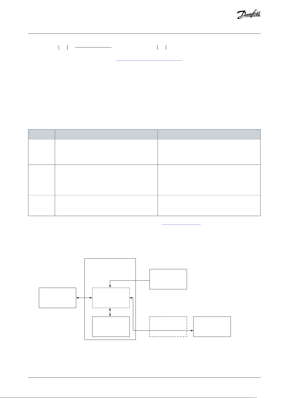
Location
Description
Checks and restrictions
OPTBL
OPTBM
OPTBN
The currently used parameter file is always saved on
the option board.
In the start-up of the option board, the option board
checks the parameter file to make sure that it is compatible. The option board always checks a new parameter file.
Control
board of the
AC drive
The currently used parameter file is uploaded to the
control board during start-up and after each change in
the parameter file. The parameter file is not stored permanently. To store the parameter file permanently in
the control board as a backup, use the control panel.
The control board checks the CRC of the uploaded or
stored parameter file to make sure that it is correct, but
does not check the compatibility of the parameter values.
PC
The parameter files should be stored on the PC and in
the version control or another system that is used to
handle the configurations used on the field.
VACON® Safe creates unverified parameter files and
stores verified parameter files "as is" without modifications to the safety critical and CRC protected area.
Advanced
safety option
board
Control panel
PC tool PC
Parameter file
Control Board
Location select
Save/Restore
Control board
back-up
e30bi375.10
VACON® NXP Advanced Safety Options
Operating Guide
Estimatedspeed rpm =
See the parameters related to estimated speed in 8.1.3 Speed Measurement Parameters.
GearRatioMultiplier
GearRatioDivider
×externalsensorspeed rpm
Overview of the System
3.6.10 Estimated Speed and External Accelerative Forces
If estimated speed is used in systems where the safe state is not the STO function alone, analyze the consequences on system level.
As estimated speed is not calculated when the AC drive is not in RUN state, the safety system depends on the external speed sensor.
During a standstill, only a single channel speed estimation is available. When external forces can cause acceleration and torque to
the motor and make the motor rotate, a mechanical brake must keep the motor shaft stationary.
3.7 Storage of Parameters
It is possible to store the parameters of the Advanced safety option board as a backup in other locations. The different backup locations are handled in the control board of the AC drive. Use the control panel of the AC drive to control the parameter backup.
Table 15: Parameter Storing Locations
For more information on the PC tool VACON® Safe or the parameter file, see 5.2 The Parameter File.
The handling of the parameter file backup on the control board is not a safety critical feature, and it is the responsibility of the
operator to use the correct parameters for the Advanced safety option board. A verified parameter file that is read from a backup to
the option board will be accepted and taken into use. If the parameter file does not correspond to the actual configuration, for
example, if it has a different encoder parameterized than what is supported by the used encoder interface board, the option board
does not allow the STO function to be deactivated.
Illustration 17: The Backup Locations of the Parameter File and their Control
AQ319736045637en-000101 / DPD01798 | 43Danfoss A/S © 2021.06
Page 44

Component
Version
Comment
The control board of VACON® NXP AC drive
Hardware: VB00761 B (141L8026) or newer
Software: NXP00002V198 or newer
The STO and ATEX option board (OPTAF)
Hardware: VB00328 E (141L7786) or newer
Check the safety levels of STO in the
product manual.
VACON® NXP Advanced Safety Options
Operating Guide
Overview of the System
N O T I C E
Only compatible parameter files are taken into use on the option board. If the data in the backup location is faulty and sent to the
option board, the option board detects the faultiness. The STO function stays active until a valid parameter file is provided.
3.7.1 Storing a Parameter File Backup
Use these instructions to store a parameter file backup from the Advanced Safety Option.
Procedure
1.
Find parameter P7.4.1.1.3 Save Backup To under the menu group G7.4.1.1 Config Settings.
2.
Select a backup location with parameter P7.4.1.1.3.
3.
Make sure that the parameter file backup was stored successfully.
a.
Make sure that the parameter file is also stored on the PC.
b.
Do factory reset for the Advanced safety option board.
c.
Do a parameter restore from the backup location.
3.7.2 Restoring a Parameter File from Backup
Use these instructions to restore a parameter file from a backup into Advanced Safety Option.
N O T I C E
When the parameter file is restored from backup, the passwords are reset to the default.
Procedure
1.
Find parameter P7.4.1.1.4 Load Backup From under the menu group G7.4.1.1 Config Settings.
2.
Select a backup location with parameter P7.4.1.1.4.
3.
Make sure that the restored parameter file is accepted by the Advanced safety option board.
4.
Make sure that the restored parameter file is the correct file.
a.
Load and view the parameter file on VACON® Safe.
b.
Check the parameter file CRC on the control panel.
c.
Check the used safety functions on the control panel.
d.
Check the parameter file creator and date on the control panel.
5.
Set the passwords to the intended values if necessary.
3.8 Advanced Safety Options with the NXP Drive
3.8.1 Requirements
To use the Advanced safety option board with the VACON® NXP AC drive, obey these requirements.
Table 16: Required Drive Component Versions
When a safe fieldbus is used, see also 7.1.1 Introduction to PROFIsafe for the fieldbus related requirements.
AQ319736045637en-000101 / DPD0179844 | Danfoss A/S © 2021.06
Page 45

PC tool
Version
Comment
NCDrive
2.0.29 or newer
Older versions than this can be used, but they do not show correctly the details of safety
related faults.
VACON® Loader
1.1.12.0 or newer
The tool is used to update the option board firmware.
VACON® Safe
1.0.2.0 or newer
The tool is used to parameterize and monitor the option board. See 5.1 Functions of the
VACON Safe Tool.
Drive application
- Execution of ramp stops
- Realisation of speed limit
- Process-specific actions
Control board firmware
- Communication with the option board
- Basic handling of faults and warnings
Advanced safety option board
- Handling of safe I/O and safe fieldbus
- Monitoring of safety functions
e30bi376.10
VACON® NXP Advanced Safety Options
Operating Guide
Table 17: The PC Tools that Can Be Used with the Option Board
Overview of the System
3.8.2 Compatibility with Drive Applications
The safety monitoring in the Advanced safety option board is independent of the drive application and of the methods used to
control the AC drive to fulfill the monitored limits. The monitoring is always executed the same way. Violations of safety limits result
in the set responses in the option board.
The option board can be used with any drive application. Older drive applications do not monitor or react to the safety system data.
When a such drive application is used, the AC drive must be monitored and controlled by external systems for the AC drive to operate within the limits set by the safety functions.
For example, the drive application can ramp down and limit the speed to a safe value when the Safe Limited Speed (SLS) function is
activated. Refer to the VACON® NX All-in-One Application Manual for more information.
N O T I C E
It is possible to use any drive application with the Advanced safety option board, but some applications cannot operate correctly
with the option board added to the system. In such cases, update the application.
The drive applications that are aware of the Advanced safety option board and able to use the related data can be used. A such
drive application can keep the AC drive within the limits set by the safety functions.
Illustration 18: Basic Tasks of the Option Board and the Control Board Firmware, and the Optional Tasks of the Drive Application
3.8.3 Option Board Menu on the Control Panel
When the Advanced safety option is used, use menu M7 Expander boards on the control panel of the drive to control the option
board and to read status data. It is possible to reset the option board passwords, do a factory reset, and control of the parameter file
backup. The status data includes the identification data for the parameter file, certain parameter values of the parameter file, and
the run-time monitoring data.
The option board menu structure can be seen in Illustration 19, and all the values are described in the tables below. The figure and
tables are for installation in slot D.For other slots the indexes are different. For example, G7.4.1 Parameters is G7.3.1 Parameters in
slot C.
AQ319736045637en-000101 / DPD01798 | 45Danfoss A/S © 2021.06
Page 46

M7 Expander boards
G7.4 OPTBL/OPTBM/OPTBN
G7.4.1 Parameters
G7.4.2 Monitor
G7.4.1.1 Config Settings
G7.4.2.1 Safety Functions
G7.4.2.2 Digital I/O
G7.4.2.3 Encoder
G7.4.2.4 PROFIsafe
G7.4.2.5 File Info
G7.4.2.6 Diagnostics
G7.4.1.2 Fault Settings
G7.4.1.3 Encoder
e30bi377.10
Index
Parameter
Min
Max
Unit
Default
ID
Description
P7.4.1.1.1
Password Reset
01–0–
0 = No action
1 = Reset
P7.4.1.1.2
Factory Reset
01–0–
0 = No action
1 = Reset
P7.4.1.1.3
Save Backup To
01–0–
0 = No action
1 = Control unit
2 = Keypad
(1)
P7.4.1.1.4
Load Backup From
01–0–
0 = No action
1 = Control unit
2 = Keypad
(1)
Index
Parameter
Min
Max
Unit
Default
ID
Description
P7.4.1.2.1
SafetySystem flt
02–0–
Selects the control board firmware response for fault code 20.
0 = "Default", F20 activated as fault or warning depending on the
case (application may decrease the reporting level, e.g. fault -> warning)
1 = "Warning", F20 activated as alarm
VACON® NXP Advanced Safety Options
Operating Guide
Overview of the System
Illustration 19: The Menu Structure of the Menus Related to the Advanced Safety Option Board
Table 18: Config Settings Group (G7.4.1.1)
1
Back-up to keypad requires a newer keypad unit with extended storage capability.
Table 19: Fault Settings (G7.4.1.2)
AQ319736045637en-000101 / DPD0179846 | Danfoss A/S © 2021.06
Page 47

Index
Parameter
Min
Max
Unit
Default
ID
Description
2 = "No Action", F20 not activated
P7.4.1.2.2
SafeF indication
02–0–
Selects the control board firmware response to safety function status
changes.
0 = "Default", F46/F47/F48 activated as alarm (application may decrease the reporting level, e.g. warning -> no action)
1 = "Violat only", F48 activated as alarm, F46/F47 not activated
2 = "No Action", F46/F47/F48 not activated
Index
Parameter
Min
Max
Unit
Default
ID
Description
P7.4.1.3.1
(1)
Reading Rate
04–1–
Time used to calculate actual speed value. Note: Use value 1 in
closed loop mode.
0 = No
1 = 1 ms
2 = 5 ms
3 = 10 ms
4 = 50 ms
Index
Parameter
Min
Max
Unit
Default
ID
Description
V7.4.2.1.1
STO––––
–
Shows the status of the safety function.
Not in use = The function is not taken into use in the parameter file.
Inactive = The safety function is not requested.
Requested = The safety function is requested.
Active = The safety function is active. (The signal xxx Active is "1".)
Reached = The safety function is reached. (The signal xxx Reached is "1".)
V7.4.2.1.2
SS1–––––V7.4.2.1.3
SS2–––––V7.4.2.1.4
SQS–––––V7.4.2.1.5
SSR–––––V7.4.2.1.6
SLS 1–––––V7.4.2.1.7
SLS 2–––––V7.4.2.1.8
SLS 3–––––V7.4.2.1.11
SSM–––––V7.4.2.1.12
SMS–––––V7.4.2.1.14
SOS–––––V7.4.2.1.15
SBC––––
–
VACON® NXP Advanced Safety Options
Operating Guide
Table 20: Encoder (G7.4.1.3)
Overview of the System
1
The menu group is accessible only when the Advanced safety option board is installed in slot C.
Table 21: Safety Functions Group (G7.4.2.1)
AQ319736045637en-000101 / DPD01798 | 47Danfoss A/S © 2021.06
Page 48

•
•
•••
•
•
•
•
Index
Parameter
Min
Max
Unit
Default
ID
Description
V7.4.2.2.1
DI1
DI2
DI3
DI4
–––––
Shows the logical value of the option board digital input. Updated
only for inputs that have safety functions assigned.
0 = The input is inactive
1 = The input is active
- = The input is not used
V7.4.2.2.2
DO1
DO2
–––––
Shows the logical value of the option board digital output.
0 = The output is inactive
1 = The output is active
- = The output is not used
Index
Parameter
Min
Max
Unit
Default
ID
Description
V7.4.2.3.1
Encoder
Type
–––––
Shows the encoder type specified in the parameter file. Values:
None
Increm. TTL
Increm. HTL
SinCos
V7.4.2.3.2
Estimated
Speed
–––––
Shows whether estimated speed is used in the parameter file. Values:
Not in us
In use
V7.4.2.3.3
Proximity
Sensor
–––––
Shows the number of used proximity sensors in use. Values:
None
1
2
V7.4.2.3.4
Encoder
Speed
––rpm––
Shows the average speed measured by the option board (encoder
and proximity sensors)
V7.4.2.3.5
Encoder
Freq
––Hz––
Shows the speed of the motor based on the encoder data.
VACON® NXP Advanced Safety Options
Operating Guide
Table 22: Digital I/O Group (G7.4.2.2)
Table 23: Encoder Group (G7.4.2.3)
Overview of the System
AQ319736045637en-000101 / DPD0179848 | Danfoss A/S © 2021.06
Page 49

•
•
•
Index
Parameter
Min
Max
Unit
Default
ID
Description
V7.4.2.4.1
Safety Telegram
–––––
Shows the number of the used telegram. Values:
ST 30
ST 31
ST 58000
V7.4.2.4.2
F-Par SRC Addr
–––––
Shows the value of F Source Address
V7.4.2.4.3
F-Par DEST Addr
–––––
Shows the value of F Destination Address
V7.4.2.4.4
F-Par WD Time
–––––
Shows the value of F WD Time
Index
Parameter
Min
Max
Unit
Default
ID
Description
V7.4.2.5.1
File Name
–––––
Shows the first 12 characters of parameter File name
V7.4.2.5.2
File Creator
–––––
Shows the first 12 characters of parameter File creator
V7.4.2.5.3
Company Name
–––––
Shows the first 12 characters of parameter Company (Parameter file)
V7.4.2.5.4
CRC–––––Shows the CRC of the used parameter file in hex format
V7.4.2.5.5
CRC integer
–––––
Shows the CRC of the used parameter file in decimal integer
format
Index
Parameter
Min
Max
Unit
Default
ID
Description
V7.4.2.6.1
Last Error Code
–––––
Shows the number of the last fault of the Advanced safety option board in hex format.
V7.4.2.6.2
SW Version
–––––
Shows the software version of the Advanced safety option
board.
V7.4.2.6.3
HW Version
–––––
Shows the hardware version of the Advanced safety option
board.
V7.4.2.6.4
FPGA Version
–––––
Shows the FPGA version of the encoder interface board on the
Advanced safety option board.
VACON® NXP Advanced Safety Options
Operating Guide
Table 24: PROFIsafe Group (G7.4.2.4)
Table 25: File Info Group (G7.4.2.5)
Overview of the System
Table 26: Diagnostics Group (G7.4.2.6)
3.8.4 Fault Types
The Advanced safety option board has different fault types: critical fault, resettable fault, violation, and warning. The fault types of
the Advanced safety option board are not the same as the fault types of the AC drive. For more details on faults, see 12.1 Presenta-
tion of Faults on the Control Board.
AQ319736045637en-000101 / DPD01798 | 49Danfoss A/S © 2021.06
Page 50

Fault type
of the option board
Possible cause
Correction
Fault
type of
the AC
drive
Response of the option
board
Critical
Fault
Internal broken hardware, incorrect
configuration, temporary malfunction detected by the diagnostics.
Attempt to fix the issue. Reboot
of the AC drive.
Fault
The STO function becomes
active, all outputs are inactive.
Resettable
Fault
External broken hardware, incorrect
configuration, temporary malfunction detected by the diagnostics.
Attempt to fix the issue. Cleared
with the reset signal. See 6.1.6
Reset of a Safety Function.
Fault
The STO+SBC function becomes active, see 6.2.2.3
The STO Function Used
with the SBC Function.
Violation
Violation of a monitoring limit in an
active safety function.
Cleared with the reset signal. See
chapters 6.1.4 Violation of a Safe-
ty Function and 6.1.6 Reset of a
Safety Function.
Warning
Safe monitoring functions:
the SQS function.
Safe stopping functions:
the STO+SBC function.
Warning
An event that does not affect the
operation, but is shown for information.
Does not require clearing. /
Cleared with the reset signal.
Warning
No response.
VACON® NXP Advanced Safety Options
Operating Guide
Table 27: Fault types of the Advanced safety option board
Overview of the System
Failures that are detected by the internal diagnostics of the option board trigger a fault. The faults can be resettable or critical.
Resettable faults are informed to the control board of the AC drive and reported on the fault log of the AC drive. They can be cleared
by a reset signal. See 6.1.6 Reset of a Safety Function.
Critical faults of the option board cause the option board to deactivate its outputs and communication to other systems. This means
that both the channels of the two-channel outputs are in the deactivated state. The safe fieldbus communication is also stopped. To
other systems, the situation looks as if the option board is not turned on or the cabling is faulty. Take this into account when designing and implementing other systems.
If the fault that causes the critical fault does not have an effect on the communication between the option board and the control
board of the AC drive, this communication stays active. The fault data can be read from the fault log of the AC drive. If the fault is
related to the communication or otherwise prevents the option board from communicating with the control board, the communication stops. In this case, the fault data cannot be read from the fault log.
N O T I C E
If the option board starts after a reboot of the AC drive, it may be possible to read the fault data in the activity log of the Advanced safety option board. See 5.6.2 Activity Log.
AQ319736045637en-000101 / DPD0179850 | Danfoss A/S © 2021.06
Page 51
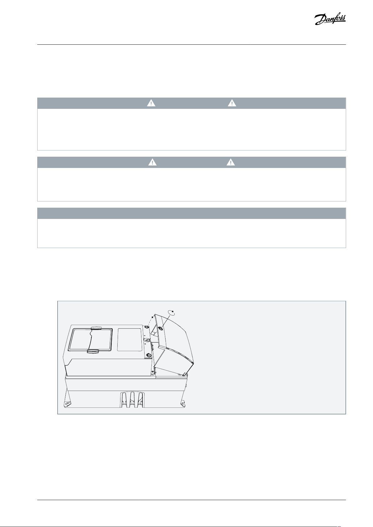
e30bi036.10
VACON® NXP Advanced Safety Options
Operating Guide
Installation
4 Installation
4.1 Installation Safety
Read these warnings before starting the installation of the option board.
W A R N I N G
SHOCK HAZARD FROM CONTROL TERMINALS
The control terminals can have a dangerous voltage also when the drive is disconnected from mains. A contact with this voltage
can lead to injury.
Make sure that there is no voltage in the control terminals before touching the control terminals.
-
C A U T I O N
DAMAGE TO OPTION BOARDS
Do not install, remove, or replace option boards on the drive when the power is on. Doing this can cause damage to the boards.
Switch off the AC drive before installing, removing, or replacing option boards on the drive.
-
N O T I C E
Measure or do a check of the encoder supply voltage of the encoder interface board before connecting a new encoder. It is possible that the encoder supply voltage was set to a higher voltage than what is supported by the new encoder. An incorrect encoder
supply voltage can damage the equipment.
4.2 Installing the Option Board
This topic gives instructions for installing the option board in VACON® NXP, FR4–FR9.
Procedure
1.
In FR5–FR9, open the cover of the AC drive.
2.
In FR4, remove the cable cover.
AQ319736045637en-000101 / DPD01798 | 51Danfoss A/S © 2021.06
Page 52

e30bi037.10
e30bi038.10
VACON® NXP Advanced Safety Options
Operating Guide
3.
Open the cover of the control unit.
Installation
4.
Install the option board into the slot C, D, or E on the control board of the AC drive. Make sure that the grounding plate fits
tightly in the clamp.
The board revision can affect the applicable installation slot.
5.
In IP21, cut free the opening on the cover of the AC drive for the fieldbus cable.
6.
Install the cables.
7.
Close the cover of the control unit and attach the cable cover.
AQ319736045637en-000101 / DPD0179852 | Danfoss A/S © 2021.06
Page 53

User level
Default password
Admin
admin
Service
service
VACON® NXP Advanced Safety Options
Operating Guide
VACON Safe Tool
5 VACON Safe Tool
5.1 Functions of the VACON Safe Tool
Use the VACON® Safe tool to parameterize the Advanced safety option board.
The functions of the VACON® Safe tool
•
Parameterization of the option board
•
Validation of the parameter file
•
Monitoring of the state of the option board and the safety functions
•
Setting the passwords for the option board
N O T I C E
VACON® Safe tool cannot be used for the general control and diagnostic of the AC drive. For those purposes, use NCDrive. The
option board firmware is updated with VACON® Loader.
5.2 The Parameter File
The configuration of the Advanced safety option board and the selected safety functions and their parameters are stored in a parameter file. The parameter files are created, viewed, and transferred between a PC and the option board with the VACON® Safe
tool.
A newly created parameter file on the PC is in state unverified. This means that the Advanced safety option board has not yet verified that the file is valid and can be taken into use. Once the option board has done the verification, the parameter file becomes
verified. The verification is done during the parameterization process.
If the verified parameter file is not modified, it can be saved to other Advanced safety option boards. The other option boards check
the parameter file to make sure that the content is not corrupted and that it matches the option board configuration, for example,
the encoder type.
The verification of a parameter file means that it can be taken into use, but the option board cannot determine if the parameter
values are correct for the process where the option board is used. After the verified parameter file is saved to the option board, test
the whole safety system to make sure that all safety subsystems operate correctly together. Test also that the safety functions of the
Advanced safety option board are correctly set for the process. After the testing, the parameter file can be updated to indicate that
it has been tested with the rest of the system.
After testing, the parameter file is validated. Validated parameter files can be saved to other Advanced safety option boards, like
verified parameter files, but the validation is cleared in the process. The report from commissioning should be included in the documentation and in the process of certifying the whole system.
5.3 User Levels and Password Management
To protect the parameters of the option board from accidental modifications, the option board has a two-level password system.
The admin and service level passwords have different rights for modifying the parameters of the option board.
A password is required in actions that write data on the option board. Reading actions are not password-protected. The PC tool asks
for the password when you try to start an action that requires a password. The default passwords are listed in the table below.
Table 28: Default Passwords
Actions that are available with the service level password
•
Validation of the parameter file
•
Saving the verified parameter file to the option board
Actions that are available with the admin level password
AQ319736045637en-000101 / DPD01798 | 53Danfoss A/S © 2021.06
Page 54

VACON® NXP Advanced Safety Options
Operating Guide
•
Validation of the parameter file
•
Saving the verified parameter file to the option board
•
Saving a new, unverified parameter file to the option board
•
Changing the admin and service level passwords
Actions that are available without a password
•
Reading the verified parameter file from the option board
•
Online monitoring of the option board
VACON Safe Tool
N O T I C E
If the passwords are forgotten, they can be reset from the control panel menu of the AC drive. This operation is not passwordprotected. The controlling of password reset must be done with other means.
5.4 Setting the Parameters
The parameterization process of the Advanced safety option board has 4 steps.
Procedure
1.
To select the desired safety functions and features, go to "Select functions" in the PC tool.
A short description is visible for every available option. For information on the safety functions, see chapter Safety Functions.
2.
Go to "Adjust parameters" in the PC tool.
All selected safety functions and features must be parameterized. See chapter Parameter List for information on the parameters.
When all safety functions and features have been parameterized, it is possible to save the parameter file to the option
board. The option board checks the compatibility of the parameter file. Only valid parameter files are accepted. VACON
Safe also limits the parameterization, so that invalid combinations are not sent to the option board.
N O T I C E
It is possible to save the current parameterization as a draft on the PC.
N O T I C E
Saving a new parameter file to the option board requires the admin level password.
3.
Verify the transfer of parameters to the option board. Go to "Verify and Approve".
The verifying view offers automated checks.
Accepting the parameters takes them into use in the option board. The parameter file is verified but not validated, that is,
it is not tested with the rest of the system.
The parameter file is marked as verified by the option board. A verified parameter file can be loaded from the op-
tion board and stored on the PC.
®
AQ319736045637en-000101 / DPD0179854 | Danfoss A/S © 2021.06
Page 55

Operator actions Advanced safety option board
actions
Initial parameterization
- Parameterization of
speed measurement
- Parameterization of
safe fieldbus
- Parameterization of
safety functions
Verification of parameters
- Comparison of sent and
readback values
- Approval of parameters
Finalisation
- Storing of the final
parameter file
- Documentation of
parameterization
Parameter file check
- Compatibility check
of parameters
Parameter file verification
- Adding verification
confirmation
- Calculation of final CRC
- Parameter file taken into
use
- Parameter file with
validation information
stored
PC
Advanced
safety
option
board
Send parameter file to drive
Parameter file readback for verification
Operator approval
Upload parameter file
Commissioning & testing of the safety system
PC
PC
Advanced
safety
option
board
Validation of parameters
- Adding validation
information
PC
Send validation information
Advanced
safety
option
board
e30bi378.10
VACON® NXP Advanced Safety Options
Operating Guide
4. Validate the parameter file by going to "Validate".
VACON Safe Tool
Illustration 20: The Process of Creating a New Parameter File
AQ319736045637en-000101 / DPD01798 | 55Danfoss A/S © 2021.06
Page 56

VACON® NXP Advanced Safety Options
Operating Guide
VACON Safe Tool
5.5 Saving a Verified Parameter File to the Option Board
A verified parameter file can be saved to the option board without executing the whole parameterization process. Saving a verified
parameter file can be done with the service level password. Modifications to a verified parameter file invalidate the verification and
the verification must be done again.
Procedure
1.
Open the verified parameter file. Make sure that also the PC tool confirms that it is verified.
2.
Check the parameters in the opened file. For example:
a.
Make sure that the I/O assignments match the wiring.
b.
Make sure that the correct safety functions are parameterized.
c.
Read the parameter file comment.
3.
Press "Save" to begin the saving process.
4.
Select an AC drive and connect to it.
5.
Save the parameter file and start testing the system.
5.6 Online Monitoring
5.6.1 Viewing the State of the Option Board
In the online monitoring mode, VACON® Safe reads the states and values of various signals of the Advanced safety option board
from the AC drive. These signals can be used to monitor the status and execution of the safety features of the AC drive.
The data available for monitoring:
•
States of the safety functions
•
States of the digital I/O
•
Speed values (estimated speed, the measured speed value of the external speed sensor)
•
Safe fieldbus status
N O T I C E
Online monitoring values are periodically read from the AC drive and the actual values can change between the readings.
5.6.2 Activity Log
The Advanced safety option board logs the events that occur during its operation. This log can be read from the option board and
viewed on the PC tool. Some of the data included in the log is also available when the state of the option board is viewed. The
activity log can be used when it is necessary to analyze the behavior of the option board during a time when the PC tool was not
connected to the option board. The log can be saved to the PC for further use.
The activity log contains
•
A timestamp that is synchronized to the AC drive operating time
•
Request signals for safety functions
•
Active and Reached signals for safety functions
Acknowledgment and Reset signals and their source
•
•
Information on the faults that occurred in the option board
The activity log logs the states of the signals when a change occurs in them. The length of the activity log is limited. Depending on
the used safety functions and the frequency of changes in the safety functions, the log may show only a short time. When there is a
situation that requires analysis, read the log as soon as possible to prevent new events from overwriting the critical parts.
The log is not lost when you do power-down to the AC drive.
AQ319736045637en-000101 / DPD0179856 | Danfoss A/S © 2021.06
Page 57

Safe monitoring functions
Safety function
request
Acknowledgement
Safety function
request
Acknowledgement
Limit violation
Active, ReachedActive, Reached
Reset
Limit violation
SLS
SS1
SS2
SQS
SOS SBC
STO
SSR
SMS
SSM
Safe stopping functions
e30bi365.10
VACON® NXP Advanced Safety Options
Operating Guide
Safety Functions
6 Safety Functions
6.1 General Information
6.1.1 The Different Safety Functions
The safety functions of the Advanced safety option board fulfill the corresponding requirements of the standard EN IEC 61800-5-2.
The standard EN IEC 61800-5-2 does not define the SQS safety function, but the function can be parameterized to behave like
STO(+SBC), SS1 or SS2. These functions fulfill the requirements of the standard.
The safety functions are divided into two categories: the safe stopping functions and the safe monitoring functions. The safe stop-
ping functions start and monitor the stopping of the motor, the safe monitoring functions monitor the speed, the position, or the
acceleration of the motor.
The safe stopping functions
•
the STO function
•
the SBC function
•
the SS1 function
•
the SS2 function
•
the SOS function
•
the SQS function
The safe monitoring functions
•
the SLS function
•
the SMS function
•
the SSR function
•
the SSM function
The SQS function can be used in STO, SS1 or SS2 modes. In this manual, these modes are referred to as SQS-STO, SQS-SS1, and SQSSS2.
Illustration 21: The Simplified Relations Between the Safety Functions
6.1.2 Safety Function States
The safety functions can be in three different states: inactive, active, and reached. The safety functions that are not requested or
have been acknowledged after their execution are inactive. Inactive safety functions are not executed and they do not do any monitoring. The states active and reached are shown with signals.
An inactive safety function becomes active when it receives a request. An active safe stopping function becomes reached when the
function is completed. An active safe monitoring function becomes reached when the monitored values are within the monitoring
limits.
AQ319736045637en-000101 / DPD01798 | 57Danfoss A/S © 2021.06
Page 58

VACON® NXP Advanced Safety Options
Operating Guide
Active and reached functions can have their monitoring limits violated.
When the STO function is active in the option board, for example because of a violation or a fault, all active safety functions stop the
monitoring of their limits. The functions stay active until they are acknowledged. The SSM function is an exception. It continues to
monitor even during standstill of the motor and violations of other safety functions.
Safety Functions
6.1.3 Activation of a Safety Function
Most safety functions can be activated with an external request from a safe digital input or a safe fieldbus. Both methods can be
used at the same time. When the two methods are used, a request from one source is sufficient to activate the safety function.
When a safety function becomes active, it gives an Active signal. Many functions can be active at the same time, but this does not
apply to all functions. Any combination of safe monitoring functions can be active at the same time, but for the safe stopping functions there are limitations because of their set priorities.
These safety functions can be activated with an external request from a digital input or a safe fieldbus: STO(+SBC), SS1, SS2, SQS,
SSR, SLS, SSM, and SMS.
The safety functions that cannot be activated with an external request are SBC and SOS. They are always activated by other safety
functions. The safety function STO activates SBC. The safety functions SS2 and SQS-SS2 activate SOS.
Some safety functions can also become active without an external request. The SQS function can become active as a violation response, the SSM function when always active, and the STO function as a violation response of safe stopping functions.
In some special conditions, a function cannot become active even if there is a request. These conditions include a request for a
lower priority function, an active violation or fault in the Advanced safety option board, and the active STO safety function. When
the Advanced safety option board is in the STO state, for example, because of a STO request, it is not necessary to activate safety
functions.
N O T I C E
Most safety functions do not become active or start operating if the drive is in the STO state. If there is a request, they become
active when the drive leaves the STO state.
In this manual, the external request signal has the format "[Safety Function Name] Request", for example "SMS Request".
6.1.4 Violation of a Safety Function
It is possible that violations occur in the monitoring. Causes for violations are, for example, the speed exceeding the monitored
speed limit, the speed not following the monitored ramp, or an operation exceeding the set time limit.
There are two different violation responses:
•
the STO (+SBC) function
•
the SQS function
N O T I C E
NO AUTOMATIC RAMP WITH SQS FUNCTION
When the SQS safety function is used, the Advanced safety option board does not execute any ramps on its own. Make sure that
the system reacts to violation situations in an acceptable way.
Execute a ramp stop by a drive application with safety support. See 13.3 SS1 Used with STO(+SBC).
-
Execute a ramp stop by a drive application without safety support by triggering a stop command externally.
-
Execute a ramp stop by a process control system. See 13.4 SS1 Without a Direct Support of the Drive Application and 13.6
-
SLS without a Direct Support of the Drive Application.
For safe stopping functions, the response to a violation is the STO (+SBC) function. For safe monitoring functions excluding SSM, the
response to a violation is the SQS function.
With the SSM function, there is no response to a violation. Instead, external systems are notified of the violation by a digital output
or a fieldbus.
To make a safety function recover from a violation, use a reset signal. See 6.1.6 Reset of a Safety Function.
AQ319736045637en-000101 / DPD0179858 | Danfoss A/S © 2021.06
Page 59

VACON® NXP Advanced Safety Options
Operating Guide
Safety Functions
6.1.5 Acknowledgment of a Safety Function
6.1.5.1 Acknowledgment of a Safety Function
The acknowledgment signal is used to deactivate a safety function that has been set to require a manual acknowledgment after the
safety function request has ended. The acknowledgment mode can be set as automatic or manual.
In the automatic mode, the acknowledgment is tied to the deactivation of the safety function request. In the manual mode, a separate acknowledgment signal from a digital input, the drive control board, or a fieldbus is necessary.
The selection between automatic and manual acknowledgment is made with a parameter and separately for each function. It is
possible to use functions with different acknowledgment settings at the same time.
A function can be acknowledged when these conditions apply:
•
There is no request signal.
When executed as a violation response, the SQS safety function may not be acknowledged separately. It is acknowledged as a part
of the safety function reset. See 6.1.6 Reset of a Safety Function.
If a function is set to have automatic acknowledgment, the function is deactivated when its request is deactivated.
N O T I C E
A higher priority safe stopping function can interrupt a lower priority safe stopping function before it is reached.
The manual acknowledgment signal has three allowed sources:
•
A safe digital input
A safe fieldbus
•
A not safe control board of the AC drive
•
The sources of the acknowledgment signal are equal. A manual acknowledgment signal from any of them is permitted to stop a
safety function.
The acknowledgment signal from the control board of the drive is sent when a fault reset command (drive input, fieldbus, drive
application, or drive control panel) is sent to the drive. You can disable the acknowledgment signal from the control board during
parameterization.
N O T I C E
When a safety function is requested by both a digital input and a fieldbus, both of them must deactivate the request before the
function can be acknowledged. When the last request is deactivated, the automatic acknowledgment signal becomes active, and
the manual acknowledgment signal becomes acceptable.
AQ319736045637en-000101 / DPD01798 | 59Danfoss A/S © 2021.06
Page 60

A B
Logical level
SS2 Request
SS2 Active
SOS Reached
SS2 Reached
Acknowledgement
t
t
t
t
t
e30bi358.10
A
The manual acknowledgment is rejected because the safe stopping function is requested
B
After the safety functions are not requested, the manual acknowledgment is accepted.
VACON® NXP Advanced Safety Options
Operating Guide
Safety Functions
Illustration 22: The Deactivation of the SS2 Request Before the Function is Reached. Acknowledgment: Manual.
AQ319736045637en-000101 / DPD0179860 | Danfoss A/S © 2021.06
Page 61

A
Logical level
SS2 Request
SS2 Active
SOS Reached
SS2 Reached
Acknowledgement
t
t
t
t
t
e30bi359.10
A
The automatic acknowledgment occurs when the SS2 request ends.
VACON® NXP Advanced Safety Options
Operating Guide
Safety Functions
Illustration 23: The Deactivation of the SS2 Request Before the Function is Reached. Acknowledgment: Automatic.
When there are safety functions that can be acknowledged by manual acknowledgment and safety functions that cannot (if, for
example, they are requested), a manual acknowledgment signal deactivates the functions that can be acknowledged. Functions
that could not be acknowledged continue their execution normally.
AQ319736045637en-000101 / DPD01798 | 61Danfoss A/S © 2021.06
Page 62

Logical level
SSR Request
SSR Active
SSR Reached
SLS Request
Acknowledgement
t
t
SLS Active
SLS Reached
t
t
t
t
t
e30bi360.10
VACON® NXP Advanced Safety Options
Operating Guide
Safety Functions
Illustration 24: Acknowledging a safety function separately. The SLS function is acknowledged. The SSR function is not acknowledged because
it stays requested. SLS: manual acknowledgment, SSR: manual acknowledgment.
After safe stopping functions are acknowledged and the STO function is deactivated, the drive can start if it has an active run
request.
N O T I C E
The acknowledgment signal can also be used to control accidental starts of the drive. If the deactivation of the request of a safe
stopping function should not be able to allow the drive to start, use the manual acknowledgment. The drive can then start only
after a separate acknowledgment signal.
If a safe stopping function is used as an emergency stop according to the standard IEC-60204-1, the acknowledgment signal can be
used as the reset signal required by the standard. The reset signal of the Advanced safety option board does not correspond to the
emergency stop reset signal described in the standard.
In digital inputs, the acknowledgment signal is edge sensitive. The acknowledgment is done with inactive -> active transition (logical level). In safe fieldbuses, the acknowledgment signal is also edge sensitive, and it is done with a 0 -> 1 transition of the related
telegram bit.
AQ319736045637en-000101 / DPD0179862 | Danfoss A/S © 2021.06
Page 63

VACON® NXP Advanced Safety Options
Operating Guide
Safety Functions
N O T I C E
Acknowledgment and Reset can be assigned to the same digital input of the Advanced safety option board. Consider the behavior of the safety functions and the safety system carefully, if you decide to do that.
6.1.5.2 Start-up Acknowledgment
In addition to acknowledging safety functions, the acknowledgment signal can also be used to permit the Advanced safety option
board to release STO(+SBC) after start-up. This acknowledgment signal can be automatic or manual.
If automatic acknowledgment is used, STO(+SBC) is released after the Advanced safety option board has done the start-up and established communication to the drive control board and over safe fieldbus (when used). If manual start-up acknowledgment is
used, the STO(+SBC) is kept active until the acknowledgment signal is received.
6.1.6 Reset of a Safety Function
Violations of safety functions or faults of the Advanced safety option board cause the STO(+SBC) function to be activated. Use a
reset signal to deactivate the STO(+SBC) function, reset faults and return the system to normal operation. For the Advanced safety
option board, the reset signal is always an explicit signal from another system.
N O T I C E
If the SQS-SS2 function is used, a violation of a safe monitoring function can activate the SOS function. You can reset the SOS
function in the same way as the STO function.
The reset signal has three allowed sources:
•
A safe digital input
•
A safe fieldbus
•
A not safe control board of the AC drive
The sources of the reset signal are equal. A reset signal from any of them is permitted to reset violations of safety functions and
faults in the Advanced safety option board.
The reset signal from the control board of the drive is sent when a fault reset command (drive input, fieldbus, drive application, or
drive control panel) is sent to the drive. If a safe reset signal is required, disable the reset signal from the control board of the AC
drive in parameterization.
Different conditions apply for resetting the violations of safety functions and the faults of the Advanced safety option board.
To reset violations of safety functions or faults of the Advanced safety option board, these conditions apply:
•
STO(+SBC) or SOS is active (SOS in case of SQS-SS2)
•
The speed is below the monitoring limit of all requested safety functions
In digital inputs, the reset signal is edge sensitive. The reset is done with inactive -> active transition (logical level). A reset over a
safe fieldbus depends on the selected fieldbus. See 7.1.1 Introduction to PROFIsafe for information on the differences of the fieldbuses.
N O T I C E
After a violation or a fault, the reset signal behaves as an implicit acknowledgment signal for safety functions for which acknowledgment conditions apply when a reset signal is sent.
AQ319736045637en-000101 / DPD01798 | 63Danfoss A/S © 2021.06
Page 64

A B
Logical level
SSR Request
SSR Reached
SSR Active
SQS Active
t
t
t
t
SLS Request
SLS Reached
SLS Active
t
t
t
Reset
t
t
SQS Reached
e30bi361.10
A
A violation in the SLS function.
B
A reset signal resets the violation. The operation of the SSR and SLS functions continues.
VACON® NXP Advanced Safety Options
Operating Guide
Safety Functions
Illustration 25: Resetting a Safety Function Separately. SLS: Manual Acknowledgment.
Acknowledgment and Reset can be assigned to the same digital input of the Advanced safety option board. Consider the behavior of the safety functions and the safety system carefully, if you decide to do that.
N O T I C E
N O T I C E
Some faults of the Advanced safety option board can only be reset with a reboot of the drive. See chapter Fault Tracing for more
information.
There can be a delay between the reset signal and the removal of faults and warnings from the AC drive.
6.1.7 Ramps
The safety functions SS1, SS2, SQS, SSR, and SLS can monitor the ramping of the motor speed. The ramps are optional, and all safety
functions that provide ramp monitoring can be parameterized to not monitor them.
AQ319736045637en-000101 / DPD0179864 | Danfoss A/S © 2021.06
Page 65

A
C D
B
Rampx Speed
Rampx Dec Time Max
Nominal deceleration ramp
Rampx Dec Time Min
SS1 Dec Max
SS1 Dec Min
SS1 td1
Speed
Zero Speed
t
Speed
Scaled deceleration ramp
e30bi366.10
A
Start of the minimum deceleration ramp
B
Start of the maximum deceleration ramp
C
End of the minimum deceleration ramp
D
End of the maximum deceleration ramp
VACON® NXP Advanced Safety Options
Operating Guide
The monitored ramps are defined with two shared ramp definitions that the other safety functions than the SQS function can use to
calculate the actual ramps. The SQS function has its own ramp values. The ramp definition has a maximum and a minimum time
that is permitted for the ramping.
Safety Functions
N O T I C E
When a safety function uses a ramp, the related ramp must be defined. It is not necessary to parameterize both minimum and
maximum ramps if they are not necessary for the application.
Deceleration ramps are defined by a nominal speed value and two time values that represent the maximum and minimum time
that the ramping from the nominal speed is permitted to take. The actual monitored ramps are calculated when ramp monitoring
starts. The ramps are defined as slopes between the request moment and the parameterized times (SS1 used as an example).
SS1_Dec_Max s =
SS1_Dec_Min s =
where Speed[rpm] is the speed at the time of the calculation. SS1_Dec_Max and SS1_Dec_Min are the time from ramp start (points
A and B) to where speed should be zero (points C and D). Rampx_speed is the nominal speed for the used ramp set. See the figure
below. At any given point during the ramp monitoring, the actual value of monitoring is calculated from the slope connecting the
respective points. The area outside the permitted speed range during ramp monitoring is shaded.
Speed rpm × Rampx_Dec_Time_max s
Rampx_speed rpm
Speed rpm × (Rampx_Dec_Time_min s − SS1_td1 s )
Rampx_speed rpm
Use of ramp monitoring is not recommended when only proximity sensors are used as speed sensor.
N O T I C E
Illustration 26: Deceleration Ramp, the SS1 Function as an Example
Ramp monitoring does not continue in the safe speed range of the safe monitoring function. For example, for the SLS function, the
maximum ramp value is limited to the selected SLS limit. This can be noted, for example, with long SLS td2 delays. The minimum
ramp monitoring stops when the monitoring value would be below the selected SLS limit.
AQ319736045637en-000101 / DPD01798 | 65Danfoss A/S © 2021.06
Page 66

C
A
D
B
Speed
Nominal Acceleration Ramp
Scaled Acceleration Ramp
Rampx Speed
SSR Max Limit
SSR Min Limit
Speed
SSR td1
SSR Acc Min
SSR Acc Max
Rampx Acc Time Min
Rampx Acc Time Max
t
e30bi386.10
A
Start of the minimum acceleration ramp
B
Start of the maximum acceleration ramp
C
End of the minimum deceleration ramp
D
End of the maximum deceleration ramp
VACON® NXP Advanced Safety Options
Operating Guide
The acceleration ramps are valid only for the SSR function. The acceleration ramps are defined in the same way as deceleration
ramps. A nominal speed value (shared with the deceleration ramp) and two time values that represent the maximum and minimum
time that the ramping is permitted to take. The actual monitored ramps are calculated when ramp monitoring starts.
SSR_Acc_max s =
SSR_Acc_min s =
where Speed is the speed at the time of the calculation. SSR_Acc_Max and SSR_Acc_Min are the time from ramp start (A and B)
where speed should be at the monitored minimum limit speed (C and D). Rampx_speed is the nominal speed for the ramp set. At
any given point during the ramp monitoring the actual value of monitoring is calculated from the slope connecting the respective
points.
(SSR_Min_Limit rpm − Speed rpm ) ×Ramp_Acc_Time_Min s
Rampx_speed rpm
(SSR_Min_Limit rpm − Speed rpm ) ×(Ramp_Acc_Time_Min s − SSR_td1 s
Rampx_speed rpm
Safety Functions
Illustration 27: Acceleration Ramps, the SSR Function as an Example
The response to a ramp violation is the STO(+SBC) function for safe stopping functions, and the SQS function for safe monitoring
functions.
6.2 Safe Stopping Functions
6.2.1 Introduction to the Safe Stopping Functions
The safe stopping functions are used to start and monitor the stopping of the motor. The safe stopping functions do not take into
account the rotation direction of the motor when they are in the optional zero speed or the ramp monitoring mode. The SOS function is an exception, it takes into account the rotation direction of the motor.
The priority of the safe stopping functions from the highest to the lowest:
1. The STO function
2. The SQS function
N O T I C E
AQ319736045637en-000101 / DPD0179866 | Danfoss A/S © 2021.06
Page 67

Speed
Logical level
SS2 Reached
SS1 Active
SS2 Active
Zero speed
Speed
SS1 Reached
SS2 td1
t
t
t
t
t
SS1 td1
e30bi354.10
VACON® NXP Advanced Safety Options
Operating Guide
3. The SS1 function
4. The SS2 function
When a higher priority function is requested while a lower priority function is active, it interrupts the lower priority function and
becomes active. The higher priority function behaves as it is parameterized. The lower priority function stays active, but it stops
monitoring.
When a lower priority function is requested while a higher priority function is active, the lower priority function does not become
active.
Safety Functions
Illustration 28: The SS1 Function Interrupts the SS2 Function. The Signal SS2 Active Stays Active but the Operation Stops
If a higher priority function interrupts a lower priority function, both functions must be not requested for the STO(+SBC) or the SOS
function to be deactivated.
If the SS1 function is requested when the SOS function is active (if, for example, the SS2 function is reached), the SS1 function activates the STO function after SS1 td2, without ramp or time monitoring.
6.2.2 STO - Safe Torque Off and SBC - Safe Brake Control
6.2.2.1 Introduction to the STO and SBC Functions
The Safe Torque Off (STO) safety function allows the drive output to be disabled so that the drive cannot generate torque to the
motor shaft.
AQ319736045637en-000101 / DPD01798 | 67Danfoss A/S © 2021.06
Page 68

Speed
t
e30bi387.10
Speed
SBC
STO
SBC t1
t
e30bi388.10
VACON® NXP Advanced Safety Options
Operating Guide
The STO function can be used together with the Safe Brake Control (SBC) safety function. The SBC function provides a safe output
with which it is possible to control an external brake.
The STO function fulfills the stop category 0 of the standard IEC-60204-1.
For effects of the STO function on the AC drive, see the VACON® NX OPTAF STO Board Manual.
Things that can activate the STO(+SBC) function:
•
An external request
•
A violation of another safety function (as SQS or as a safe stopping function violation response)
•
A fault detected by the internal diagnostics of the Advanced safety option board
The parameters of the STO and SBC safety functions are described in
8.4 STO and SBC Parameters.
Safety Functions
6.2.2.2 The STO Function Used without the SBC Function
When there is an external request for the STO function, or a violation of another safe stopping function, the STO function is activated immediately.
Illustration 29: The STO Function
The STO output of the Advanced safety option board is connected to the STO option board that handles the operation of the STO
function in the drive. When the STO function is active, it disables the drive output. Then the drive cannot generate torque to the
motor shaft.
6.2.2.3 The STO Function Used with the SBC Function
When the STO function is used with the SBC function, the behavior of the STO output, the STO signals, the SBC output, and the SBC
signals depends on the values of the SBC parameters. The parameter SBC Order defines which safety function becomes active first.
The second safety function becomes active after the time that is set in SBC t1.
Illustration 30: STO Behaviour with SBC Order = SBC First
AQ319736045637en-000101 / DPD0179868 | Danfoss A/S © 2021.06
Page 69

Speed
STO
SBC
SBC t1
t
e30bi389.10
STO requested by
SBC Speed = 0
SBC Speed > Zero Speed
External request
STO at the request. SBC delayed by SBC t1 compared to STO.
Invalid configurations
The SS1 or SQS-SS1 safety
function
Time monitoring: STO after SQS t1 or SS1 t1.
Zero speed monitoring: STO when speed below zero speed and
SQS td2 or SS1 td2 expires.
SBC delayed by SBC t1 compared to STO.
Invalid configurations
Violation of SS1, SS2, or SQS or
resettable fault
STO at the fault moment. SBC delayed by SBC t1 compared to STO.
Invalid configurations
STO initiated by
SBC Speed = 0
SBC Speed > Zero Speed
External request
SBC at the request. STO delayed by SBC t1 compared to SBC.
SBC at the request, STO delayed by SBC t1 compared to SBC.
The SS1 or SQS-SS1 safety function
Time monitoring: SBC after SQS t1 or SS1 t1.
Zero speed monitoring: SBC when speed below
Zero Speed and SQS td2 or SS1 td2 expires.
STO always delayed by SBC t1 compared to SBC.
Time monitoring: SBC after SQS t1/SS1 t1 or
when speed below SBC Speed.
Zero speed monitoring: SBC when speed below
SBC Speed.
STO delayed by SBC t1 compared to SBC.
Violation of SS1, SS2, or
SQS or resettable fault
STO and SBC at the fault moment. SBC t1 not
used.
STO and SBC at the fault moment. SBC t1 not
used.
VACON® NXP Advanced Safety Options
Operating Guide
Illustration 31: STO Behaviour with SBC Order = STO First
Table 29: The Behavior of the STO and SBC Functions when SBC Order = STO First
Safety Functions
Table 30: The Behavior of the STO and SBC Functions when SBC Order = SBC First
After acknowledgment or reset, the STO and the SBC functions are deactivated at the same time. Other brake controlling systems
can be used to make sure that sufficient torque has been generated to the motor shaft before the brake is released.
6.2.2.4 The STO and SBC Signals
It is possible that the Active and Reached signals that are mentioned in this chapter are not always available in all interfaces.
N O T I C E
The availability of the signals over safe fieldbus depends on the fieldbus protocol that you use. Refer to chapter Safe fieldbuses
for more information.
AQ319736045637en-000101 / DPD01798 | 69Danfoss A/S © 2021.06
Page 70

•
•
•
•
•
•
•
•
•
•
•
•
•
•
•
•
•
Signal
Activation and deactivation of the signal
Description
STO Active
Activation:
STO safety function is requested externally or from another safety function. OR
Fault detected in the Advanced safety option board
Deactivation (manual acknowledgment):
Acknowledgment signal received
Deactivation (automatic acknowledgment):
STO request ends
Deactivation (fault situation):
Reset signal is given after a fault situation is cleared and reset conditions are valid
The signal indicates if STO function is being executed.
STO
Reached
This signal corresponds to the state of STO output on the Advanced safety option board. The
actual state of the output is reversed compared to the STO Reached signal. If STO Reached is
active, the STO output is inactive.
Activation:
Immediately with STO Active (SBC Order = STO first or SBC is not used, or fault situation) OR
After SBC t1 (SBC Order = SBC first)
Deactivation (manual acknowledgment):
Acknowledgment signal received when STO request has ended.
Deactivation (automatic acknowledgment):
STO request is deactivated.
Deactivation (fault situation)
Reset signal is given after a fault situation is cleared and reset conditions are valid.
The signal indicates if the STO
output is activated.
SBC
Reached
Signal corresponds to the state of SBC output on the Advanced safety option board. The actual
state of the output is reversed compared to the SBC Reached signal. If SBC Reached is active, the
SBC output is inactive.
Activation:
Immediately with STO_Active (SBC Order = SBC first) OR
After SBC t1 (SBC Order = STO first)
Deactivation (manual acknowledgment):
acknowledgment signal received when STO request has ended
Deactivation (automatic acknowledgment):
STO request is deactivated.
Deactivation (fault situation):
Reset signal is given after a fault situation is cleared and reset conditions valid
The signal indicates if the SBC
output is activated.
STO & SBC
reached
Activation:
When both SBC Reached and STO Reached are activated.
Deactivation:
When either SBC Reached or STO Reached is deactivated.
See STO and SBC signals above.
Combination of
STO and SBC
reached signals.
VACON® NXP Advanced Safety Options
Operating Guide
Table 31: The STO and SBC Signals
Safety Functions
AQ319736045637en-000101 / DPD0179870 | Danfoss A/S © 2021.06
Page 71
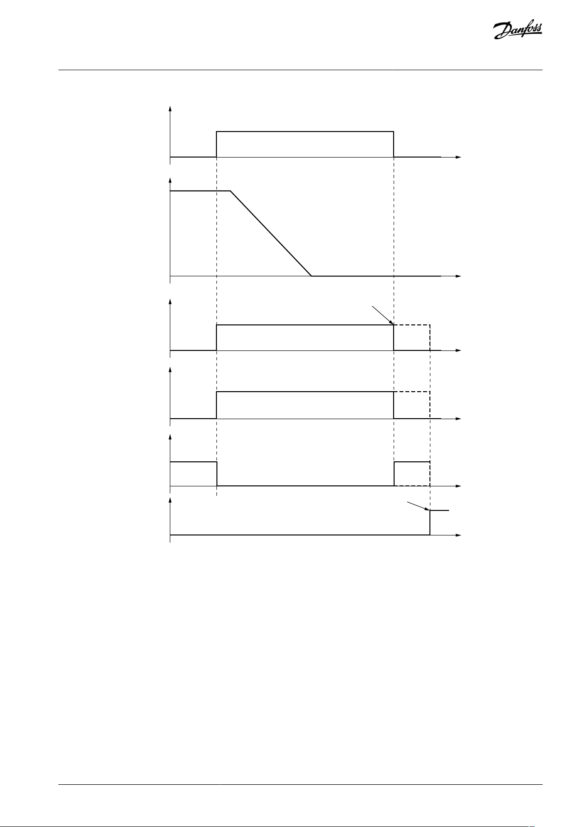
Speed
t
t
t
t
t
Logical level
Logical level
Automatic acknowledgement
Manual acknowledgement
STO Request
t
STO Active
STO Reached
STO Output
Acknowledgement
e30bi338.10
VACON® NXP Advanced Safety Options
Operating Guide
Safety Functions
Illustration 32: The STO Signals when the SBC Function is not Used
AQ319736045637en-000101 / DPD01798 | 71Danfoss A/S © 2021.06
Page 72

Speed
Logical level
Logical level
Automatic acknowledgement
Manual acknowledgement
STO Request
STO Active
STO Reached
SBC Reached
Acknowledgement
SBC t1
t
t
t
t
t
t
e30bi339.10
VACON® NXP Advanced Safety Options
Operating Guide
Safety Functions
Illustration 33: The STO and SBC Signals when the SBC Function is Used, SBC Order = STO First, and the STO Function is Requested
AQ319736045637en-000101 / DPD0179872 | Danfoss A/S © 2021.06
Page 73

Speed
Logical level
Logical level
Automatic acknowledgement
Manual acknowledgement
SS1 Request
STO Active
SBC Speed
Zero Speed
SBC Reached
STO Reached
Acknowledgement
SBC t1
SS1 td1
t
t
t
t
t
t
e30bi340.10
VACON® NXP Advanced Safety Options
Operating Guide
Safety Functions
Illustration 34: The STO and SBC Signals when the SBC Function is Used, and the SS1 Function is Requested. SBC Order = SBC First. The SS1
Signals are Omitted from the Figure.
6.2.3 SS1 - Safe Stop 1
6.2.3.1 Introduction to the SS1 Function
The Safe Stop 1 (SS1) safety function monitors the motor deceleration and activates the STO(+SBC) function. Select the activation
settings of the STO(+SBC) function with the SS1 parameters.
The SS1 function can operate in one of the three monitoring modes:
•
Time monitoring mode
•
Time + zero speed monitoring mode
•
Time + zero speed + ramp monitoring mode
The SS1 function can activate the STO function:
•
When an application-specific time delay has passed (Time monitoring).
•
When the speed reaches zero speed (Zero speed monitoring).
AQ319736045637en-000101 / DPD01798 | 73Danfoss A/S © 2021.06
Page 74

SS1 t1
t
Speed
STO + SBC
e30bi390.10
Zero speed /
SBC speed
SS1 t1
t
Speed
STO + SBC
SS1 td2
e30bi391.10
VACON® NXP Advanced Safety Options
Operating Guide
The STO function can also become active as a violation response, when the speed does not follow the set deceleration ramp (Ramp
monitoring).
The SS1 function fulfills the stop category 1 of the standard IEC-60204-1.
The parameters of the SS1 safety function are described in 8.5 SS1 Parameters.
Safety Functions
6.2.3.2 Time Monitoring
Illustration 35: The SS1 Function in the Time Monitoring Mode
The time monitoring mode is always used when SS1 is active. In the time monitoring mode, the STO function is activated when the
time indicated by parameter SS1 t1 has elapsed. The SS1 t1 timer starts when the SS1 function starts its operation.
If the SBC function is used and the value of the parameter SBC Speed is set to above zero, the STO(+SBC) becomes active after SS1
t1, or when the speed goes below SBC Speed, whichever is valid first.
6.2.3.3 Zero Speed Monitoring
Illustration 36: The SS1 Function in the Time + Zero Speed Monitoring Mode
AQ319736045637en-000101 / DPD0179874 | Danfoss A/S © 2021.06
Page 75

•
Zero speed /
SBC speed
SS1 t1
SS1 td1
t
Speed
STO +
SBC
SS1 td2
e30bi392.10
Signal
Activation and deactivation of the signal
Description
SS1 Active
Activation:
SS1 is requested and starts execution.
Deactivation (manual acknowledgment):
The signal indicates if SS1 function is being executed.
VACON® NXP Advanced Safety Options
Operating Guide
When zero speed monitoring is used, time monitoring is also used. Zero speed monitoring monitors if the motor stops. The stopping of the motor is determined by parameter Zero Speed. When zero speed monitoring is used, the speed going below the zero
speed starts a delay time set in SS1 td2 after which the SS1 function is reached. When the SS1 function is reached, the STO function
becomes active. The SS1 function must be reached before the time that is set in SS1 t1 elapses. If SS1 t1 elapses first, the STO function is activated as a violation response, not as a regular STO safety function.
If the SBC function is used, the moment when the brake output becomes active depends on the parameterization of the SBC function. See 6.2.2.3 The STO Function Used with the SBC Function.
Safety Functions
6.2.3.4 Ramp Monitoring
Illustration 37: The SS1 Function in the Time + Zero Speed + Ramp Monitoring Mode
When ramp monitoring is used, zero speed monitoring and time monitoring are also used. Ramp monitoring monitors that the
deceleration speed obeys the set deceleration ramp. Select the monitored ramp with parameter SS1 Ramp Monitoring. The ramp
can be static or dynamically selected by a digital input or a fieldbus. It is possible to monitor the minimum ramp, the maximum
ramp, or both these ramps.
The ramp monitoring starts after the time delay that is set with SS1 td1 has passed. SS1 td1 starts when the SS1 function starts its
operation. The ramp monitoring ends when the SS1 function is reached. If the speed does not obey the parameterized ramp during
the monitoring, the STO function becomes active as a violation response.
When using dynamic ramp from digital input or fieldbus, the monitored ramp is determined at the moment when the SS1 function
is requested. The changes that are made after this do not affect the operation of the function.
6.2.3.5 The SS1 Signals
It is possible that the Active and Reached signals that are mentioned in this chapter are not always available in all interfaces.
The availability of the signals over safe fieldbus depends on the used fieldbus protocol. Refer to chapter Safe fieldbuses for more
information.
Table 32: The SS1 Signals
N O T I C E
AQ319736045637en-000101 / DPD01798 | 75Danfoss A/S © 2021.06
Page 76

•
•
•
•
•
•
•
•
Signal
Activation and deactivation of the signal
Description
Acknowledgment signal received after SS1 is not requested.
Deactivation (automatic acknowledgment):
SS1 request ends.
Deactivation (SS1 violation situations):
Reset signal received after SS1 had detected a violation and SS1 has been acknowledged
(implicitly and explicitly).
SS1
Reached
Only activated when SS1 has not detected any violations.
Activation:
Time SS1_t1 elapses (only time monitoring used). OR
Speed is below zero speed for time SS1_td1 (zero speed monitoring used).
Deactivation (manual acknowledgment):
SS1 is acknowledged after being reached successfully.
Deactivation (automatic acknowledgment):
SS1 was reached successfully and SS1 request ends.
Deactivation (higher priority function is requested):
STO or SQS is requested.
The signal indicates if SS1 function has been
reached successfully.
Speed
Logical level
Logical level
SS1 Request
SS1 Reached
SS1 Active
Acknowledgement
SS1 t1
t
t
t
t
t
Automatic acknowledgement
Manual acknowledgement
e30bi335.10
VACON® NXP Advanced Safety Options
Operating Guide
Safety Functions
Illustration 38: The SS1 Signals in the Time Monitoring Mode
AQ319736045637en-000101 / DPD0179876 | Danfoss A/S © 2021.06
Page 77

Speed
Zero Speed
Logical level
Logical level
SS1 Request
SS1 Reached
SS1 Active
Acknowledgement
SS1 td2
t
t
t
t
t
Automatic acknowledgement
Manual acknowledgement
e30bi336.10
VACON® NXP Advanced Safety Options
Operating Guide
Safety Functions
Illustration 39: The SS1 Signals in the Zero Speed Monitoring Mode
AQ319736045637en-000101 / DPD01798 | 77Danfoss A/S © 2021.06
Page 78

Speed
Zero Speed
Violation
Logical level
Logical level
SS1 Request
STO Reached
SS1 Reached
Reset
SS1 t1
t
SS1 Active
t
t
t
t
t
e30bi337.10
VACON® NXP Advanced Safety Options
Operating Guide
Safety Functions
Illustration 40: The SS1 Signals in Zero Speed Monitoring Mode in a Violation Case. The STO Function without SBC.
6.2.4 SS2 - Safe Stop 2 and SOS - Safe Operating Stop
6.2.4.1 Introduction to the SS2 and SOS Functions
The Safe Stop 2 (SS2) safety function starts the motor deceleration and activates the SOS function.
The SS2 function can operate in one of the three monitoring modes:
•
Time monitoring mode
•
Time + zero speed monitoring mode
•
Time + zero speed + ramp monitoring mode
The SS2 function can activate the SOS function:
•
When an application-specific time delay has passed (Time monitoring)
•
When the speed reaches zero speed (Zero speed monitoring)
The violation response of the SS2 function is the STO(+SBC) function. During ramp down, it is possible to monitor the deceleration.
If there is a violation in the ramp monitoring of the SS2 function, or if zero speed is not reached, it activates the STO(+SBC) function
as a violation response.
The SOS safety function keeps the drive output active and monitors the positions of the motor shaft. A violation of the position
monitoring of the SOS function activates the STO(+SBC) function.
The SS2 and SOS functions fulfill the stop category 2 of the standard IEC-60204-1.
The parameters of the SS2 and SOS safety functions are described in 8.6 SS2 and SOS Parameters.
N O T I C E
The SS2 safety function can be used only with Sin/Cos encoders.
AQ319736045637en-000101 / DPD0179878 | Danfoss A/S © 2021.06
Page 79

SOS
SS2 t1
t
Speed
0
SOS Revolution Limit
e30bi393.10
SOS Revolution Limit
SOS
SS2 t1
SS2 td2
t
Speed
Zero speed
e30bi394.10
VACON® NXP Advanced Safety Options
Operating Guide
Safety Functions
6.2.4.2 Time Monitoring
Illustration 41: The SS2 Function in the Time Monitoring Mode
The time monitoring mode is always used when SS2 is active. The SOS function becomes active when the time that is set with parameter SS2 t1 has passed. The SS2 t1 timer starts when the SS2 function starts its operation.
6.2.4.3 Zero Speed Monitoring
Illustration 42: The SS2 Function in the Zero Speed Monitoring Mode
When zero speed monitoring is used, time monitoring is also used. Zero speed monitoring monitors if the motor stops. The stopping of the motor is determined by parameter Zero Speed. When zero speed monitoring is used, the speed going below the zero
speed starts a delay time set in SS2 td2 after which the SS2 function is reached. When the SS2 function is reached, the SOS function
becomes active. The SS2 function must be reached before the time that is set in SS2 t1 elapses. If SS2 t1 elapses first, the STO(+SBC)
function is activated as a violation response.
AQ319736045637en-000101 / DPD01798 | 79Danfoss A/S © 2021.06
Page 80

SOS Revolution Limit
SOS
SS2 t1
SS2 td2SS2 td1
t
Speed
Zero speed
e30bi395.10
VACON® NXP Advanced Safety Options
Operating Guide
6.2.4.4 Ramp Monitoring
Safety Functions
Illustration 43: The SS2 Function in the Ramp Monitoring Mode
When ramp monitoring is used, zero speed monitoring and time monitoring are also used. Ramp monitoring monitors that the
deceleration speed obeys the set deceleration ramp. Select the monitored ramp with parameter SS2 Ramp Monitoring. The ramp
can be static or dynamically selected by a digital input or a fieldbus. It is possible to monitor the minimum ramp, the maximum
ramp, or both these ramps.
The ramp monitoring starts after the time delay that is set with SS2 td1 has passed. SS2 td1 starts when the SS2 function starts its
operation. The ramp monitoring ends when the SS2 function is reached. If the speed does not obey the parameterized ramp during
the monitoring, the STO(+SBC) function becomes active as a violation response.
When using dynamic ramp from digital input or fieldbus, the monitored ramp is determined at the moment when the function is
requested. The changes that are made after this do not affect the operation of the function.
6.2.4.5 The SOS Safety Function
When the SOS safety function is active, it monitors the rotation of the motor shaft. Use parameter SOS Revolution Limit to set the
allowed deviation from the position at the beginning of the monitoring. Exceeding the allowed deviation from the starting point
activates the STO(+SBC) function as a fault response.
The deviation that is set by SOS Revolution Limit applies to both the directions from the point at the beginning of the monitoring. It is possible that the shaft rotates to one direction almost the maximum deviation and then to the other direction almost
double the allowed deviation without violating the monitoring.
During parameterization, the compatibility of the value of SOS Revolution Limit is checked against the pulses per revolution (Encoder/Proximity Sensor Number of Pulses) of the encoder. Setting SOS Revolution Limit below the capability of the encoder is prevented. Example: With a Encoder/Proximity Sensor Number of Pulses value of 10, it is not possible to set SOS Revolution Limit below 0.1
revolutions.
The monitoring is based on the pulses reported by the encoder. With few pulses per revolution, the behavior may not be as expected. Example: When Encoder/Proximity Sensor Number of Pulses has the value 1, and SOS Revolution Limit has the value 1.00, the
violation of SOS monitoring is detected when the first pulse is counted. Depending on the actual position of the shaft and the encoder, this can occur with almost no rotation or slightly before the first full revolution.
N O T I C E
6.2.4.6 The SS2 and SOS Signals
It is possible that the Active and Reached signals that are mentioned in this chapter are not always available in all interfaces.
AQ319736045637en-000101 / DPD0179880 | Danfoss A/S © 2021.06
Page 81

•
•
•
•
•
•
•
•
•
•
•
•
•
Signal
Activation and deactivation of the signal
Description
SS2 Active
Activation:
SS2 is requested and starts execution.
Deactivation (manual acknowledgment):
Acknowledgment signal received after SS2 is not requested.
Deactivation (automatic acknowledgment):
SS2 request ends.
Deactivation (SS2 violation situations):
Reset signal received after SS2 had detected a violation and SS2 has been acknowledged
(implicitly or explicitly).
The signal indicates
if SS2 function is
being executed.
SS2
Reached
Only activated when SS2 has not detected any violations.
Activation:
Time SS2 t1 elapses (only time monitoring used). OR
Speed is below zero speed for time SS2 td2 (zero speed monitoring used).
Deactivation (manual acknowledgment):
SS2 is acknowledged after being reached successfully.
Deactivation (automatic acknowledgment):
SS2 was reached successfully and SS2 request ends.
Deactivation (violation or fault):
A violation or fault occurs during the reached state of SS2.
Deactivation (higher priority function is requested)
STO or SS1 or SQS is requested.
The signal indicates
if SS2 function has
been reached successfully.
SOS
Reached
Activation:
SS2 Reached is activated.
Deactivation:
SS2 Reached is deactivated. OR
SOS detects a violation.
The signal indicates
if SOS function is
being executed.
VACON® NXP Advanced Safety Options
Operating Guide
Safety Functions
N O T I C E
The availability of the signals over safe fieldbus depends on the used fieldbus protocol. Refer to chapter Safe fieldbuses for more
information.
Table 33: The SS2 and SOS Signals
AQ319736045637en-000101 / DPD01798 | 81Danfoss A/S © 2021.06
Page 82

Speed
Logical level
Logical level
SS2 Request
SS2 Reached
SOS Reached
SS2 Active
Zero speed
Position deviation
Acknowledgement
SOS
Revolution
Limit
SS2 t1
t
t
t
t
t
t
t
e30bi344.10
VACON® NXP Advanced Safety Options
Operating Guide
Safety Functions
Illustration 44: The SS2 and SOS Signals in Time Monitoring Mode
AQ319736045637en-000101 / DPD0179882 | Danfoss A/S © 2021.06
Page 83

Speed
Logical level
Logical level
SS2 Request
SS2 Reached
SOS Reached
SS2 Active
Zero speed
Position deviation
Acknowledgement
SOS
Revolution
Limit
SS2 td2
t
t
t
t
t
t
t
e30bi345.10
VACON® NXP Advanced Safety Options
Operating Guide
Safety Functions
Illustration 45: The SS2 and SOS Signals in Zero Speed Monitoring Mode
AQ319736045637en-000101 / DPD01798 | 83Danfoss A/S © 2021.06
Page 84

Speed
Logical level
Logical level
SS2 Request
STO Active
SS2 Reached
SOS Reached
Zero speed
Position deviation
Reset
SOS
Revolution
Limit
SS2 td2
SS2 td1
t
t
t
SS2 Active
t
t
t
t
t
Violation
e30bi346.10
VACON® NXP Advanced Safety Options
Operating Guide
Safety Functions
Illustration 46: The SS2 and SOS Signals in a SOS Violation Case
6.2.5 SQS - Safe Quick Stop
6.2.5.1 Introduction to the SQS Function
The SQS function has 3 modes: SQS-STO, SQS-SS1, and SQS-SS2. The behavior of these modes is the same as the corresponding
independent function.
Ramps for SQS-SS1 and SQS-SS2 are set independently of other ramp definitions. For the STO(+SBC) function and the SOS function,
the parameters of the individual functions are also used if they are activated as part of the SQS function.
The Safe Quick Stop (SQS) safety function becomes active as the violation response for these safety functions: SLS, SSR, SMS.
The parameters of the SQS safety function are described in 8.7 SQS Parameters.
AQ319736045637en-000101 / DPD0179884 | Danfoss A/S © 2021.06
Page 85

•
•
•
•
•
•
•
•
•
•
Signal
Activation and deactivation of the signal
Description
SQS Active
Activation:
SQS is requested and starts execution. OR
A safe monitoring function detects a violation and activates SQS.
Deactivation (manual acknowledgment):
Acknowledgment signal received after SQS is not requested. OR
The violated safe monitoring function is reset.
Deactivation (automatic acknowledgment):
SQS request ends. OR
The violated function is reset.
Deactivation (SQS violation situations):
Reset signal received after SQS had detected a violation and SQS has been acknowledged
(implicitly or explicitly).
The signal indicates if SQS function is being executed.
SQS
Reached
Only activated when SQS has not detected any violations.
Activation:
STO(+SBC) is reached (SQS_STO) OR
Time SQS t1 elapses (SQS-SS1 & SQS-SS2: only time monitoring used). OR
Speed is below zero speed for time SQS td1 (SQS-SS1 & SQS-SS2: zero speed monitoring
used).
The signal indicates if SQS function has been
reached successfully.
VACON® NXP Advanced Safety Options
Operating Guide
Safety Functions
6.2.5.2 The SQS Modes
When the SQS function is set to the SQS-STO mode, the normal STO(+SBC) parameterization is used to execute the STO(+SBC) function when the SQS function is requested. See 6.2.2.1 Introduction to the STO and SBC Functions.
When the SQS function is set to the SQS-SS1 or the SQS-SS2 mode, the SQS parameters are used the same way as the corresponding
SS1 or SS2 parameters. The SS1 or SS2 parameters are not used. The behavior of the SQS-SS1 and the SQS-SS2 mode is the same as
that of the independent SS1 and SS2 functions. See 6.2.3.1 Introduction to the SS1 Function and 6.2.4.1 Introduction to the SS2 and
SOS Functions.
N O T I C E
For SOS after SQS-SS2, the parameterization of normal SOS is used.
N O T I C E
The SQS-SS1 and the SQS-SS2 functions are higher in priority than the independent SS1 and SS2 functions. See chapter 6.2.1
Introduction to the Safe Stopping Functions.
The SQS function does not use the shared ramp definitions. Instead the SQS function has its own ramp definition parameters. The
ramps are parameterized, calculated, and monitored the same way as other ramps. See 6.1.7 Ramps.
6.2.5.3 The SQS Signals
It is possible that the Active and Reached signals that are mentioned in this chapter are not always available in all interfaces.
The SS1 and SS2 signals do not become active when the SQS-SS1 or the SQS-SS2 mode is active. However, the SOS, the STO, and the
SBC signals become active when the corresponding SQS mode is active.
N O T I C E
The availability of the signals over safe fieldbus depends on the fieldbus protocol that you use. Refer to chapter Safe fieldbuses
for more information. If the SQS function is not available in the fieldbus protocol, the fieldbus shows the signals of the SS1 or the
SS2 function instead.
Table 34: The SQS Signals
AQ319736045637en-000101 / DPD01798 | 85Danfoss A/S © 2021.06
Page 86

•
•
•
•
•
•
•
•
•
Signal
Activation and deactivation of the signal
Description
Deactivation (manual acknowledgment):
SQS is acknowledged after being reached successfully. (Normal request) OR
The violated function is reset. (Violation response)
Deactivation (automatic acknowledgment):
SQS was reached successfully and SQS request ends. (Normal request) OR
The violated function is reset. (Violation response)
Deactivation (violation or fault):
A violation or fault occurs during the reached state of SQS-SS2.
Deactivation (higher priority function is requested)
STO is requested.
SOS
Reached
Activation:
SQS Reached is activated.
Deactivation:
SQS Reached is deactivated. OR
SOS detects a violation.
The signal indicates if SOS function is being executed.
VACON® NXP Advanced Safety Options
Operating Guide
Safety Functions
The SQS signals behave the same way as the corresponding signals in the SS1 and the SS2 functions. For example, SQS Active behaves the same way as SS1 Active when the SQS mode is set to SS1. For the behavior in other cases, refer to the figures in 6.2.3.1
Introduction to the SS1 Function and 6.2.4.1 Introduction to the SS2 and SOS Functions.
AQ319736045637en-000101 / DPD0179886 | Danfoss A/S © 2021.06
Page 87

Speed
Logical level
Logical level
SSR Request
SSR Reached
STO Active
SQS Reached
SSR Active
SQS Active
STO Reached
SSR Max Limit
SSR Min Limit
Reset
Violation
t
t
t
t
t
t
t
t
t
e30bi341.10
VACON® NXP Advanced Safety Options
Operating Guide
Safety Functions
Illustration 47: The SQS-STO Function as a Violation Response to an SSR Speed Violation. The SBC Function is not Used.
AQ319736045637en-000101 / DPD01798 | 87Danfoss A/S © 2021.06
Page 88

Speed
Logical level
Logical level
SSR Request
SSR Reached
SQS Reached
STO Active
STO Reached
SSR Active
SQS Active
SS1 Active
SS1 Reached
SSR Max Limit
SSR Min Limit
Reset
SQS t1
Violation
t
t
t
t
t
t
t
t
t
t
t
e30bi342.10
VACON® NXP Advanced Safety Options
Operating Guide
Safety Functions
Illustration 48: The SQS-SS1 Function as a Violation Response to an SSR Speed Violation. The SQS Function Uses Time Monitoring Mode. The
SS1 Signals are not Used with the SQS-SS1 Mode.
AQ319736045637en-000101 / DPD0179888 | Danfoss A/S © 2021.06
Page 89

Speed
Logical level
Logical level
SSR Request
SSR Reached
SQS Reached
SS2 Active
& SS2 Reached
STO Active
& STO Reached
SSR Active
SQS Active
SOS Reached
SSR Max Limit
SSR Min Limit
Reset
SQS t1
Violation
t
t
t
t
t
t
t
t
t
t
e30bi343.10
VACON® NXP Advanced Safety Options
Operating Guide
Safety Functions
Illustration 49: The SQS-SS2 Function as a Violation Response to an SSR Speed Violation. The SQS Function Uses Time Monitoring Mode. The
SS2 Signals are not Used with the SQS-SS2 Mode.
6.3 Safe Monitoring Functions
6.3.1 Introduction to the Safe Monitoring Functions
The safe monitoring functions are used to monitor the speed, the position, or the acceleration of the motor. Most safe monitoring
functions do not take into account the direction of the movement, but only the absolute value.
The safe monitoring functions that do not take into account the direction of movement
•
SLS
•
SSM
•
SSR
AQ319736045637en-000101 / DPD01798 | 89Danfoss A/S © 2021.06
Page 90

SLS x Limit
SLS t1
t
Speed
SLS td2
e30bi396.10
VACON® NXP Advanced Safety Options
Operating Guide
The safe monitoring functions that take into account the direction of movement
•
SMS
You can use all safe monitoring functions at the same time. All active safe monitoring functions monitor the limits that were set for
them. A violation of any of these limits causes the SQS function to be requested as a violation response.
Safety Functions
N O T I C E
The limit that a safe monitoring function monitors (for example speed, position, or acceleration) is used as a trigger for the SQS
function. Depending on the parameterization of the SQS function and the system configuration, there can be a delay for the
actions that control the movement of the motor.
The safe monitoring functions, except for SSM, do not monitor during violations, faults in the Advanced safety option board, or
when the STO or the SOS function is active.
6.3.2 SLS - Safe Limited Speed
6.3.2.1 Introduction to the SLS Function
The Safe Limited Speed (SLS) safety function monitors that the motor speed does not exceed the parameterized speed limit. The
SLS function provides 3 parameterizable speed limits that you can switch during operation: SLS 1 Limit, SLS 2 Limit, and SLS 3 Limit.
Deceleration during the initial activation can be monitored with a deceleration ramp. The SLS function can be configured with or
without ramp monitoring.
The violation response is the SQS function.
The parameters of the SLS safety function are described in 8.8 SLS Parameters.
6.3.2.2 Time Monitoring
Illustration 50: The SLS Function in the Time Monitoring Mode
The time monitoring mode is always used when SLS is active. In the time monitoring, the SLS function must be reached before the
time that is set with SLS t1 elapses. The monitoring of the speed limit starts after the function is reached.
If the function is not reached in the set time, or the speed limit is exceeded after the function is reached, the SQS function becomes
active as a violation response.
AQ319736045637en-000101 / DPD0179890 | Danfoss A/S © 2021.06
Page 91

SLS x Limit
SLS t1
SLS td1
t
Speed
SLS td2
e30bi397.10
VACON® NXP Advanced Safety Options
Operating Guide
6.3.2.3 Ramp Monitoring
Safety Functions
Illustration 51: The SLS Function in the Ramp Monitoring Mode
When ramp monitoring is used, time monitoring is also used. The ramp monitoring monitors that the initial speed change after the
function is requested obeys the set deceleration ramp. Select the monitored ramp with parameter SLS Ramp Monitoring. It is possible to monitor the minimum ramp, the maximum ramp, or both these ramps.
The ramp monitoring starts after the time that is set in SLS td1 elapses. The time delay of SLS td1 starts when the SLS function
becomes active. The ramp monitoring ends when the SLS function is reached. If the speed does not obey the parameterized ramp
during the monitoring, the SQS function becomes active as a violation response. The ramp monitoring does not continue below the
requested speed limit.
The ramp monitoring is not executed when the speed limit changes. The monitoring for the previous speed limit stays active
during the change.
After a new SLS request, if a speed limit change occurs before the initial speed limit is reached, the new request is handled as a
new initial request. The timers of the parameters SLS t1 and SLS td2 restart, and ramp monitoring is executed, if it was used.
6.3.2.4 The Speed Limit Selection of the SLS Function
The SLS function has 3 different speed limits: SLS 1 Limit, SLS 2 Limit, and SLS 3 Limit. When a speed limit is requested from both a
digital input and via fieldbus, the monitored speed limit is selected by the priority of the speed limits. The priority of the speed limits
is independent of the actual value of the speed limits.
The priority of the speed limits (from the highest to the lowest)
1. SLS 1 Limit
2. SLS 2 Limit
3. SLS 3 Limit
4. No SLS requested
N O T I C E
N O T I C E
N O T I C E
It is possible to parameterize a higher priority speed limit to allow higher speed than a lower priority speed limit, but it is not
recommended.
AQ319736045637en-000101 / DPD01798 | 91Danfoss A/S © 2021.06
Page 92

•
SLS Input 1
SLS LIMIT
0
SLS 1 Limit
1
No SLS limit requested
SLS Input
SLS LIMIT
1200SLS 1 Limit
01SLS 2 Limit
10SLS 3 Limit
11No SLS limit requested
Signal
Activation and deactivation of the signal
Description
SLS 1 Active
SLS 2 Active
SLS 3 Active
Activation:
SLS is requested and starts to execute.
Deactivation (manual acknowledgment):
The signal indicates if SLS function is being executed.
VACON® NXP Advanced Safety Options
Operating Guide
When the speed limit is changed, the monitoring behavior depends on whether the speed value of the new speed limit is higher or
lower than that of the current speed limit. When changing to a speed limit with a higher speed value, the monitoring of the new
limit starts immediately, and the monitoring for the old speed limit ends.
When changing to a speed limit with a lower speed value, the monitoring of the old speed limit stays active for the time that is set
with SLS t1. After the set time, the monitoring of the old speed limit ends and the monitoring of the new speed limit starts.
Safety Functions
N O T I C E
After a new SLS request, if a speed limit change occurs before the initial speed limit is reached, the new request is handled as a
new initial request. The timers of the parameters SLS t1 and SLS td2 restart, and ramp monitoring is executed, if it was used.
When two digital inputs are used to select the speed limit, parameter SLS td3 is used. SLS td3 determines the transition time that is
permitted for the two inputs to reach the selected value. The first change from the executed selection value (SLS 1 Limit, SLS 2 Limit,
SLS 3 Limit, or No SLS requested) starts the timer of the parameter SLS td3. After the time set with SLS td3, the inputs are examined
and based on the results, a new speed limit is selected.
N O T I C E
If the change in the input state was caused by an accident and the request signals return to the currently executed selection, the
monitoring of that limit is not interrupted.
Table 35: Selecting the SLS Limit with 1 Digital Input
Table 36: Selecting the SLS Limit with 2 Digital Inputs
When you request the SLS function over a safe fieldbus, see 7.1.1 Introduction to PROFIsafe.
6.3.2.5 The SLS Signals
It is possible that the Active and Reached signals that are mentioned in this chapter are not always available in all interfaces.
N O T I C E
The availability of the signals over safe fieldbus depends on the used fieldbus protocol. Refer to chapter Safe fieldbuses for more
information.
Table 37: The SLS Signals
AQ319736045637en-000101 / DPD0179892 | Danfoss A/S © 2021.06
Page 93

•
•
•
•
•
•
•
•
•
•
•
Signal
Activation and deactivation of the signal
Description
Acknowledgment signal received and SLS is not requested. OR
Another SLS limit is requested and taken into use.
Deactivation (automatic acknowledgment):
SLS request ends. OR
Another SLS limit is requested and taken into use.
Deactivation (SLS violation situations):
Reset signal received after SLS had detected a violation and SLS has been acknowledged (implicitly or explicitly).
SLS 1 Reached
SLS 2 Reached
SLS 3 Reached
Only activated when SLS has not detected any violations.
Activation:
Speed is below SLS speed limit.
Deactivation (manual acknowledgment):
SLS is acknowledged after being reached successfully. OR
Another SLS limit is activated and reached.
Deactivation (automatic acknowledgment):
SLS was reached successfully and SLS request ends. OR
Another SLS limit is activated and reached.
Deactivation (STO state):
STO is activated.
The signal indicates if SLS function has been
reached successfully.
VACON® NXP Advanced Safety Options
Operating Guide
Safety Functions
AQ319736045637en-000101 / DPD01798 | 93Danfoss A/S © 2021.06
Page 94

Speed
Logical level
Logical level Automatic acknowledgement
Manual acknowledgement
SLS Request
SLS 1 Limit
SLS 2 Limit
SLS 3 Limit
SLS 1 limit
SLS 1 Active
SLS 1 Reached
Acknowledgement
SLS td2
t
t
t
t
t
e30bi347.10
VACON® NXP Advanced Safety Options
Operating Guide
Safety Functions
Illustration 52: The SLS 1 is Requested and Deactivated. Time Monitoring Only.
AQ319736045637en-000101 / DPD0179894 | Danfoss A/S © 2021.06
Page 95

Speed
Logical level
Logical level
SLS Request
SLS 1 Limit
SLS 2 Limit
SLS 3 Limit
SLS 2 limit
SLS 1 Active
SLS 2 Active
SLS td1
t
t
t
SLS 3 Active
t
SLS 1 Reached
t
SLS 2 Reached
t
SLS 3 Reached
t
t
SLS 1 limit
SLS 3 limit
SLS td2
SLS t1
e30bi348.10
VACON® NXP Advanced Safety Options
Operating Guide
Safety Functions
Illustration 53: Changing the SLS Limits. Ramp Monitoring is Active Only at the Initial Activation of the SLS Function.
AQ319736045637en-000101 / DPD01798 | 95Danfoss A/S © 2021.06
Page 96

Speed
Violation
Logical level
Logical level
SLS Request
SLS 1 Limit
SLS 2 Limit
SLS 3 Limit
SLS 1 Active
SLS td1
t
t
t
SQS Active
& STO Active
SQS Reached
& STO Reached
t
SLS 1 Reached
t
Reset
t
t
SLS 1 limit
SLS t1
e30bi349.10
VACON® NXP Advanced Safety Options
Operating Guide
Safety Functions
Illustration 54: An SLS Ramp Violation. The SQS-STO Function as a Violation Response.
6.3.3 SMS - Safe Maximum Speed
6.3.3.1 Introduction to the SMS Function
The Safe Maximum Speed (SMS) safety function monitors that the motor speed does not exceed the parameterized speed limit. The
limit can be set independently for both the rotation directions of the motor.
The violation response is the SQS function.
The parameters of the SMS safety function are described in 8.9 SMS Parameters.
6.3.3.2 The Maximum Speed Monitoring
The maximum speed monitoring starts immediately when the SMS function is requested and becomes active. If the limits are not
violated, the function stays in the Reached state.
AQ319736045637en-000101 / DPD0179896 | Danfoss A/S © 2021.06
Page 97

•
•
•
•
•
•
•
•
SMS Limit Plus
SMS Limit Minus
t
Speed
0
e30bi398.10
Signal
Activation and deactivation of the signal
Description
SMS Active
Activation:
SMS is requested and starts to execute.
Deactivation (manual acknowledgment):
Acknowledgment signal received and SMS is not requested.
Deactivation (automatic acknowledgment):
SMS request ends.
Deactivation (SMS violation situations):
Reset signal received after SMS had detected a violation and SMS has been acknowledged (implicitly or explicitly).
The signal indicates if
the SMS function is
being executed.
SMS
Reached
Activation:
SMS is active and speed is within safe range.
Deactivation (manual acknowledgment):
SMS is acknowledged after being reached successfully.
Deactivation (automatic acknowledgment):
SMS was reached successfully and SMS request ends.
Deactivation (STO state):
STO is activated.
The signal indicates if
the SMS function has
been reached successfully.
VACON® NXP Advanced Safety Options
Operating Guide
Illustration 55: The Operation of the SMS Function
If a proximity sensor is used to monitor the speed of the motor, it can be necessary to set the limits to the same absolute value, for
example, 50 and -50. See chapter 3.6.2 Standard Speed Sensors and Combinations.
Safety Functions
N O T I C E
Setting a limit to zero does not disable the monitoring.
6.3.3.3 The SMS Signals
It is possible that the Active and Reached signals that are mentioned in this chapter are not always available in all interfaces.
N O T I C E
The availability of the signals over safe fieldbus depends on the used fieldbus protocol. Refer to chapter Safe fieldbuses for more
information.
Table 38: The SMS Signals
AQ319736045637en-000101 / DPD01798 | 97Danfoss A/S © 2021.06
Page 98

Speed
Logical level
Logical level
Automatic acknowledgement
Manual acknowledgement
SMS Request
SMS Limit Minus
SMS Limit Plus
SMS Active
SMS Reached
Acknowledgement
t
t
t
t
t
e30bi350.10
VACON® NXP Advanced Safety Options
Operating Guide
Safety Functions
Illustration 56: The Signals of the SMS Function
AQ319736045637en-000101 / DPD0179898 | Danfoss A/S © 2021.06
Page 99

Speed
Logical level
Logical level
SMS Request
Violation
SMS Limit Minus
SMS Limit Plus
SMS Active
SQS Reached
& STO Reached
Reset
t
t
SMS Reached
t
t
SQS Active
& STO Active
t
t
t
e30bi351.10
VACON® NXP Advanced Safety Options
Operating Guide
Safety Functions
Illustration 57: An SMS Violation. The SQS-STO Function as a Violation Response. SMS: Manual Acknowledgment.
6.3.4 SSR - Safe Speed Range
6.3.4.1 Introduction to the SSR Function
The Safe Speed Range (SSR) safety function monitors that the motor speed stays in parameterized speed range. It is possible to set
and monitor a maximum and a minimum motor speed. The SSR function can be configured with or without ramp monitoring.
After the function has been activated, the deceleration or the acceleration to a safe range can be monitored with the ramp monitoring mode.
The violation response is the SQS function.
The parameters of the SSR safety function are described in 8.10 SSR Parameters.
6.3.4.2 Time Monitoring
The time monitoring mode is always used when SSR is active. In the time monitoring, the SSR function must be reached before the
time that is set with SSR t1 elapses. The monitoring of the speed limit starts after the function is reached.
If the function is not reached in the set time, or the speed limit is exceeded after the function is reached, the SQS function becomes
active as a violation response.
AQ319736045637en-000101 / DPD01798 | 99Danfoss A/S © 2021.06
Page 100

SSR Min Limit
SSR t1
SSR td2
SSR Max Limit
t
Speed
e30bi399.10
SSR Min Limit
SSR t1
SSR td1
SSR Max
t
Speed
SSR td2
e30bi400.10
VACON® NXP Advanced Safety Options
Operating Guide
Safety Functions
Illustration 58: The SSR Function in the Time Monitoring Mode
N O T I C E
When you set the value of SSR Min Limit above zero, you must take into account the situations where the motor is stopped or
changes direction. If the speed goes below the SSR Min Limit and the SSR function is monitoring, the SSR function detects a
violation. The speed can be below the SSR Min Limit, for example, if the STO function or the SOS function is active. After the STO
function or the SOS function is deactivated, the SSR function can start monitoring again after the time set with SSR t1, and detect
a violation. It may be necessary to disable the SSR request while the motor is stopped. See 6.4 Combinations of Safety Functions.
6.3.4.3 Ramp Monitoring
Illustration 59: The SSR Function in the Ramp Monitoring Mode
AQ319736045637en-000101 / DPD01798100 | Danfoss A/S © 2021.06
 Loading...