

Danfoss OP-MPGM034GSP00G, OP-MPHM012SCP00G, OP-MPHM026GSP00G, OP-MPHM010SCP00G, OP-MPHM034GSP00G User Manual
...Page 1
Manual
Optyma PlusTM New Generation
Controller Installation
http://cc.danfoss.com
Page 2

Manual Controller Installation
Contents
English version ................................................................................................................ 7
French version ................................................................................................................ 12
German version ............................................................................................................... 18
Danish version ................................................................................................................ 24
2 FRCC.ES.010.A4.ML
Page 3
Manual Controller Installation
Annex
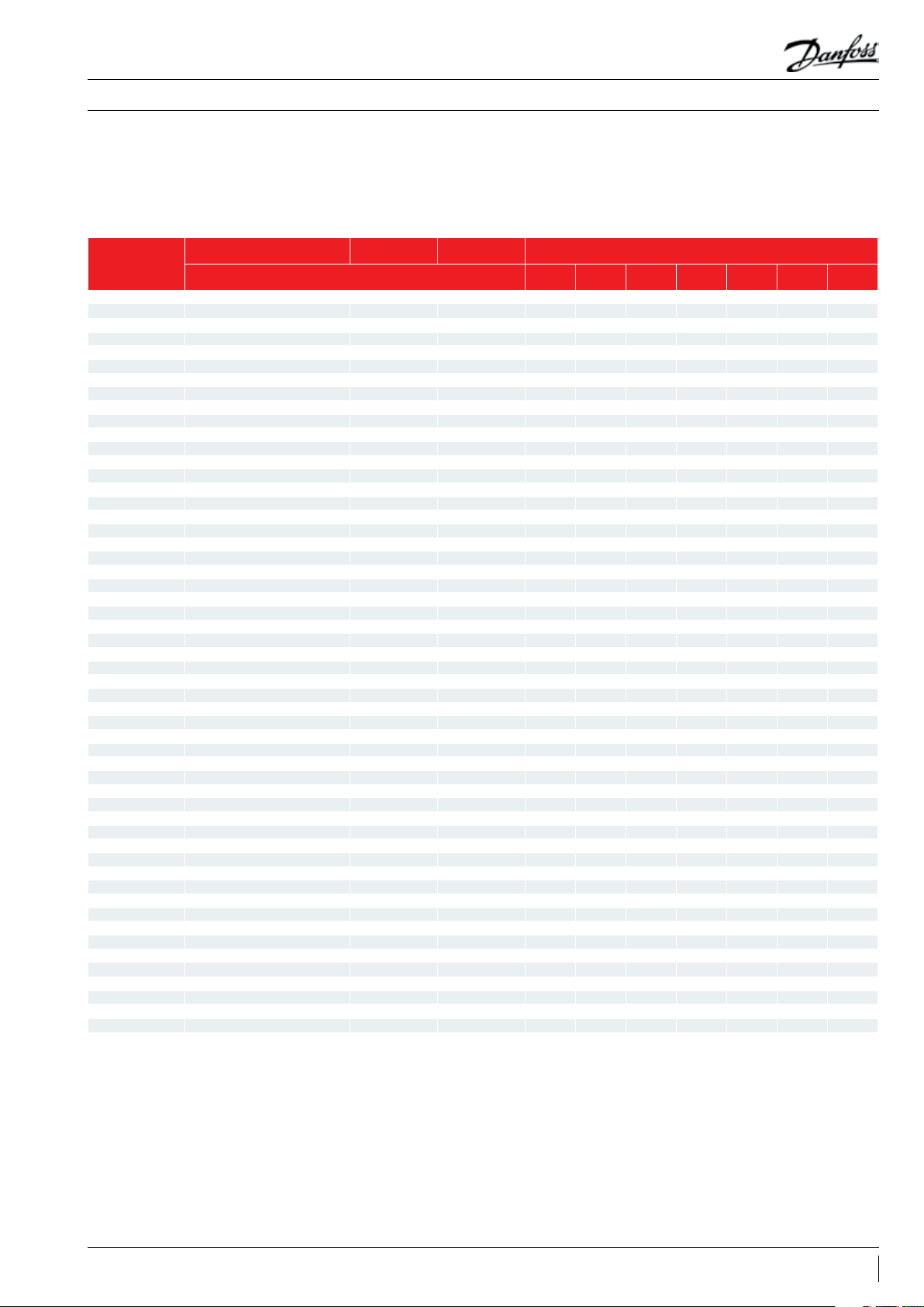
Optyma Plus™ condensing units are pre-parameterized, depending on the model of compressor
mounted and the type of refrigerant. In the case of a “multi-refrigerant” compressor (e.g. MTZ or MLZ),
the controller parameter “o30” for refrigerant is set to R404A and must be changed for other refrigerants
(see chapter Commissioning - Quick start of the unit / Refrigerant change).
TM
Model* Optyma Plus
Code (controller
parameter o61 )*
1 OP-MPHM007NFP00G 114X4101 NF7MLX X x
2 OP-MPHM010SCP00G 114X4102 SC10MLX X x
3 OP-MPHM012SCP00G 114X4104 SC12MLX X x
4 OP-MPHM015SCP00G 114X4105 SC15MLX X x
5 OP-MPHM018SCP00G 114X4109 SC18MLX X x
6 OP-MPGM034GSP00G 114X4210 GS34MFX x
7 OP-MPHM026GSP00G 114X4214 GS26MLX X x
8 OP-MPHM034GSP00G 114X4229 GS34MLX X x
9 OP-MPZM030MTP00E - MTZ22-4VM X x x x x x
10 OP-MPZM048MTP00G - MTZ28-5VM X x x x x x
11 OP-MPZM048MTP00E - MTZ28-4VM X x x x x x
12 OP-MPZM060MTP00G - MTZ36-5VM X x x x x x
13 OP-MPZM060MTP00E - MTZ36-4VM X x x x x x
14 OP-MPZM086MTP00E - MTZ51-4VM X x x x x x
15 OP-MPZM086MTP00H - MTZ50-6VM X x x x x x
16 OP-MPZM108MTP00E - MTZ65-4VM X x x x x x
17 OP-MPZM108MTP00H - MTZ64-6VM X x x x x x
18 OP-MPZM136MTP00E - MTZ81-4VM X x x x x x
19 OP-MPZM136MTP00H - MTZ80-6VM X x x x x x
20 OP-LPHM018SCP00G 114X3109 SC18CLX.2 X x
21 OP-LPHM026GSP00G 114X3217 GS26CLX X x
22 OP-LPHM048NTP00G 114X3225 NTZ48-5VM X x
23 OP-LPHM048NTP00E 114X3233 NTZ48-4VM X x
24 OP-LPHM068NTP00G 114X3241 NTZ68-5VM X x
25 OP-LPHM068NTP00E 114X3249 NTZ68-4VM X x
26 OP-LPHM096NTP00E 114X3357 NTZ96-4VM X x
27 OP-LPHM136NTP00E 114X3365 NTZ136-4VM X x
28 OP-MPUM034MLP00G 114X4261 MLZ015T5LP9 X x x x x x
29 OP-MPUM034MLP00E 114X4264 MLZ015T4LP9 X x x x x x
30 OP-MPUM046MLP00G 114X4281 MLZ021T5LP9 X x x x x x
31 OP-MPUM046MLP00E 114X4284 MLZ021T4LP9 X x x x x x
32 OP-MPUM068MLP00G 114X4308 MLZ030T5LC9 X x x x x x
33 OP-MPUM068MLP00E 114X4311 MLZ030T4LC9 X x x x x x
34 OP-MPUM080MLP00G 114X4321 MLZ038T5LC9 X x x x x x
35 OP-MPUM080MLP00E 114X4324 MLZ038T4LC9 X x x x x x
36 OP-MPUM108MLP00E 114X4344 MLZ048T4LC9 X x x x x x
37 OP-MPUM125MLP00E 114X4414 MLZ058T4LC9 X x x x x x
38 OP-MPUM162MLP00E 114X4434 MLZ076T4LC9 X x x x x x
39 OP-LPHM215LLP00E 114X3476 LLZ024T4LC9 X x
40 OP-LPHM271LLP00E 114X3482 LLZ033T4LC9 X x
41 OP-MPUM057MTP00G 114X4290 MLZ026T5LP9 X x x x x x
42 OP-MPUM057MTP00E 114X4293 MLZ026T4LP9 X x x x x x
43 OP-LPHM067LLP00E - LLZ013T4LC9 X x
44 OP-LPHM084LLP00E - LLZ015T4LC9 X x
45 OP-LPHM098LLP00E - LLZ018T4LC9 X x
46 OP-MPHM024AJP00G 114X4200 CAJ9513Z X
47 OP-MPHM026AJP00G 114X4212 CAJ4517Z X
48
49 OP-MPHM034AJP00G 114X4226 CAJ4519Z X
50 OP-MPHM034AJP00E 114X4227 TAJ4519Z X
51 OP-LPHM026AJP00G 114X3216 CAJ2446Z X
52 OP-MPGM033AJP00G 114X4220 CAJ4511Y x
53 OP-LPHM074FHP00G 114X3252 FH2511Z X
54 OP-LPHM074FHP00E 114X3253 TFH2511Z X
Generation
OP-MPHM026AJP00E 114X4213 TAJ4517Z X
Code (controller parameter o61 ): Code (contrôleur paramètre o61 / Code (Reglerparameter o61) /
Model
: Modèle /
Modell / Model
New
settings are adjustable*
Code-no. Compressor* Refrigerant (controller parameter o30)*
R404A
(19)
R507
(17)
R134a
(3)
R407C
(20)
R22
(2)
Kode (regulatorparameter
R407A**
(21)
o61)
Code-no. : Code n° / Art-Nr. / Bestillingsnr.
Compressor
: Compresseur / Verdichter /
Kompressor
Refrigerant : Réfrigérant (contrôleur paramètre o30) / Kältemittel (Reglerparameter o30) / Kølemiddel (regulatorparameter o30)
*Settings are adjustable : parameters sont réglables / Werte einstellbar / indstillinger er justerbare
**Ongoing qualications for condensing units
R407F**
(37)
3FRCC.ES.010.A4.ML
Page 4
Manual Controller Installation
Annexe
Anhang
Supplement
Les groupes de condensation Optyma Plus™ sont pré-paramétrés, en fonction du modèle de compresseur
et du type de réfrigérant. Dans le cas d’un compresseur «multi-réfrigérants» (p. ex. les modèles MTZ ou
MLZ),
le paramètre du contrôleur «o30» pour le réfrigérant est déni sur R404A et doit être modié en
cas d’utilisation d’un réfrigérant diérent (voir le chapitre Mise en service - Démarrage rapide de l’unité
/ Changement de réfrigérant).
Optyma Plus™ Verüssigungssätze sind vorparametriert für das installierte Verdichtermodell und verwendete
Kältemittel. Im Fall eines Verdichters für mehrere Kältemittel (z.B. MTZ oder MLZ) ist der Reglerparameter
o30 für das Kältemittel auf „R404A“ eingestellt. Der Parameter muss für andere Kältemittel geändert
werden (siehe Kapitel zu Inbetriebnahme – Schnellstart der Einheit/Kältemittelwechsel).
Optyma Plus™-kondenseringsaggregater er parameterafstemt på forhånd afhængigt af den monterede
kompressormodel og kølemiddeltypen. I tilfælde af en kompressor til ere kølemidler (f.eks. MTZ eller
MLZ) er regulatorparameteren ”o30” indstillet til f.eks. R404A og skal ændres ved anvendelse af andre
kølemidler (se kapitlet Idriftsættelse – hurtig start af enheden/kølemiddelskift).
room thermostat
Raumthermostat
thermostat d'ambiance
-B1
-R1 -R2
T>
P
1 2 3
U
-R3 -R4
-B2
P
1 2 3
U
-F1
3,15A
BN
BU
BU
333443
PE
-Q1
1 3 5
I > I > I >
2 4 6
-X1
L N PE
power supply
Zuleitung
alimentation
220-240V1N~/50Hz
BKBKBK
BK
BK
GY
12345
BKBKRD
BK
24
25
BRBRGY
WH
-K2
6
BN
-M1
compresseur
BU
10
11
14
12
13
13
M
1~
compressor
Verdichter
-C1
-C2
-X1 N1
-B5
*Option
123
.
2
5
6
.
6
-X1 14
BK
M
-M2
1~
BL
BR
-C3
.
PE
fan motor
Lüftermotor
ventilateur
1
P>
10111213141516
A1
-K2
A2
crankcase heater
Kurbelwannenheizung
résistance de carter
-K2
.
-R5
21
22
22
23
.
22
-X1
P>
-B3
.
20
-X1
P<
-B4
.
15
-X1
.
.
N2
PE
-K1
44
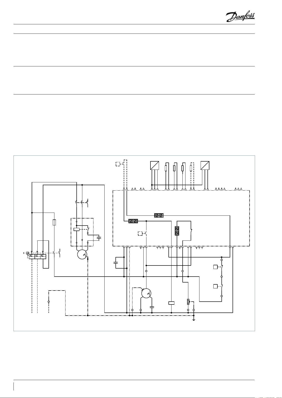
*Option: A fan pressure switch or fan speed controller can be connected in series to wire n°6
Il est possible de raccorder en série un pressostat ou un contrôleur de vitesse pour le ventilateur au l 6.
An die Ader n°6 kann ein Lüfterdruckschalter oder ein Lüfterdrehzahlregler in Reihe geschaltet werden.
* Valgfrit: En ventilatortrykkontakt eller ventilatorhastighedsregulator kan serieforbindes til ledning nr. 6
4 FRCC.ES.010.A4.ML
Page 5
Manual Controller Installation
4 8213 7
65
BK
BK
BK
BK
BK
BK
GY
GY
BK
BK
BN
BN
T>
thermostat d'ambiance
Raumthermostat
n-min
set
n-max
E1
ON
OFF
S1
PKE-6
régulation de vitesse 0-10V
Drehzahlsteller 0-10V
speed controller 0-10V
PEPEPE
L1NU1
U1
U2
U2D1GDA1GD
GD
E1
+
GD
-A1
-R1 -R3 -R4-R2
P
U
123
-B1
Option: Room thermostat
limit switch
Endschalter
interrupteur
13
14
-S1
2
.
-X1
1
.
-X1
N1
.
-C1
BU
BU
BN
N2
.
-C2
PE
.
BN
N3
.
PE
.
-X1
BK
BK
3
.
-X1
BNBN
BN
P
U
123
-B2
22
.
-X1
15
.
-X1
20
.
-X1
P<
-B4
14
.
P>
-B3
P>
1
*Option
-B5
2
BNBKGY
I > I > I >
135
246
-Q1
333443
44
3A
-F1
BNBKGY
T1 T2 T3
BU
25
24
123
5
6
10111213141516
22
23
12345
6
-K2
21
22
-K2
A1
A2
-K2
A1
A2
-K3
12(1) 1 4(5)
11(9)
-K3
12(1)
14(5)
11(9)
-K4
A1
A2
-K4
12(4) 14(8)
11(12)
-K3
12(4) 14(8)
11(12)
-K4
M
3~
compressor
Verdichter
compresseur
-M1
BKBUBN
WH
WH
1~
M
GNYE
fan motor 1
Lüftermotor 1
ventilateur 1
-M2
BKBUBN
WH
WH
1~
M
GNYE
fan motor 2
Lüftermotor 2
ventilateur 2
-M3
PE
.
N4
.
crankcase heater
Kurbelwannenheizung
résistance de carter
-R5
power supply
Zuleitung
compresseur
380-400V3N~/50Hz
L1 L2 PEL3 N
PE
N
.
-X1
5FRCC.ES.010.A4.ML
Page 6

Manual Controller Installation
Contents
Commissioning ................................................................................................................. 7
Electrical installations ................................................................................................................................................... 7
Main display (after controller start-up) ...................................................................................................................7
Parameter Menu ............................................................................................................................................................. 7
Quick start of the unit / Refrigerant change.........................................................................................................7
Pump Down - Function ................................................................................................................................................ 8
Day/Night - Function .....................................................................................................................................................8
Service and Maintenance ................................................................................................ 8
Main Display .................................................................................................................................................................... 8
Operating Parameters .................................................................................................................................................. 8
Alarm and Error Messages...........................................................................................................................................9
Repair ................................................................................................................................ 9
Controller failure ............................................................................................................................................................. 9
Factory reset ..................................................................................................................................................................... 9
Controller Replacement of a unit on site .............................................................................................................. 10
Control.............................................................................................................................. 10
Control of condensing pressure...............................................................................................................................10
Control of crankcase heater .......................................................................................................................................10
Control of Fan Speed ....................................................................................................................................................10
Safety Parameter “Low Pressure” for R404A ....................................................................................................... 11
Safety Parameter “High Pressure” for R404A ...................................................................................................... 11
6 FRCC.ES.010.A4.02
Page 7
Manual Controller Installation
Commissioning
Electrical installations
Main display (after controller
start-up)
Parameter Menu
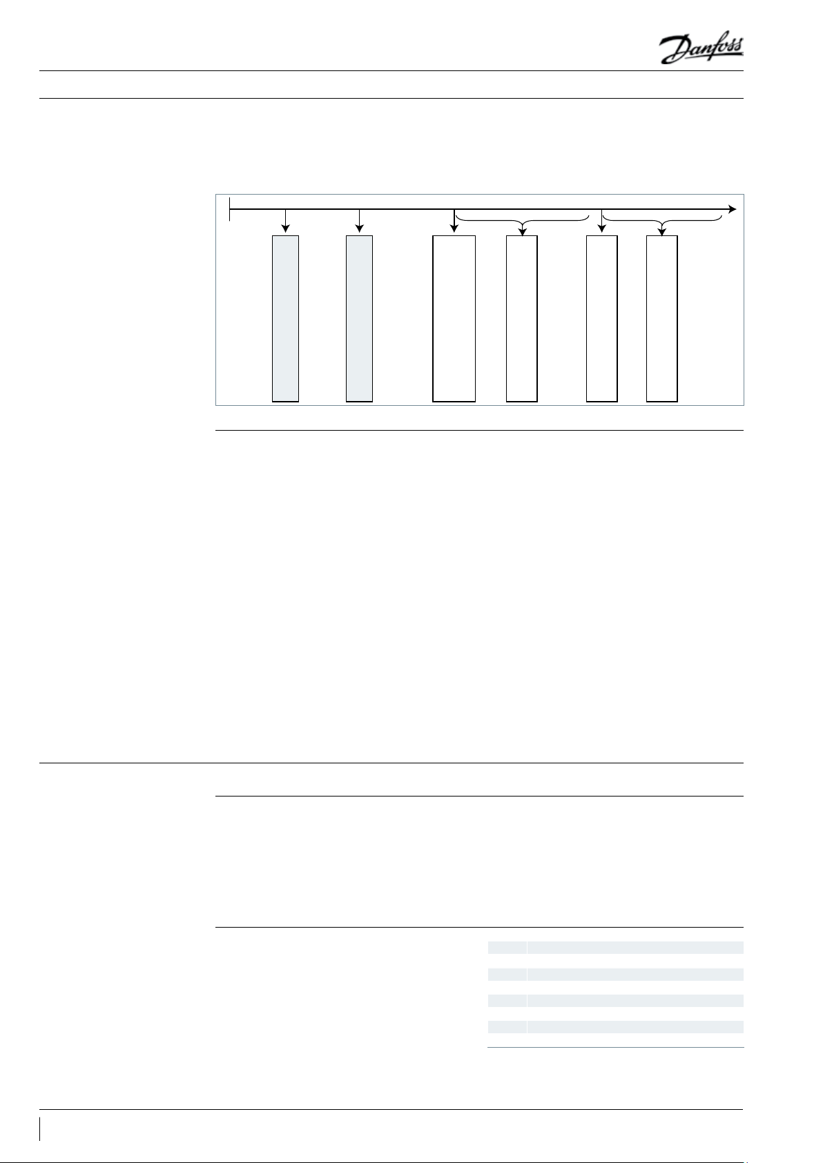
• Arrange electrical connections as mentioned in the table below
• Remove temporarily bridge DI1 (terminals 24 - 25 of the controller) to get access to parameters and
values of the controller without starting the condensing unit
Room Thermostat control without Pump Down
R404A *
function
- Connect Room Thermostat to these terminals
with factory delivered low pressure transmitter
- Connect power supply to main switch acc. wiring diagram, located in front door inner side
R404A *
Pump Down control
- Connect power supply to main switch acc. wiring diagram, located in front door inner side
- Increase the Setting of controller Par. c33 (Pump
Down CUT-OUT value):
e.g. Piston : 0,7bar
e.g. Scroll : 1,7bar
Note: To avoid low pressure alarm, the Setting of
c33 should be higher than c75
*: change for other refrigerants following chapters.
• The controller’s screen displays the Evaporation Temperature in °C
• Press short the lower button of the controller to show the Condensing Temperature in °C
• After a few seconds the display returns to the Evaporation Temperature in °C
• To get access to parameter menu press 5 seconds the upper button of the controller
• The rst Parameter “r05” of the Parameter menu will be shown on the display
• Press short the upper (or lower) button to go to the next Parameter of the Parameter menu. Scroll fast
through the Parameters with a long press on these buttons
• Press short the middle button to show the value of the selected Parameter
• Press afterwards the upper (or lower) button to change the value of the selected parameter. A long
press on these buttons will change the value fast
• The value will be stored after 20 seconds without any action or with a short press on the middle button
• After 20 seconds without pressing any button, the display returns to the main screen, the evaporation
temperature in °C. The parameter menu is closed now, to go back to the parameter menu press again
upper button 5 seconds …
Quick start of the unit /
Refrigerant change
• Optyma Plus™ new generation is preset, depending on the compressor model and refrigerant type.
In the case of a “multi-refrigerant” compressor, the controller of the condensing unit is set for R404A
(see table on page3). If this factory setting ts for the requirement of your application, no controller
parameter must be changed.
• For a refrigerant change go into the parameter menu (press upper button 5 seconds)
• Select parameter “r12” (software main switch) with a short press on lower button
• Activate parameter “r12” with middle button and change the value to 0 (zero)
• Conrm the value with a short press on the middle button (the 3 LED’s start ashing)
• Go to the parameter “o30” (Refrigerant)
• Change the value to 3 (stands for R134a), or 17 (R507), or 20 (R407C), or 19 (R404A)
• Conrm the value with a short press on the middle button
• Select parameter “r12” again
• Change the value to 1 (one)
• Conrm the value with a short press on the middle button (the 3 LED-signs stop ashing and the condensing unit will start if required)
• After 20 seconds the display returns to the evaporation temperature in °C, the new refrigerant and all
relevant parameters are changed
7FRCC.ES.010.A4.02
Page 8
Manual Controller Installation
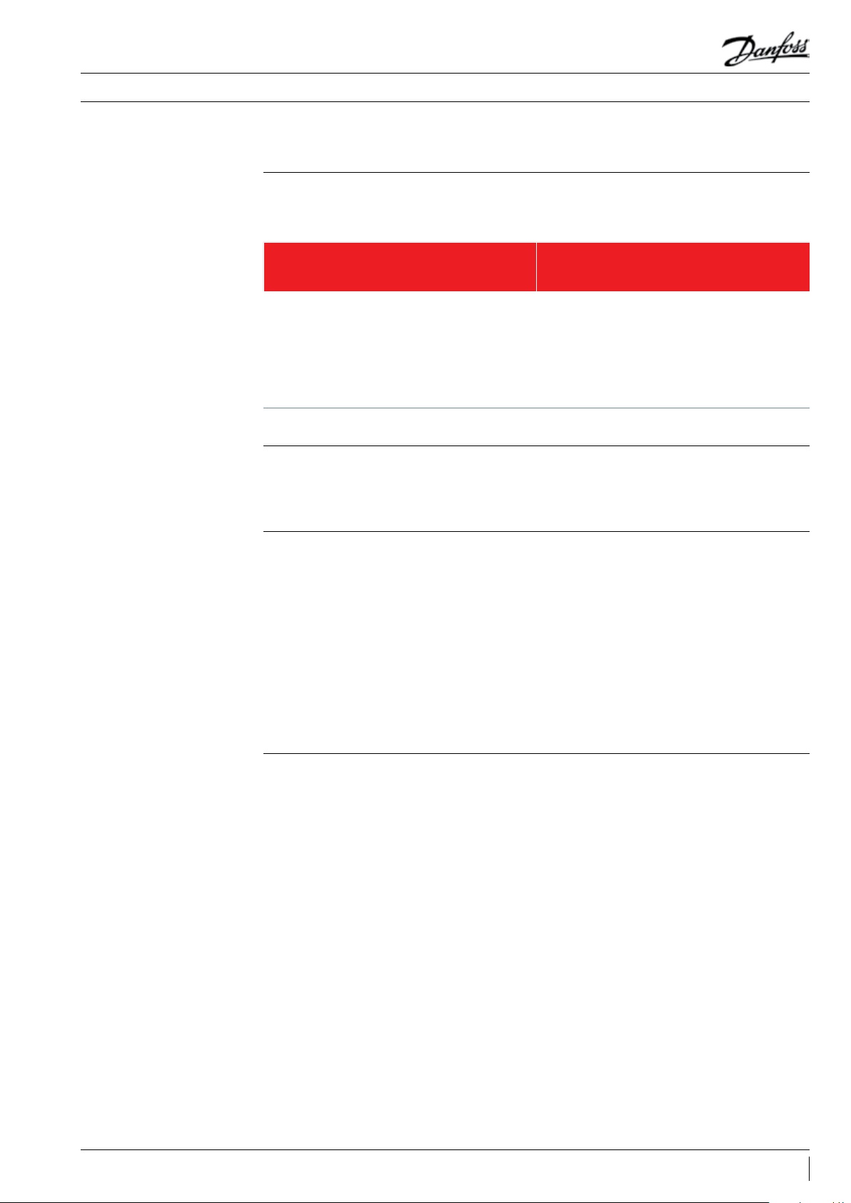
Pump Down - Function • A “pump-down” limit can be activated with the setting of parameter c33
• To avoid unwanted low pressure alarms, the setting ot this parameter should be higher than the low
pressure cut-out limit parameter c75, … e.g. below
0
meter c75
Day/Night - Function
Scroll: 0,5bar Recip: -0,3bar
Low pressure switch: Cut-Out
Scroll: 1,5bar Recip: 0,5bar
Low pressure switch: Cut-In
Low pressure cut-out limit: Para-
Scroll: 1,4bar Recip: 0,4bar
Scroll and Recip: 0,7bar
Dierential: Parameter c76
Scroll: 1,7bar Recip: 0,7bar
Pump down function: Param. c33
Scroll and Recip: 0,7bar
Dierential: Parameter c76
In some areas it may be necessary to reduce noise level during night time. This is possible with the “Day
/ Night” function of the Optyma Plus™ controller which limits the fan speed. For activation follow the
next steps …
• Activate the parameter menu (press upper button min. 5 sec.)
• Select parameter “r13” Night Oset (temperature oset related to condensing temperature setpoint
for daytime which is parameter “r29”)
• Push middle button and set the desired value, e.g. 005 for 5 Kelvin
• Conrm the value with a short press on the middle button. Do the same with the next parameters
which are required for the “Day / Night” - function …
• Select and set parameter “t17” Day start (hours), e.g. 006 for 06:00 a.m.
• Select and set parameter “t18” Night start (hours), e.g. 022 for 22:00 p.m.
• Select and set parameter “t07” Clock setting (hours), e.g. 011 for 11:xx a.m.
• Select and set parameter “t08” Clock setting (minutes), e.g. 035 for 11:35 a.m.
• Select and set parameter “t45” Clock setting (date), e.g. 010 for 10.xx.xx
• Select and set parameter “t46” Clock setting (month), e.g. 004 for 10.04.xx
• Select and set parameter “t47” Clock setting (year), e.g. 012 for 10.04.12
• All values will be stored with the middle button or after 20s without pressing any button
Service and Maintenance
Main Display
(Evaporating and Condensing
Temperature, Setpoint Temperature Dierence)
Operating Parameters
8 FRCC.ES.010.A4.02
• The controller displays the evaporation temperature in °C (main screen)
• It will show the readout of the condensing temperature in °C after pressing short the lower button
• Pressing short the middle button, the setpoint of the temperature dierence between condensing
and ambient temperature appears which can be directly modied here by pressing the upper or lower
button.
• The display returns to main screen after a few seconds without any action on the buttons
• Operation conditions of the condensing unit can
be displayed in the parameter menu by selecting parameters “U” … below some examples
u01 Condensing Pressure
u10 Status of DI1 (room thermostat)
u21 Superheat
U22 Condensing Temperature
U23 Evaporation Pressure
U24 Evaporation Temperature
U25 Ambient Temperature
U26 Discharge Temperature
U27 Suction Temperature
Page 9

Manual Controller Installation
Alarm and Error Messages
Repair
Controller failure
(if the controller fails, there is a
possibility to run the condensing
unit in “manual” mode. Proceed as
follows)
• In case of “malfunctions” 3 small LED symbols
will ash on the controller’s screen. Acknowledge with a short press on upper button. Here
some examples below …
A2 Low Suction Pressure Alarm
Safety Input Alarm (DI3: High condensing
A17
/ low suction pressure)
A96 Discharge Gas Temperature High
E20 Condensing Pressure Transmitter Error
E31 Ambient Temperature Sensor Error
E32 Discharge Temperature Sensor Error
E33 Suction Gas Temperature Sensor Error
E39 Evaporating Pressure Transmitter Error
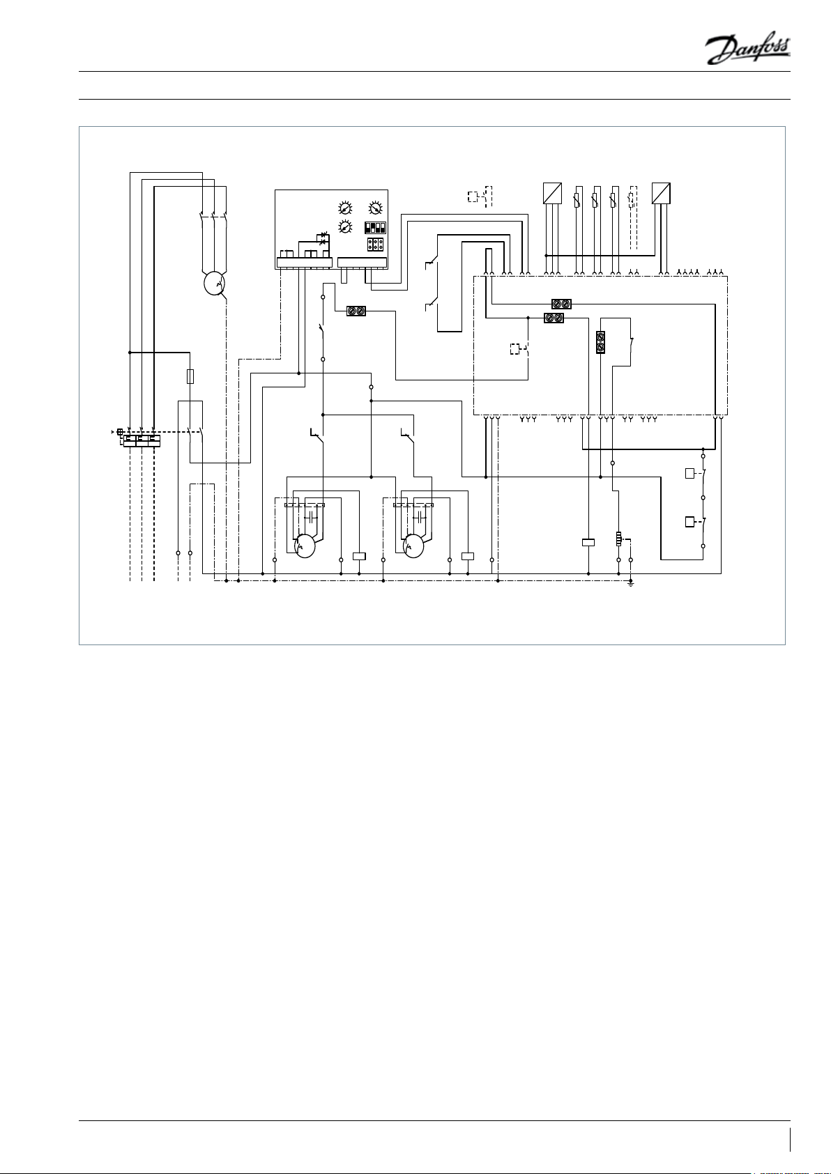
• See wiring diagrams on p. 4-5.
• Disconnect the condensing unit from power supply (turn hardware main switch o)
• Remove wire from controller terminal 22 (safety input DI3) and terminal 25 (room thermostat DI1) and
put them together
• Remove wire from controller terminal 24 (room thermostat DI1) and terminal 11 (compressor supply)
and put them together
• H1, H2, H3 : Remove wire 6* and connect it with terminal bridge for wire 11 and 24.
• H4 : Remove wire U2* from fan speed controller and connect it with wire 11 and 24.
• Remove wire from controller terminal 14 (crankcase heater) and connect it to compressor contactor K2
terminal 22
• Remove wire from controller terminal 12 (supply crankcase heater), extend this wire approximately
40cm and connect it to compressor contactor K2 terminal 21
• Pay attention: Remove the big terminal block from the controller or remove the complete controller
• Connect the condensing unit back to power supply (turn hardware main switch on)
Factory reset
(all factory parameters can be
restored by the following
procedure)
• Turn OFF the main power switch
• While holding simultaneously the up and down button, turn ON the main switch
• Message FAC is displayed, means “FACTORY RESET” restores factory settings
• After a short time message “typ” appears on the screen
• Activate parameter menu and go to parameter o61 (unit type)
• Enter the value 1 to 42 depending on the type of condensing unit (see table 1 on page 3)
• Store the entered value by pressing the middle button of the controller
• After 15 seconds without action the message “ref” appears on the screen
• Activate parameter menu and go to parameter o30 (refrigerant)
• Change the value to 3 (stands for refrigerant R134a), or 17 (R507), or 20 (R407C), or 19 (R404A)
• Store the entered value by pressing the middle button of the controller
• Go to parameter o67 (store values as factory setting)
• Change the value to “on”
• Validate the parameter entered by pressing the middle button of the controller
• After 15 seconds without action the message “OFF” appears on the screen
• Activate parameter menu and go to parameter r12 (main switch)
• Change the value to 1 (condensing unit will start if cooling demand from cold room controller)
• The “Day / Night” function must be reprogrammed too (see chapter Commissioning - Day/Night
- Function)
9FRCC.ES.010.A4.02
Page 10

Manual Controller Installation
Controller Replacement of a
unit on site
Control
Control of condensing pressure
Control of crankcase heater
• Turn OFF the main power switch
• Remove the new controller (remove all plugs, 2 x I-type screws and controller)
• Install the new controller
• Turn ON main power switch again, no factory reset needed
• After a short time message “typ” appears on the screen
• Follow same steps as shown in preceding chapter fth row and following
spare part code controller SINGLE pack: 118U3465
spare part code controller MULTI pack (12pcs.) : 084B8135
• The setpoint of the condensing temperature is calculated from the measured ambient temperature
plus an adjustable Temperature Oset (called Reference) and controlled by the fan speed
• Factory setting of Reference = 8.0K
• The Reference is accessible by pressing short the middle button of the controller
• When Reference is shown, it can be modied with the upper or lower button
• Additionally to this the control of the condensing temperature can be limited by following parameters:
“r82” = minimal condensing temperature (factory set: 10.0°C)
“r83” = maximal condensing temperature (factory set: 40.0°C)
• The controller optimizes the regulation of the crankcase heater itself. The heating power depends on
the ambient temperature and suction pressure and is controlled by Pulse Width modulation
• There is no change of parameters “P45”, “P46” and “P47” necessary on site
Control of Fan Speed
• The fan speed is controlled by PI-control, depends on the actual value and the setpoint of the condensing temperature
• There is no change of parameters “F14” and “F21” to be provided on site
10 FRCC.ES.010.A4.02
Page 11

Manual Controller Installation
Safety Parameter “Low
Pressure” for R404A
0
Suction Pressure
Safety Parameter “High
Pressure” for R404A
Scroll: 0,5bar Recip: -0,3bar
Low pressure switch: Cut-Out
Min. suction pres.: Param. c75
“Mechanical“ Safety - LP
Scroll: 1,4bar Recip: 0,4bar
“Electronic“ Safety - LP
Scroll: 1,5bar Recip: 0,5bar
Low pressure switch: Cut-In
0
Scroll and Recip: 24bar
High pressure switch: Cut-In
Scroll and Recip: 3,0bar
Dierential: Parameter c74
Scroll + "blue" Recip.: 28bar
Max. Pressure: Parameter c73
"black" Recip.: 23bar
Scroll and Recip: 0,7bar
Dierential: Parameter c76
Discharge Pressure
Scroll and Recip: 31bar
High pressure switch: Cut-Out
“Mechanical“ Safety - HP
“Electronic“ Safety - LP
11FRCC.ES.010.A4.02
Page 12

Manuel Mise en service du contrôleur
Sommaire
Mise en service ................................................................................................................ 13
Installations électriques .............................................................................................................................................. 13
Écran principal (après le démarrage du contrôleur) .........................................................................................13
Menu des paramètres .................................................................................................................................................. 13
Démarrage rapide de l’unité/Changement de réfrigérant ............................................................................ 13
Fonction «pump-down» ............................................................................................................................................. 14
Fonction Jour/Nuit .......................................................................................................................................................14
Service et maintenance .................................................................................................. 14
Écran du contrôleur - Achage «permanent» .........................................................................................................14
Visualisation des paramètres de fonctionnement ............................................................................................14
Alarmes et messages d’erreur ...................................................................................................................................15
Dépannage ...................................................................................................................... 15
Défaillance du contrôleur ........................................................................................................................................... 15
Réinitialisation du paramétrage usine...................................................................................................................15
Remplacement du contrôleur d’une unité sur site ........................................................................................... 16
Régulation ....................................................................................................................... 16
Régulation de la condensation ................................................................................................................................ 16
Régulation de la résistance de carter ..................................................................................................................... 16
Régulation de la vitesse de rotation du ventilateur ......................................................................................... 16
Paramétrage de sécurité côté «basse pression» pour le R404A.................................................................17
Paramétrage de sécurité côté «haute pression» pour le R404A ................................................................ 17
12 FRCC.ES.010.A4.04
Page 13

Manuel Mise en service du contrôleur
Mise en service
Installations électriques
Écran principal (après le
démarrage du contrôleur)
Menu des paramètres
• Eectuez les raccordements électriques comme indiqué dans le tableau ci-dessous.
• Retirez temporairement le raccord DI1 (bornes 24 et 25 du contrôleur), an d'accéder aux paramètres
et aux valeurs du contrôleur sans avoir à démarrer le groupe de condensation.
Régulation par thermostat d'ambiance sans
R404A *
fonction
pump down
- Connectez le thermostat d'ambiance à ces
bornes
- Connectez l'alimentation électrique au
sectionneur
principal conformément au schéma
électrique, situé sur la face interne de la porte
avant
avec transmetteur de basse pression livré d'usine
- Connectez l'alimentation électrique au
sectionneur
principal conformément au schéma
électrique, situé sur la face interne de la porte
avant
- Augmentez la valeur du paramètre c33 du
contrôleur
(valeur de COUPURE pump down):
R404A *
Régulation pump down
Exemple piston: 0,7bar
Exemple Scroll: 1,7bar
Remarque: An d'éviter les alarmes de basse
pression, la valeur du paramètre c33 doit être
supérieure à celle du paramètre c75.
*: la procédure à eectuer pour les autres réfrigérants est décrite dans les chapitres qui suivent.
• L'écran du contrôleur ache la température d'évaporation en °C.
• Appuyez brièvement sur le bouton inférieur du contrôleur pour acher la température de
condensation en °C.
• Après quelques secondes, l'écran ache à nouveau la température d'évaporation en °C.
• Pour accéder au menu des paramètres, appuyez 5 secondes sur le bouton supérieur du contrôleur.
• Le premier paramètre du menu, le paramètre «r05» s'ache alors sur l'écran.
• Appuyez brièvement sur le bouton supérieur (ou inférieur) pour accéder au paramètre du menu
suivant. Pour faire déler rapidement les paramètres, appuyez longuement sur ces boutons.
• Appuyez brièvement sur le bouton du milieu pour acher la valeur du paramètre sélectionné.
• Appuyez ensuite sur le bouton supérieur (ou inférieur) pour modier la valeur du paramètre
sélectionné. Appuyez longuement sur l’un de ces boutons pour modier rapidement la valeur.
• La valeur est enregistrée après 20 secondes sans aucune action ou si vous appuyez brièvement sur le
bouton du milieu.
• Si aucun bouton n'est actionné pendant 20 secondes, l'écran principal s'ache à nouveau et indique
la température d'évaporation en °C. Le menu des paramètres est à présent fermé, pour y revenir,
appuyez à nouveau 5 secondes sur le bouton supérieur.
Démarrage rapide de l'unité/
Changement de réfrigérant
• L'Optyma Plus™ nouvelle génération est préparamétré, en fonction du modèle de compresseur et du
type de réfrigérant. Dans le cas d'un compresseur «multiréfrigérant», le contrôleur du groupe de
condensation est conguré pour utiliser du R404A (voir le tableau à la page 3). Si ce réglage d'usine
répond aux besoins de votre application, les paramètres du contrôleur n'ont pas à être modiés.
• Pour changer de réfrigérant, accédez au menu des paramètres (appuyez sur le bouton supérieur
pendant 5 secondes).
• Sélectionnez le paramètre « r12 » (sectionneur principal) en appuyant brièvement sur le bouton
inférieur.
• Activez le paramètre «r12» à l'aide du bouton du milieu et sélectionnez sa valeur sur 0 (zéro).
• Conrmez cette valeur en appuyant brièvement sur le bouton du milieu (les 3 LED se mettent alors à
clignoter).
• Accédez au paramètre «o30» (Réfrigérant).
• Sélectionnez sa valeur sur 3 (pour le R134a), 17 (R507), 20 (R407C) ou 19 (R404A).
• Conrmez cette valeur en appuyant brièvement sur le bouton du milieu.
• Sélectionnez à nouveau le paramètre «r12».
• Sélectionnez sa valeur sur 1 (un).
• Conrmez cette valeur en appuyant brièvement sur le bouton du milieu (les 3 LED s'arrêtent alors de
clignoter et le groupe de condensation démarre si nécessaire).
• Après 20 secondes, l'écran ache à nouveau la température d'évaporation en °C, le réfrigérant et tous
les paramètres liés à ce refrigérant sont modiés.
13FRCC.ES.010.A4.04
Page 14

Manuel Mise en service du contrôleur
Fonction «pump-down»
• Une valeur limite du «pump-down» peut être activée à l’aide du paramètre c33.
• La valeur de ce paramètre devra être supérieure à celle du paramètre c75 (valeur limite de la coupure
sécurité BP), pour éviter une alarme basse pression indésirable.
Pression basse transducteur: Cut-Out
paramètre c75
Scroll: 1,4bar Piston: 0,4bar
c76
Scroll ou Piston: 0,7bar
0
Scroll: 0,5bar Piston: -0,3bar
Pression basse pressostat: Cut-Out
Fonction Jour/Nuit Dans certains endroits, il peut être nécessaire de réduire le niveau sonore durant la nuit. Pour ce faire,
Scroll: 1,5bar Piston: 0,5bar
Pression basse pressostat: Cut-In
Scroll: 1,7bar Piston: 0,7bar
Pump-Down paramètre c33
c76
Scroll ou Piston: 0,7bar
vous pouvez utiliser la fonction « Jour/Nuit » du contrôleur Optyma Plus™, qui limite la vitesse du
ventilateur. Pour activer cette fonction, eectuez les étapes suivantes…
• Activez le menu des paramètres (appuyez sur le bouton supérieur pendant au moins 5 secondes).
• Sélectionnez le paramètre «r13», décalage nocturne (le décalage de température est lié au point de
consigne de la température de condensation en journée, qui est déni par le paramètre «r29»).
• Appuyez sur le bouton du milieu et dénissez la valeur de votre choix, p. ex. 005 pour 5K.
• Conrmez cette valeur en appuyant brièvement sur le bouton du milieu. Répétez cette procédure
pour les autres paramètres à dénir pour la fonction «Jour/Nuit»…
• Sélectionnez et réglez le paramètre «t17» Démarrage jour (heure), p. ex. 006 pour 06h00
• Sélectionnez et réglez le paramètre «t18» Démarrage nuit (heure), p. ex. 022 pour 22h00
• Sélectionnez et réglez le paramètre «t07» Réglage de l'horloge (heure), p. ex. 011 pour 11hxx
• Sélectionnez et réglez le paramètre «t08» Réglage de l'horloge (minutes), p ex. 035 pour 11h35
• Sélectionnez et réglez le paramètre «t45» Réglage de l'horloge (jour), p. ex. 010 pour le 10/xx/xx
• Sélectionnez et réglez le paramètre «t46» Réglage de l'horloge (mois), p. ex. 004 pour le 10/04/xx
• Sélectionnez et réglez le paramètre «t47» Réglage de l'horloge (année), p. ex. 012 pour le 10/04/12
• Pour enregistrer ces valeurs, appuyez sur le bouton du milieu ou n'appuyez sur aucun bouton pendant
20 secondes
Service et maintenance
Écran du contrôleur - Achage
«permanent»
(Températures d'évaporation et
de condensation, diérence de
température de point de consigne)
Visualisation des paramètres de
fonctionnement
14 FRCC.ES.010.A4.04
• Le contrôleur ache la température d’évaporation en °C (écran principal).
• Il indique la température de condensation mesurée en °C lorsque vous appuyez brièvement sur le
bouton inférieur.
• Lorsque vous appuyez brièvement sur le bouton du milieu, le point de consigne de diérence de
température entre les températures de condensation et ambiante s’ache et peut être directement
modié en appuyant sur le bouton supérieur ou inférieur.
• Au bout de quelques secondes, l’acheur revient sur la température d’évaporation en °C.
• Les conditions de fonctionnement du groupe de
condensation peuvent être achées dans le menu
des paramètres en sélectionnant les paramètres
«U»…voir les exemples ci-dessous.
U01 Pression de condensation
U10 État de DI1 (thermostat d'ambiance)
U21 Surchaue
U22 Température de condensation
U23 Pression d'évaporation
U24 Température d'évaporation
U25 Température ambiante
U26 Température de refoulement
U27 Température d'aspiration
Page 15

Manuel Mise en service du contrôleur
Alarmes et messages d’erreur
Dépannage
Défaillance du contrôleur
(En cas de défaillance du contrôleur,
il est possible de faire fonctionner
le groupe de condensation en
mode «manuel», moyennant
quelques adaptations mineures.
Pour ce faire, eectuez la
procédure suivante.)
• En cas de «dysfonctionnement» de l’installation,
3 petites LED, au niveau de l’écran du contrôleur,
se mettent à clignoter. Pour accéder au code
«Erreur», appuyez sur le bouton supérieur. Voici
quelques exemples:
A2 Alarme BP – Pression d’aspiration trop basse
A17
Alarme BP ou HP (Mécanique)
A96
Alarme température de refoulement trop élevée
E20 Incident sur capteur de pression HP
E31
Incident sur la sonde d’ambiance S2
E32
Incident sur la sonde température de refoulement S3
E33 Incident sur la sonde température d’aspiration S4
E39
Incident sur capteur de pression BP
• Voir les schémas de câblage sur p. 4-5.
• Coupez l’alimentation générale au niveau de l’unité de condensation (sélectionneur principal).
• Retirez le l de la borne 22 (entré de sécurité DI3), ainsi que celui de la borne 25 (thermostat de la
chambre froide DI1) et les raccordez entre eux.
• Retirez le l de la borne 24 (thermostat de la chambre froide DI1), ainsi que celui de la borne 11
(alimentation du compresseur) et les raccordez entre eux.
• H1, H2, H3 : Retirez le l 6* et le raccordez avec un « domino » pour les ls 11 et 24.
• H4 : Retirez le l U2* du régulateur de vitesse du ventilateur et le raccordez avec les ls 11 et 24.
• Retirez le l de la borne 14 (résistance de carter) et le raccordez à la borne 22 du contacteur K2 du
compresseur.
• Retirez le l de la borne 12 (alimentation résistance de carter), rallongez ce l d’environ 40 cm et le
raccordez à la borne 21 du contacteur K2 du compresseur.
• Attention : Retirez, du contrôleur, le large bloc de raccordements, ou l’ensemble du contrôleur.
• Remettez sous tension l’unité de condensation (sélectionneur principal).
Réinitialisation du paramétrage
usine
(vous pouvez restaurer tous les
réglages d'usine en eectuant la
procédure suivante)
• Coupez l’alimentation générale au niveau du sectionneur.
• Appuyez simultanément sur les boutons supérieur et inférieur du contrôleur, et réenclenchez le sectionneur
tout en maintenant la pression sur les boutons supérieur et inférieur.
• Le message «FAC» (pour FACTORY RESET ) s’ache, ce qui signie que la réinitialisation des réglages d’usine
est lancée.
• Après quelques instants, le message «typ» s’ache à l’écran.
• Avec le menu déroulant accédez, au paramètre o61 (type de groupe).
• Saisissez une valeur comprise entre 1 et 42 en fonction du type de groupe de condensation (voir le tableau
1 à la page 3).
• Validez le paramètre saisi en appuyant sur le bouton du milieu du contrôleur.
• Après 15 secondes sans aucune action, le message «ref» s’ache à l’écran.
• Avec le menu déroulant, accédez au paramètre o30 (réfrigérant).
• Sélectionnez sa valeur sur 3 (pour le R134a), 17 (R507), 20 (R407C) ou 19 (R404A).
• Validez le paramètre saisi en appuyant sur le bouton du milieu du contrôleur.
• Avec le menu déroulant, accédez au paramètre o67 (enregistrer les valeurs comme réglages d’usine).
• Sélectionnez sa valeur sur «ON» (activer).
• Validez le paramètre saisi en appuyant sur le bouton du milieu du contrôleur.
• Après 15 secondes sans aucune action, le message «OFF» (désactivé) s’ache à l’écran.
• Avec le menu déroulant, accédez au paramètre r12 (sectionneur principal).
• Sélectionnez sa valeur sur 1 (démarrage du groupe de condensation en cas de demande de la part du
contrôleur de chambre froide).
• La fonction « Jour/Nuit» doit également être reprogrammée (voir le chapitre Mise en service - Jour/Nuit
- Fonction).
15FRCC.ES.010.A4.04
Page 16

Manuel Mise en service du contrôleur
Remplacement du contrôleur
d’une unité sur site
Régulation
Régulation de la condensation
• Coupez l’alimentation générale au niveau du séctionneur.
• Retirez l’ancien contrôleur (retirez toutes les prises, les deux vis type I et le contrôleur).
• Câbler électriquement le nouveau contrôleur sur l’unité de condensation
• Mettez l’interrupteur d’alimentation principale sous tension
• Après quelques instants, le message «typ» s’ache à l’écran.
• Suivez les étapes de la section précédente, à partir de la cinquième ligne.
pièce de rechange, code du contrôleur à l’unité: 118U3465
pièce de rechange, code du contrôleur en multi-pack (12 pcs) : 084B8135
• Le point de consigne de régulation de la température de condensation est égal à:
o Température Ambiante Extérieure + Delta T
o avec Delta T = 8.0K (paramétré en usine)
• Ce Delta T est accessible directement en exerçant une pression sur le bouton du milieu du contrôleur
• A ce stade, en appuyant sur le bouton du haut (ou du bas) la valeur « usine » (8.0K) est augmentée (bouton
du haut) ou diminuée (bouton du bas) à chacune des impulsions exercées
• De plus, la possibilité est oerte de limiter cette variation du point de consigne en agissant sur les paramètres
« r82 » et « r83 » du menu déroulant
«r82»=température de condensation minimale (réglage d'usine: 10,0°C)
«r83»=température de condensation maximale (réglage d'usine: 40,0°C)
Régulation de la résistance
de carter
Régulation de la vitesse
de rotation du ventilateur
• Le contrôleur, de par les paramètres rentrés en usine, assure une optimisation de la régulation de la
résistance de carter (temps de fonctionnement et puissance de chaue)
• Aucune modication des paramètres «P45», «P46» et «P47» n’est à prévoir sur site.
• Le contrôleur, de par les paramètres rentrés en usine, assure une optimisation de la régulation de la
vitesse de rotation du ventilateur.
• Aucune modication des paramètres «F14» et «F21» n’est à prévoir sur site.
16 FRCC.ES.010.A4.04
Page 17

Manuel Mise en service du contrôleur
Paramétrage de sécurité côté
«basse pression» pour le
R404A
Paramétrage de sécurité côté
«haute pression» pour le
R404A
0
c76
Scroll: 0,5bar Piston: -0,3bar
Pression basse pressostat: Cut-Out
Scroll: 1,4bar Piston: 0,4bar
Pression basse transducteur: paramètre c75
Sécurité Electronique BP
Sécurité Mécanique BP
Scroll: 1,5bar Piston: 0,5bar
Pression basse pressostat: Cut-In
0
c74
Scroll ou Piston: 0,7bar
Pression d'aspiration
Pression de condensation
Scroll ou Piston: 24bar
Pression haute pressostat: Cut-In
Scroll et Piston: 3,0bar
Sécurité «mécanique» - HP
Sécurité «électronique» - HP
Piston «noir»: 23bar
Scroll + Piston «bleu»: 28bar
Pression haute paramètre c73
Scroll ou Piston: 31bar
Pression haute pressostat: Cut-Out
17FRCC.ES.010.A4.04
Page 18

Handbuch Reglerinstallation
Inhalt
Inbetriebnahme .............................................................................................................. 19
Elektrische Installation ................................................................................................................................................19
Displayanzeige (nach Reglerstart) .......................................................................................................................... 19
Parametermenü ............................................................................................................................................................. 19
Schnellstart der Einheit/Kältemittelwechsel ......................................................................................................19
Pump-down-Funktion ................................................................................................................................................. 20
Tag-/Nachtfunktion ...................................................................................................................................................... 20
Instandhaltung und Wartung ........................................................................................ 20
Displayanzeige .............................................................................................................................................................. 20
Betriebsparameter ........................................................................................................................................................20
Alarm- und Fehlermeldungen ..................................................................................................................................21
Reparatur ......................................................................................................................... 21
Reglerdefekt .................................................................................................................................................................... 21
Zurücksetzen auf Werkseinstellungen ..................................................................................................................21
Regleraustausch bei einer Einheit vor Ort ........................................................................................................... 22
Regelung .......................................................................................................................... 22
Regelung des Verüssigungsdrucks ...................................................................................................................... 22
Regelung der Kurbelwannenheizung ...................................................................................................................22
Regelung der Lüfterdrehzahl ....................................................................................................................................22
Sicherheitsparameter „Niederdruck“ für R404A ................................................................................................23
Sicherheitsparameter „Hochdruck“ für R404A ..................................................................................................23
18 FRCC.ES.010.A4.03
Page 19

Handbuch Reglerinstallation
Inbetriebnahme
Elektrische Installation
Displayanzeige (nach
Reglerstart)
Parametermenü
• Stellen Sie die elektrischen Verbindungen wie in der Tabelle unten beschrieben her.
• Entfernen Sie vorrübergehend die Verbindungsbrücke DI1 (Klemmen 24 – 25 am Regler), um ohne
Start des Verüssigungssatzes auf die Parameter und Werte zugreifen zu können.
Raumthermostatregelung ohne
R404A *
Pump-down-Funktion
- Raumthermostat an diese Klemmen anschließen.
- Stromversorgung mit Hauptschalter verbinden,
mit Niederdruckmessumformer ab Werk
- Stromversorgung mit Hauptschalter verbinden,
wie im Schaltplan auf der Innenseite der Fronttür
gezeigt.
R404A *
Pump-down-Regelung
wie im Schaltplan auf der Innenseite der Fronttür
gezeigt.
- Einstellung von Reglerparameter c33 (Pumpdown-ABSCHALT-Wert) erhöhen:
z.B. Normalkühlung Hubkolben: 0,7bar, Tiefkühlung Hubkolben: 0,2 bar
z.B. Scroll: 0,7bar
Hinweis: Um Niederdruckalarme zu vermeiden,
sollte die Einstellung von c33 höher sein als c75.
*: Für andere Kältemittel – siehe folgende Kapitel – ändern.
• Das Display des Reglers zeigt die Verdampfungstemperatur in °C an.
• Betätigen Sie kurz die untere Taste, um die Verüssigungstemperatur in °C anzuzeigen.
• Nach wenigen Sekunden kehrt die Anzeige zur Verdampfungstemperatur zurück.
• Zum Aufrufen des Parametermenüs drücken Sie 5Sekunden auf die obere Taste des Reglers.
• Der erste Parameter r05 im Parametermenü wird angezeigt.
• Drücken Sie kurz die obere (oder untere) Taste, um zum nächsten Parameter im Parametermenü zu
wechseln. Für einen schnellen Wechsel durch die Parameter drücken Sie eine der Tasten etwas länger.
• Um den Wert des ausgewählten Parameters anzuzeigen, betätigen Sie kurz die mittlere Taste.
• Drücken Sie anschließend die obere (oder untere) Taste, um den Wert des gewählten Parameters zu
ändern. Durch längeres Betätigen einer der Tasten wird der Wert schnell geändert.
• Der Wert wird durch kurzes Drücken der mittleren Taste oder automatisch nach 20Sekunden ohne
Betätigung einer Taste gespeichert.
• Nach 20 Sekunden ohne Betätigung einer Taste kehrt die Anzeige in die Hauptansicht
(Verdampfungstemperatur in °C) zurück und das Parametermenü wird geschlossen. Um zum
Parametermenü zurückzukehren, drücken Sie erneut die obere Taste für 5Sekunden.
Schnellstart der Einheit/
Kältemittelwechsel
• Optyma Plus™ neue Generation ist entsprechend dem installierten Verdichtermodell und verwendeten
Kältemittel voreingestellt. Im Fall eines Verdichters für mehrere Kältemittel ist der Regler des
Verüssigungssatzes auf „R404A“ eingestellt (siehe Tabelle auf Seite3). Wenn diese Werkseinstellung
zu Ihrer Anwendung passt, muss kein Reglerparameter geändert werden.
• Um die Kältemitteleinstellung zu ändern, rufen Sie das Parametermenü auf (obere Taste für 5Sekunden
drücken).
• Wählen Sie den Parameter r12 (Softwarehauptschalter) durch kurzes Betätigen der unteren Taste.
• Aktivieren Sie Parameter r12 mit der mittleren Taste und ändern Sie den Wert auf „0“.
• Bestätigen Sie den Wert durch kurzes Drücken der mittleren Taste (die drei LEDs blinken).
• Wechseln Sie zum Parameter o30 (Kältemittel).
• Ändern Sie den Wert auf „3“ (steht für R134a), „17“ (R507), „20“ (R407C) oder „19“ (R404A).
• Bestätigen Sie den Wert durch kurzes Drücken der mittleren Taste.
• Wählen Sie erneut den Parameter r12.
• Ändern Sie den Wert auf „1“.
• Bestätigen Sie den Wert durch kurzes Drücken der mittleren Taste (die drei LEDs hören auf zu blinken
und der Verüssigungssatz startet erforderlichenfalls).
• Nach 20Sekunden kehrt die Anzeige in die Hauptansicht (Verdampfungstemperatur in °C) zurück. Die
Kältemitteleinstellung und alle relevanten Parameter wurden geändert.
19FRCC.ES.010.A4.03
Page 20

Handbuch Reglerinstallation
Pump-down-Funktion • Mithilfe des Parameters c33 kann ein Pump-down-Grenzwert aktiviert werden.
• Um ungewollte Niederdruckalarme zu vermeiden, sollte dieser Parameter höher gewählt sein als der
Parameter c75 für die Niederdruckabschaltgrenze, siehe unten.
0
meter c75
Tag-/Nachtfunktion
Niederdruckschalter: Aus
Scroll: 0,5bar Hubkolbenv.: -0,3bar
Niederdruckschalter: Ein
Scroll: 1,5bar Hubkolbenv.: 0,5bar
Scroll: 1,4bar Hubkolbenv.: 0,4bar
Niederdruckabschaltgrenze: Para-
Dierenz: Parameter c76
Scroll und Hubkolbenv.: 0,7bar
Scroll: 1,7bar Hubkolbenv.: 0,7bar
Pump-down-Funktion: Parameter c33
Dierenz: Parameter c76
Scroll und Hubkolbenv.: 0,7bar
In einigen Anwendungsbereichen kann ein reduzierter Geräuschpegel bei Nacht erforderlich sein. Dies
wird durch die Tag-/Nachtfunktion des Optyma Plus™ Reglers ermöglicht. Sie reduziert die Lüfterdrehzahl.
Zur Aktivierung gehen Sie wie folgt vor:
• Rufen Sie das Parametermenü auf (obere Taste min. 5Sekunden drücken).
• Wählen Sie Parameter r13 Nacht-Oset (Temperatur-Oset in Bezug auf den VerüssigungstemperaturSollwert bei Tage; dies ist Parameter r29).
• Drücken Sie die mittlere Taste und stellen Sie den gewünschten Wert ein, z.B. 005 für 5Kelvin.
• Bestätigen Sie den Wert durch kurzes Drücken der mittleren Taste. Verfahren Sie genauso mit den
nächsten Parametern für die Tag-/Nachtfunktion.
• Wählen und setzen Sie Parameter t17 – Beginn Tag (Stunden), z.B. 006 für 6:00Uhr.
• Wählen und setzen Sie Parameter t18 – Beginn Nacht (Stunden), z.B. 022 für 22:00Uhr.
• Wählen und setzen Sie Parameter t07 – Einstellung Uhr (Stunden), z.B. 011 für 11:xxUhr.
• Wählen und setzen Sie Parameter t08 – Einstellung Uhr (Minuten), z.B. 035 für 11:35Uhr.
• Wählen und setzen Sie Parameter t45 – Einstellung Uhr (Tag), z.B. 010 für 10.xx.xx.
• Wählen und setzen Sie Parameter t46 – Einstellung Uhr (Monat), z.B. 004 für 10.04.xx.
• Wählen und setzen Sie Parameter t47 – Einstellung Uhr (Jahr), z.B. 012 für 10.04.12.
Alle Werte werden entweder durch Drücken der mittleren Taste oder automatisch nach 20Sekunden
ohne Betätigung einer Taste gespeichert.
Instandhaltung und Wartung
Displayanzeige
(Verdampfungs- und
Verüssigungstemperatur,
Sollwert Temperaturdierenz)
Betriebsparameter
20 FRCC.ES.010.A4.03
• Das Display des Reglers zeigt die Verdampfungstemperatur in °C an (Hauptansicht).
• Durch kurzes Drücken der unteren Taste wird die Verüssigungstemperatur in °C angezeigt.
• Wenn Sie kurzzeitig die mittlere Taste drücken, wird der Sollwert der Temperaturdierenz zwischen
Verüssigungs- und Umgebungstemperatur angezeigt. Dieser Wert kann direkt durch Drücken der
oberen oder unteren Taste geändert werden.
• Die Anzeige kehrt automatisch nach ein paar Sekunden ohne Betätigung einer Taste in die Hauptansicht
zurück.
• Durch Wählen der u-Parameter können Sie die
Betriebsbedingungen anzeigen, z.B.:
u01 Verüssigungsdruck
u10 Status von DI1 (Raumthermostat)
u21 Überhitzung
u22 Verüssigungstemperatur
u23 Verdampfungsdruck
u24 Verdampfungstemperatur
u25 Umgebungstemperatur
u26 Verdichtungsendtemperatur
u27 Saugtemperatur
Page 21

Handbuch Reglerinstallation
Alarm- und Fehlermeldungen
Reparatur
Reglerdefekt
(Für den Fall, dass der Regler
ausfällt, kann der
Verüssigungssatz manuell
betrieben werden. Gehen Sie
dazu wie folgt vor.)
• Bei einer Fehlfunktion blinken die drei kleinen
LED-Symbole in der Regleranzeige. Bestätigen
Sie die Meldung durch Drücken der oberen Taste.
Hier einige Beispiele für Warn-/Fehlermeldungen:
A2 Alarm niedriger Saugdruck
Alarm Sicherheitseingang (DI3: hoher Ver-
A17
üssigungsdruck/niedriger Saugdruck)
A96 Druckgastemperatur hoch
Fehler Verüssigungsdruckmessumformer
E20
E31 Fehler Umgebungstemperaturfühler
E32 Fehler Verdichtungsendtemperaturfühler
E33 Fehler Sauggastemperaturfühler
Fehler Verdampfungsdruckmessumformer
E39
• Bitte beachten sie den Schaltplan auf Seite 4-5
• Trennen Sie den Verüssigungssatz von der Stromversorgung (drehen Sie den Gerätehauptschalter in
die Aus-Position)
• Entfernen Sie die Ader von Reglerklemme 22 (Sicherheitseingang DI3) und Klemme 25 (Raumthermostat
DI1) und verbinden Sie sie miteinander.
• Entfernen Sie die Ader von Reglerklemme 24 (Raumthermostat DI1) und Klemme 11 (Verdichterstromversorgung)
und verbinden Sie sie miteinander.
• H1, H2, H3: Entfernen Sie die Ader 6* und verbinden Sie sie mit der Klemmbrücke für Ader 11 und 24.
• H4: Entfernen Sie die Ader U2* vom Lüfterdrehzahlregler und verbinden Sie sie mit Ader 11 und 24.
• Entfernen Sie die Ader von Reglerklemme 14 (Kurbelwannenheizung) und schließen Sie sie an die
Klemme22 des Verdichterschützes K2 an.
• Entfernen Sie die Ader von Reglerklemme 12 (Stromversorgung Kurbelwannenheizung), verlängern
Sie die Ader um ca. 40cm und schließen Sie sie an die Klemme21 des Verdichterschützes K2 an.
• Achten Sie auf Folgendes: Entfernen Sie den großen Klemmbock vom Regler oder entfernen Sie den
gesamten Regler.
• Schließen Sie den Verüssigungssatz wieder an die Stromversorgung an (drehen Sie den Gerätehauptschalter
in die Ein-Position).
Zurücksetzen auf
Werkseinstellungen
(Alle Werkseinstellungen lassen
sich wie folgt wiederherstellen.)
• Schalten Sie die Einheit über den Gerätehauptschalter aus.
• Während Sie gleichzeitig die obere und untere Taste gedrückt halten, schalten Sie das Gerät am
Hauptschalter wieder ein.
• Die Meldung „FAC“ wird angezeigt. Sie bedeutet, dass das Gerät auf die Werkseinstellungen
zurückgesetzt wird.
• Anschließend wird im Display die Meldung „typ“ angezeigt.
• Rufen Sie das Parametermenü auf und wechseln Sie zum Parameter o61 (Gerätetyp).
• Geben Sie je nach verwendetem Verüssigungssatz einen Wert zwischen „1“ und „42“ ein (siehe
Tabelle1 auf Seite3).
• Speichern Sie den eingegebenen Wert durch Betätigen der mittleren Taste am Regler.
• Nach 15Sekunden ohne Betätigung einer Taste wird im Display die Meldung „ref“ angezeigt.
• Rufen Sie das Parametermenü auf und wechseln Sie zum Parameter o30 (Kältemittel).
• Ändern Sie den Wert auf „3“ (steht für R134a), „17“ (R507), „20“ (R407C) oder „19“ (R404A).
• Speichern Sie den eingegebenen Wert durch Betätigen der mittleren Taste am Regler.
• Wechseln Sie zum Parameter o67 (Werte als Werkseinstellung speichern).
• Ändern Sie den Wert auf „on“.
• Bestätigen Sie den eingegebenen Parameterwert durch Drücken der mittleren Taste am Regler.
• Nach 15Sekunden ohne Betätigung einer Taste wird im Display die Meldung „OFF“ angezeigt.
• Rufen Sie das Parametermenü auf und wechseln Sie zum Parameter r12 (Hauptschalter).
• Ändern Sie den Wert auf „1“ (Verüssigungssatz startet, wenn Kühlstellenregler/Thermostat Kühlung
anfordert).
• Auch die Tag-/Nachtfunktion muss neu programmiert werden (siehe Kapitel zu Inbetriebnahme –
Tag-/Nachtfunktion).
21FRCC.ES.010.A4.03
Page 22

Handbuch Reglerinstallation
Regleraustausch bei einer
Einheit vor Ort
Regelung
Regelung des
Verüssigungsdrucks
Regelung der
Kurbelwannenheizung
• Schalten Sie die Einheit über den Gerätehauptschalter aus.
• Bauen Sie den defekten Regler aus (alle Stecker, 2 x Schrauben TypI und Regler entfernen).
• Installieren Sie den neuen Regler.
• Schalten Sie die Einheit über den Gerätehauptschalter wieder ein. Es ist kein Zurücksetzen auf
Werkseinstellungen erforderlich.
• Anschließend wird im Display die Meldung „typ“ angezeigt.
• Gehen Sie genauso wie im vorherigen Kapitel (Zeile 5 .) vor.
Ersatzteilnummer Regler Einzelpack: 118U3465
Ersatzteilnummer Regler Industriepack (12Stk.): : 084B8135
• Der Sollwert der Verüssigungstemperatur ergibt sich aus der gemessenen Umgebungstemperatur plus
einem einstellbaren Temperatur-Oset (als Referenz bezeichnet) und wird von der Lüfterdrehzahl bestimmt.
• Werkseinstellung der Referenz = 8,0K.
• Um auf die Referenz zuzugreifen, betätigen Sie kurz die mittlere Taste am Regler.
• Wenn die Referenz angezeigt wird, kann sie über die obere oder untere Taste geändert werden.
• Zudem k ann die Regelung der Verüssigungstemperatur mithilfe der folgenden Parameter begrenzt werden:
r82 = min. Verüssigungstemperatur (Werkeinstellung: 10,0 °C)
r83 = max. Verüssigungstemperatur (Werkeinstellung: 40,0 °C)
• Der Regler sorgt selbstständig für eine optimale Regelung der Kurbelwannenheizung. Die Heizleistung
hängt von der Umgebungstemperatur und dem Saugdruck ab und wird durch Pulsbreitenmodulation
bestimmt.
• Eine Änderung der Parameter P45, P46 und P47 vor Ort ist nicht erforderlich.
Regelung der Lüfterdrehzahl
• Die Lüfterdrehzahl wird durch PI-Regelung bestimmt und hängt vom Ist- und Sollwert der
Verüssigungstemperatur ab.
• Eine Änderung der Parameter F14 und F21 vor Ort ist nicht möglich.
22 FRCC.ES.010.A4.03
Page 23

Handbuch Reglerinstallation
Sicherheitsparameter „Niederdruck“ für R404A
0
Saugdruck
Sicherheitsparameter „Hochdruck“ für R404A
Niederdruckschalter: Aus
Scroll: 0,5bar Hubkolbenv.: -0,3bar
Sicherheit Mechanik – Niederdr.
Min. Saugdruck: Parameter c75
Scroll: 1,4bar Hubkolbenv.: 0,4bar
Sicherheit Elektronik – Niederdr.
Niederdruckschalter: Ein
Scroll: 1,5bar Hubkolbenv.: 0,5bar
0
Hochdruckschalter: Ein
Scroll und Hubkolbenv.: 24bar
Dierenz: Parameter c74
Scroll und Hubkolbenv.: 3,0bar
Max. Druck: Parameter c73
Scroll und Hubkolbenv. „blau“: 28bar
Hubkolbenv. „schwarz“: 23bar
Dierenz: Parameter c76
Scroll und Hubkolbenv.: 0,7bar
Verdichtungsenddruck
Hochdruckschalter: Aus
Scroll und Hubkolbenv.: 31bar
Sicherheit Mechanik – Hochdr.
Sicherheit Elektronik – Hochdr.
23FRCC.ES.010.A4.03
Page 24

Manual Regulatorinstallation
Indholdsfortegnelse
Idriftsættelse ................................................................................................................... 25
Elektriske installationer ...............................................................................................................................................25
Regulatorvisning (efter opstart) ..............................................................................................................................25
Parametermenu ............................................................................................................................................................. 25
Hurtigstart af enheden/kølemiddelskift ..............................................................................................................25
Pump down – funktion ............................................................................................................................................... 26
Dag/nat-funktion ...........................................................................................................................................................26
Service og vedligeholdelse ............................................................................................ 26
Hovedvisning .................................................................................................................................................................. 26
Driftsparametre ..............................................................................................................................................................26
Alarm- og fejlmeddelelser ......................................................................................................................................... 27
Reparation ....................................................................................................................... 27
Regulatorfejl .................................................................................................................................................................... 27
Fabriksreset ......................................................................................................................................................................27
Udskiftning af regulator for et aggregat på stedet .......................................................................................... 28
Regulering ....................................................................................................................... 28
Regulering af kondenseringstryk ............................................................................................................................28
Regulering af krumtaphusvarmelegeme .............................................................................................................28
Regulering af ventilatorhastighed .......................................................................................................................... 28
Sikkerhedsparameter “lavtryk” for R404A ........................................................................................................... 29
Sikkerhedsparameter “højtryk” for R404A ........................................................................................................... 29
24 FRCC.ES.010.A4.01
Page 25

Manual Regulatorinstallation
Idriftsættelse
Elektriske installationer
• Arranger elektriske tilslutninger som nævnt i tabellen nedenfor
• Afmonter midlertidigt bro DI1 (regulatorens terminal 24-25) for at få adgang til parametre og værdier
for regulatoren uden at starte kondenseringsaggregatet
Rumtermostat uden pump down-funktion
R404A *
- Tilslut rumtermostat til disse terminaler
- Tilslut strømforsyning til hovedafbryderen i henhold
til el-diagram, der er placeret i sidedørens
inderside
med fabriksmonteret lavtrykstransmitter
- Tilslut strømforsyning til hovedafbryderen
i henhold
til el-diagram, der er placeret på
indersiden af døren foran
- Forøg indstillingen for regulatorpar. c33
R404A *
Pump down-regulering
(udkoblingsværdi for ”pump down”):
f.eks. stempel: 0,7 bar
f.eks. scroll: 1,7 bar
Bemærk: For at undgå lavtryksalarm skal
*: skift til andre kølemidler følgende kapitler.
indstillingen
Regulatorvisning (efter opstart) • Regulatorens display viser kondenseringstemperaturen i °C
for c33 være højere end c75
• Tryk kort på regulatorens nederste knap for at vise kondenseringstemperaturen i °C
• Efter nogle få sekunder vender visningen tilbage til fordampningstemperatur i °C
Parametermenu • Tryk på regulatorens øverste knap i 5 sekunder for at få adgang til parametermenuen
• Parametermenuens første parameter ”r05” vises på displayet
• Tryk kort på den øverste (eller nederste) knap for at gå til det næste parameter på parametermenuen.
Rul hurtigt gennem parametrene med et langt tryk på disse knapper
• Tryk kort på den midterste knap for at få vist værdien for det valgte parameter
• Tryk derefter på den øverste (eller nederste) knap for at indstille værdien af det valgte parameter.
Et langt tryk på disse knapper skifter hurtigt værdien
• Værdien lagres med et kort tryk på den midterste knap(kvittering for accept af den nye værdi)
• Efter 20 sekunder uden tryk på nogen knap vender visningen tilbage til ”hovedbilledet” på displayet,
fordampningstemperatur i ° C. Parametermenuen er lukket nu. Tryk igen på den øverste knap i 5
sekunder for at gå tilbage til parametermenuen
Hurtigstart af enheden/
kølemiddelskift
• Optyma Plus™ New Generation er forudindstillet, afhængig af kompressormodel og kølemiddeltype.
I tilfælde af en kompressor til ere kølemidler er kondenseringsaggregatets regulator indstillet til
R404A (se tabel på side 3). Hvis denne fabriksindstilling passer til dine anvendelsesbehov, skal ingen
regulatorparametre ændres.
• Gå ind i parametermenuen for kølemiddelskift (tryk på øverste knap i 5 sekunder)
• Vælg parameter ”r12” med et kort tryk på nederste knap
• Aktiver parameter ”r12” med midterste knap, og indstil værdien til 0 (nul)
• Bekræft værdien med et kort tryk på den midterste knap (de 3 LED’er begynder at blinke)
• Gå til parametret ”o30” (kølemiddel)
• Indstil værdien til f.eks. 3 (står for R134a), 17 (R507), 20 (R407C) eller 19 (R404A)
• Bekræft værdien med et kort tryk på den midterste knap
• Vælg igen parameter ”r12”
• Indstil værdien til 1 (et)
• Bekræft værdien med et kort tryk på den midterste knap (de 3 LED-skilte stopper med at blinke,
og kondenseringsaggregatet starter om nødvendigt)
• Efter 20 sekunder vender visningen tilbage til fordampningstemperaturen i ° C. Det nye kølemiddel og
alle relevante parametre er ændret
• r12 er regulator hovedafbryder
25FRCC.ES.010.A4.01
Page 26

Manual Regulatorinstallation
Pump down – funktion
Dag/nat-funktion
• En grænse for ”pump down” kan aktiveres ved indstilling af parameter c33
• For at undgå uønskede lavtryksalarmer skal indstillingen for dette parameter være højere end parameter
c75 for lavtryksudkobling, f.eks. som herunder
0
Parameter c75
Lavtryksafbryder: Udkobling
Scroll: 0,5 bar stempel: -0,3 bar
Lavtryksafbryder: Indkobling
Scroll: 1,5 bar stempel: 0,5 bar
Scroll: 1,4 bar stempel: 0,4 bar
Udkoblingsgrænse for lavtryk:
Dierens: Parameter c76
Scroll og stempel: 0,7 bar
Scroll: 1,7 bar stempel: 0,7 bar
Pump down-funktion: Param. c33
Dierens: Parameter c76
Scroll og stempel: 0,7 bar
I nogle områder kan det være nødvendigt at reducere støjniveauet om natten. Dette er muligt med
Optyma Plus™-regulatorens dag/nat-funktion, som begrænser ventilatorhastigheden. Følg nedenstående
trin ved aktivering.
• Aktiver parametermenuen (tryk på øverste knap i min. 5 sek.)
• Vælg parameter ”r13” natforskydning (temperaturforskydning relateret til kondenseringstemperaturens
indstillingspunkt for dag, hvilket er parameter ”r29”
• Tryk på den midterste knap, og indstil den ønskede værdi, f.eks. 005 for 5 Kelvin
• Bekræft værdien med et kort tryk på den midterste knap. Gør det samme med de næste parametre,
der er påkrævet for ”dag/nat”-funktionen.
• Vælg og indstil parameter ”t17” dagstart (timer), f.eks. 006 for kl. 6.00
• Vælg og indstil parameter ”t18” natstart (timer), f.eks. 022 for kl. 22.00
• Vælg og indstil parameter ”t07” indstilling af ur (timer), f.eks. 011 for kl. 11.xx
• Vælg og indstil parameter ”t08” indstilling af ur (minutter), f.eks. 035 for kl. 11.35
• Vælg og indstil parameter ”t45” indstilling af ur (dato), f.eks. 010 for 10.xx.xx
• Vælg og indstil parameter ”t46” indstilling af ur (måned), f.eks. 004 for 10.04.xx
• Vælg og indstil parameter ”t47” indstilling af ur (år), f.eks. 012 for 10.04.12
• Alle værdier gemmes ved at trykke på den midterste knap
Service og vedligeholdelse
Hovedvisning
(Fordampnings- og
kondenseringstemperatur,
indstillingspunkt for
temperaturforskel)
Driftsparametre
26 FRCC.ES.010.A4.01
• Regulatoren viser fordampningstemperaturen i ° C (”hovedbilledet” på displayet)
• Den viser udlæsningen for kondenseringstemperaturen i °C efter kort tryk på den nederste knap
• Ved kort tr yk på den midterste knap ses indstillingspunktet for temperaturforskellen mellem kondenseringsog omgivelsestemperatur, som direkte kan modiceres her ved tryk på øverste eller nederste knap.
• Visningen vender tilbage til ”hovedbilledet” på displayet efter få sekunder uden betjening af knapperne
• Driftsforhold for kondenseringsaggregatet kan
vises i parametermenuen ved valg af parametrene
”U”. Se eksempler her:
u01 Kondenseringstryk
u10 Status for DI1 (rumtermostat)
u21 Overhedning
U22 Kondenseringstemperatur
U23 Fordampningstryk
U24 Fordampningstemperatur
U25 Omgivelsestemperatur
U26 Afgangstemperatur
U27 Sugetemperatur
Page 27

Manual Regulatorinstallation
Alarm- og fejlmeddelelser
Reparation
Regulatorfejl
(hvis regulatoren har
fejlfunktion, er det muligt at
køre kondenseringsaggregatet i
"manuel" tilstand. Gå frem som
følger)
• I tilfælde af ”fejlfunktion” blinker 3 små LED-symboler
på regulatorens display. Godkend med et kort tryk
på øverste knap. Se nogle eksempler her.
A2 Alarm for lavt sugetryk
Sikkerhedsindgangsalarm (DI3: Højt kon-
A17
denseringstryk/lavt sugetryk)
A96 Afgangsgastemperatur høj
E20 Fejl i kondenseringstryktransmitter
E31 Fejl i omgivelsestemperaturføler
E32 Fejl i afgangstemperaturføler
E33 Fejl i sugegastemperaturføler
E39 Fejl i fordampningstryktransmitter
• Se ledningsdiagrammer på side 4-5
• Afbryd kondenseringsaggregatet fra strømforsyningen (slå hovedafbryder fra)
• Fjern ledning fra regulatorterminal 22 (sikkerhedsindgang DI3) og terminal 25 (rumtermostat DI1),
og sæt dem sammen
• Fjern ledning fra regulatorterminal 24 (rumtermostat DI1) og terminal 11 (kompressorforsyning DI1),
og sæt dem sammen
• H1, H2, H3: Fjern ledning 6*, og forbind den med terminalbroen for ledning 11 og 24.
• H4: Fjern ledning U2* fra ventilatorhastighedsregulatoren, og forbind den med ledning 11 og 24.
• Fjern ledningen fra regulatorterminal 14 (varmelegeme til krumtaphus), og tilslut den til kompressorkontaktor
K2 terminal 22
• Fjern ledningen fra regulatorterminal 12 (forsyning, krumtaphusvarmelegeme), forlæng denne ledning
ca. 40 cm, og tilslut den til kompressorkontaktor K2 terminal 21
• Vær omhyggelig: Afmonter den store terminalblok fra regulatoren, eller afmonter hele regulatoren
• Tilslut kondenseringsaggregatet til strømforsyningen igen (slå hovedafbryder for hardware til)
Fabriksreset
(alle fabriksparametre kan
gendannes ved følgende
procedure)
• Slå hovedafbryderen FRA
• Hold op- og nedknappen nede samtidig og slå hovedafbryderen TIL
• Beskeden FAC vises, hvilket betyder ”fabriksreset”, gendanner fabriksindstillinger
• Efter kort tid vises beskeden ”typ” på displayet
• Aktiver parametermenu, og gå til parameter o61 (enhedstype)
• Indtast værdien 1 til 42, afhængigt af typen af kondenseringsaggregat (se tabel 1 på side 3)
• Gem den indtastede værdi ved at trykke på regulatorens midterste knap
• Efter 15 sekunder uden betjening ses beskeden ”ref” på displayet
• Aktiver parametermenuen, og gå til parameter o30 (kølemiddel)
• Indstil værdien til f.eks. 3 (står for kølemiddel R134a), 17 (R507), 20 (R407C) eller 19 (R404A)
• Gem den indtastede værdi ved at trykke på regulatorens midterste knap
• Gå til parameter o67 (gem værdier som fabriksindstilling)
• Indstil værdien til ”on”
• Bekræft det indtastede parameter ved at trykke på regulatorens midterste knap
• Efter 15 sekunder uden betjening ses beskeden ”OFF” på displayet
• Aktiver parametermenu, og gå til parameter r12 (hovedafbryder)
• Indstil værdien til 1 (kondenseringsenhed starter ved kølebehov fra kølerumsregulator)
• Dag/nat-funktionen skal også genprogrammeres (se kapitlet Idriftsættelse – Dag/nat-funktion)
27FRCC.ES.010.A4.01
Page 28

Manual Regulatorinstallation
Udskiftning af regulator for et
aggregat på stedet
Regulering
Regulering af kondenseringstryk
Regulering af
krumtaphusvarmelegeme
• Slå hovedafbryderen FRA
• Afmonter den ”gamle” regulator (afmonter alle propper, 2 skruer af I-type og regulator)
• Montér den nye regulator
• Slå hovedafbryderen TIL igen, fabriksreset ikke nødvendigt
• Efter kort tid vises beskeden ”typ” på displayet
• Følg samme trin som vist i foregående kapitel fra femte række og frem
reservedelskode regulator, ENKELTpakke: 118U3465
reservedelskode, regulator, MULTIpakke (12 stk.) : 084B8135
• Indstillingspunktet for kondenseringstemperaturen beregnes ud fra den målte omgivelsestemperatur
plus en indstillelig temperaturforskydning (reference) og styres af ventilatorhastigheden
• Fabriksindstilling for reference = 8,0 K
• Referencen er tilgængelig ved kort tryk på regulatorens midterste knap
• Når referencen vises, kan den modiceres med øverste eller nederste knap
• Ud over dette kan reguleringen af kondenseringstemperaturen begrænses af følgende parametre:
"r82" = minimal kondenseringstemperatur (fabriksindstillet: 10,0° C)
"r82" = maksimal kondenseringstemperatur (fabriksindstillet: 40,0° C)
• Regulatoren optimerer reguleringen af selve krumtaphusvarmelegemet. Varmeeekten afhænger af
omgivelsestemperaturen og sugetrykket og reguleres af pulsbreddemodulation
• Der kræves ingen ændring af parameter "P45", "P46" og "P47" på stedet
Regulering af ventilatorhastighed
• Ventilatorhastigheden reguleres ved PI-regulering, afhænger af den faktiske værdi og indstillingspunkt
for kondenseringstemperaturen
• Der er ingen ændring af parameter ”F14” og ”F21”, der skal laves på stedet
28 FRCC.ES.010.A4.01
Page 29

Manual Regulatorinstallation
Sikkerhedsparameter
"lavtryk" for R404A
Sikkerhedsparameter
"højtryk" for R404A
0
Lavtryksafbryder: Udkobling
0
Min. sugetryk: Param. c75
Scroll: 0,5 bar stempel: -0,3 bar
"Mekanisk" sikkerhed – LP
Scroll: 1,4 bar stempel: 0,4 bar
"Elektronisk" sikkerhed – LP
Lavtryksafbryder: Indkobling
Scroll: 1,5 bar stempel: 0,5 bar
Dierens: Parameter c76
Scroll og stempel: 0,7 bar
Sugetryk
Afgangstryk
Scroll og stempel: 24 bar
Højtryksafbryder: Indkobling
Dierens: Parameter c74
Scroll og stempel: 3,0 bar
"Mekanisk" sikkerhed – HP
"Elektronisk" sikkerhed – LP
Maks. tryk: Parameter c73
"sort" stempel: 23 bar
Scroll + "blåt" stempel: 28 bar
Scroll og stempel: 31 bar
Højtryksafbryder: Udkobling
29FRCC.ES.010.A4.01
Page 30

Danfoss Commercial Compressors
Danfoss Inverter Scrolls
is a worldwide manufacturer of compressors and condensing units for refrigeration and HVAC applications. With a wide range
of high quality and innovative products we help your company to find the best possible energy efficient solution that respects
the environment and reduces total life cycle costs.
We have 40 years of experience within the development of hermetic compressors which has brought us amongst the global
leaders in our business, and positioned us as distinct variable speed technology specialists. Today we operate from engineering
and manufacturing facilities spread across three continents.
Danfoss Turbocor Compressors
Danfoss Scrolls
Danfoss Optyma Condensing Units
Danfoss Maneurop Reciprocating Compressors
Secop Compressors for Danfoss
Our products can be found in a variety of applications such as rooftops, chillers, residential air conditioners,
heatpumps, coldrooms, supermarkets, milk tank cooling and industrial cooling processes.
http://cc.danfoss.com
Danfoss Commercial Compressors, BP 331, 01603 Trévoux Cedex, France | +334 74 00 28 29
FRCC.ES.010.A4.ML - October 2014 - replace FRCC.ES.010.A3.ML-July 2014
© Copyright Danfoss | Commercial Compressors | 2014.10
 Loading...