

Page 1
Manual
Installation and maintenance
condensing unit manual
OP-HJZM / HNXM / HRXM / LNYM / LRYM / LJHM
http://cc.danfoss.com
Page 2
Manual
0RGHO
6HULDO1XPEHU
&RPSUHVVRU
)DQ0RWRU
'HVLJQ3UHVVXUH
2LO7\SH32(
9)/$$
0&$$
+RXVLQJIRU2XWGRRUXVH
'DQIRVV&RGH
$
%
&
'
(
)
+
,
.
/
*
+-=08:*1
1
R404A/R134a/R507/
R448A/R449A/R452A
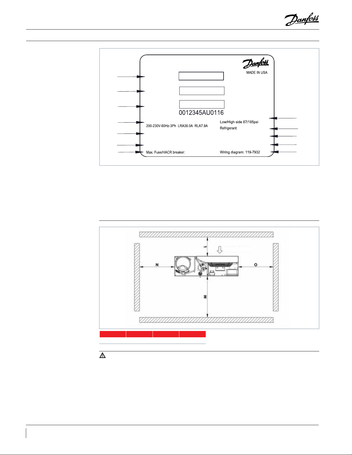
Label
Installation & Maintenance
Picture 1 : Minimum
mounting distances
A: Model and bar code
B: Unit code and bar code
C: Serial number and bar code
D: Compressor voltage & Locked rotor amps &
Rated load amps
E: Fan voltage & Full load amps
F: Min. Circuit Ampacity
L M N O
12" 26" 22" 22"
G: Max. Fuse size
H: Design pressure
I: Refrigerant
J: Oil type
K: Outdoor housing
L: Wiring diagram
AIR FLOW
IMPORTANT
2 BC251686497767en-US0801
1 - Installation and maintenance of the
condensing unit must be carried out by qualied
personnel only. Follow these instructions and best
practices on refrigeration engineering during
installation, commissioning, maintenance and
servicing tasks.
2 - The condensing unit must only be used for
its designed purposes and within its scope of
application.
3 - Under all circumstances requirements must be
fullled.
4 - The condensing unit is delivered under
nitrogen gas pressure (14.5psi) and hence
it cannot be connected as it is; refer to the
“Installation” section for further details.
5 - The condensing unit must be handled with
caution in a vertical position (maximum oset
from the vertical: 15°).
Page 3
Manual
Installation & Maintenance
Introduction
Handling and storage
IMPORTANT
These instructions pertain to OPTYMA™
condensing units (R404A, R507A, R134a, R448A,
R449A, R452A) used for refrigeration systems.
It is recommended not to open the packaging
before the unit is at the nal place for installation.
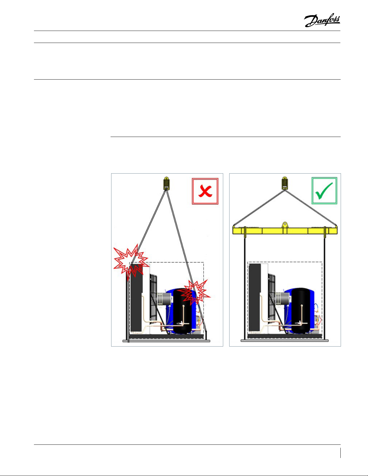
Handle the unit with care. The packaging allows
the use of a forklift or pallet jack for handling. Use
appropriate and safe lifting equipment.
• Unit must be carried out by qualied personnel
only.
• Handle the unit with caution always in a vertical
position (max. oset from the vertical: 15°).
They provide necessary information regarding
safety and proper usage of this product.
• Store and transport the unit in an upright
position.
• Store the unit between -30 °F and 120 °F.
• Don’t expose the packaging to rain or corrosive
atmosphere.
• After unpacking, check that the unit is complete
and undamaged.
• Use appropriate / safe lifting equipment. Avoid
put pressure against carton box or on any
component of the Unit.
3BC251686497767en-US0801
Page 4
Manual
Installation & Maintenance
Installation precautions
Installation
Do not braze if the condensing unit is under
pressure.
Never place the unit in a ammable
atmosphere.
Place the unit in such a way that it is not
blocking or hindering walking areas, doors,
windows or similar.
• Ensure adequate space around the unit for air
circulation and to open doors. Refer to picture 1
for minimal values of distance to walls.
• Avoid installing the unit in locations which are
daily exposed to direct sunshine for longer
periods.
• Avoid installing the unit in aggressive and/or
dusty environments.
• Ensure a foundation with horizontal surface (less
than 3° slope), strong and stable enough to carry
the entire unit weight and to eliminate vibrations
and interference.
• The unit must be securely installed on a stable
and rigid support, and x from the beginning.
• It is recommended to install the unit on rubber
grommets or vibration dampers (not supplied).
• Slowly release the nitrogen holding charge
through the Schraeder port.
• Connect the unit to the system as soon as
possible to avoid oil contamination from
ambient moisture.
• Avoid material entering into the system while
cutting tubes. Never drill holes where burrs
cannot be removed.
• The unit ambient temperature may not exceed
120 °F during o-cycle.
• Ensure that the power supply corresponds to
the unit characteristics (see nameplate).
• Use clean and dehydrated refrigeration-grade
copper tubes and silver alloy brazing material.
• Use clean and dehydrated system components.
• The suction piping connected to the compressor
must be exible in 3 dimensions to dampen
vibrations. Furthermore piping has to be done
in such a way that oil return for the compressor
is ensured and the risk of liquid slug over in
compressor is eliminated.
• Braze with great care using state-of-the-art
techniques and vent piping with nitrogen gas
ow.
• Connect the required safety and control devices.
Remove the internal valve when using the
Schraeder port for this.
• It is recommended to insulate the suction pipe
up to the compressor inlet with 3/4" mm thick
insulation.
4 BC251686497767en-US0801
Page 5
Manual
Eective Voltage R.M.S (V%)
Range
Range
10-25 ~22 psi
360˚
Installation & Maintenance
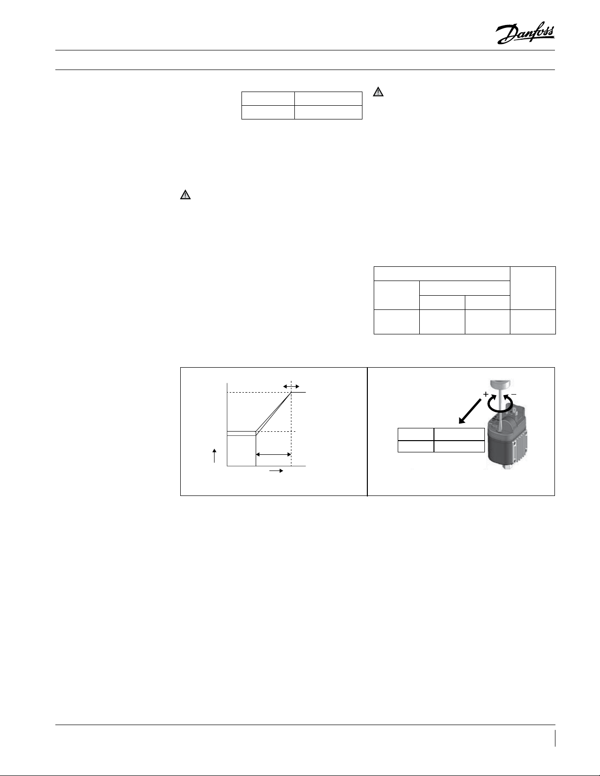
Fan speed controller
ADJUSTING
(Fig.3)
Turn the range
Catalog No. 1 Turn
XGE- 4* Approx, 22psi
Adjusting screw to clockwise (+) for increasing
the setting value, and to counterclockwise (-) for
decreasing the setting value.
(Please use the right chart as reference for
adjusting.)
CAUTION
• Do not move the screw other than the Range
Adjusting Screw.
• Do not apply torque that exceeds 0.35 Nm for
adjusting screw. Otherwise it may damage part
of resin case. Then range adjustment may not be
possible.
OPERATION CHECK
Install and calibrate the product correctly and the
check its operation to conrm correct function of
the whole system.
CAUTION
• It can not be used for ammonia refrigeration
system.
• This product is not available for the system which
apply pressure more than 681psi (47bar) because
the rated maximum working pressure of this
product is 681psi (47bar) if the pressure more
than the rated maximum working pressure is
applied to this product, it causes transformation
of characteristics or the destruction.
Operation will become unstable when using
other than sine waves for the power supply. In
this case, proper control may not be achieved.
• To ensure stable operation, sine wave AC power
supply must also be stable.
F.V.S Setting psi(bar) E.P.B.
Factory
Set
276
(19)
Adjusting Range
Min. Max.
145
(10)
363
(25)
psi
(bar)
Fixed 87
(6)
100
95
45
35
Fig.3 Fig.4
Max. Speed
50Hz at 230v
Min. Speed
E.P. B. (Fixed)
Cut O
F.V. S.
60Hz at 230v
Pressure
F.V.S.: Full Voltage Set point
The pressure at which the control delivers 95%
output eective voltage. (R.M.S.(V%))
E.P.B.: Eective Proportional Band
Range
360˚
10-25 ~22 psi
The decrease in pressure below the calibration
set point required to transmit a 45% of eective
voltage. (R.M.S.(V%))
5BC251686497767en-US0801
Page 6
Manual
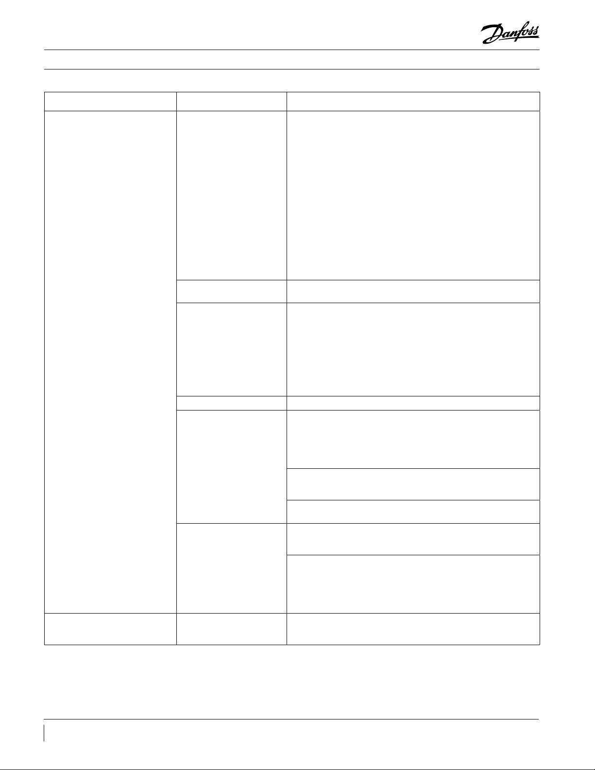
Problem Possible cause Conrmation method/Remarks
Installation & Maintenance
"F.V.S. pressure setting is
inadequate"
Check the operation of the fan motor.
• Pressure setting value may be too high if the fan motor rotates
continuously at low speed or stops.
=> Turn the F.V.S. pressure adjustment screw in (-) direction to set
the F.V.S. pressure lower.
• Pressure setting value may be too low if the fan motor rotates
continuously at full speed.
=> Turn the F.V.S. pressure adjustment screw in (+) direction to set
the F.V.S. pressure higher.
Note:
- In the event that the F. V. S. pressure setting value is lost
(for XGE-4*), rotate the pressure setting screw fully toward the
(-) symbol, then rotate it 9 times*1 towards the (+) symbol. This
should return the F.V.S. pressure setting value to around the factory
standard setting value of 1.9 MPa.
- Always conduct a test run after changing the setting to conrm
the system operates correctly.
PCB was damaged by drop
impact
Overcurrent was applied
Fan motor doesn’t rotate,
or rotates at full speed
Surge voltage was applied Check if a lightning surge or similar occurred or not.
PCB burn-out
Control is unstable.
Cannot x the plug Plug tting screw stripping
If voltage output cannot be obtained, the internal ceramic PCB may
be damaged.
Check if the rated value of the fan motor is within tolerance.
=> Max. 3A (or 4A conditionally)
• Check if a load is restricting the fan motor rotation. (Such as snow
or freezing.)
• Check if a line-to-line short circuit is detected at a connection
point of the fan motor.
• It is recommended to protect the circuit with a thermal relay or
circuit protector.
Note: Make sure to remove the cause of burn-out before
conducting a test run. Otherwise, burn-out may occur again.
Burn-out may be caused by water leakage due to an improperly
tted plug.
Check the following items to nd any problems with the tting.
• Is it tightened to the prescribed torque?
• Is the plug tted with the attached gasket?
• Is there a gap between the plug and body?
When a screw other than attached one is used, the body may be
damaged allowing water to leak inside, causing burn-out. Do not
use screws other than those attached.
Burn-out of PCB may be caused by water leaking from the
damaged part of the body.
In particular, check the connection of the pressure coupling for any
leakage. Leakage may occur when copper gasket is not used or
misaligned.
Check the pressure introduction position
• Receiver valve fully opened
• Filter drier clogged o,
• Shreader core press down.
It is recommended to detect the pressure from the exit side of
condenser.
Screws may become stripped when they are tightened with a
torque greater than the prescribed value. Please tighten with the
prescribed torque.
6 BC251686497767en-US0801
Page 7

Manual
Installation & Maintenance
Fan speed controller
bypass
Leak detection
(If FSC fails, it is possible to run the fan motor full
speed)
1. Disconnect the condensing unit from power
supply.
2. Remove wire 1 from FSC.
3. Remove wire 2 from FSC.
Fig.6
Never pressurize the circuit with oxygen or dry
air. This could cause re or explosions.
• Do not use dye for leak detection.
• Perform a leak detection test on the complete
system.
4. Connect both wires together.
5. Make sure the connection is well insulated and
not exposed to rain or in contact with, metallic
parts.
6. Connect the condensing unit back to power
supply.
• The maximum test pressure is 465psi.
• When a leak is discovered, repair the leak and
repeat the leak detection test.
Vacuum dehydration
Electrical connections
• Never use the compressor to evacuate the
system.
• Connect a vacuum pump to both the LP and HP
sides.
• Switch o the system and isolate the main power
supply.
• Ensure that power supply cannot be switched on
during installation.
• All electrical components must be selected as
per local standards and unit requirements.
• Refer to wiring diagram for electrical connections
details.
• Ensure that the power supply corresponds to the
unit characteristics and that the power supply
is stable (nominal voltage ±10 % and nominal
frequency ±2.5 Hz).
• Dimension the power supply cables according to
unit data for voltage and current.
• Protect the power supply and ensure correct
earthing.
• Pull down the system under a vacuum of 500 µm
Hg (9.7psi) absolute.
• Do not use an ohmmeter nor apply power to the
compressor while it is under vacuum as this may
cause internal damage.
• Make the power supply according to local
standards and legal requirements.
• The unit includes high and low-pressure switches
which, when activated, cut the power supply
to the compressor. Parameters for high and
low-pressure cut-outs are to be adjusted by
the installer, depending on the compressor
model, refrigerant and application. For units
with a 3-phase scroll compressor, correct phase
sequence for compressor rotation direction shall
be observed.
• Determine the phase sequence by using a phase
meter to establish the phase order of line phases
L1, L2 and L3.
• Connect line phases L1, L2 and L3 to main switch
terminals T1, T2 and T3, respectively.
7BC251686497767en-US0801
Page 8

Manual
Installation & Maintenance
Filling the system
• Wear protective stu like goggles and protective
gloves.
• Never start the compressor under vacuum. Keep
the compressor switched o.
• Before charging the refrigerant, verify that the oil
level is visible in the oil sight glass and between
25% to 75% full.
• Use only the refrigerant for which the unit is
designed for.
• Fill the refrigerant in liquid phase into the
condenser or liquid receiver. Ensure a slow
charging of the system to 58 - 70psi for R404A/
R507A or R22, and approx. 30psi for R134a.
• Do not put liquid refrigerant through the suction
line.
• It is not allow to mix additives with the oil and/or
refrigerant.
• The remaining charge is done until the
installation has reached a level of stable nominal
condition during operation.
• Never leave the lling cylinder connected to the
circuit.
Warning – Charging from
suction valve during start up can
damage the compressor.
Verication before
commissioning
Start-up
Use safety devices (such as safety pressure
switches and mechanical relief valves) in
compliance with both generally and locally
applicable regulations and safety standards. Make
sure that the devices are operational and properly
set.
Check that the settings of high-pressure
switches and relief valves don’t exceed the
maximum service pressure of any system
component.
• Never start the unit when no refrigerant is
charged.
• All service valves must be in the open position.
• Check compliance between unit and power
supply.
• Check that the crankcase heater is working.
• Check that the fan can rotate freely.
• Check that the protection sheet has been
removed from the backside of condenser.
• Balance the HP/LP pressure.
• Energize the unit. It must start promptly. If
the compressor does not start, check wiring
conformity, voltage on terminals and sequence
phase.
• Verify that all electrical connections are
properly fastened and in compliance with local
regulations.
• When a crankcase heater is required, it must be
energized at least 12 hours before initial start-up
and start-up after prolonged shut-down or belt
type crankcase heaters.
• Eventual reverse rotation of a 3-phase
compressor can be detected by the following
phenomena: unit doesn’t start, the compressor
doesn’t build up pressure, it has abnormally
high sound level and abnormally low power
consumption. In such case, shut down the unit
immediately and connect the phases to their
proper terminals.
• If the rotation direction is correct, the lowpressure gauge shall show a declining pressure
and the high-pressure gauge shall show an
increasing pressure.
8 BC251686497767en-US0801
Page 9

Manual
Installation & Maintenance
Checks with running unit
Maintenance
• Check the fan rotation direction. Air must ow
from the condenser towards the fan.
• Check current draw and voltage.
• Check suction superheat to reduce risk of
slugging.
• When a sight glass is provided, observe the oil
level at start and during operation to conrm
that the oil level remains visible.
• Respect the operating limits.
• Check all tubes for abnormal vibration.
Movements in excess of 0.06in require corrective
measures, such as tube brackets.
Always switch o the unit at main switch before
removing the fan panel.
Internal pressures and surface temperatures are
dangerous and may cause permanent injury.
Maintenance operators and installers require
appropriate skills and tools. Tubing temperature
may exceed 200 °F and therefore cause severe
burns.
Ensure that periodic service inspections to
ensure system reliability and as required by local
regulations are performed.
To prevent system related problems, following
periodic maintenance is recommended:
• Verify that safety devices are operational and
properly set.
• Ensure that the system is leak tight.
• Check the compressor current draw.
• Conrm that the system is operating in a way
consistent with previous maintenance records
and ambient conditions.
• Check that all electrical connections are still
adequately fastened.
• Keep the unit clean and verify the absence of
rust and oxidation on the unit components,
tubes and electrical connections.
• When needed, additional refrigerant in the
liquid phase may be added in the low-pressure
side as far as possible from the compressor.
The compressor must be operating during this
process.
• Do not overcharge the system.
• Never release refrigerant to the atmosphere.
• Before leaving the installation site, carry out
a general installation inspection regarding
cleanliness, noise and leak detection.
• Record type and amount of refrigerant charge,
as well as operating conditions as a reference for
future inspections.
The condenser must be checked at least once
a year for clogging and be cleaned if deemed
necessary. Access to the internal side of the
condenser takes place through the fan panel.
Microchannel coils tend to accumulate dirt on
the surface rather than inside, which makes them
easier to clean than n-&-tube coils.
• Switch o the unit at main switch before
removing any panel from the condensing unit.
• Remove surface dirt, leaves, bers, etc. with a
vacuum cleaner, equipped with a brush or other
soft attachment. Alternatively, blow compressed
air through the coil from the inside out, and
brush with a soft bristle. Do not use a wire
brush. Do not impact or scrape the coil with the
vacuum tube or air nozzle.
If the refrigerant system has been opened, the
system has to be ushed with dry air or nitrogen
to remove moisture and a new lter drier has to
be installed. If evacuation of refrigerant has to
be done, it shall be done in such a way that no
refrigerant can escape to the environment.
Maintenance
Disposal
Always transmit the model number and serial
number with any claim led regarding this
product.
The product warranty may be void in following
cases:
• Absence of nameplate.
• External modications; in particular, drilling,
welding, broken feet and shock marks.
• Compressor opened or returned unsealed.
• Rust, water or leak detection dye inside the
compressor.
Danfoss recommends that condensing
units and oil should be recycled by a
suitable company at its site.
• Use of a refrigerant or lubricant not approved by
Danfoss.
• Any deviation from recommended instructions
pertaining to installation, application or
maintenance.
• Use in mobile applications.
• Use in explosive atmospheric environment.
• No model number or serial number transmitted
with the warranty claim.
9BC251686497767en-US0801
Page 10

Manual
MBP
Dimensions
Unit
Fig. Height H [in] Width W [in] Length D [in] Suction line Liquid line
HJZM0150 1 19.5 43.5 13.4 5/8" 3/8"
HNXM0200 1 22.4 47.4 16.5 7/8" 1/2"
HNXM0250 1 22.4 47.4 16.5 7/8" 1/2"
HNXM0300 1 22.4 47.4 16.5 7/8" 1/2"
HNXM0350 1 28.2 47.4 16.5 7/8" 1/2"
HNXM0400 1 28.2 47.4 16.5 7/8" 1/2"
HRXM0500 2 28.8 49.4 31.5 7/8" 1/2"
HRXM0600 2 28.8 49.4 31.5 7/8" 1/2"
HRXM0700 2 28.8 49.4 31.5 7/8" 1/2"
HRXM0750 2 39.1 61.2 31.5 1 1/8" 5/8"
HRXM1000 2 39.1 61.2 31.5 1 1/8" 5/8"
Dimensions [in]
LBP
Unit
Fig. Height H [in] Width W [in] Length D [in] Suction line Liquid line
LJHM0150 1 19.5 43.5 13.4 5/8" 3/8"
LJHM0200 1 19.5 43.5 13.4 5/8" 3/8"
LNYM0400 1 28.2 47.4 16.5 7/8" 1/2"
LNYM0500 1 28.2 47.4 16.5 7/8" 1/2"
LRYM0600 2 28.8 49.4 31.5 1 1/8" 1/2"
LRYM0800 2 28.8 49.4 31.5 1 1/8" 1/2"
Dimensions [in]
10 BC251686497767en-US0801
Page 11

Manual
2X Knockout
7/8"
C
L
Suction Line
Liquid Line
C
L
2X Double Knockout
1-1/8" X 7/8"
W D
H
Dimensions
Figure 1
Figure 2
H
C
Suction Line
L
C
Liquid Line
L
2X Double Knockout
1-1/8" X 7/8"
2X Knockout
7/8"
W D
H
2X Knockout
7/8"
2X Double Knockout
1-1/8" X 7/8"
W
C
Suction Line
L
C
Liquid Line
L
D
11BC251686497767en-US0801
Page 12

Manual
Electrical Code N: HJZM0150, HNXM0200-0400, HRXM0500, LJHM0150-0200
Electrical wiring diagrams
Wiring Diagram 119-8312
Electrical Code Q: HNXM0200-0400, HRXM0500-1000
Wiring Diagram 119-8313
12 BC251686497767en-US0801
Page 13

Manual
Electrical wiring diagrams
Electrical Code Q: HJZM0150, LJHM0150-0200
Wiring Diagram 119-8315
Electrical Code Q: LNYM0400-0500, LRYM0600-0800
Wiring Diagram 119-8493
3
N.O. LOAD
42
1
N.C. LOAD
X
N
13BC251686497767en-US0801
Page 14

Manual
Electrical Code R: HRZM0600-1000
Electrical wiring diagrams
Wiring Diagram 119-8640
Electrical Code R: LRYM0600-0800
Wiring Diagram 119-8641
14 BC251686497767en-US0801
Page 15

Manual
Sequence of operation – Field wiring
Sequence of operation
Refrigeration Cycle 1. Defrost timer is powered by the condensing
unit, connecting the supply to terminal “1” and
“ N”.
2. The fan delay and the defrost termination
thermostat is closed in the fan delay position
and open in the defrost termination position.
The evaporator fan(s) run continuously.
3. The defrost heaters are o during refrigeration
cycle.
4. The room thermostat closes when the
temperature rises above the desired setting.
5. The liquid line solenoid valve(LSV) gets
energized and opens to allow the liquid
refrigerant to ow through the evaporator.
6. The low-pressure control switch closes when the
suction pressure rises above the cut-in setting.
7. The compressor contactor gets energized and
Defrost Cycle 1. The defrost cycle starts automatically by the
timer at predened intervals. Typical settings
are between two and four defrost cycles per day
for freezers. For heavier frost loads additional
settings may be required.
2. Contacts “2” to “4” opens in the defrost timer and
disconnects the circuit to the room thermostat,
liquid line solenoid, and evaporator fan motors.
This will lead the compressor to pump down
and shut-o. At the same time, Contacts “1”
supply power to allow the compressor and
condenser fan to run.
8. The room temperature gradually decreases to
the desired temperature.
9. Once the desired temperature is attained, the
thermostat opens and the liquid line solenoid
closes, it will in turn stop the refrigerant ow
through the evaporator.
10. Suction pressure decreases and the
compressor contactor opens when the
pressure drops below the cut-out setting on
the low-pressure control. The compressor and
condenser fan stop running.
11. This cycle is repeated as many times as
necessary to satisfy the room thermostat.
12. Frost may form on the evaporator coil until the
defrost cycle is initiated.
to “3” closes in the timer and it will allow the
defrost heater to start through the heater
contactor.
3. The defrost heaters rise the temperature of the
coil to 32˚F triggering the frost to melt of the
coil.
4. When the coil temperature rises to 45˚F to 55˚F,
the cycle limit switch closes and it energizes
the Liquid line solenoid valve to allow the
refrigeration cycle to begin again.
15BC251686497767en-US0801
Page 16

Manual
Sequence of operation – Field wiring
NOTE
Hailguard Installation
5. If the termination thermostat fails to close,
the fail-safe set on the timer will terminate the
defrost.
6. The defrost heaters are o.
7. The low-pressure control closes when the cut-in
pressure is attained, allows the compressor to
start.
This wiring diagram is for eld reference only.
1) Two contactors one for evaporator fan and
other for defrost heater will be needed. No
extra contactors to be provided with the
unit.
1. Identify the hailguard size needed and trim the
hailguard (if needed) based on the table shown
below, cutting with scissors or utility knife
Dimensions
Model
HJ X M0150 -02 0 0
LJHM0150- 0300
HJXM0200-0300 29 740 22 550
LNYM0400-0500
HJXM0350 -0400
HRXM0500-0700
LRYM0600-0800
HRXM0750-1000 58 1470 38 970
Length Height
in. mm in. mm
26 660 19 480
31 780 27 700
46 1170 28 720
8. When the evaporator coil temperature reaches
23˚F to 30˚F, the fan delay closes and allows the
fan motors to run.
9. The system will now operate in the refrigeration
cycle until another defrost cycle is triggered by
the timer.
2) Fuse F4 for defrost heaters and cable and
Fuse F5 for evaporator fans and cables will
not be supplied with the unit. These will
need to be purchased separately.
3. Lock the hailguard into place by reattaching
the screws. Start on the left side, unrolling the
hailguard before attaching to the right side. Pull
tight as you progress.
16 BC251686497767en-US0801
4. The hailguard is now attached and will protect
your Optyma Slim condensing unit from hail
and other elements.
2. Remove the screws from the sides and top of
the condenser.
Page 17

Page 18

Danfoss Commercial Compressors
Danfoss Inverter Scrolls
is a worldwide manufacturer of compressors and condensing units for refrigeration and HVAC applications. With a wide range of
high quality and innovative products we help your company to find the best possible energy efficient solution that respects the
environment and reduces total life cycle costs.
We have 40 years of experience within the development of hermetic compressors which has brought us amongst the global
leaders in our business, and positioned us as distinct variable speed technology specialists. Today we operate from engineering
and manufacturing facilities spanning across three continents.
Danfoss Turbocor Compressors
Danfoss Light Commercial Refrigeration
Disclosure: This equipment is prohibited from use in California with any refrigerants on the “List of Prohibited
Substances” for that specific end-use, in accordance with California Code of Regulations, title 17, section 95374. This
disclosure statement has been reviewed and approved by Danfoss LLC and Danfoss LLC attests, under penalty of
perjury, that these statements are true and accurate”.
Our products can be found in a variety of applications such as rooftops, chillers, residential air conditioners,
heatpumps, coldrooms, supermarkets, milk tank cooling and industrial cooling processes.
www.danfoss.us/aftermarket
BC251686497767en-US0801
Danfoss Scrolls
Danfoss Optyma Condensing Units
Danfoss Maneurop Reciprocating Compressors
Compressors
119-8385E
© Danfoss | DCS (CC) | 2019.11
 Loading...