

Page 1
Manual
Installation and maintenance
condensing unit manual
OP-HJZ / HJM / HGM / HNU / HRU / HGZ / LJZ / LGZ
http://cc.danfoss.com
Page 2

Manual
Contents
English version ....................................................................................................................4
Spanish version .................................................................................................................14
2 BC21808642813501-000201
Page 3
Model
Serial Number
Compressor:
Fan Motor:
Design Pressure:
Oil Type: Mineral
Housing for Outdoor use:
Danfoss Code
A
B
C
D
E
F
H
I
J
K
L
G
OP-HJZ018D32Q
0012345AU0116
114N3209
R22, R404A, R507A,
R134a, R448A, R449A, R452A, R513A
Manual
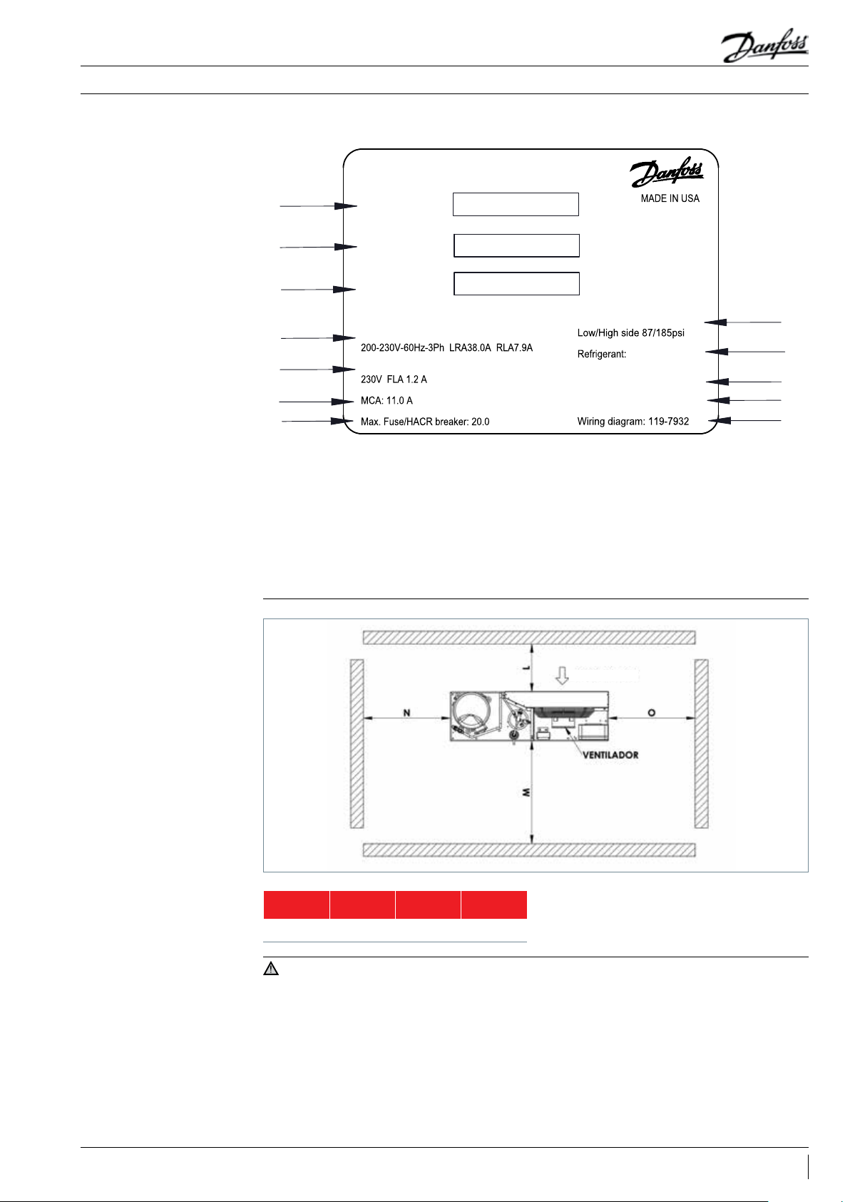
Label
Installation & Maintenance
Picture 1 : Minimum
mounting distances
A: Model and bar code
B: Unit code and bar code
C: Serial number and bar code
D: Compressor voltage & Locked rotor amps & Rated
load amps
E: Fan voltage & Full load amps
F: Min. circuit Ampacity
G: Max. Fuse size
H: Design pressure
I: Refrigerant
J: Oil type
K: Outdoor housing
L: Wiring diagram
AIR FLOW
IMPORTANT
L
[mm]
300 650 550 550
1-Installation and mainteneance of the
condensing unit must be carried out by qualified
personnel only. Follow these instructions and best
practices on refrigeration engineering during
installation, commissioning, maintenance and
servicing tasks.
2-The condensing unit must only be used for
its designed purposes and within its scope of
application.
M
[mm]
N
[mm]
O
[mm]
3 - Under all circumstances, EN 378 (or any other
applicable local safety regulation) requirements
must be fulfilled.
4 - The condensing unit is delivered under
nitrogen gas pressure (1 bar) and hence it cannot
be connected as it is; refer to the “Installation”
section for further details.
5 - The condensing unit must be handled with
caution in a vertical position (maximum offset
from the vertical: 15°).
3BC21808642813501-000201
Page 4
Manual
Installation & Maintenance
Introduction
Handling and storage
Installation precautions
These instructions pertain to OPTYMA™
condensing units (R22, R404A, R507A, R134a,
R448A, R449A, R452A, R513A) used for
• It is recommended not to open the packaging
before the unit is at the final place for installation.
• Handle the unit with care. The packaging allows
the use of a forklift or pallet jack for handling. Use
appropriate and safe lifting equipment.
• Store and transport the unit in an upright
position.
Do not braze if the condensing unit is under
pressure.
Never place the unit in a flammable
atmosphere.
Place the unit in such a way that it is not
blocking or hindering walking areas, doors,
windows or similar.
• Ensure adequate space around the unit for air
circulation and to open doors. Refer to picture 1
for minimal values of distance to walls.
• Avoid installing the unit in locations which are
daily exposed to direct sunshine for longer
periods.
• Avoid installing the unit in aggressive and/or
dusty environments.
• Ensure a foundation with horizontal surface (less
than 3° slope), strong and stable enough to carry
the entire unit weight and to eliminate vibrations
and interference.
refrigeration systems. They provide necessary
information regarding safety and proper usage of
this product.
• Store the unit between -35 °C and 50 °C.
• Don’t expose the packaging to rain or corrosive
atmosphere.
• After unpacking, check that the unit is complete
and undamaged.
• The unit ambient temperature may not exceed
50 °C during off-cycle.
• Ensure that the power supply corresponds to the
unit characteristics (see nameplate).
• When installing units for HFC refrigerants,
use equipment specifically reserved for HFC
refrigerants which was never used for CFC or
HCFC refrigerants.
• Use clean and dehydrated refrigeration-grade
copper tubes and silver alloy brazing material.
• Use clean and dehydrated system components.
• The suction piping connected to the compressor
must be flexible in 3 dimensions to dampen
vibrations. Furthermore piping has to be done
in such a way that oil return for the compressor
is ensured and the risk of liquid slug over in
compressor is eliminated.
Installation
Leak detection
Vacuum dehydration
• The unit must be securely installed on a stable
and rigid support, and fix from the beginning.
• It is recommended to install the unit on rubber
grommets or vibration dampers (not supplied).
• Slowly release the nitrogen holding charge
through the Schraeder port.
• Connect the unit to the system as soon as
possible to avoid oil contamination from
ambient moisture.
• Avoid material entering into the system while
cutting tubes. Never drill holes where burrs
cannot be removed.
Never pressurize the circuit with oxygen or dry
air. This could cause fire or explosions.
• Do not use dye for leak detection.
• Perform a leak detection test on the complete
system.
• Never use the compressor to evacuate the
system.
• Connect a vacuum pump to both the LP and HP
sides.
• Braze with great care using state-of-the-art
techniques and vent piping with nitrogen gas
flow.
• Connect the required safety and control devices.
Remove the internal valve when using the
Schraeder port for this.
• It is recommended to insulate the suction pipe
up to the compressor inlet with 19 mm thick
insulation.
• The maximum test pressure is 32 bar.
• When a leak is discovered, repair the leak and
repeat the leak detection test.
• Pull down the system under a vacuum of 500 µm
Hg (0.67 mbar) absolute.
• Do not use an ohmmeter nor apply power to the
compressor while it is under vacuum as this may
cause internal damage.
4 BC21808642813501-000201
Page 5
Manual
Installation & Maintenance
Electrical connections
Filling the system
• Switch off the system and isolate the main power
supply.
• Ensure that power supply cannot be switched on
during installation.
• All electrical components must be selected as
per local standards and unit requirements.
• Refer to wiring diagram for electrical connections
details.
• Ensure that the power supply corresponds to the
unit characteristics and that the power supply
is stable (nominal voltage ±10 % and nominal
frequency ±2.5 Hz).
• Dimension the power supply cables according to
unit data for voltage and current.
• Protect the power supply and ensure correct
earthing.
• Wear protective stuff like goggles and protective
gloves.
• Never start the compressor under vacuum. Keep
the compressor switched off.
• Before charging the refrigerant, verify that the oil
level is between “¼” and “¾” on the compressor
oil sight glass. If additional oil is required, please
refer to the compressor’s label for type of oil.
• Use only the refrigerant for which the unit is
designed for.
• Fill the refrigerant in liquid phase into the
condenser or liquid receiver. Ensure a slow
• Make the power supply according to local
standards and legal requirements.
• The unit includes high and low-pressure switches
which, when activated, cut the power supply
to the compressor. Parameters for high and
low-pressure cut-outs are to be adjusted by
the installer, depending on the compressor
model, refrigerant and application. For units
with a 3-phase scroll compressor, correct phase
sequence for compressor rotation direction shall
be observed.
• Determine the phase sequence by using a phase
meter to establish the phase order of line phases
L1, L2 and L3.
• Connect line phases L1, L2 and L3 to main switch
terminals T1, T2 and T3, respectively.
charging of the system to 4-5 bar for R22, R404A,
R507A, R448A, R449A or R452A, and approx. 2
bar for R134a or R513A.
• Do not put liquid refrigerant through the suction
line.
• It is not allow to mix additives with the oil and/or
refrigerant
• The remaining charge is done until the
installation has reached a level of stable nominal
condition during operation.
• Never leave the filling cylinder connected to the
circuit.
Verification before
commissioning
Start-up
Use safety devices (such as safety pressure
switches and mechanical relief valves) in
compliance with both generally and locally
applicable regulations and safety standards. Make
sure that the devices are operational and properly
set.
Check that the settings of high-pressure
switches and relief valves don’t exceed the
maximum service pressure of any system
component.
• Never start the unit when no refrigerant is
charged.
• All service valves must be in the open position.
• Check compliance between unit and power
supply.
• Check that the crankcase heater is working.
• Check that the fan can rotate freely.
• Check that the protection sheet has been
removed from the backside of condenser.
• Balance the HP/LP pressure.
• Energize the unit. It must start promptly. If
the compressor does not start, check wiring
conformity, voltage on terminals and sequence
phase.
• Verify that all electrical connections are
properly fastened and in compliance with local
regulations.
• When a crankcase heater is required, it must be
energized at least 12 hours before initial start-up
and start-up after prolonged shut-down or belt
type crankcase heaters.
• Eventual reverse rotation of a 3-phase
compressor can be detected by the following
phenomena: unit doesn’t start, the compressor
doesn’t build up pressure, it has abnormally
high sound level and abnormally low power
consumption. In such case, shut down the unit
immediately and connect the phases to their
proper terminals.
• If the rotation direction is correct, the lowpressure gauge shall show a declining pressure
and the high-pressure gauge shall show an
increasing pressure.
5BC21808642813501-000201
Page 6
Manual
Installation & Maintenance
Checks with running unit
Maintenance
• Check the fan rotation direction. Air must flow
from the condenser towards the fan.
• Check current draw and voltage.
• Check suction superheat to reduce risk of
slugging.
• When a sight glass is provided, observe the oil
level at start and during operation to confirm
that the oil level remains visible.
• Respect the operating limits.
• Check all tubes for abnormal vibration.
Movements in excess of 1.5 mm require
corrective measures, such as tube brackets.
• When needed, additional refrigerant in the
Always switch off the unit at main switch before
removing the fan panel.
Internal pressures and surface temperatures are
dangerous and may cause permanent injury.
Maintenance operators and installers require
appropriate skills and tools. Tubing temperature
may exceed 100 °C and therefore cause severe
burns.
Ensure that periodic service inspections to
ensure system reliability and as required by local
regulations are performed.
To prevent system related problems, following
periodic maintenance is recommended:
• Verify that safety devices are operational and
properly set.
• Ensure that the system is leak tight.
• Check the compressor current draw.
• Confirm that the system is operating in a way
consistent with previous maintenance records
and ambient conditions.
• Check that all electrical connections are still
adequately fastened.
• Keep the unit clean and verify the absence of
rust and oxidation on the unit components,
tubes and electrical connections.
liquid phase may be added in the low-pressure
side as far as possible from the compressor.
The compressor must be operating during this
process.
• Do not overcharge the system.
• Never release refrigerant to the atmosphere.
• Before leaving the installation site, carry out
a general installation inspection regarding
cleanliness, noise and leak detection.
• Record type and amount of refrigerant charge,
as well as operating conditions as a reference for
future inspections.
The condenser must be checked at least once
a year for clogging and be cleaned if deemed
necessary. Access to the internal side of the
condenser takes place through the fan panel.
Microchannel coils tend to accumulate dirt on
the surface rather than inside, which makes them
easier to clean than fin-&-tube coils.
• Switch off the unit at main switch before
removing any panel from the condensing unit.
• Remove surface dirt, leaves, fibers, etc. with a
vacuum cleaner, equipped with a brush or other
soft attachment. Alternatively, blow compressed
air through the coil from the inside out, and
brush with a soft bristle. Do not use a wire
brush. Do not impact or scrape the coil with the
vacuum tube or air nozzle.
If the refrigerant system has been opened, the
system has to be flushed with dry air or nitrogen
to remove moisture and a new filter drier has to
be installed. If evacuation of refrigerant has to
be done, it shall be done in such a way that no
refrigerant can escape to the environment.
Maintenance
Disposal
6 BC21808642813501-000201
Always transmit the model number and serial
number with any claim filed regarding this
product.
The product warranty may be void in following
cases:
• Absence of nameplate.
• External modifications; in particular, drilling,
welding, broken feet and shock marks.
• Compressor opened or returned unsealed.
• Rust, water or leak detection dye inside the
compressor.
Danfoss recommends that condensing
units and oil should be recycled by a
suitable company at its site.
• Use of a refrigerant or lubricant not approved by
Danfoss.
• Any deviation from recommended instructions
pertaining to installation, application or
maintenance.
• Use in mobile applications.
• Use in explosive atmospheric environment.
• No model number or serial number transmitted
with the warranty claim.
Page 7
Drawing 1A, version D32 (Reciprocating Compressor, 1 fan, Weiguang)
Drawing 1B, version D40 (reciprocating compressor, 1 fan, Weiguang)
Suction Line
Manual
Installation & Maintenance
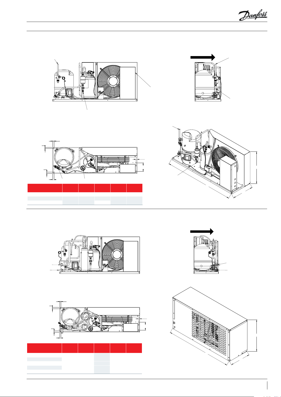
Drawing 1A, version D32 (reciprocating compressor, 1 fan)
Front View Left View
Suction Line
Liquid line
Air ow
Suction Line
Power inlet
Liquid Line
Top View
X
Fixation
X
X
Suction Line Liquid Line
X
X
[mm]Y [mm]
Height H
[mm]
Depth D
[mm]
OP-HJ … 018D-022D 16 126 463 310 1000
OP-HJ … 028D-036D
OP-HJ … 040D- 050D 688
14 174
538
420 1150
Drawing 1B, version D40 (reciprocating compressor, 1 fan)
Front View Left View
Length L
[mm]
Iso View
Suction Line
X
Y
Liquid line
L
Air ow
H
D
Liquid line
Top View
X
X
Fixation
OP-HJ … 018D-022D
OP-LJ … 048D-068D
OP-HJ … 028D-036D
OP-LJ … 108D-136D
X
X
X
[mm]Y [mm]
Height H
[mm]
Depth D
[mm]
16 126 463 310 1000
538
14 174
688
420 1150OP-HJ … 040D- 050D
Length L
[mm]
Suction Line
Liquid Line
Iso View
X
Y
H
L
D
7BC21808642813501-000201
Page 8
Drawing 2A, version D32 (reciprocating compressor, 2 fan, Weiguang)
Suction Line
Drawing 2B, version D40 (reciprocating compressor, 2 fan, Weiguang)
Manual
Installation & Maintenance
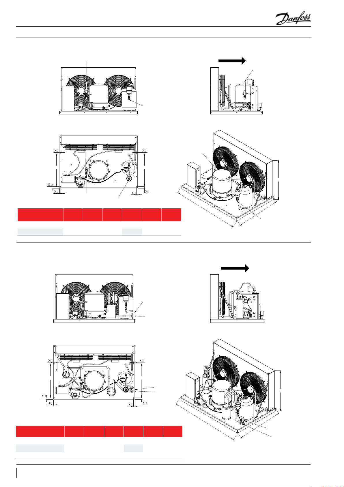
Drawing 2A, version D32 (reciprocating compressor, 2 fan)
Front View
Suction Line
Liquid Line
Top View Iso View
Y Y
Left View
Suction Line
Air ow
Suction Line
H
Suction Line
Fixation
OP-HG … 064D-100D
OP-HG … 125D-160D 971
X1
[mm]
25 20 500
Liquid Line
X2
[mm]Y [mm]
Height H
[mm]
715
Drawing 2B, version D40 (reciprocating compressor, 2 fans)
Front View
Top View Iso View
Depth D
[mm]
800 120 0
Liquid Line
Suction Line
Length L
[mm]
Left View
L
Air ow
D
Liquid Line
Y
Fixation
X1
[mm]
X2
[mm]Y [mm]
OP-HG … 064D-100D
25 20 500
OP-LG … 215D-271D 715
8 BC21808642813501-000201
Height H
[mm]
715
Y
Depth D
[mm]
800 120 0OP-HG … 125D-160D 971
Liquid Line
Suction Line
Length L
[mm]
H
L
D
Liquid Line
Page 9

Drawing 3A, version D40 (Scroll Compressor, 1 fan, Weiguang)
Suction Line
Liquid line
Drawing 3B, version D32 (Scroll Compressor, 1 fan, Weiguang)
Suction Line
Manual
Installation & Maintenance
Drawing 3A, version D40 (scroll compressor, 1 fan)
Front View Left View
Air ow
Suction Line
Liquid Line
Top View
X
X
X
X
Fixation
OP-HNU … 015D-021D
OP-HNU … 030D 688
X
[mm]Y [mm]
14 174
Drawing 3B, version D32 (scroll compressor, 1 fan)
Front View Left View
Height H
[mm]
538
Depth D
[mm]
420 1150
X
Y
Length L
[mm]
Iso View
Suction Line
Liquid Line
H
L
D
Air ow
Suction Line
Top View
X
X
X
X
Fixation
OP-HNU … 015D-021D
OP-HNU … 030D 688
Liquid line
X
[mm]Y [mm]
14 174
Height H
[mm]
538
Depth D
[mm]
420 1150
X
Y
Length L
[mm]
Iso View
Suction Line
Liquid Line
Liquid Line
H
L
D
9BC21808642813501-000201
Page 10

Drawing 4B, version D32 (Scroll Compressor, 2 fan, Weiguang)
Drawing 4A, version D40 (Scroll Compressor, 2 fan, Weiguang)
Suction Line
Manual
Installation & Maintenance
Drawing 4A, version D40 (scroll compressor, 2 fans)
Front View
Top View Iso View
Y
Fixation
OP-HRU … 038D-048D
OP-HRU … 058D-076D 971
X1
[mm]
25 20 500
X2
[mm]Y [mm]
Height H
[mm]
715
Liquid Line
Suction Line
Y
Liquid Line
Suction Line
Depth D
[mm]
800 120 0
Length L
[mm]
Left View
Air ow
H
L
D
Liquid Line
Drawing 4B, version D32 (scroll compressor, 2 fans)
Fixation
OP-HRU … 038D-048D
OP-HRU … 058D-076D 971
Front View
Suction Line
Top View Iso View
Y
Suction Line
X1
[mm]
Liquid Line
X2
[mm]Y [mm]
25 20 500
Y
Height H
[mm]
715
Liquid Line
Depth D
[mm]
800 120 0
Length L
[mm]
Left View
Suction Line
L
Liquid Line
H
D
10 BC21808642813501-000201
Page 11

MP
CH CP HP
LP
MP
Manual
Installation & Maintenance
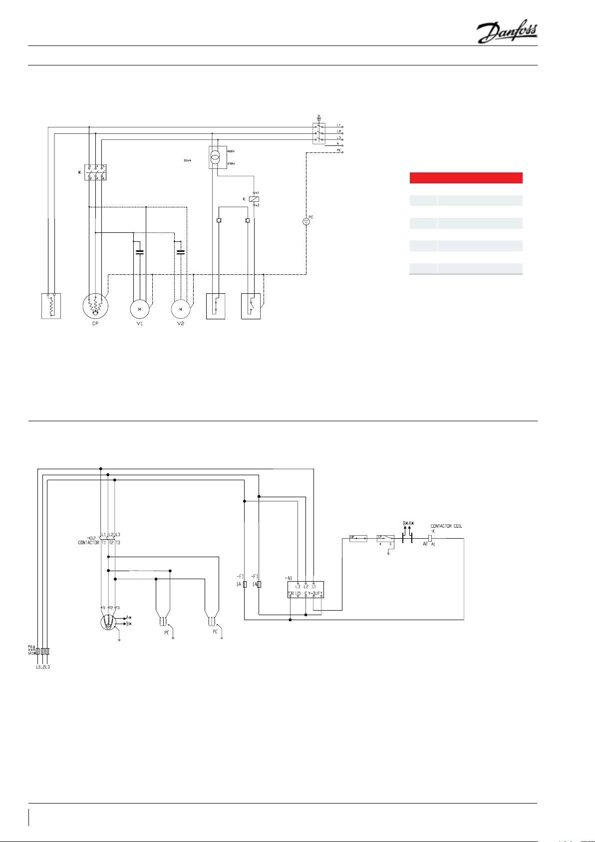
Electrical code N, 230 V/1-ph/60 Hz; units with reciprocating and scroll compressors
SC
RC
WHITE
BLACK
RED
GREEN
CH
FC
FC
BLACK
GREEN
WHITE
BROWN
WHITE
BLACK
BROWN
BLACK
GREEN
BLACK
BLACK
WHITE
GREEN
HP
LP
Legend
CP Compressor
RC Run capacitor
SC Starting capacitor
FC Fan capacitor
MP Motor protector
K Contactor
HP High-pressure switch
LP Low-pressure switch
CH Crankcase heater
RL Relay
F Fan
Electrical code Q, 230 V/3-ph/60 Hz; units with reciprocating compressors
FC
WHITE
BLACK
RED
GREEN
WHITE
FC
BROWN
WHITE
GREEN
BROWN
BLACK
BLACK
BLACK
GREEN
BLACK
BLACK
WHITE
GREEN
Legend
CP Compressor
FC Fan capacitor
MP Motor protector
K Contactor
HP High-pressure switch
LP Low-pressure switch
CH Crankcase heater
F1-F2 Fan
11BC21808642813501-000201
Page 12
MP
Manual
Installation & Maintenance
Electrical code R, 460 V/3-ph/60 Hz; units with reciprocating compressors
POWER PACK
CH
WHITE
BLACK
RED
GREEN
WHITE
CH
BLACK
WHITE
BLACK
BROWN
BLACK
GREEN
BROWN
WHITE
BLACK
BLACK
GREEN
GREEN
Legend
CP Compressor
FC Fan capacitor
MP Motor protector
K Contactor
HP High-pressure switch
LP Low-pressure switch
CH Crankcase heater
F1-F2 Fan
CH
HP LP
Electrical code Q, 230 V/3-ph/60 Hz; units with scroll compressors
WHITE
RED
BLACK
RED
WHITE
BLACK
PE
GREEN
COMPRESSORFAN 1FAN 2
BLACK
BLACK
BLACK
(OPTIONAL)
BLACK
BLACK
RED
RED
BLACK
BLACK
SEQUENCE PHASE RELAY
PRESSURE
PRESSURE
SWITCH
FROM HIGH
WHITE
RED
RED
SWITCH
FROM LOW
PE
GREEN
BLACK BLACK
POWER
12 BC21808642813501-000201
Page 13

POWER
Manual
Installation & Maintenance
Electrical code R, 460 V/3-ph/60 Hz; units with scroll compressors
RED
BLACK
WHITE
POWER PACK
BLACK
BLACK
REDRED
BLACK
PRESSURE
PRESSURE
SWITCH
FROM HIGH
RED
WHITE
SWITCH
FROM LOW
PE
GREEN
BLACK BLACK
RED
BLACK
WHITE
PE
GREEN
COMPRESSORFAN 1FAN 2
BLACK
BLACK
BLACK
(OPTIONAL)
BLACK
RED
RED
BLACK
RED
SEQUENCE PHASE RELAY
13BC21808642813501-000201
Page 14

Model
Serial Number
Compressor:
Fan Motor:
Design Pressure:
Oil Type: Mineral
Housing for Outdoor use:
Danfoss Code
A
B
C
D
E
F
H
I
J
K
L
G
OP-HJZ018D32Q
0012345AU0116
114N3209
R22, R404A, R507A,
R134a, R448A, R449A, R452A, R513A
Manual
Etiqueta
Instalación y el mantenimiento
Imagen: Distancias
minimas de instalacion
A: Modelo y codigo de barras
B: Codigo de la unidad y
codigo de barras
C: Numero de serie y codigo de barras
D: Voltaje de compresor
Amperaje de rotor bloqueado
Amperaje de carga nominal
E: Voltaje del ventilador
Amperaje a plena carga
F: Ampicidad minima del circuito
G: Tamaño maximo del fusible
H: Presion de diseño
I: Refrigerante
J: Tipo de aceite
K: Cubierta para exterior
L: Diagrama electrico
IMPORTANTE
14 FRCC.ES.013.A1.05
L
[mm]
300 650 550 550
M
[mm]
N
[mm]
1 - La instalación y el mantenimiento de la
unidad condensadora deben ser llevados a cabo
exclusivamente por personal calificado. Siga estas
instrucciones y las prácticas recomendadas en
materia de ingeniería de refrigeración durante las
actividades de instalación, puesta en servicio,
mantenimiento y servicio técnico.
2 - El uso de la unidad condensadora sólo debe
llevarse a cabo para los fines para los que ha sido
diseñada y dentro de su campo de aplicación.
3 - En cualquier circunstancia, deben cumplirse los
O
[mm]
requisitos establecidos por la norma EN 378
(o cualquier otro reglamento local vigente en
materia de seguridad).
4 - Esta unidad condensadora se suministra con
gas nitrógeno a presión (1 bar) y, por lo tanto, no
puede conectarse tal cual; consulte la sección
“Instalación” para obtener más información.
5 - Manipule la unidad condensadora con
precaución y en posición vertical (desviación
máxima respecto a la vertical: 15°).
Page 15

Manual
Instalación y el mantenimiento
Introduction
Manipulación y
almacenamiento
Medidas a adoptar de
cara a la instalación
Estas instrucciones son válidas para las unidades
condensadoras OPTYMA™ (aptas para los refrigerantes
R22, R404A, R507A, R134a, R448A, R449A, R452A, R513A),
• Se recomienda no abrir el embalaje hasta que la
unidad se encuentre en el lugar en el que se vaya
a proceder a su instalación.
• Manipule la unidad con uidado. El embalaje
admite el uso de una carretilla elevadora o una
transpaleta para su manipulación. Use siempre
equipos de elevación adecuados y seguros.
• Almacene y transporte la unidad en posición
vertical.
No realice ningún tipo de soldadura mientras la
unidad condensadora se encuentre presurizada.
No coloque nunca la unidad en una atmósfera
de carácter inflamable.
Coloque la unidad de forma que no obstruya u
obstaculice vías de paso, puertas, ventanas u otros
elementos similares.
• Asegúrese de que exista espacio suficiente
alrededor de la unidad para permitir la
circulación del aire y la apertura de las puertas.
Consulte la ilustración 1 para conocer las
distancias mínimas con respecto a las paredes.
• No instale la unidad en ubicaciones en las que
se vea expuesta a la luz solar directa a diario
durante períodos prolongados.
• No instale la unidad en atmósferas de carácter
agresivo o exceso de polvo.
• Disponga una superficie de cimentación
horizontal (con una pendiente inferior a 3°),
robusta y estable que sirva para soportar el
peso del conjunto de la unidad y eliminar las
vibraciones e interferencias.
que se utilizan en sistemas de refrigeración. Contienen
la información necesaria acerca de los aspectos de
seguridad y el uso correcto de este equipo.
• Almacene la unidad a temperaturas
comprendidas entre -35 °C y 50 °C.
• No exponga el embalaje a la lluvia o a atmósferas
de carácter corrosivo.
• Tras desembalar la unidad, compruebe que no
falte ningún componente y que no presente
daños.
• La temperatura ambiente de la unidad no debe
superar los 50 °C durante el ciclo de apagado.
• Asegúrese de que la fuente de alimentación
sea compatible con los requisitos de la unidad
(consulte la placa de características).
• La instalación de unidades destinadas al uso
con refrigerantes HFC requiere del empleo de
equipos diseñados específicamente para tales
refrigerantes y que no hayan permanecido en
contacto con refrigerantes CFC o HCFC.
• Use tubos de cobre para refrigeración limpios
y deshidratados y aleaciones de plata como
material de soldadura.
• Use componentes de sistema limpios y
deshidratados.
• La tubería de aspiración conectada al compresor
debe ser flexible en las 3 dimensiones para
amortiguar las vibraciones. Además, la tubería
debe disponerse de tal forma que el retorno de
aceite hacia el compresor esté garantizado y que
el riesgo de que se produzcan golpes de líquido
en el compresor se elimine.
Instalación
Detección de fugas
• La unidad se debe instalar de forma segura en
un soporte estable y rígido al que se deberá fijar
desde un principio.
• Se recomienda instalar la unidad sobre arandelas
de caucho o elementos que amortigüen
lasvibraciones (no se incluyen entre los
componentes suministrados).
• Libere paulatinamente la carga de nitrógeno a
través del puerto Schraeder.
• Conecte la unidad al sistema lo antes posible
para evitar que el aceite sufra contaminación
como resultado de la humedad ambiental.
No presurice el circuito con oxígeno o aire seco.
Esto podría dar lugar a incendios o explosiones.
• No use tintes para la detección de fugas.
• Lleve a cabo una prueba de detección de fugas
en todo el sistema.
• Evite que penetren materiales extraños en
el sistema durante el corte de los tubos. No
practique orificios en lugares en los que no sea
posible eliminar las rebabas.
• Lleve a cabo las soldaduras con cuidado,
empleando técnicas modernas; purgue los
conductos haciendo circular gas nitrógeno.
• Conecte los dispositivos de seguridad y control
necesarios. Retire la válvula interna cuando use
elpuerto Schraeder a este efecto.
• Se recomienda aislar la tubería de aspiración
hasta la entrada del compresor empleando
material aislante con un espesor de 19 mm.
• La presión de prueba máxima es de 32 bar.
• Si detecta una fuga, repárela y lleve a cabo una
nueva prueba de detección de fugas.
15FRCC.ES.013.A1.05
Page 16

Manual
Instalación y el mantenimiento
Deshidratación por vacío
Conexiones eléctricas
• No use el compresor para vaciar el sistema.
• Conecte una bomba de vacío a los lados LP y HP.
• Vacíe el sistema a una presión absoluta de 500
μm Hg (0,67 mbar).
• Apague el sistema y aísle la fuente de
alimentación principal.
• Asegúrese de que la fuente de alimentación no
pueda encenderse durante la instalación.
• La elección de los componentes eléctricos
debe llevarse a cabo de acuerdo con las normas
locales y los requisitos de la unidad.
• Consulte el esquema eléctrico para obtener más
información sobre las conexiones eléctricas.
• Compruebe que la fuente de alimentación sea
compatible con las características de la unidad
y que ofrezca un suministro estable (tensión
nominal ±10% y frecuencia nominal ±2,5 Hz).
• Calcule las dimensiones de los cables de la
fuente de alimentación en función de la tensión
y la corriente de la unidad.
• Proteja la fuente de alimentación y asegúrese
de que disponga de una conexión a tierra
adecuada.
• No use un ohmetro ni conecte la alimentación al
compresor mientras este se encuentre sometido
a vacío; ello podría causar daños internos.
• Conecte la fuente de alimentación de acuerdo
con las normas locales y los requisitos legales
vigentes.
• La unidad incluye presostatos de alta y baja
presión que, al activarse, cortan el suministro
eléctrico al compresor. Los parámetros de corte
para alta y baja temperatura deberán ajustarse
por el instalador dependiendo del modelo del
compresor, refrigerante y aplicación. En el caso
de las unidades con compresor scroll trifásico, se
deberá respetar la secuencia de fases correcta
a fin de que el compresor gire en el sentido
apropiado.
• Emplee un medidor de fases para establecer el
orden de las fases de línea (L1, L2 y L3).
• Conecte las fases de línea L1, L2 y L3 a los
terminales T1, T2 y T3 del interruptor principal,
respectivamente.
Llenado del Sistema
Verificación previa a la
puesta en servicio
• Utilice los equipos de protección oportunos,
como gafas y guantes de seguridad.
• No ponga en marcha el compresor en
condiciones de vacío. Mantenga el compresor
apagado.
• Antes de cargar el refrigerante, compruebe que
el nivel de aceite se encuentre entre las marcas
“¼” y “¾” del visor de aceite del compresor. Si es
necesario añadir aceite, consulte la etiqueta del
compresor para conocer el tipo de aceite que
debe emplearse.
• Utilice exclusivamente el refrigerante para el que
se haya diseñado la unidad.
• Llene el condensador o el recipiente de líquido
con refrigerante líquido. Asegúrese de que la
Emplee dispositivos de seguridad (como
presostatos de seguridad o válvulas mecánicas de
alivio) que satisfagan los requisitos de las normas
de ámbito general y local vigentes, así como las
normas de seguridad aplicables. Asegúrese de que
los dispositivos funcionen y su ajuste sea correcto.
Compruebe que los niveles de los presostatos
de alta presión y las válvulas de alivio no superen
la presión de servicio máxima de los componentes
del sistema.
carga del sistema tenga lugar paulatinamente
hasta alcanzar una presión de 4-5 bar (en el caso
de los refrigerantes R22, R404A, R507A, R448A,
R449A or R452A) o aprox. 2 bar (en el caso del
refrigerante R134a o R513A).
• No introduzca refrigerante líquido a través de la
línea de aspiración.
• Se prohíbe la mezcla de aditivos con el aceite y/o
el refrigerante.
• La carga restante se efectuará hasta que
la instalación alcance las condiciones de
funcionamiento nominales y estas se mantengan
estables.
• No deje la botella de carga conectada al circuito.
• Compruebe que todas las conexiones eléctricas
se encuentren bien fijadas y cumplan las normas
locales.
• Si es preciso el uso de una resistencia de cárter,
esta deberá activarse como mínimo 12 horas
antes de la puesta en marcha inicial y de las
puestas en marcha que se realicen tras períodos
de inactividad prolongados, así como en el caso
de las resistencias de cárter de tipo cinturón.
16 FRCC.ES.013.A1.05
Page 17

Manual
Instalación y el mantenimiento
Arranque
Comprobaciones con la
unidad en
funcionamiento
• No arranque la unidad sin haber cargado antes el
refrigerante.
• Todas las válvulas de servicio deben estar en
posición de apertura.
• Compruebe que la unidad y la fuente de
alimentación sean compatibles.
• Compruebe que la resistencia de cárter se
encuentre en funcionamiento.
• Compruebe que el ventilador pueda girar
libremente.
• Compruebe que se haya retirado la chapa
de protección de la parte posterior del
condensador.
• Equilibre las presiones de los lados HP y LP.
• Ponga en marcha la unidad. Debe arrancar
de inmediato. Si el compresor no se pone
en marcha, compruebe que los cables sean
• Compruebe el sentido de giro del ventilador.
Debe circular aire desde el condensador hacia el
ventilador.
• Compruebe el consumo de corriente y la tensión.
• Compruebe el recalentamiento en el lado de
aspiración para reducir el riesgo de generación
de golpes de líquido.
• Si la unidad incorpora un visor de líquido,
controle el nivel de aceite durante la puesta en
marcha y el funcionamiento para confirmar que
permanece dentro del rango visible.
• Respete los límites de funcionamiento.
• Compruebe si los tubos sufren alguna vibración
anormal. Los movimientos superiores a 1,5 mm
exigirán la implantación de medidas correctoras
(como la instalación de abrazaderas).
adecuados, así como la tensión en los terminales
y la secuencia de fases.
• El giro en sentido inverso de un compresor
trifásico se puede detectar a través de los
siguientes síntomas: la unidad no se pone en
marcha, no se acumula presión en el compresor,
el nivel de ruido es anormalmente alto o el
consumo de potencia es anormalmente bajo.
Si detecta alguno de dichos síntomas, detenga
a unidad de manera inmediata y conecte
correctamente las fases a sus terminales
correspondientes.
• Si la dirección de rotación es correcta, el
manómetro de baja presión deberá indicar
una disminución de la presión y el manómetro
de alta presión deberá indicar un aumento de
presión.
• Si es necesario, se puede agregar refrigerante
líquido a través del lado de baja presión (tan
lejos del compresor como sea posible). El
compresor debe permanecer en funcionamiento
durante este proceso.
• No sobrecargue el sistema.
• No libere refrigerante a la atmósfera.
• Antes de abandonar el lugar de instalación, lleve
a cabo una inspección general de la misma en
cuanto a limpieza, ruido y detección de fugas.
• Anote el tipo y la cantidad de refrigerante
cargado, así como las condiciones de
funcionamiento, como referencia para la
ejecución de futuras inspecciones.
17FRCC.ES.013.A1.05
Page 18

Manual
Instalación y el mantenimiento
Mantenimiento
Desconecte siempre la unidad utilizando el
interruptor principal antes de desmontar el panel
del ventilador.
Las presiones internas y las temperaturas
superficiales de la unidad son peligrosas y pueden
dar lugar a lesiones permanentes.
Los técnicos de mantenimiento y los
instaladores deben disponer de la formación y las
herramientas apropiadas. La temperatura de los
tubos puede superar los 100 °C, como resultado
de lo cual podrían producirse quemaduras de
carácter grave.
Asegúrese de que se realicen las inspecciones
de servicio periódicas necesarias para garantizar la
fiabilidad del sistema, de acuerdo con lo dispuesto
en la legislación local vigente.
Para evitar que se produzcan problemas
en el sistema, se recomienda llevar a cabo
periódicamente las siguientes operaciones de
mantenimiento:
• Comprobar que los dispositivos de seguridad
funcionen y su ajuste sea correcto.
• Garantizar la ausencia de fugas en el sistema.
• Comprobar el consumo de corriente del
compresor.
• Confirmar que el sistema funcione de modo
coherente con los registros de mantenimiento
anteriores y las condiciones ambientales.
• Comprobar que todas las conexiones eléctricas
se encuentren correctamente fijadas.
• Mantener limpia la unidad y comprobar
la ausencia de óxido y herrumbre en los
componentes, los tubos y las conexiones
eléctricas de la misma.
El condensador se debe revisar al menos una vez
al año para detectar posibles obstrucciones y
proceder a su limpieza, si es necesario. Se puede
acceder a la parte interna del condensador a
través del panel del ventilador. La suciedad tiende
a acumularse en la superficie de los serpentines
de los microcanales en lugar de en su interior, lo
que facilita su limpieza en comparación con los
serpentines de tubo y aletas.
• Desconecte la unidad condensadora utilizando
el interruptor principal antes de desmontar
cualquier panel de la misma.
• Elimine la suciedad, las hojas, las fibras, etc., de
las superficies empleando una aspiradora a la
que se haya acoplado un cepillo u otro accesorio
suave. También puede realizar un soplado con
aire comprimido a través del serpentín (desde su
parte interior hacia su parte exterior) y cepillarlo
con un cepillo de cerdas blandas. No use cepillos
de alambre. No golpee ni raye el serpentín con el
tubo de vacío o la boquilla de aire.
Si se ha abierto el sistema de refrigerante, este
deberá recorrerse con aire seco o nitrógeno para
eliminar la humedad; asimismo, se deberá instalar
un nuevo filtro secador. Si es necesario evacuar
el refrigerante, esta operación se deberá realizar
de manera que ninguna fracción de aquel pueda
escapar a la atmósfera.
Garantía
Eliminación
En cualquier reclamación que presente al respecto
de este producto, indique siempre el número de
modelo y el número de serie.
La garantía del producto puede quedar anulada
por los siguientes motivos:
• Ausencia de placa de características.
• Modificaciones externas; en particular,
perforaciones, soldaduras, patas rotas y marcas
de impactos.
• Apertura del compresor o devolución del mismo
sin los precintos correspondientes.
Danfoss recomienda que las unidades
condensadoras y el aceite empleado para
su funcionamiento sean reciclados por
una empresa gestora autorizada y en sus
instalaciones.
• Presencia de óxido, agua o tinte de detección de
fugas en el interior del compresor.
• Uso de un refrigerante o lubricante no
homologado por Danfoss.
• Cualquier divergencia en relación con las
instrucciones recomendadas para su instalación,
aplicación o mantenimiento.
• Uso como parte de aplicaciones móviles.
• Uso en atmósferas de carácter explosivo.
• Omisión del número de modelo o el número de
serie en la reclamación bajo garantía.
18 FRCC.ES.013.A1.05
Page 19

Drawing 1A, version D32 (Reciprocating Compressor, 1 fan, Weiguang)
H
Drawing 1B, version D40 (reciprocating compressor, 1 fan, Weiguang)
H
Manual
Instalación y el mantenimiento
Dibujo 1A - versión D32 (reciprocante hermético - 1 ventilador)
Vista frontal Vista lateral izquierda
Línea de aspiración
Entrada de
alimentación
Línea de líquido
Flujo de aire
Línea de aspiración
Línea de líquido
Vista superior
X
Fijaciones
X
X
X
Línea de aspiración
[mm]Y [mm]
X
Línea de líquido
Altura H
[mm]
Profundidad D
OP-HJ … 018D-022D 16 126 463 310 1000
OP-HJ … 028D-036D
OP-HJ … 040D- 050D 688
14 174
538
Dibujo 1B - versión D40 (reciprocante hermético - 1 ventilador)
Vista frontal Vista lateral izquierda
X
Y
[mm]
Longitud L
[mm]
420 115 0
Línea de aspiración
Vista isométrica
Línea de líquido
L
D
Flujo de aire
Línea de aspiración
Línea de líquido
Vista superior
X
X
Fijaciones
OP-HJ … 018D-022D
OP-LJ … 048D-068D
OP-HJ … 028D-036D
OP-LJ … 108D-136D
X
X
X
[mm]Y [mm]
Altura H
[mm]
Profundidad D
[mm]
Longitud L
16 126 463 310 1000
538
14 174
688
420 1150OP-HJ … 040D- 050D
[mm]
Línea de aspiración
Línea de líquido
Vista isométrica
X
Y
L
D
19FRCC.ES.013.A1.05
Page 20

Drawing 2A, version D32 (reciprocating compressor, 2 fan, Weiguang)
Drawing 2B, version D40 (reciprocating compressor, 2 fan, Weiguang)
Línea de aspiración
Manual
Instalación y el mantenimiento
Dibujo 2A - versión D32 (reciprocante hermético - 2 ventiladores)
Vista frontal
Línea de líquido
Vista superior Vista isométrica
Vista lateral izquierda
Flujo de aire
Línea de aspiración
Y
Línea de aspiración
Fijaciones
OP-HG … 064D-100D
OP-HG … 125D-160D 971
X1
[mm]
[mm]Y [mm]
25 20 500
X2
Línea de líquido
Altura H
[mm]
715
Y
Profundidad D
Dibujo 2B - versión D40 (reciprocante hermético - 2 ventiladores)
Vista frontal
Vista superior Vista isométrica
Línea de líquido
Línea de aspiración
[mm]
Longitud L
[mm]
800 120 0
Vista lateral izquierda
H
L
Flujo de aire
D
Línea de líquido
Y
Fijaciones
X1
[mm]
X2
[mm]Y [mm]
OP-HG … 064D-100D
25 20 500
OP-LG … 215D-271D 715
20 FRCC.ES.013.A1.05
Y
Altura H
[mm]
715
Línea de líquido
Línea de aspiración
Profundidad D
[mm]
800 1200OP-HG … 125D-160D 971
L
Longitud L
[mm]
D
H
Línea de líquido
Page 21

Drawing 3A, version D40 (Scroll Compressor, 1 fan, Weiguang)
H
Línea de aspiración
Drawing 3B, version D32 (Scroll Compressor, 1 fan, Weiguang)
H
Línea de aspiración
Manual
Instalación y el mantenimiento
Dibujo 3A - versión D40 (scroll - 1 ventilador)
Vista frontal Vista lateral izquierda
Línea de líquido
Vista superior
X
X
X
X
Fijaciones
OP-HNU … 015D-021D
OP-HNU … 030D 688
X
[mm]Y [mm]
14 174
Altura H
[mm]
538
Profundidad D
[mm]
420 1150
Vista isométrica
Línea de aspiración
X
Línea de líquido
Y
Longitud L
[mm]
Flujo de aire
Línea de aspiración
L
D
Dibujo 3B - versión D32 (scroll - 1 ventilador)
Vista frontal Vista lateral izquierda
Vista superior
X
X
X
X
Línea de líquido
Vista isométrica
Línea de aspiración
X
Y
Línea de líquido
Flujo de aire
Línea de aspiración
Línea de líquido
L
Fijaciones
OP-HNU … 015D-021D
OP-HNU … 030D 688
X
[mm]Y [mm]
14 174
Altura H
[mm]
538
Profundidad D
[mm]
420 1150
Longitud L
[mm]
D
21FRCC.ES.013.A1.05
Page 22

Drawing 4B, version D32 (Scroll Compressor, 2 fan, Weiguang)
Drawing 4A, version D40 (Scroll Compressor, 2 fan, Weiguang)
Línea de aspiración
Manual
Instalación y el mantenimiento
Dibujo 4A - versión D40 (scroll - 2 ventiladores)
Vista frontal
Vista superior Vista isométrica
Y
X1
Fijaciones
OP-HRU … 038D-048D
OP-HRU … 058D-076D 971
X2
[mm]
[mm]Y [mm]
25 20 500
Altura H
[mm]
715
Línea de líquido
Línea de aspiración
Y
Línea de líquido
Línea de aspiración
Profundidad D
[mm]
800 120 0
Vista lateral izquierda
Longitud L
[mm]
Flujo de aire
H
L
D
Línea de líquido
Dibujo 4B - versión D32 (scroll - 2 ventiladores)
Fijaciones
OP-HRU … 038D-048D
OP-HRU … 058D-076D 971
Vista frontal
Línea de aspiración
Vista superior Vista isométrica
Y
Línea de aspiración
Línea de líquido
X1
[mm]
X2
[mm]Y [mm]
25 20 500
Altura H
[mm]
715
Línea de líquido
Y
Profundidad D
[mm]
800 1200
Vista lateral izquierda
Línea de aspiración
Longitud L
[mm]
L
Línea de líquido
H
D
22 FRCC.ES.013.A1.05
Page 23

Manual
Instalación y el mantenimiento
Código Eléctrico N - 230V / 1F / 60Hz - Unidades con compresor reciprocante hermético y scroll
CP Compresor
CR Capacitor de marcha
CS Capacitor de partida
CV Capacitor del ventilador
GM Guardamotor
K Contactor
PH Presostato de alta
PL Presostato de baja
RC Resistencia de cárter
RL Relay
V Ventilador
Leyenda
Código Eléctrico Q - 230V / 3F / 60Hz - Unidades con compresor reciprocante hermético
Leyenda
CP Compresor
CV Capacitor del ventilador
GH Guardamotor
K Contactor
PH Presostato de alta
PL Presostato de baja
RC Resistencia de cárter
V1-V2 Ventilador
23FRCC.ES.013.A1.05
Page 24

Manual
Instalación y el mantenimiento
Código Eléctrico R - 460V / 3F / 60Hz - Unidades con compresor reciprocante hermético
Leyenda
CP Compressor
CV Capacitor del ventilador
GM Guardamotor
K Contator
PH Presostato de alta
PL Presostato de baja
RC Resistencia de cárter
V1-V2 Ventilador
Código Eléctrico Q - 230V / 3F / 60Hz - Unidades con compresor scroll
24 FRCC.ES.013.A1.05
Page 25

Manual
Código Eléctrico R - 460V / 3F / 60Hz - Unidades con compresor scroll
Instalación y el mantenimiento
25FRCC.ES.013.A1.05
Page 26
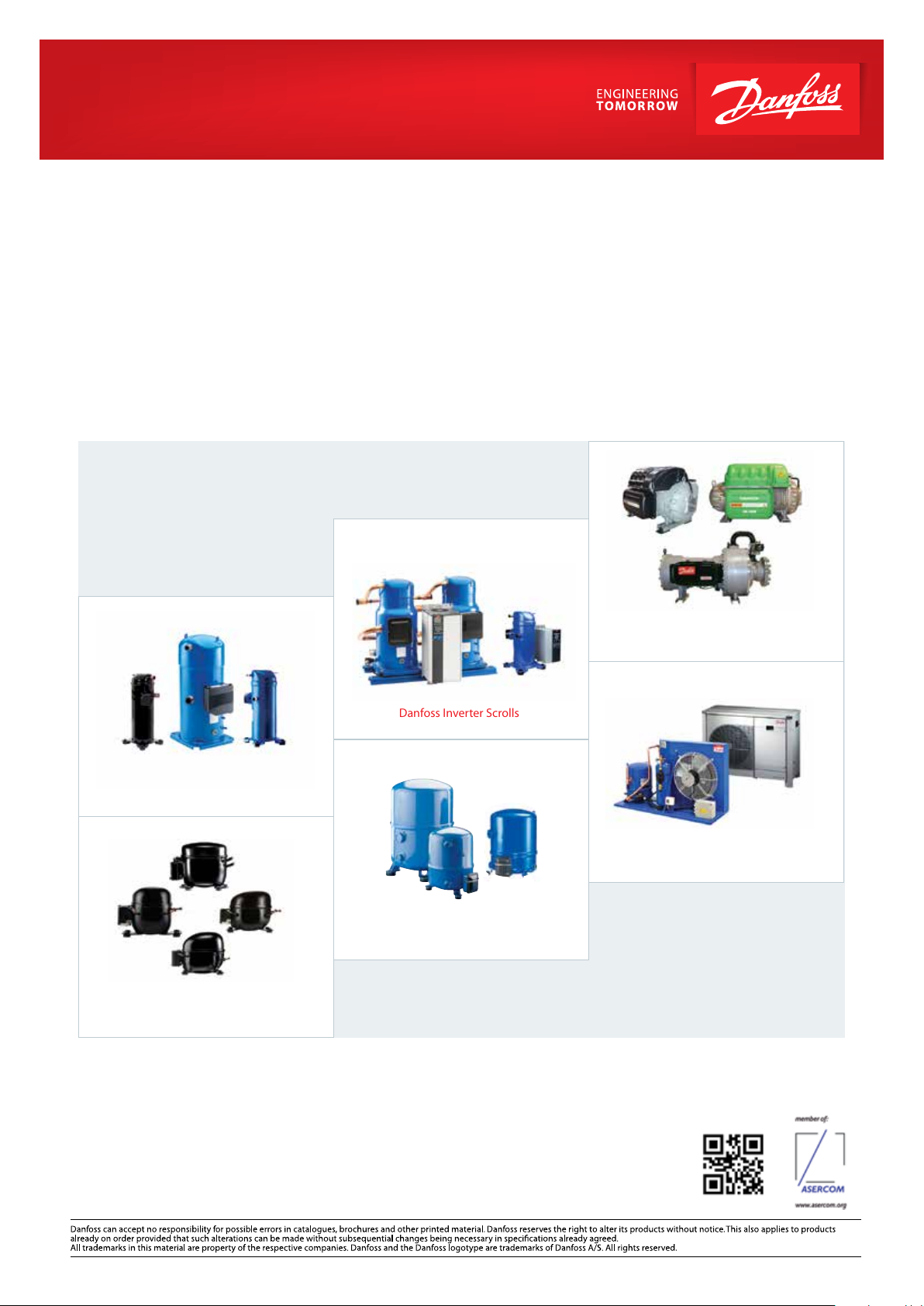
Danfoss Commercial Compressors
Danfoss Inverter Scrolls
is a worldwide manufacturer of compressors and condensing units for refrigeration and HVAC applications. With a wide range
of high quality and innovative products we help your company to find the best possible energy efficient solution that respects
the environment and reduces total life cycle costs.
We have 40 years of experience within the development of hermetic compressors which has brought us amongst the global
leaders in our business, and positioned us as distinct variable speed technology specialists. Today we operate from engineering
and manufacturing facilities spanning across three continents.
Danfoss Turbocor Compressors
Danfoss Scrolls
Danfoss Optyma Condensing Units
Danfoss Maneurop Reciprocating Compressors
Danfoss Light Commercial Refrigeration
Compressors
Our products can be found in a variety of applications such as rooftops, chillers, residential air conditioners,
heatpumps, coldrooms, supermarkets, milk tank cooling and industrial cooling processes.
http://cc.danfoss.com
Danfoss Commercial Compressors, BP 331, 01603 Trévoux Cedex, France | +334 74 00 28 29
BC21808642813501-000201
© Danfoss | DCS (CC) | 2020.01
 Loading...