

Page 1
Operating guide
OPC server for ECL Comfort 310
Table of Contents
1. Introduction to Danfoss ECL OPC Server .......................................................................................................................... 2
2. Configuring databases....................................................................................................................................................... 6
3. Exporting configuration data ............................................................................................................................................ 7
4. Importing data from an XML file ....................................................................................................................................... 8
5. Address Space .................................................................................................................................................................... 9
6. Devices .............................................................................................................................................................................. 11
7. Folders .............................................................................................................................................................................. 14
8. Data Items ......................................................................................................................................................................... 15
9. Conversions ...................................................................................................................................................................... 20
10. Device Parameters ........................................................................................................................................................... 23
11. Simulation Signals ........................................................................................................................................................... 25
12. Alarm Definitions ............................................................................................................................................................. 28
13. How the client connects to and gets data from a server ................................................................................................ 34
_______________________________________________________________________________
© Danfoss | 2016.10 VI.GU.M2.00 | 1
Page 2

Operating guide, OPC server for ECL Comfort 310
1.
The Danfoss ECL OPC Server is an OPC
serves data to OPC clients. The OPC server was implemented
using advanced programming concepts of the current
version of the OPC
generation industrial software applications.
The OPC Server communicates with OPC clients and real time
Danfoss ECL devices. This OPC server is also based on the
popular Modbus protocol and can be connected to real world
Modbus compatible I/O hardware.
Key features of the OPC Server include:
•
•
•
•
•
•
•
•
The OPC Server product contains two parts: a user interface
configuration module and the actual OPC server, the runtime
module.
Configuration module:
The
that holds configurati
name, the ranging, and the alarm settings.
The
actual values of the tags configured. Structures of both
databases are indicated in the following secti
Changes made to the configuration are accepted
restart of the OPC server. However, changes made to the
runtime database are accepted online.
_______________________________________________________________________________________
Introduction to Danfoss ECL OPC Server
-compliant server that
specification for use in developing next
Advanced OPC data quality and data conversion to
client’s request.
Supports multiple multi-drop I/O devices.
Supports multiple groups for easy configuration and
manageability.
Supports popular PLC and RTU data types.
Internally simulated for configuration and testing.
User interface for viewing tags, groups, and real-time
signals.
Supports OPC Data Access (DA) and Alarm and Events
(AE) specifications.
Flexible engineering units and signal ranges
configuration module allows you to create a database
on data of the tags such as the tag
Runtime module:
runtime module uses a runtime database to access the
_______________________________________________________________________________
© Danfoss | 2016.10 VI.GU.M2.00 | 2
ons.
only after a
Page 3
Operating guide, OPC server for ECL Comfort 310
1.1
OLE™ for Process Control (OPC) is a standards-based
approach for connecting data sources (e.g., PLCs, controllers,
I/O devices, databases, etc.) with HMI client applications
(graphics, trending, alarming, etc.).
It enhances the interface between client and server
applications by providing a universally
documented mechanism to communicate data from a data
source to any client application.
Included are not only a detailed guide on how to pass the
data, but also specific information on other attributes to
supplement those data, such as range information, data type,
quality flags, and date and time information.
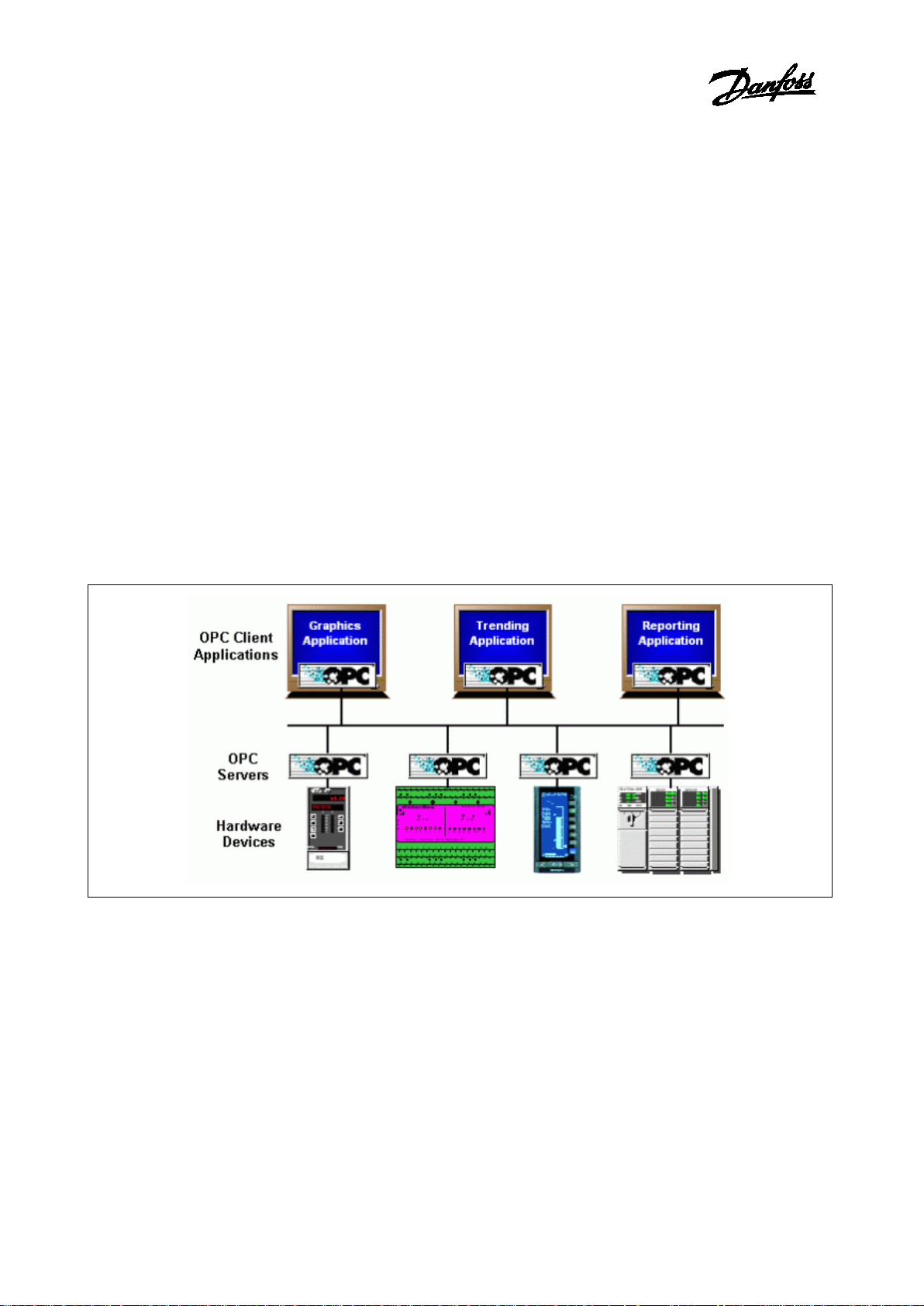
Figure 1.1 shows the OPC Architecture, which was introduced
by the OPC Foundation. By following the OPC Architecture, a
device needs only one standard driver, which is an OPC
compl
then be connected to that device, either locally or over a
network. Furthermore, connections can be made to more
than one OPC server at the same time.
Figure
Any OPC client application can connect to any OPC server. In
other words, OPC offers true Plug
fields of HMI and industrial automation. OPC server types
include OPC Data Access (DA), OPC Alarm and Events
_______________________________________________________________________________________
What is OLE for process control?
supported and well-
-
iant server. All OPC-compliant client applications can
1-1: General OPC-Based Client-Server Architecture
_______________________________________________________________________________
© Danfoss | 2016.10 VI.GU.M2.00 | 3
-and-Play capability in the
(AE).
Page 4
Operating guide, OPC server for ECL Comfort 310
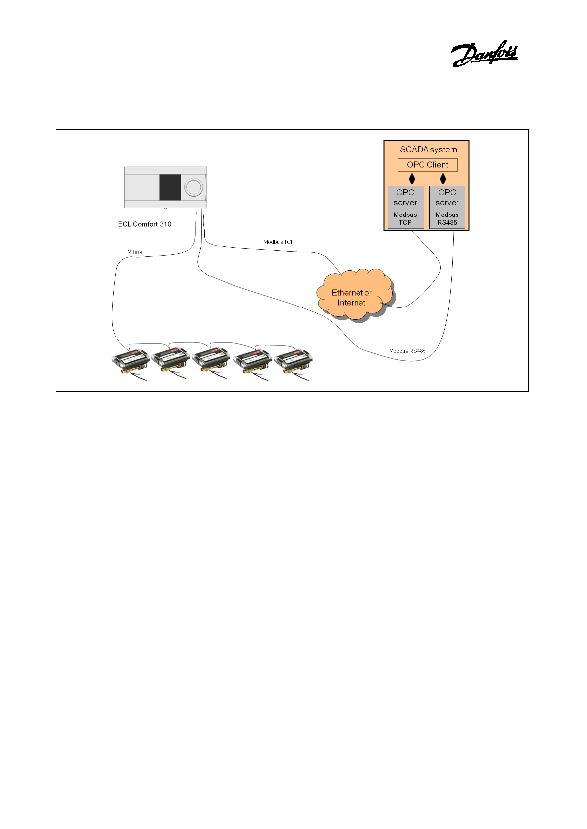
Figure
The OPC Server is based on Standard Modbus protocol for
RS485 and TCP. Heat meter data can be read through the ECL
Comfort controller
_______________________________________________________________________________________
1-2: Danfoss ECL Comfort OPC structure
using the M-bus network.
_______________________________________________________________________________
© Danfoss | 2016.10 VI.GU.M2.00 | 4
Page 5

Operating guide, OPC server for ECL Comfort 310
1.2
OPC Server Configurator can run on the following Microsoft
Windows operating systems:
•
•
•
•
•
•
•
•
•
•
•
†
Supported Editions of Windows Vista are Windows Vista
Business, Ultimate, and Enterprise Edition. Windows Vista Home
and Home Premium Editions are not supported in this release.
††
Windows 2000 is supported for Classic OPC Server installations
only.
The OPC Server Configurator is capable of running on
computer/workstation hardware with the following
specifications:
•
•
•
•
•
•
•
_______________________________________________________________________________________
System requirements
Windows Server 2008 x64 (runs in the 32 bit
compatibility mode)
Windows Server 2008
Windows Vista x64 (runs in the 32 bit compatibility
mode) †
Windows Vista †
Windows Server 2003 x64 (runs in the 32 bit
compatibility mode)
Windows Server 2003 R2
Windows Server 2003 SP2
Windows XP Professional x64 (runs in the 32 bit
compatibility mode)
Windows XP Professional SP3
Windows 2000 Server SP4 ††
Windows 2000 SP4 ††
1 GHz Processor (CPU)
1 GB Physical Memory (RAM)
2 GB Hard Disk space available
DVD drive for installation
SVGA Video Card; 256 or more colors for best results
A mouse or other compatible pointing device (such as a
trackball or touch screen)
Microsoft-compatible keyboard
_______________________________________________________________________________
© Danfoss | 2016.10 VI.GU.M2.00 | 5
Page 6

Operating guide, OPC server for ECL Comfort 310
2.
The OPC Server Configurator provides the ability to create
new
2.1
Database
To create a new Microsoft Access Configuration Database in
the
•
•
•
This configuration database will contain the configuration of
all your devices, and the logical tag naming i
address space.
2.2
Once your configuration is complete, you need to make sure
that your database is “Active”. The database that is
designated as “Active” is the one that the server uses.
To make a database active:
Sel
_______________________________________________________________________________________
Configuring databases
configuration databases.
Creating a Microsoft Access Configuration
Configurator, the following steps have to be completed:
Start the Danfoss ECL OPC Configurator.
Select ‘File’, ‘New’ from the menu and specify a name for
the configuration. For example ‘myProject.mdb’
Select the ‘Save’ button and the configuration file will be
created.
n the OPC
Activating the database
ect ‘File’, ‘Make Active’… and click the ‘Yes’ button.
_______________________________________________________________________________
© Danfoss | 2016.10 VI.GU.M2.00 | 6
Page 7

Operating guide, OPC server for ECL Comfort 310
3.
3.1
The Configurator also allows you to export data from your
configuration database to an XML file. The Configurator also
allo
XML file that specifies the data structure of an XML data file.
The purpose of having the configuration in XML would be
that you have it in another readable format and could
manipulate the content with
the changes again.
To export data, select from the menu ‘File, XML Export’…
This opens the ‘Export XML File’ dialog box. Specify a file a
name and click ‘Save’.
_______________________________________________________________________________________
Exporting configuration data
Exporting data to an XML file
ws you to export the XML schema. A schema is a special
3rd party tools to later import
_______________________________________________________________________________
© Danfoss | 2016.10 VI.GU.M2.00 | 7
Page 8

Operating guide, OPC server for ECL Comfort 310
4.
4.1
The Configurator allows you to import data from your
configuration database to an XML file.
To import data, select from the menu ‘File, XML Import’…
This opens the ‘Import XML File’ dialog box. Select a file and
click ‘Open’.
_______________________________________________________________________________________
Importing data from an XML file
Importing data from an XML file
_______________________________________________________________________________
© Danfoss | 2016.10 VI.GU.M2.00 | 8
Page 9
Operating guide, OPC server for ECL Comfort 310
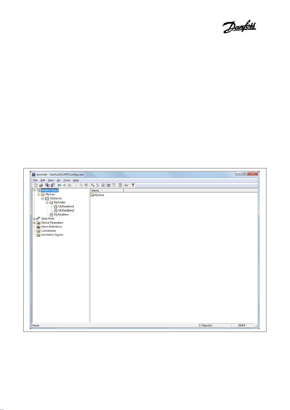
5.
The 'Address Space' branch of the Configurator provides a tree
explorer in Workbench, shown in the figure below, for setting the
properties and connection parameters of the following items:
•
•
•
Data items can be organized hierar
organizing directories and files on your computer's hard disk. The
OPC s
The Configurator module uses the terms
A folder can contain additional folders and also
data items are always the branches in the tree control hierarchy.
The hierarchical structure of the folders and data items helps to
organize the device
Figure
_______________________________________________________________________________________
Address Space
Devices
Folders
Data Items
chically. It is similar to
erver offers several levels of hierarchy.
‘Folder’ and ‘Data Item’.
data items. The
s and tags, as shown in Figure 5.1.
5.1: Address Space
_______________________________________________________________________________
© Danfoss | 2016.10 VI.GU.M2.00 | 9
Page 10
Operating guide, OPC server for ECL Comfort 310
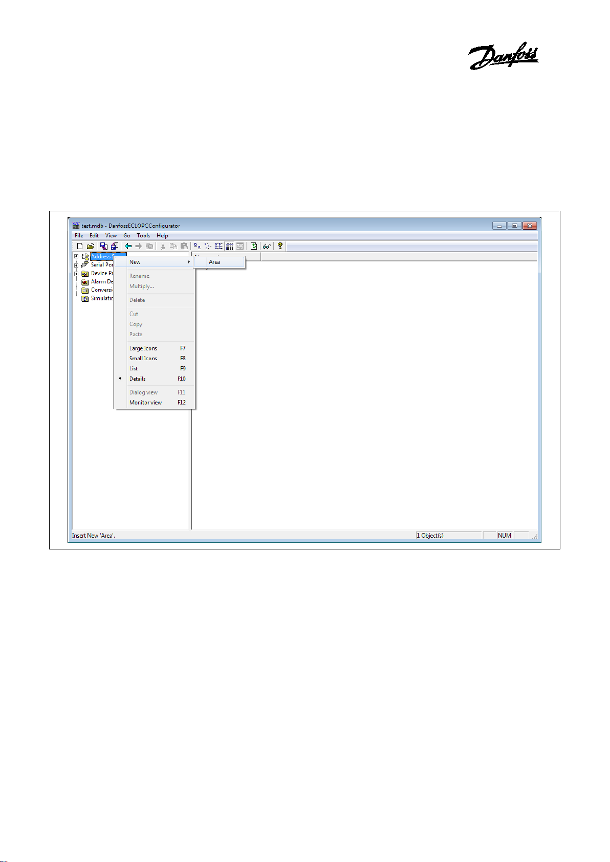
5.1
Area
as many areas as required. At least one area is required.
To add an
Right
branch in the Configurator tree
explorer in Workbench,
Figure
Or
Select the ‘Address Space’ branch in the Configurator tree
explorer in Workbench and
menu item.
_______________________________________________________________________________________
Areas
s can be used to group devices logically. You can configure
new area:
-click on the ‘Address Space’
and click on ‘New Area’.
5-2: Creating a 'New Area' in the Configurator tree explorer in Workbench
use the menu ‘Edit’, ‘New’, ‘Area’
_______________________________________________________________________________
© Danfoss | 2016.10 VI.GU.M2.00 | 10
Page 11
Operating guide, OPC server for ECL Comfort 310
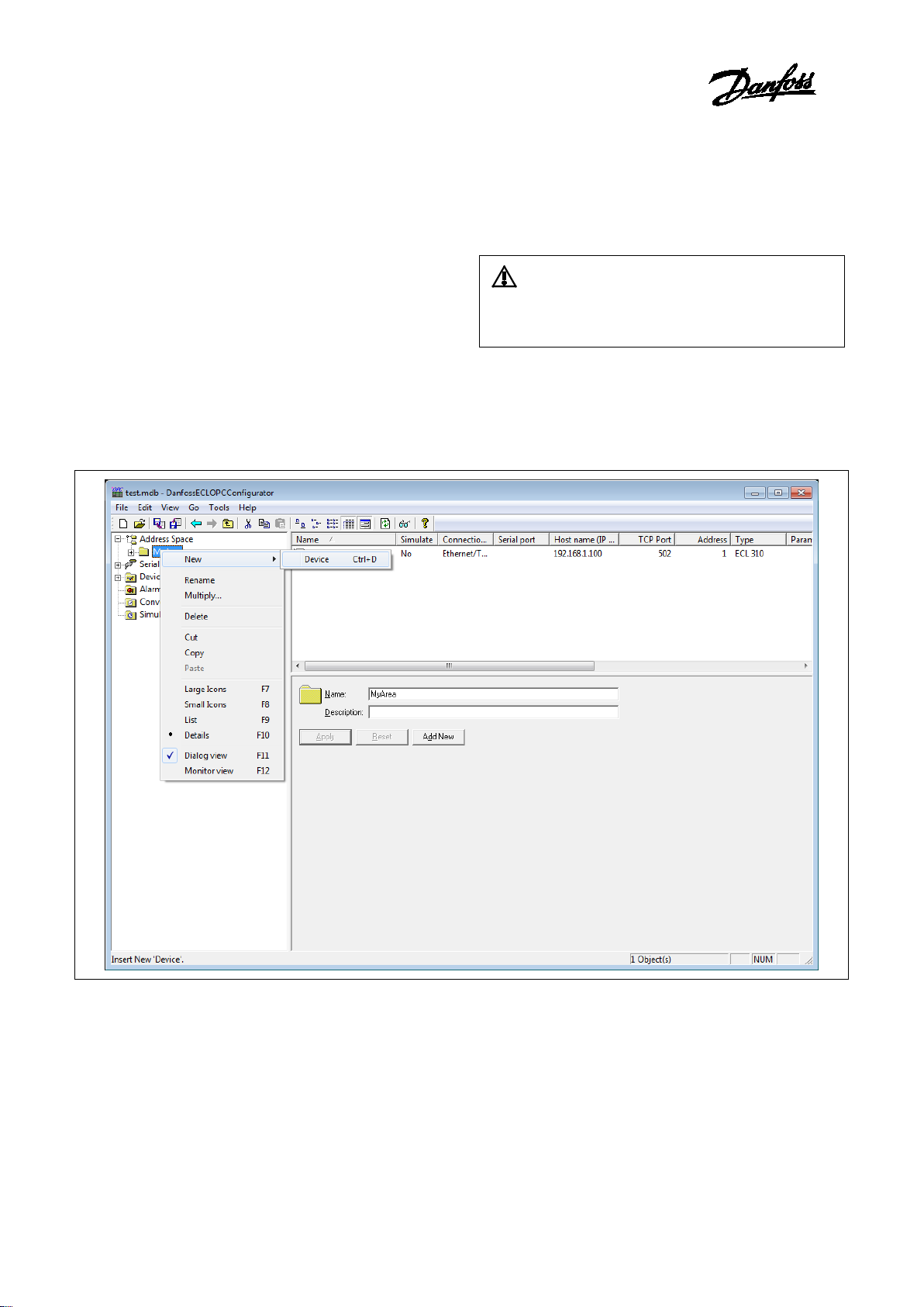
6.
In the Configurato
communicates with the OPC server over TCP/IP.
A device is directly communicating with its socket, so it is
logically under the first level in the
Again, the device is represented by its
address in combination with the unit identifier value uniquely
identifies the device.
Setting up a device requires configuring its IP address, unit
identifier, TCP port, type, timeouts and optimization parameters.
To add a devi
Right
explorer in Workbench,
Figure
Or
Select the ‘Address Space’ branch in the Configurator tree
explorer in Workbench and
menu item.
_______________________________________________________________________________________
Devices
r, a device represents a hardware device that
‘Address Space’ tree.
symbolic name. Also, its IP
ce:
-click the ‘Address Space’ branch of the Configurator tree
and click on ‘New Device’.
It is impossible to have two devices with the same IP
address.
6-1: Adding a 'New Device' in the Configurator tree explorer in Workbench
use the menu ‘Edit’, ‘New’, ‘Area’
_______________________________________________________________________________
© Danfoss | 2016.10 VI.GU.M2.00 | 11
Page 12

Operating guide, OPC server for ECL Comfort 310
Configuring devices:
Figure
Connection type:
The OPC server supports two types of data connections: Ethernet
cable and serial cable.
The best performance is achieved by using an Ethernet
connection. In this case the IP address of the device needs to be
specified as well as the TCP
I
computer connected to the device(s) needs to be selected.
Each serial port can be configured by selecting the Serial Ports
branch of the Configurator tree explorer in Workbench and set
the paramet
IP address:
The device
numbers separated by dots that indicate the location of the
device on a TCP/IP network. Each number in the address can
range from 0 to 255.
TC port:
_______________________________________________________________________________________
6-2: Configuring devices
port.
f serial connection is selected, the physical serial port of the
ers for each port.
_______________________________________________________________________________
© Danfoss | 2016.10 VI.GU.M2.00 | 12
‘IP Address’ is a 32-bit value represented as four
Page 13

Operating guide, OPC server for ECL Comfort 310
The TCP Port for Modbus communication via Ethernet is default
502 and should not be changed unless it is specifically required
by the network.
Unit Id (Identifier):
The Unit Id (Identifier) field may be used to communicate via
devices such as bridges and gateways that use a single IP address
to support multiple independent end units.
Type:
The OPC Server supports both the ECL300 and ECL310 devices.
The selected type must match the type of the device connected.
For other devices which support t
communication protocol please select the ‘Custom Type’ option.
The device parameters for ‘Simple devices’ can be configured by
selecting the ‘Device Parameters’ branch of the Configurator tree
explorer in Workbench and set the parameters
devices’.
Timeouts:
Read/Write:
Amount of time (in milliseconds) the OPC server will wait for a
response (read/write) from the device.
Timeouts to Suspend:
The number of consecutive read/write attempts that timeout
before the OPC Ser
device.
Suspend Period:
Amount of time the OPC Server will wait before attempting to
reconnect to the device.
Delay:
Amount of time (in milliseconds) between read attempts.
_______________________________________________________________________________________
he Modbus standard
for ‘Simple
ver will suspend communication with the
_______________________________________________________________________________
© Danfoss | 2016.10 VI.GU.M2.00 | 13
The Suspend Period setting can be decreased to
reconnect faster with a device that has been restarted,
but this will cause the OPC server to generate more
network traffic while a device is down.
Page 14

Operating guide, OPC server for ECL Comfort 310
7.
Folders can be used to group data items logically. You can
configure
subfolders. The OPC server supports up to three folder levels. The
use of folders is not required.
If desirable, the configuration could just contain data items
without any folders. But most likely th
application does not demand too many persistent tags
To add a
Right
Configurator tree explorer in Workbench, then click on
Folder
Figure
Creating a ‘New Folder’ in the Configurator tree explorer in
Workbench
Or
Select the ‘Device Branch’ in the Configurator tree explorer in
Workbench, then use the menu
_______________________________________________________________________________________
Folders
as many folders as required. Each folder can even have
is will only be useful if the
.
new folder:
-click on a ‘Device Branch’ (or another folder) in the
‘New
’.
7-1:
_______________________________________________________________________________
© Danfoss | 2016.10 VI.GU.M2.00 | 14
‘Edit’, ‘New’, ‘Folder’ menu item.
Page 15

Operating guide, OPC server for ECL Comfort 310
8.
A ‘Data Item’ represents a register in the device or a range of
registers. A symbolic name and description is associated with the
data item. An OPC client can obtain the data item description.
The actual OPC item name (tag) is compounded from the
‘
and the name of the data item. Data items can be located in any
folder, even in the root of the address space.
To add a
Right
Workbench
Figure
Creating a
Workbench
Or
Select the ‘Device branch’ in the Configurator tree explorer
in Workbench, then use the menu ‘Edit’, ‘New’, ‘Data
Properties for data items:
Data items have the following properties, as shown in
8
_______________________________________________________________________________________
Data Items
Address Space’ root, the names of the folder and its subfolders,
new data item:
-click a device or folder in the Configurator tree explorer in
and click on ‘New Data Item’.
8-1:
‘New Data Item’ in the Configurator tree explorer in
-2.
_______________________________________________________________________________
© Danfoss | 2016.10 VI.GU.M2.00 | 15
Item’.
Figure
Page 16

Operating guide, OPC server for ECL Comfort 310
Figure
Properties for a
Name:
A logical name for the data item (Setpoint, Param001,
ON_OFF, etc).
Description:
A
Location Type:
Location type is a type of a register in the device. Every device
is identified by its unique address. Its registers are read as
‘Input’ (1 bit long) or ‘Input Register’ (16 bits), or written t
‘Coil’ (1 bit) or ‘Holding Register’ (16 bits). Registers of each
type are addressed by using 16
are divided into ‘Coils’, ‘Inputs’, ‘Input Registers’ and ‘Holding
Registers’. Table 3
Read Only
Read/Write
1 bit
Input
Coil
16 bit
Input Register
Holding Register
Table 3
Name conventions
Modbus Type:
The location type (device data) will be understood as Modbus
type (OPC data type). Modbus data type also depends on the
‘
The ‘Data Length’ (bytes) field tells you how long (in bytes) the
When selecting the Modbus STRING type, you must
_______________________________________________________________________________________
8-2:
‘Data Item’
descriptive comment for the data item.
-bit numbers. Device registers
-1 explains the name conventions used.
Location type’ selected.
_______________________________________________________________________________
© Danfoss | 2016.10 VI.GU.M2.00 | 16
o as
-1:
Example:
‘Coil’ or ‘Input’ (1 bit) device data type can be Modbus
BOOL only.
Page 17

Operating guide, OPC server for ECL Comfort 310
field is for the Modbus type (e.g. ‘REAL’, ‘INT’, ‘UINT’, etc.)
selected. The ‘BOOL’ length is always 1 bit.
specify the data length (how many bytes will the STRING
Simulation:
To test the client functionality, choose a ‘Simulation Signal’
from the ‘Signal’ drop
checkbox. See the ‘Simulation Signals’ section for information
about creating simulation signals.
All levels in the ‘Address Space’ (port, device, folder, data item)
support the process of simulation (Simulate checkbox). The
parent list in the tree is superior; it has a higher priority when
deciding to simulate the data item or not.
In other words, a data item is simulated, if it itself has a
simulation selected, or if any of its parents has the ‘Simulate’
checkbox checked. (
checkbox stays unchecked.)
Manual Value:
If the ‘Simulate’ checkbox is checked, the data item will offer a
constant parameter value, because the ‘Manual Value ‘setting
is of the highest priority. The changes in the configuration take
effect only when the server reloads the configuration (on
startup).
Starting Address:
This value specifies the data item address (register number) in
the device data space. With the 'UINT' Modbus type, it is
possible to
Boolean or integer value (this functionality is read
You can specify a group of 'Count' adjacent bits inside a word
starting with 'Bit #'. This way, it is possible to use a register for
several sepa
Use Conversion:
To get the data value converted according to a prescribed
form, choose one of the predefined or user
conversions. See the conversions section for more details.
Generate Alarm:
Check the ‘Generate Ala
generate alarms based on the data item value. The ‘Msg.
prefix’ parameter is the text of the message for this data item.
It will be followed by the text configured for a particular alarm
type. The second part of the alarm me
‘Message Body’ string (see ‘Alarm Definitions’).
The server allows any number of predefined alarm definitions
(templates). You can combine one of them with the specific
tags.
_______________________________________________________________________________________
-down list and check the ‘Simulate’
It may be simulated even if its ‘Simulate’
be represented by).
extract bits from the register and use them as a
rate data items.
-defined
rm’ checkbox to make the server
ssage will contain the
_______________________________________________________________________________
© Danfoss | 2016.10 VI.GU.M2.00 | 17
-only).
Page 18

Operating guide, OPC server for ECL Comfort 310
Additional Properties:
Clicking the ‘Additional
‘Additional Properties’ dialog box, shown in Figure
allows you to set a textual string for an Open/Close label, a
default display, a .bmp file, an HTML file, a sound file, and an
.avi file.
These properties are also
clients. For example, to see the HTML file name being
presented in the OPC client, you should append .HTMLFile to
the OPC Item name.
Figure
‘Additional Properties’ dialog box
Importing XML-file with ‘Data Items’ for ECL device
The OPC Server comes with an XML
configurations and descriptions for all ‘Data Items’ supported
by the ECL device. By importing this XML
are ready for use by the OPC Server or may option
modified to fit specific requirements.
To import XML-file with ‘Data Items’:
Select a Device in the Configurator tree explorer in Workbench
and click on the ‘Import XML’ button.
_______________________________________________________________________________________
Properties’ button opens the
8-3, which
accessible for OPC Data Access
8-3:
-file containing names,
-file all ‘Data Items’
ally be
It is recommended to import the XML-file for the
application used by the ECL Controller to ease the
configuration of its parameters.
_______________________________________________________________________________
© Danfoss | 2016.10 VI.GU.M2.00 | 18
Page 19

Operating guide, OPC server for ECL Comfort 310
Figure
Importing the XML
Select the appropriate ECL device and application key and
click the OK button to import the XM
Figure
Import ECL310 data
_______________________________________________________________________________________
8-4:
-file with ‘Data Items’ in Workbench
L-file:
8-5:
_______________________________________________________________________________
© Danfoss | 2016.10 VI.GU.M2.00 | 19
Page 20

Operating guide, OPC server for ECL Comfort 310
9.
You can tell the server to convert device data value simply by
setting the Conversion properties, as shown in figure
To add a new conversion
Right
explorer in Workbench, then click on ‘New Conversion’.
Figure
Adding a
Workbench
Or
Select the Conversion branch in the Configurator tree explorer
in
This opens the Conversions properties window in the right
pane of Workbench. Configure the following properties as
specified below.
_______________________________________________________________________________________
Conversions
9-1.
-click the Conversions branch of the Configurator tree
9-1:
‘New Conversion’ in the Configurator tree explorer in
Workbench, then use the menu ‘Edit’, ‘New’, ‘Conversion’.
_______________________________________________________________________________
© Danfoss | 2016.10 VI.GU.M2.00 | 20
-
Page 21

Operating guide, OPC server for ECL Comfort 310
Figure
Name:
Specifies the name of the conversion definition. The name can
be up to 12 alphanumeric characters, including underscores
( _ ) and hyphens (
Conversion type:
For each conversion definition, select one of the following
conversion types from the dro
•
•
•
Conversion parameters:
•
•
_______________________________________________________________________________________
9-2: Conversion properties
- ).
p-down list:
None (make float): Converts the data into float data type,
but does not change the value itself. When this option is
selected, the ‘Engineering Units’ and ‘Instrument Range’
fields are disabled.
Linear: Keeps a linear relation between EU and IR.
Square Root: Keeps a square root relation between EU and
IR.
Engineering Units (EU): Client scale; specify low and high
values for the engineering units (if applicable).
Instrument Range (IR): Device scale; specify low and high
values for the instrument range (if applicable).
_______________________________________________________________________________
© Danfoss | 2016.10 VI.GU.M2.00 | 21
Page 22

Operating guide, OPC server for ECL Comfort 310
Clamping:
If clamping is enabled, the data value will be limited to its
‘High Value/EU High Value’ when it exceeds the upper limit,
and similarly to its ‘Low Value/Low EU Value’ parameter when
it exceed
clamping types from the drop
•
•
•
Clamping Parameters:
Specify low and high values for the clamping range.
_______________________________________________________________________________________
s the bottom limit. Select one of the following
-down list:
None: No clamping type is specified.
Clamp on EU: Clamps on the specified low and high
engineering units (EU) values.
As Specified: Clamps on a specified range (set within the
Clamping parameters section of the window) of low and
high values.
_______________________________________________________________________________
© Danfoss | 2016.10 VI.GU.M2.00 | 22
Page 23

Operating guide, OPC server for ECL Comfort 310
10.
To
Right
Con
Parameter’.
Figure
Creating a
e
Or
Select the Device Parameters branch of the Configurator tree
explorer in Wor
‘
This opens the
right-pane of Workbench. Configure the following properties
as specified in Figure
_______________________________________________________________________________________
Device Parameters
add a new device parameter:
-click the ‘Device Parameters’ branch of the
figurator tree explorer, and click on ‘New Device
10-1:
‘New Device Parameter’ in the Configurator tree
xplorer in Workbench
kbench, and use the menu ‘Edit’, ‘New’,
Device Parameter’ menu item.
‘Device Parameters’ properties window in the
10-2.
_______________________________________________________________________________
© Danfoss | 2016.10 VI.GU.M2.00 | 23
Page 24

Operating guide, OPC server for ECL Comfort 310
Figure
Device Param
Every device is identified by its unique address. Its registers
are read as Input (1 bit long) or Input Register (16 bits), or
written to as Coil (1 bit) or Holding Register (16 bits). Registers
of each type are addressed by using 16
The meaning of numbers in the device parameters dialog,
shown in the figure above, is the maximum amount of data
that can be transferred in one message. Setting the value
equal to 0 (zero) forces the server to use single read/write
messages o
You can also configure the following additional properties for
each device type
Word swap:
Swaps the first word with the second when reading/writing
DINT, UDINT or float values. Word swapping is checked by
default to make it consistent with th
multi
Swap bits:
Reverses the order of bits in word
significant bit becomes the most significant bit).
_______________________________________________________________________________________
10-2:
eter Properties
nly.
-byte variables.
-bit numbers.
e DVT way of storing
-sized values (least
_______________________________________________________________________________
© Danfoss | 2016.10 VI.GU.M2.00 | 24
Page 25

Operating guide, OPC server for ECL Comfort 310
11.
The Configurator offers various OPC data items in the
‘
functionality, choose a simulation signal from the tree
explorer. All levels in the ‘
process of simulation. The parent list in the tree explorer is
superior. It has higher
data item or not.
To add a new simulation signal:
Right
tree explorer, and click on ‘
Figure
Creating a ‘New Simulati
e
Or
Select the Simulation Signals branch of the Configurator tree
explorer in Workbench, then use the menu
‘
This opens the
right
parameters as specified
_______________________________________________________________________________________
Simulation Signals
Simulation Signals’ tree control. To test the client
Address Space’ folder support the
priority when deciding to simulate the
-click the Simulation Signals branch of the Configurator
New Simulation Signal’.
11-1:
on Signal’ in the Configurator tree
xplorer in Workbench
‘Edit’, ‘New’,
Simulation Signal’ menu item.
-pane of Workbench. Configure the following
_______________________________________________________________________________
© Danfoss | 2016.10 VI.GU.M2.00 | 25
‘Simulation Signal Parameters’ window in the
in Figure 11-2.
Page 26

Operating guide, OPC server for ECL Comfort 310
Figure
Each ‘Simulation Signal’ type has specific parameters, as
shown below.
Name:
Sp
name can be up to 12 alphanumeric characters, including
underscores ( _ ) and hyphens (
Type:
For each signal, you can select one of the following signal
types from the
•
•
•
•
specifies the signal frequency
moves the signal origin on
_______________________________________________________________________________________
11-2:
Simulation Signal Parameters
ecifies the name of the selected simulation signal. The
drop-down list:
Read Count is incremented by one every time when the
item is read.
Write Count increments when the item is written.
Random generates random value within the ‘Amplitude’
range starting with ‘Position’.
Ramp’, ‘Sine’, ‘Square’, ‘Triangle’ and ‘Step’ are periodical
signals. Their time behavior is influenced by ‘Period’ and
‘Phase’ parameters. ‘Period’
(in milliseconds), while ‘Phase’
the time axis (in degrees).
- ).
_______________________________________________________________________________
© Danfoss | 2016.10 VI.GU.M2.00 | 26
Page 27

Operating guide, OPC server for ECL Comfort 310
Parameters:
•
•
amplitude will be divided.
_______________________________________________________________________________________
‘Square’ and ‘Triangle’ have one additional parameter:
‘Ratio’. Ratio defines Triangle signal steepness, or Square
signal H/L proportions.
The ‘Number of Steps’ parameter of the ‘Step’ signal
defines the number of steps into which the signal
_______________________________________________________________________________
© Danfoss | 2016.10 VI.GU.M2.00 | 27
Page 28

Operating guide, OPC server for ECL Comfort 310
12.
The OPC Server is an OPC Alarm and Events server that
supports the following alarm types:
•
• Digital Alarms
Alarm parameters are set up in the Configurator under the
‘
which is divided into two alarm template types: ‘
A
‘
only, while
except for the ‘String’
provided in the sample configuration database.
12.1
To add a
Right
tree explorer, then
Figure
Creating a
e
_______________________________________________________________________________________
Alarm Definitions
Limit (High High, High, Low, Low Low)
Alarm Definitions’ tree control, shown in the figure below,
Digital
larm’ definitions and ‘Limit (analog) Alarm’ definitions.
Digital Alarms’ can be defined for a data item of "BOOL" type
‘Limit Alarms’ can be defined for all other types
data type. Default alarm definitions are
Limit Alarms
new limit alarm definition:
-click the ‘Alarm Definitions’ branch of the Configurator
click on ‘New Limit Alarm Definition’.
11-1:
‘New Limit Alarm Definition’ in the Configurator tree
xplorer in Workbench
_______________________________________________________________________________
© Danfoss | 2016.10 VI.GU.M2.00 | 28
Page 29

Operating guide, OPC server for ECL Comfort 310
Or
Select the ‘Alarm Definitions’ branch of the Server
Configurator tree explorer in Workbench,
‘Edit’, ‘New’, ‘Limit Alarm Definition’ menu item.
This opens the ‘Limit Alarm Definition’ properties window in
the right
Figure
Limit Alarm Definition
A limit alarm sets the values for four levels of alarms: ‘LoLo’,
‘Lo, Hi’,
subranges within the data item amplitude. Every subrange
definition includes a ‘
that will be appended to
the alarm message, the ‘
Ack.’
In the ‘
dialog box configure
the following settings:
Name:
In the ‘
_______________________________________________________________________________________
then use the menu
-pane of Workbench.
12-2:
and ‘HiHi’. Limit alarm parameters can have
Message Body’
Severity’ of the alarm, and the ‘Req.
flag for alarm acknowledgement.
Limit Alarm Definition Properties’
Name’ field, type a name for the new limit alarm.
_______________________________________________________________________________
© Danfoss | 2016.10 VI.GU.M2.00 | 29
Page 30

Operating guide, OPC server for ECL Comfort 310
Update Rate:
‘Update Rate’
item value (in milliseconds), and possibly responding by
sending the alarm message.
Deadband:
‘Deadband’
amount of alarm messages and overloading the clients when
the signal oscillates around one of t
deadband value extends the limit zone. It results in sending
only one alarm message even if the signal oscillates.
Deadband indicates the deadband value to apply to the
converted analog values. The deadband value is required and
i
repeated alarm cycles.
Value :
The ‘
fields. For example, a value of 10 for ‘LoLo’ is compared with
the value of the input to determine
state.
Message body:
In the ‘
will appear when the alarm is sent. The message can be any
text string.
Return to Normal.
In the ‘
enter the text that will appear when the alarm is taken care of
(e.g. has been acknowledged). The message can be any text
string.
post a description of LoLo limit.
Severity:
‘
defined value for alarm Priority. The valid
OPC severity range is 0 (lowest) to 1000 (highest).
Requires Ack:
The ‘Requires Ack’ field is used for OPC condition alarms to
determine whether the alarm needs a user
acknowledgement. If the ‘Requires Ack’ field is checked, then
the alarm requires a user acknowledgement. If the value is
not checked,
acknowledged
any values specified in configuration mode.
_______________________________________________________________________________________
defines the frequency of checking the data
prevents the server from generating a huge
he limits specified. The
s calculated on borderline alarming limit values to prevent
Value’ field is used to calculate the state of the input
if the alarm is in ‘LoLo’
Message Body’ field, enter the warning message that
Return to Normal’ field, check the check box and then
Severity’ is the OPC-
then the alarm is posted as already
.
_______________________________________________________________________________
© Danfoss | 2016.10 VI.GU.M2.00 | 30
It is not necessary to enter a message text or a base text.
The Server will default to the OPC subcondition name and
the OPC condition name. For example, a LoLo alarm will
Changes to the alarm property fields (HiHi, LoLo, Hi, Lo,
Message Text, etc.) in runtime through an OPC tag update
will be automatically saved to the database, over-writing
Page 31

Operating guide, OPC server for ECL Comfort 310
12.2
To add a
Right
Configurator tree explorer, then click on
Alarm Definition
Figure
Creating a
tree explorer in Workbench
Or
Select the 'Alarm Definitions' branch of the Configurator tree
explorer in Workbench, then use the menu ‘Edit’, ‘New’, ‘Digital
Alarm Definition’ menu item.
_______________________________________________________________________________________
Digital alarms
new digital alarm definition:
-click the 'Alarm Definitions' branch of the
‘New Digital
’.
12-3:
‘New Digital Alarm Definition’ in the Configurator
_______________________________________________________________________________
© Danfoss | 2016.10 VI.GU.M2.00 | 31
Page 32

Operating guide, OPC server for ECL Comfort 310
This opens the ‘Digital Alarm Definition’ properties window in the
right
Figure
Digital Alarm Definition
Specify a ‘Value’ for the digital alarm (‘True’ or ‘False’).
Message Body:
In the ‘Message Body’ field, enter the warning mes
appear when the alarm is sent. The message can be any text
string.
Return to Normal:
In the ‘Return to Normal’ field, check the check box and then enter
the text that will appear when the alarm is taken care of (e.g. has
been acknowl
Severity:
‘Severity’ is the OPC
y. The valid OPC
severity range is 0 (lowest) to 1000 (highest).
_______________________________________________________________________________________
-pane of Workbench.
12-4:
edged). The message can be any text string.
-defined value for alarm Priorit
_______________________________________________________________________________
© Danfoss | 2016.10 VI.GU.M2.00 | 32
sage that will
It is not necessary to enter a message text or a base text.
The server will default to the OPC subcondition name
and the OPC condition name.
Page 33

Operating guide, OPC server for ECL Comfort 310
Requires Ack:
The ‘Requires Ack’ field is used for OPC condition alarms to
determine whether the alarm needs a user acknowledgement.
Apply:
‘Apply’: Saves all changes specified in the pro
The alarm definition appears in the tree control.
_______________________________________________________________________________________
perties dialog box.
_______________________________________________________________________________
© Danfoss | 2016.10 VI.GU.M2.00 | 33
Page 34

Operating guide, OPC server for ECL Comfort 310
13.
a server
When OPC servers are installed on the system, they are registered
so that clients can find them and users can view th
make a client/server connection, the user must first choose a
server. The server name selected is used to get a class ID which, in
turn, is used to create a COM object. If the user selects a server
that is not currently running, the system starts the server and then
creates the object in that server on behalf of the client.
Once the COM object is created, the client application has an
IOPCServer interface, as defined in the OPC specification. This is
the main interface to an OPC server, and
this as the Server interface. (The other interface is Group.) An OPC
client always creates a group in the server and registers an advice
interface with it to get asynchronous data notification.
When an item is added, the dialog dis
flat list of names, depending on the server. The names are queried
from the Server object using the filter string and requested data
type. When the user either types or selects a name, an item by that
name is added to the Grou
immediately to get an initial value.
Items in a group are scanned by the server; when their values
change, the advise interface in the client is notified. A data
structure containing the data for each item whose value or qu
has changed (and only those items) is passed to the client’s advice
interface. The client unpacks and uses the data.
13.1
The server status dialog periodically queries the server object for
status and displ
The ‘Group Parameters’ dialog box queries the group state and
displays the results. The ‘OK’ button and ‘Apply’ button in the
‘Group Parameters’ dialog box write the parameters from the
dialog to the Group object and read the parameters b
primarily controls the scanning and updating of data. When a
group is inactive, it does not send data notifications to the client
and, typically there is no reason to scan the items when the group
is inactive.
The ‘Update Rate’ in the ‘Group Par
the rate at which data notifications should be sent back to the
client, assuming that data have changed. This is also the rate at
which items are scanned on behalf of this client.
_______________________________________________________________________________________
How the client connects to and gets data from
em in a list. To
this document refers to
plays either a hierarchy or a
p object. This item is also read
Server status and group parameters
ays the results.
_______________________________________________________________________________
© Danfoss | 2016.10 VI.GU.M2.00 | 34
ameters’ dialog box specifies
ality
ack. This
Page 35

Operating guide, OPC server for ECL Comfort 310
13.2
The OPC server is the actual runtime module. The OPC server is
responsible for accessing the data on the OPC clients' requests.
The OPC server has no user interface. It will be started
automatically when the OPC client connects to the server.
The runtime module
and write operations are performed directly with no intermediate
cache level. It has the effect that every client works with accurate
data. In normal situations, the data in the database will be
accessed (read/write) by OPC clients. However, the data are stored
in a standard database, and other software applications can
manipulate its data as well through programming techniques
such as Microsoft's ADO (ActiveX Data Objects) or OLE DB. The
OPC Server refreshes (with
to inform the OPC clients of changes through some external
application.
One of the basic concepts of the OPC server is that monitored data
are relatively stable in time. The runtime module resides in the
Danfoss/Danf
_______________________________________________________________________________________
Danfoss ECL Runtime Module
operates directly with the database. Read
a configurable delay) its tags in order
oss ECL OPC server directory.
_______________________________________________________________________________
© Danfoss | 2016.10 VI.GU.M2.00 | 35
 Loading...