

Page 1
Data Sheet
Check valve
Type NRVT
For high pressure CO2 application
NRVT piston type check valves is designed for
installation in discharge line to prevent
refrigerant migration to protect compressor
and enable the pressure equalization of rotary
compressor before startup. In the meanwhile
this valve can be used in other installation
positions of CO2 systems such as hot gas and
suction lines.
Features:
• Stable operation covering full map of
compressor
• Fullls high temperature and pressure
requirements for the discharge lines used in
Transcritical CO2 systems
◦ Rupture proof, optimized TIG welding
◦ Specially-selected sealing material for CO
refrigerant
• Hermetic brass body design
• Compatible to connect both copper/stainless
steel tubes
• In compliance to PED & UL regulations
2
AI405623214680en-000101
Page 2
GC
CCMT Light
CCMT Light
AKVP
AKVP
NRVT
NRVT
EVT
EVT
Check valve, type NRVT
Applications
Typical applications for NRVT valves are:
• CO2 MiniPack
• CO2 CDU BLDC
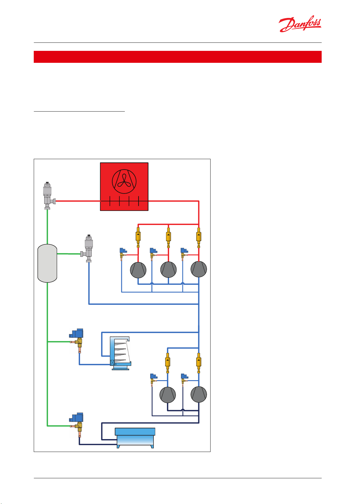
Pressure Equalization/ Relief
• To start rotary BLDC compressors, it is necessary to equilize pressure between discharge and suction line.
• In single compressor solution it is possible to manage equalization via high pressure valve and bypass valve
• In system with parallel mounted compressors, It is necessary to install on each compressor check valve in
discharge line and solenoid valve to bypass high pressure to suction line
Figure 1: Pressure Equalization/ Relief
© Danfoss | Climate Solutions | 2022.02 AI405623214680en-000101 | 2
Page 3
GC
CCMT
CCMT
NRVT
NRVT
NRVT
AKVP
AKVP
Check valve, type NRVT
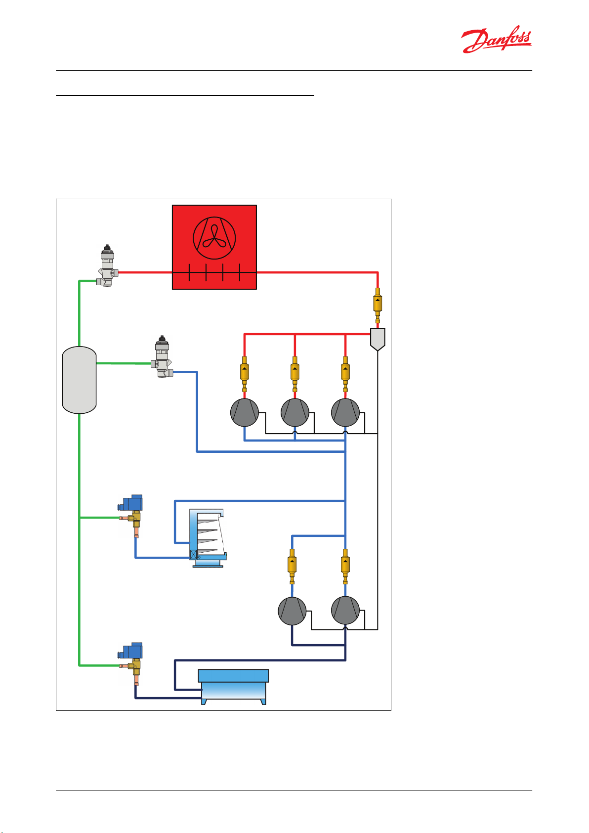
Discharge line – compressors mounted in parallel
• If using an individual oil separator for each compressor – for protection against back condensation of
refrigerantin the separator with the compressor shut-o.
• If the cylinder heads of the compressors can cool down below the condensing temperature at standstill
• Check valve for a common oil separator (installation position towards the condenser):
– If there is a danger of back condensation from the condenser or liquid receiver
– Systems with long shut-o periods
Figure 2: A diagram of Discharge line – compressors mounted in parallel
© Danfoss | Climate Solutions | 2022.02 AI405623214680en-000101 | 3
Page 4
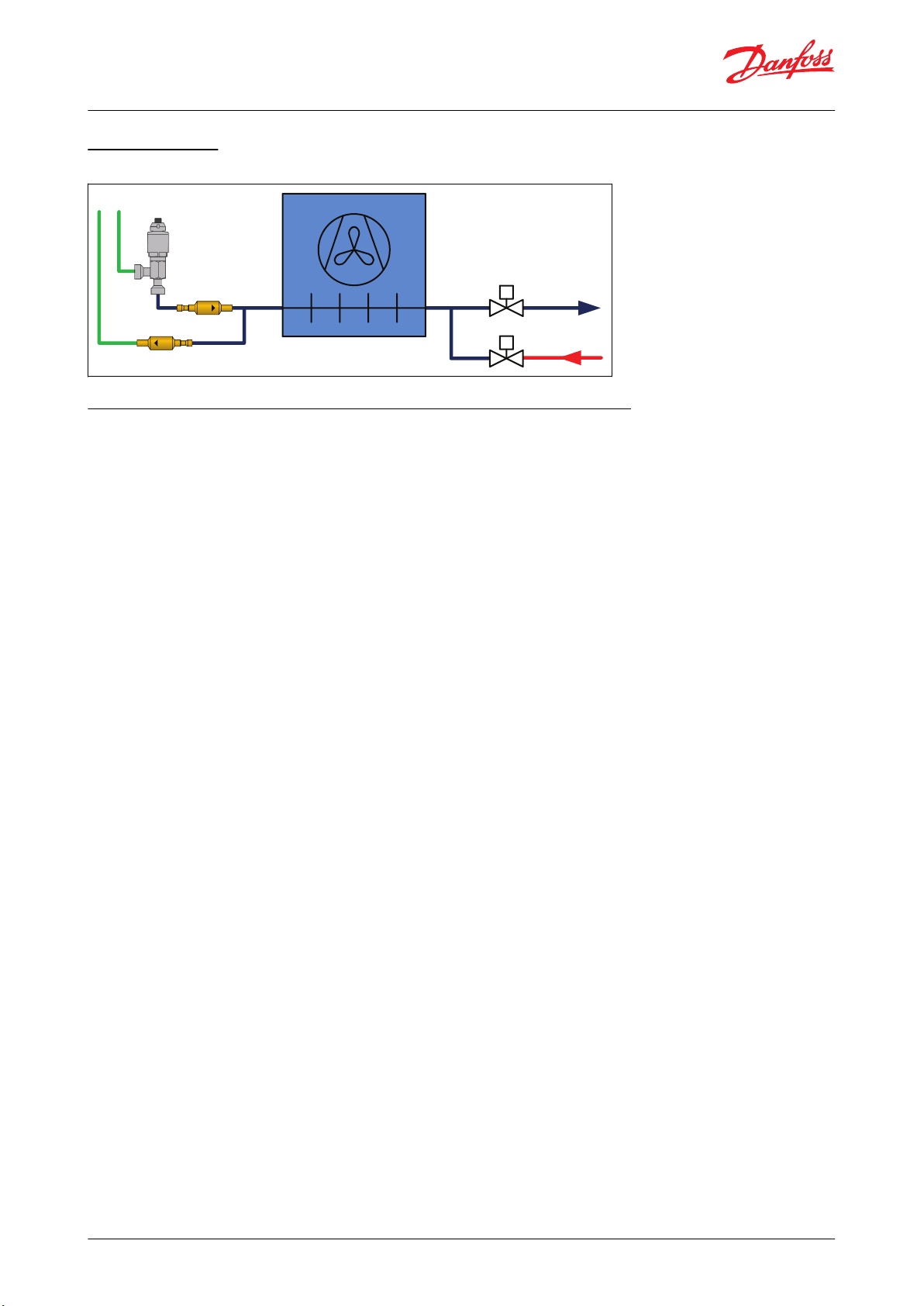
Liquid line
Suction line
Hot Gas line
Defrost drain line
Check valve, type NRVT
Hot Gas Defrost
Figure 3: A diagram of Hot Gas Defrost
Low Pressure lift Multi Ejector / cold & warm ambient temperature
Optimal solution for smaller commercial refrigeration systems
• In colder ambient conditions system operates as a standard booster system
• Ejector is simply controlling the high pressure as a high pressure valve according to the optimal COP Gas Cooler
pressure algorithm
• Pressure in the receiver as pressure dierence between the receiver and Po-MT evaporator suction pressure
• Receiver pressure controlled by rst gas by-pass valve CCMT#1, second gas by-pass valve CCMT#2 is closed
• Check valve on MT evaporator suction line is open
• In warmer ambient conditions temperature out of the gas cooler is high and corresponding optimal pressure in
gas cooler is high too, so ejector can lift all gas mass ow from MT evaporators through the ejector to the
receiver
• Check valve in suction line between compressors and MT evaporators is closed due to pressure dierence
• The pressure in the receiver is result of the ejector performance.
• Both gas by-pass valves CCMT#1 & CCMT#2 are open to minimize pressure loses
• MT compressors are controlled based on Po-MT pressure sensor and Psuc-MT is protection
© Danfoss | Climate Solutions | 2022.02 AI405623214680en-000101 | 4
Page 5

MT
LT
Psuc-MT
Po-MT
GC
CTM 6 LP
NRVT
CCMT#1
CCMT#2
Check valve, type NRVT
Figure 4: Low Pressure lift Multi Ejector / cold & warm ambient temperature
© Danfoss | Climate Solutions | 2022.02 AI405623214680en-000101 | 5
Page 6

Technical data
Values
Refrigerants
R 744 (CO2)
Refrigerant oil
POE, PAG
Max. working pressure
140 bar / 2031 psig
Media temperature range
-40 °C – 150 °C / -40 °F – 302 °F
Flow direction
Single-ow
Valve direction
Sraightway
Serviceable
non-serviceable
Product engraving
Packaging label
M
a
d
e
i
n
U
S
A
020-6411
M
R
3
0
0
7
2
1
/
S
NRVT
TS/COT-40C TO 150C
PS 140BARDP/MAP2031PSIG
Information
Explanation
Danfoss
Danfoss Logo
NRVT
Product type
020-6411
Code number for ordering
PS 140 BAR DP/MAP 2031 PSIG
Max. working pressure
TS/COT -40°C TO +150°C
Media temperature range
MR
Place of manufacture
300721/S
Production date: DDMMYY/S (S: shift)
MADE IN USA
Country of origin
UL and EAC logos
Approval
Information
Explanation
Check valve
Product Description
NRVT
Product type
020-6411
Code number
R744
Refrigerant
Straightway
Direction
DN 3/8 in ODF
Connection
PS 140bar/MWP 2031psig
Max Working Pressure
Check valve, type NRVT
Product specication
Technical data
Table 1: Technical data
Identication
Relevant product data is available on the product and box label. An example of a box label and product label are
shown, including an explanation of the content.
Table 2: Box label & product label (example)
Table 3: Product engraving
Table 4: Packaging label
© Danfoss | Climate Solutions | 2022.02 AI405623214680en-000101 | 6
Page 7

Information
Explanation
TS -40/+150°C -40/302°F
Media temperature range
MR
Place of manufacture
110122
Production date: DDMMYY
MADE IN USA
County of origin
Data Matrix
Content of traceability data matrix code (IDKey)
EAN code
Barcode for individual code no. identication according to EAN standard
Danfoss A/S, 6430 Nordborg, Denmark
Address
1
5
4
6
2
3
Position
Description
Material
1
Valve body
Brass2Piston
Brass3Spring
Stainless steel
4
Piston guide
Brass5Stop face
Brass6Tailpiece
Brass
Check valve, type NRVT
Design and materials
The pressure of the uid passing through a refrigeration system opens the valve, while any reverse ow closes the
valve.
In NRVT check valve a sealing disc is activated by the spring to close or open the valve, and the force of the spring
determines the Min. opening pressure. When the refrigerant ows through the valve and the dierential pressure of
the ow is higher than the Min. opening pressure, the piston will move towards the stop face and compress the
spring, then the valve will open.
Figure 5: Design and materials
Dimensions and Weights
You will nd downloadable dimension drawings for individual code numbers on Danfoss store as part of the Visuals
tab for individual code numbers.
© Danfoss | Climate Solutions | 2022.02 AI405623214680en-000101 | 7
Page 8

D
L
L1
L1
Danfoss
64G8052
Type
Connection Size
Connection tol‐
erance
LL1øD
Net weight
Code no.
[in.]
[mm]
[mm]
[mm]
[mm]
[mm]
[kg]
NRVT 10s
3/8
-
-0.76/+0.76
110.5
8.6
26.4
0.2
020-6401
NRVT 10sH
0.35
020-6411
NRVT 12s
1/2-110.5
10.4
26.4
0.2
020-6402
NRVT 12sH
0.35
020-6412
NRVT 16s
5/8-132.1
12.7
34.9
0.35
020-6403
*
NRVT 16sH
0.35
020-6413
*
Check valve, type NRVT
Figure 6: Dimensions and Weights
NOTE:
(*) 5/8 in. will be available in July, 2022
© Danfoss | Climate Solutions | 2022.02 AI405623214680en-000101 | 8
Page 9

Valve type
Multi pack
Code no.
Solder ODF × ODF
Kv
Cv
Min. OPD Δp
Max.
working
pres‐
sure:
PS/MWP
Media temperature
range
PED cat‐
egory
Start open
Fully open
[in.]
[mm]
[m3/h]
[gal/min]
[bar]
[psi]
[bar]
[psi]
NRVT 10s
020-6401
3/8 1.20
1.39
0.01
0.15
0.05
0.73
140 bar /
2031 psig
-40 °C – 150 °C / -40
°F –302 °F
Art. 4.3
NRVT 12s
020-6402
1/2 2.10
2.44
NRVT 16s
020-6403*
5/8 4.80
5.57
NRVT 10sH
020-6411
3/8 1.20
1.39
0.25
3.63
0.9
13.05
NRVT 12sH
020-6412
1/2 2.10
2.44
NRVT 16sH
020-6413*
5/8 3.50
4.06
Check valve, type NRVT
Ordering
Table 5: Ordering
NOTE:
(*) 5/8 in. will be available in July, 2022
© Danfoss | Climate Solutions | 2022.02 AI405623214680en-000101 | 9
Page 10

File name
Document type
Document topic
Approval authority
EAC Declaration
EAC
EAC RU
033F4003
Manufacturers Declaration
PED
Danfoss
033F4006
Manufacturers Declaration
China RoHS
Danfoss
033F4010
Manufacturers Declaration
RoHS
Danfoss
Mechanical - Safety Certicate
UL
UL
Check valve, type NRVT
Certicates, declarations, and approvals
The list contains all certicates, declarations, and approvals for this product type. Individual code number may have
some or all of these approvals, and certain local approvals may not appear on the list.
Some approvals may change over time. You can check the most current status at danfoss.com or contact your local
Danfoss representative if you have any questions.
Certicates, declarations, and approvals
Table 6: Certicates, declarations, and approvals
© Danfoss | Climate Solutions | 2022.02 AI405623214680en-000101 | 10
Page 11

Online support
Danfoss oers a wide range of support along with our products, including digital product information, software,
mobile apps, and expert guidance. See the possibilities below.
The Danfoss Product Store
The Danfoss Product Store is your one-stop shop for everything product related—no matter where
you are in the world or what area of the cooling industry you work in. Get quick access to essential
information like product specs, code numbers, technical documentation, certications, accessories,
and more.
Start browsing at store.danfoss.com.
Find technical documentation
Find the technical documentation you need to get your project up and running. Get direct access to
our ocial collection of data sheets, certicates and declarations, manuals and guides, 3D models
and drawings, case stories, brochures, and much more.
Start searching now at www.danfoss.com/en/service-and-support/documentation.
Danfoss Learning
Danfoss Learning is a free online learning platform. It features courses and materials specically
designed to help engineers, installers, service technicians, and wholesalers better understand the
products, applications, industry topics, and trends that will help you do your job better.
Create your Danfoss Learning account for free at www.danfoss.com/en/service-and-support/learning.
Get local information and support
Local Danfoss websites are the main sources for help and information about our company and
products. Find product availability, get the latest regional news, or connect with a nearby expert—all
in your own language.
Find your local Danfoss website here: www.danfoss.com/en/choose-region.
Coolselector®2 - nd the best components for you HVAC/R system
Coolselector®2 makes it easy for engineers, consultants, and designers to nd and order the best
components for refrigeration and air conditioning systems. Run calculations based on your operating
conditions and then choose the best setup for your system design.
Download Coolselector®2 for free at coolselector.danfoss.com.
Any information, including, but not limited to information on selection of product, its application or use, product design, weight, dimensions, capacity or any other
technical data in product manuals, catalogues descriptions, advertisements, etc. and whether made available in writing, orally, electronically, online or via download,
shall be considered informative, and is only binding if and to the extent, explicit reference is made in a quotation or order conrmation. Danfoss cannot accept any
responsibility for possible errors in catalogues, brochures, videos and other material. Danfoss reserves the right to alter its products without notice. This also applies to
products ordered but not delivered provided that such alterations can be made without changes to form, t or function of the product. All trademarks in this material
are property of Danfoss A/S or Danfoss group companies. Danfoss and the Danfoss logo are trademarks of Danfoss A/S. All rights reserved.
© Danfoss | Climate Solutions | 2022.02 AI405623214680en-000101 | 11
 Loading...