

Page 1
NF9.5FK
105G
5929
NF9.5FK
8398-7
DANFOSS COMPRESSORS
Barcode on
white background
Green background
Blue stripe
Application
R134a
SUCTION
CONNECTOR
Compressors
Standard Compressor
R134a
115-127V 60Hz
Data Sheet (Replaces CG.43.W2.22)
General
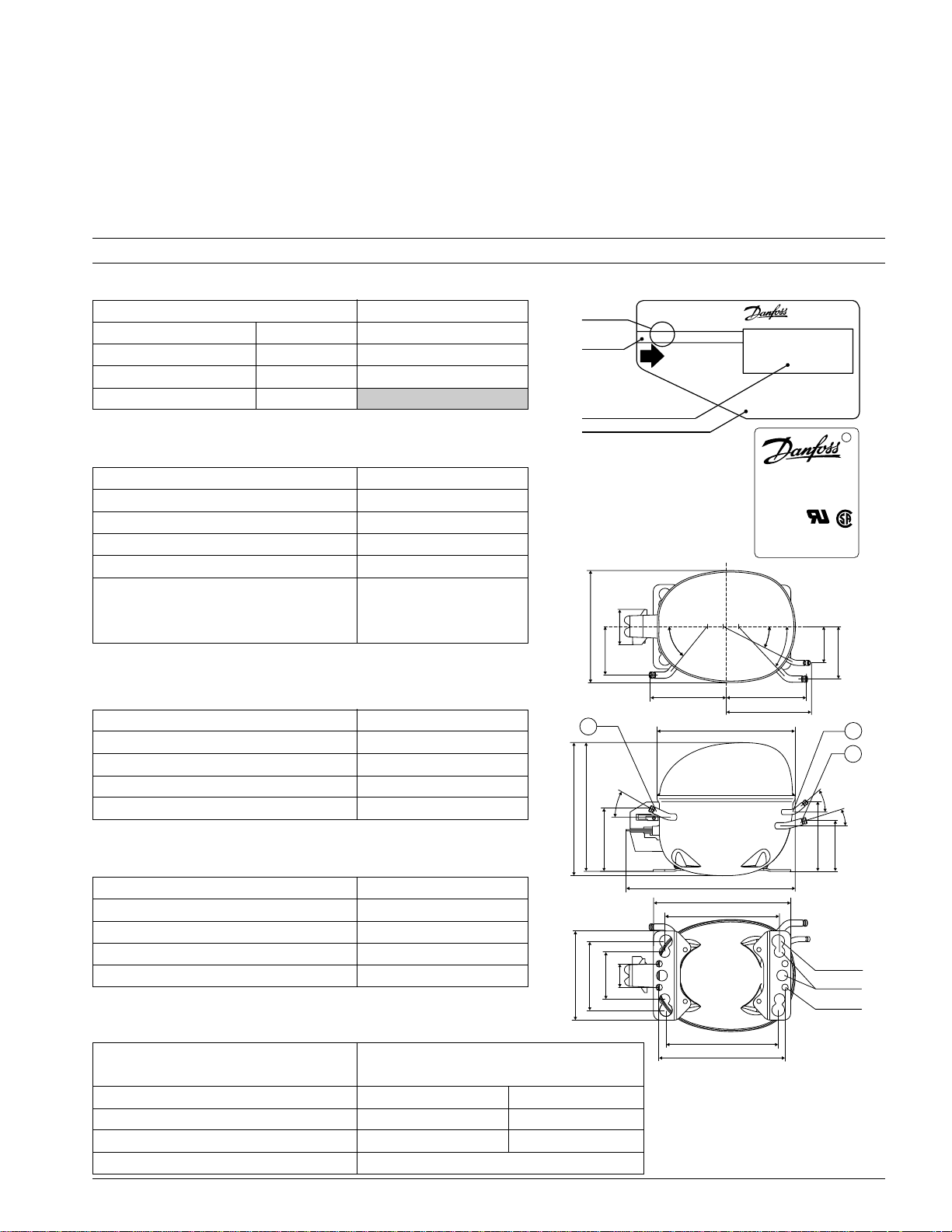
Compressor NF9.5FK
Connector-material Sealing Code number
Copper-plated steel Aluminium caps 105G5937
Copper-plated steel Rubber plugs 105G5929
Copper Rubber plugs
Application
Application LBP/MBP
Evaporating temperature range °F (°C) -31 to 45 (-35 to 7.2)
Voltage range V/Hz 95 - 135 /60
Motor type RSIR/CSIR*
Max. ambient temperature °F (°C) 110 (43)
Comp. cooling at
max. ambient temperature 100°F (38°C) F
110°F (43°C) F
*In capillary tube systems where non-equalized pressures
may occur at compressor start, or in areas with short power
supply drop-outs, a starting capacitor can be used for en-
Design
suring a successful start (CSIR).
Displacement cu.in. (cm3) 0.57 (9.40)
Oil quantity fl.oz. (cm3) 10.8 (320)
Maximum refrigerant charge oz. (g) 14.0 (400)
Free gas vol. in compressor housing fl.oz. (cm3) 79.7 (2360)
Weight without electrical equipment lbs. (kg) 23.0 (10.5)
Motor
Motor size watt 360
LRA (rated after 4 sec.UL984) LST A 35.5
Cut-in current LST A 35.5
Resistance, main and start winding (77°F) Ω 1.4/7.6
Approvals UL984/CSA-C22.2
2
2
S = Static cooling normally sufficient
O = Oil cooling
F1= Fan cooling 1.5 m/s
(compressor compartment temp.
equal to ambient temperature)
F2= Fan cooling 3.0 m/s necessary
(59.5)
(166)
"
(72)
"
6.54
2.34"
2.83
D
25°
B
A
(93.5)
3.68"
(70)
(35)
(132)
(101.6)
1.38"
2.76"
5.20"
4.00"
51°
4.45"(113)
8.10"(205)
9.92"(252)
8.03"(204)
6.70"(170)
NF9.5FK
115V-60Hz
1PH
THERMALLY
PROTECTED
Approval mark
27°
47°
2.13"
4.69"(119)
5.00"(127)
8367
ø0.38"(9.7)
R
(78)
(54)
3.01"
E
C
35°
15°
(75.5)
(102.5)
2.97"
4.04"
ø0. "75 (19)
ø0.63"(16)
8398-8
Dimensions 105G5929 105G5937
Height in. (mm) A 8.00 (203)
6.50"(165)
7.32"(186)
B 7.76 (197)
Suction connector location/I.D. in. (mm) C 0.320-0.327 (8.2±0.09) 0.242-0.249 (6.2±0.09)
Process connector location/I.D. in. (mm) D 0.252-0.259 (6.5±0.09) 0.242-0.249 (6.2±0.09)
Discharge connector location/I.D. in. (mm) E 0.252-0.259 (6.5±0.09) 0.202-0.205 (5.0+0.12/0.20)
Compressors on a pallet pcs. 80
July 2003 CG.43.W3.22 1
Page 2
8230
M
10
121113
14
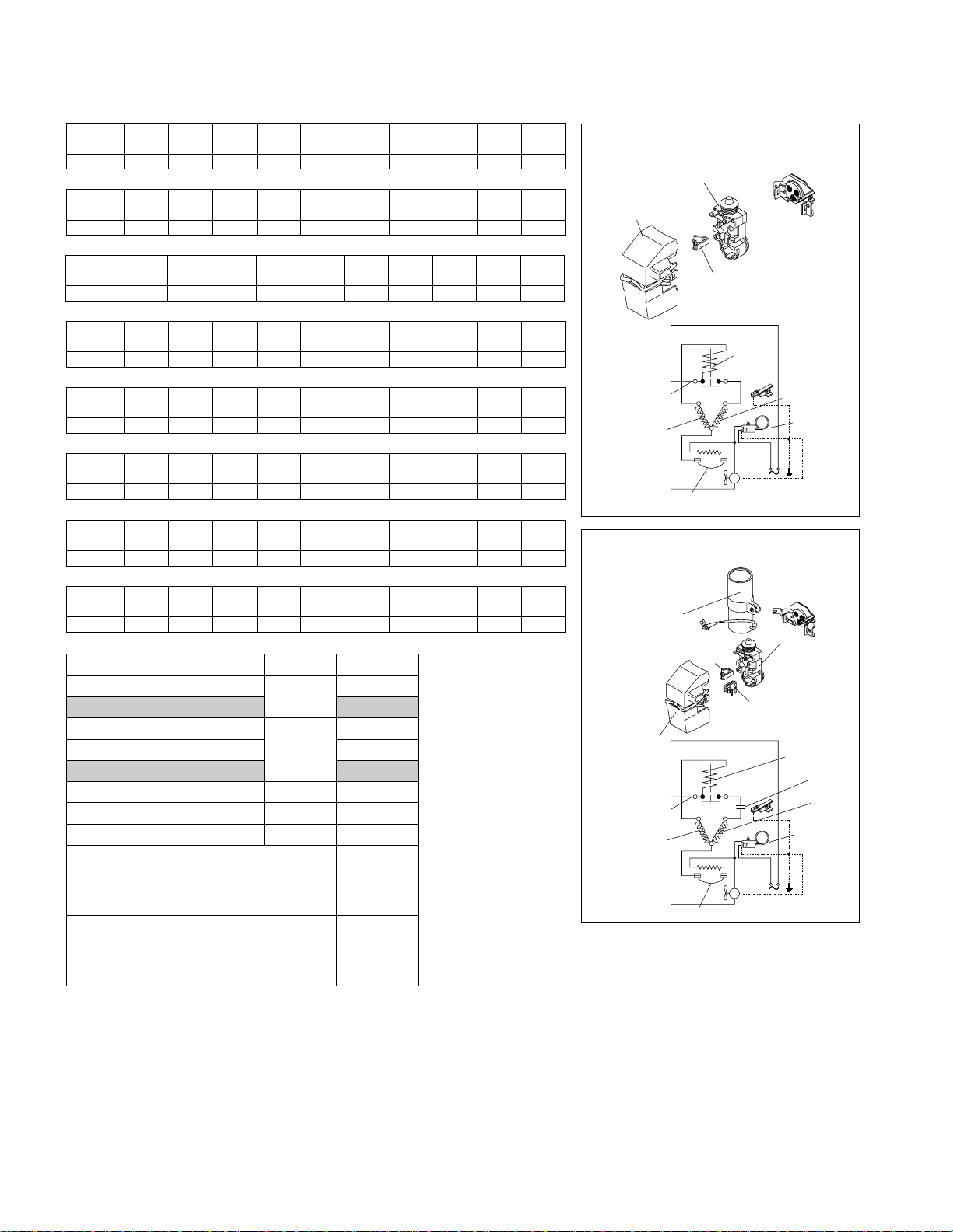
Main winding
Motor protector
Start winding
a2
b
a2
d
Thermostat
Capacity at LBP conditions (ASHRAE) Btu/h
8226
10
121113
14
M
a2
Main winding
Motor protector
Start winding
c
Thermostat
a2
d
d
c
b
c
Danfoss can accept no responsibility for possible errors in catalogues, brochures and other printed material.Danfoss reserves the right to alter its products without notice. This also applies to
products already on order provided that such alterations can be made without subsequential changes being necessary in specifications already agreed.
All trademarks in this material are property of the respective companies. Danfoss and the Danfoss logotype are trademarks of Danfoss A/S. All rights reserved.
F°\.pmoC
03-
02-
31-
01-
52-
3.32-
C°\.pmoC
0
4.43-
9.82-
01
02
03
8.71-
2.21-
7.6-
04
1.1-
4.4
KF5.9FN3350575394201663178718922909233631404
Capacity at MBP conditions (ASHRAE) Btu/h
F°\.pmoC
03-
02-
31-
01-
52-
3.32-
C°\.pmoC
0
4.43-
9.82-
01
02
03
8.71-
2.21-
7.6-
04
1.1-
4.4
KF5.9FN474766138019412178519302085202230853
Capacity (EN 12900/CECOMAF) watt
C°\.pmoC
4.43-
9.82-
F°\.pmoC
52-
03-
02-
31-
3.32-
8.71-
2.21-
7.6-
1.1-
01-
0
01
02
4.4
03
04
KF5.9FN621871222342423424445986958559
Power consumption watt
F°\.pmoC
03-
02-
31-
01-
52-
3.32-
C°\.pmoC
0
4.43-
9.82-
01
02
03
8.71-
2.21-
7.6-
04
1.1-
4.4
KF5.9FN291822352462103833973224074694
Current consumption A
F°\.pmoC
03-
02-
31-
01-
52-
3.32-
C°\.pmoC
0
4.43-
9.82-
01
02
03
8.71-
2.21-
7.6-
04
1.1-
4.4
KF5.9FN54.395.307.367.359.361.404.476.469.411.5
EER at LBP conditions (ASHRAE) Btu/Wh
F°\.pmoC
03-
02-
31-
01-
52-
3.32-
C°\.pmoC
0
4.43-
9.82-
01
02
03
8.71-
2.21-
7.6-
04
1.1-
4.4
KF5.9FN77.282.396.388.355.482.570.698.637.751.8
EER at MBP conditions (ASHRAE) Btu/Wh
F°\.pmoC
03-
02-
31-
01-
52-
3.32-
C°\.pmoC
0
4.43-
9.82-
01
02
03
8.71-
2.21-
7.6-
04
1.1-
4.4
KF5.9FN74.229.282.354.340.496.493.511.658.622.7
COP (EN 12900/CECOMAF) W/W
C°\.pmoC
4.43-
9.82-
F°\.pmoC
52-
03-
02-
31-
3.32-
8.71-
2.21-
7.6-
1.1-
01-
0
01
02
4.4
03
04
KF5.9FN66.087.088.029.080.152.134.136.128.129.1
Accessories
seciveD.giFKF5.9FN
).lcnirotcetorp(yalergnitratS
).lcnirotcetorp(yalergnitratS
014roticapacgnitratS µF*8205U711
revoCb1201U711
feilerdroCd7130U711
roticapacfeilerdroCcd9430U711
seirosseccagnitnuoM )9295G501(
rosserpmocenoroftniojtloB
seirosseccagnitnuoM )7395G501(
seititnauqnino-panS
rosserpmocenoroftniojtloB
rosserpmocenorofno-panS
rosserpmocenoroftniojtloB
seititnauqnitniojtloB
2a
stnemurtsnIsaxeT"4/3rotcetorP 6-ZFA62TRM
)1.sop(
2a
c
5
3
5
5
5
5
2.sop( )
)mm(.niØ
/8)61(
/4)91(
/8)61(
)mm(.niØ
/8)61(
/8)61(
/8)61(
stnemurtsnIsaxeT"4/3rotcetorP 6-ZFA62TRM
Test conditions
1. Condensing temperature
2. Ambient & suction gas temp.
1414U711
3. Liquid temperature
Fan cooling F2, 115V 60Hz
*2414U711
ASHRAE
1. LBP 130°F (54,4°C)
2. 90°F (32°C)
3. 90°F (32°C)
1. MBP 130°F (54,4 °C)
2. 95°F (35°C)
3. 115°F (46°C)
EN 12900/CECOMAF
1. 55°C (131°F)
2. 32°C (90°F)
6491-811
3. 55°C (131°F)
9491-811
7491-811
7191-811
8191-811
9191-811
*In capillary tube systems where non-equalized pressures may occur at
compressor start, or in areas with short power supply drop-outs, a starting
capacitor can be used for ensuring a successful start (CSIR).
54
2.7
54
2.7
2.7
54
54
2.7
54
2.7
54
2.7
(pos.1)
54
2.7
2.7
54
(pos.2)
2 CG.43.W3.22 July 2003
 Loading...