

Page 1
Technical Information
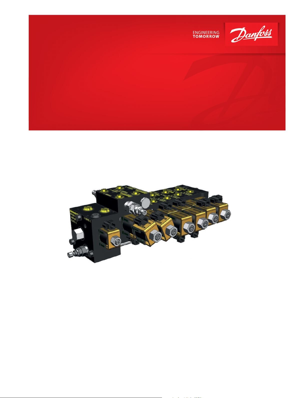
Module Valve Block
MVB10
www.danfoss.com
Page 2

Technical Information
MVB10 Module Valve Block
Revision history Table of revisions
Date Changed Rev
September 2020 Rebranded to Danfoss 0101
2 | © Danfoss | September 2020 BC353276907439en-000101
Page 3

Technical Information
MVB10 Module Valve Block
Contents
MVB10 Module HIC System
MVB10 technical data..................................................................................................................................................................... 4
System configuration guidelines................................................................................................................................................5
Inlet module
MVB10-I-LS..........................................................................................................................................................................................7
MVB10-I................................................................................................................................................................................................9
Inlet module component selection.........................................................................................................................................11
Interface module
MVB10-IF........................................................................................................................................................................................... 13
Working module
MVB10-W...........................................................................................................................................................................................15
MVB10-W-C...................................................................................................................................................................................... 17
MVB10-W-LH with counterbalance valves............................................................................................................................19
MVB10-W-LH with pilot check valves..................................................................................................................................... 21
MVB10-W-C-LH with counterbalance valves....................................................................................................................... 24
MVB10-W-C-LH with pilot check valves.................................................................................................................................27
MVB10-W-F.......................................................................................................................................................................................29
MVB10-W-F-LH with counterbalance valves........................................................................................................................31
MVB10-W-F-LH with pilot check valves................................................................................................................................. 34
Working module component selection.................................................................................................................................37
End module
MVB10-E............................................................................................................................................................................................ 40
Tie rod kits (seals included)
©
Danfoss | September 2020 BC353276907439en-000101 | 3
Page 4
Technical Information
MVB10 Module Valve Block
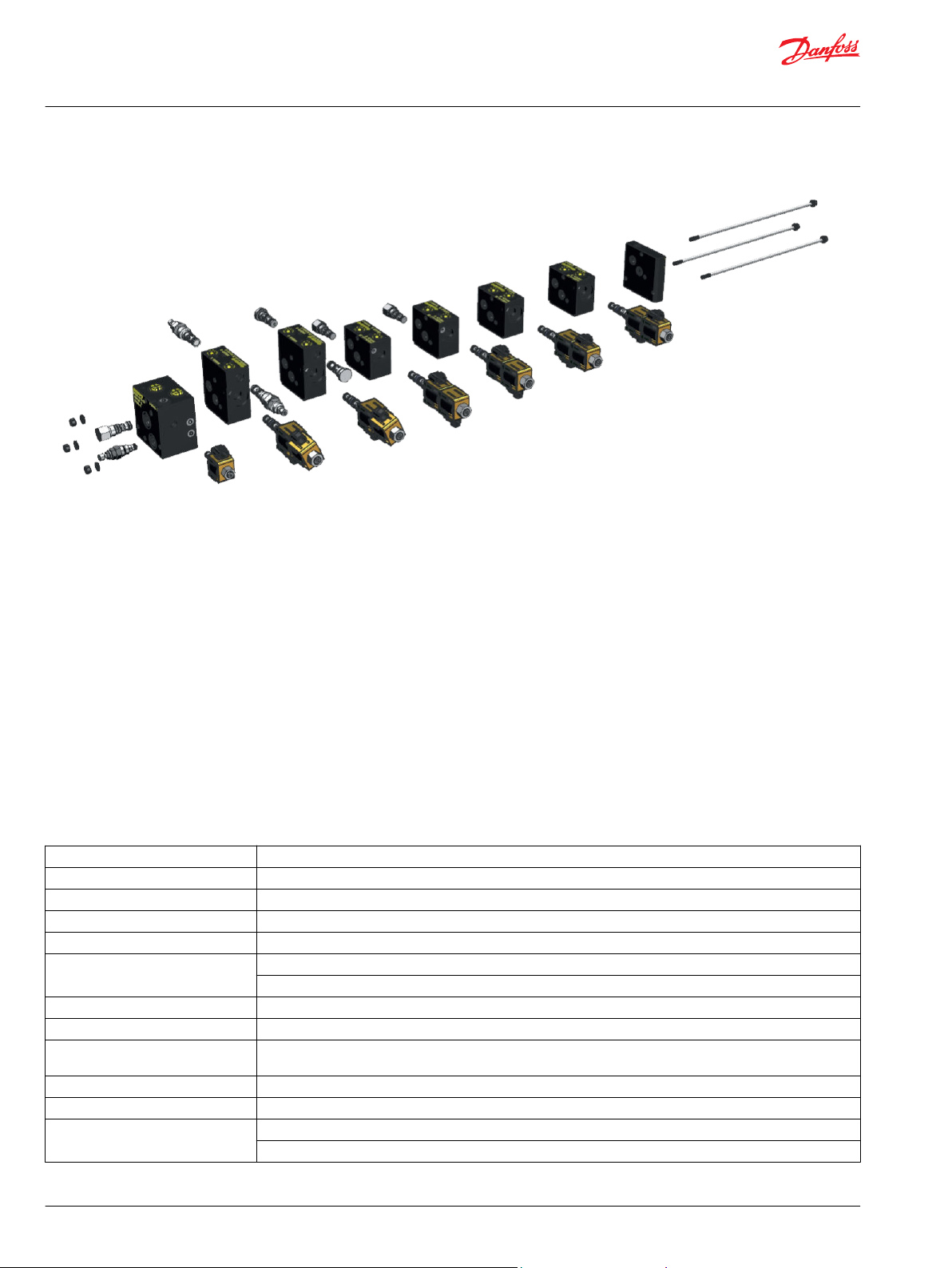
MVB10 Module HIC System
Danfoss has a range of modular HICs developed to match 40 years of experience in HIC and cartridge
design with today's market request of compact and flexible solutions. The Danfoss MVB10 system is
designed for the electro-hydraulic control of mobile machines for performance up to 80 l/min inlet flow
and 210 bar working pressure, rated to 1 million cycles according to the NFPA T2.6.1 endurance test.
The modularity concept enables machine developers to create flexible hydraulic control solutions with
standard components, ensuring the best speed to market is achieved with a high quality product.
Moreover, MVB10 is completely configurable, allowing end customers to apply standard, cost effective
solutions in applications.
The MVB10 also offers the flexibility to easily expand with optional features, thus reducing stock value
while increasing technical and logistic flexibility. MVB10 offers a unique synergy with Danfoss PVG 16 and
PVG 32 through an available interface module that allows the two products to be used in combination
while using common hardware. This capability unlocks a whole new and exciting potential for tailormade solutions that can match exactly the increasingly demanding the hydraulic controls market.
MVB10 technical data
General technical data
Ambient temperature -25° C to + 50° C
Input flow max 80 l/min [21.1 US gal/min]
Working section rated flow 22 l/min [5 US gal/min]
Load operating max pressure
Tank peak pressure
Oil temperature NBR seals: -40° C to 100° C [-40° F to 212° F]
Oil absolute viscosity limits 12-400 cSt [66-1854 SUS]
Oil recommended viscosity 12-54 cSt [66-250 SUS]
Permissible oil types See Danfoss documents Hydraulic Fluids and Lubricants (BC152886484524) and Biodegradable Hydraulic Fluids
Oil cleanliness ISO 4406: 18/17/13 or better
Maximum number of sections 10 (for more, consult your Danfoss representative)
Surface treatment Manifolds: black anodized
*
Rated pressure based on NFPA fatigue test standards (at 1 Million Cycles)
*
*
210 bar [3045 psi]
210 bar [3045 psi]
VITON seals: -26° C to 204° C [-15° F to 400° F]
Applications (520L0465)
Cartridges: zinc plated
4 | © Danfoss | September 2020 BC353276907439en-000101
Page 5
LE
MVB 10-I -LS
SV0
RV1
SH2
SH1
SV1
MVB 10- W
LE1
MVB 10-W- C
SH4
SH3
PSV 2
B1 A1 B2 A2
LS
P
T
SH6
SH5
CB1 CB2
PSV 3
MVB 10-W-C -LH- VCB0 6
LE2
MVB 10-E
Orifice
Provision
B3 A3
Tan k
Pum p
Technical Information
MVB10 Module Valve Block
MVB10 Module HIC System
System configuration guidelines
Every MVB assembly is composed of the following base parts:
•
An inlet section or a PVG 32/16 interface
•
One or more work sections
•
An end plate
Work sections are available with the following functions:
•
On-off
•
On-off with integrated load holding
•
Proportional compensated
•
Proportional compensated with integrated load holding
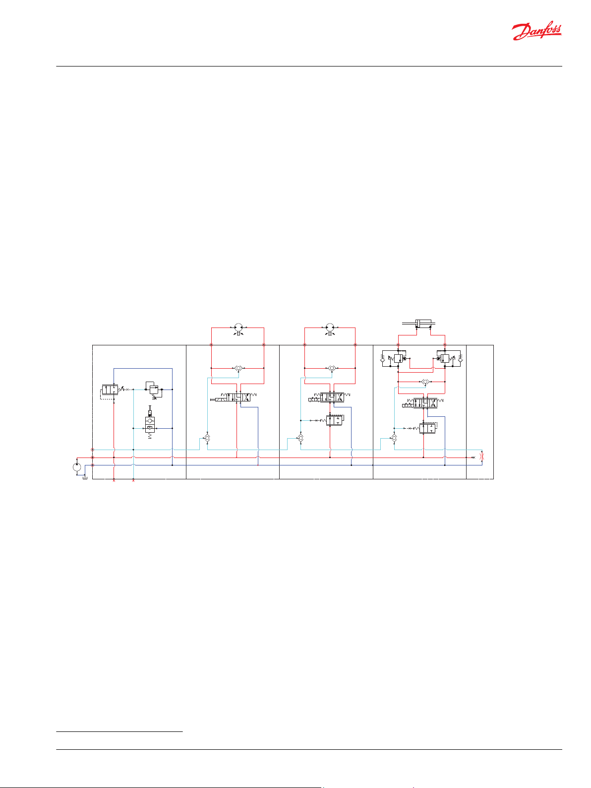
Configuration example 1
3-function assembly for fixed displacement pump with 1 on-off directional controlled section, 1 proportional section, 1 proportional
section with load holding function. System is provided with a shut-off valve, a relief valve and a logic element to bypass excessive flow.
Proportional sections are locally compensated.
*
©
Danfoss | September 2020 BC353276907439en-000101 | 5
*
Load holding module allows the use of either counterbalance or pilot operated check valves
Page 6
MVB10- I
SH2
SH1
SV1
MVB 10-W
LE1
MVB 10-W-C
SH4
SH3
PSV 2
B1 A1 B2 A2
MVB10- E
Orifice
Provision
B3 A3
Ls
P
T
Load Sen sing Pump
Tank
SH6
SH5
SV3
PC1 PC2
MVB 10-W-LH-R PC0 6
Technical Information
MVB10 Module Valve Block
MVB10 Module HIC System
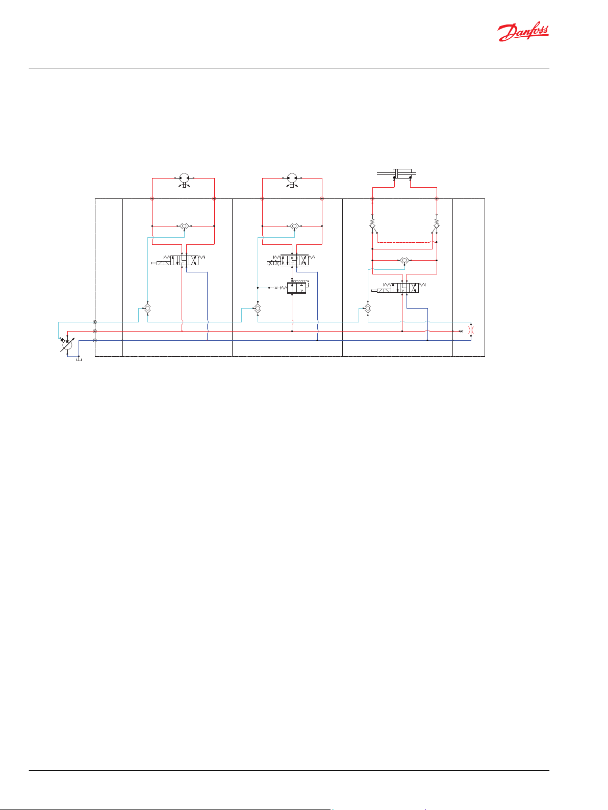
Configuration example 2
3-function assembly for LS pump with 1 on-off directional controlled section, 1 proportional section and 1 on-off section with load
holding. Proportional sections are locally compensated.
6 | © Danfoss | September 2020 BC353276907439en-000101
Page 7
LS
T
P
LS
T
P
MVB10
interface
RV
SV
LE
MP
MLS
Technical Information
MVB10 Module Valve Block
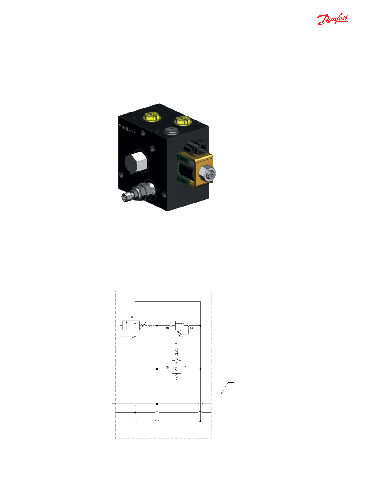
Inlet module
MVB10-I-LS
Operation
This inlet module is designed to operate in systems using either a fixed or variable displacement pump.
Threaded ports are provided for external connection to the P, T and LS lines.
For applications with a fixed pump, the enable valve (SV) will allow all flow to bypass to tank at low
pressure when de-energized. When energized, a logic element (LE) is used to efficiently bypass excess
flow not used by the work sections to tank. The included LS relief valve (RV) limits the overall system
pressure. This inlet section can also be configured to be applied with a variable displacement pump by
replacing the logic element(LE) with a closed cavity plug (CP10-B- 3S-B).
Inlet module with compensation, relief and enable valve
©
Danfoss | September 2020 BC353276907439en-000101 | 7
Page 8
LIFTING HOLE M10
Technical Information
MVB10 Module Valve Block
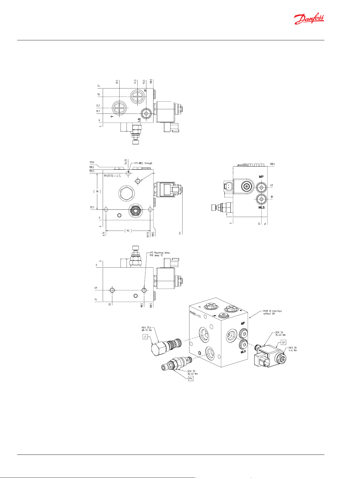
Inlet module
MVB10-I-LS dimension drawing
8 | © Danfoss | September 2020 BC353276907439en-000101
Page 9
LS
T
P
MVB10
interface
LS
T
P
Technical Information
MVB10 Module Valve Block
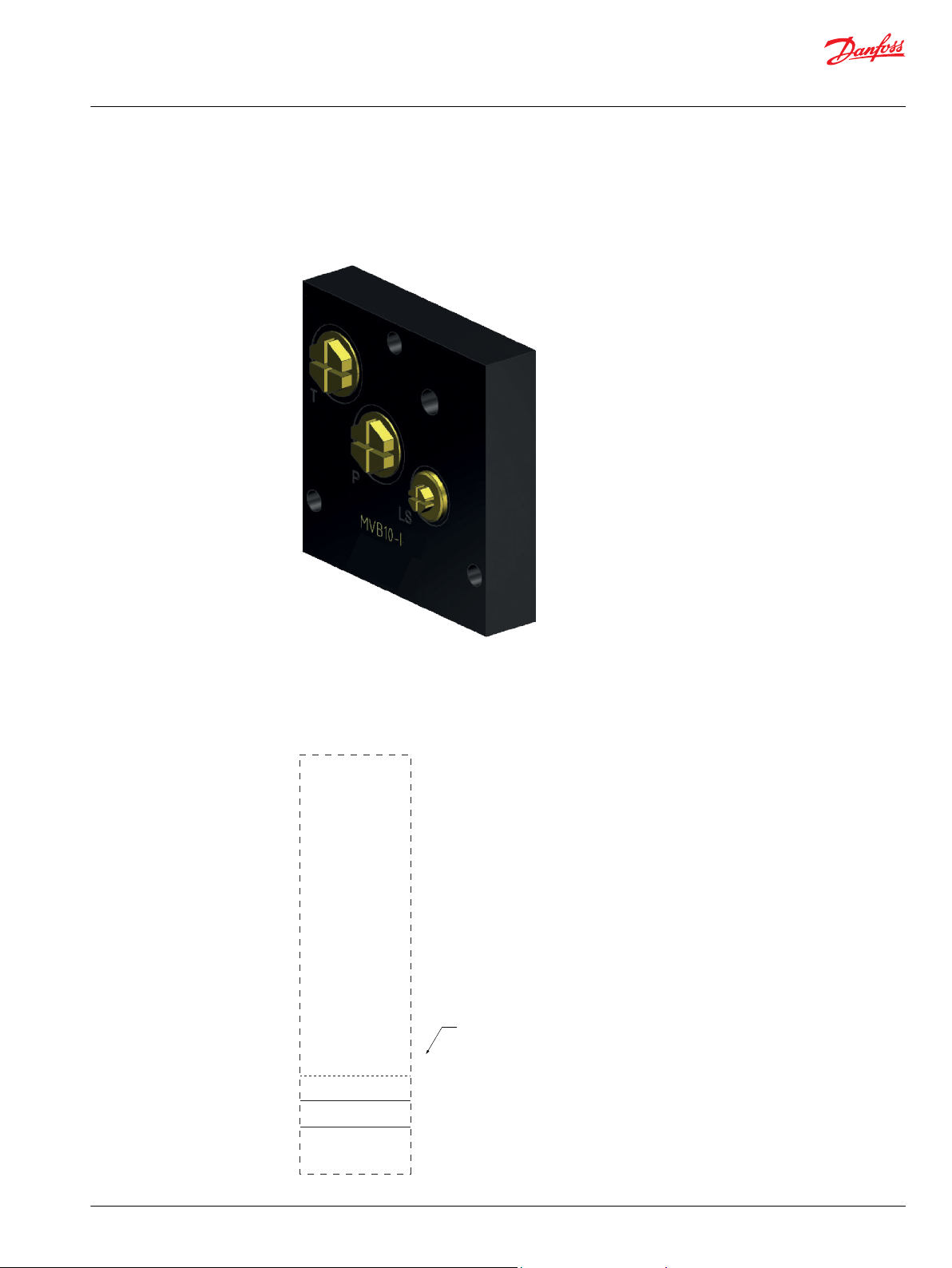
Inlet module
MVB10-I
Operation
This inlet module provides standard port connections to the P, T and LS lines in the MVB10 stack. It does
not include any active components.
Standard inlet module
©
Danfoss | September 2020 BC353276907439en-000101 | 9
Page 10
MVB10 interface
Technical Information
MVB10 Module Valve Block
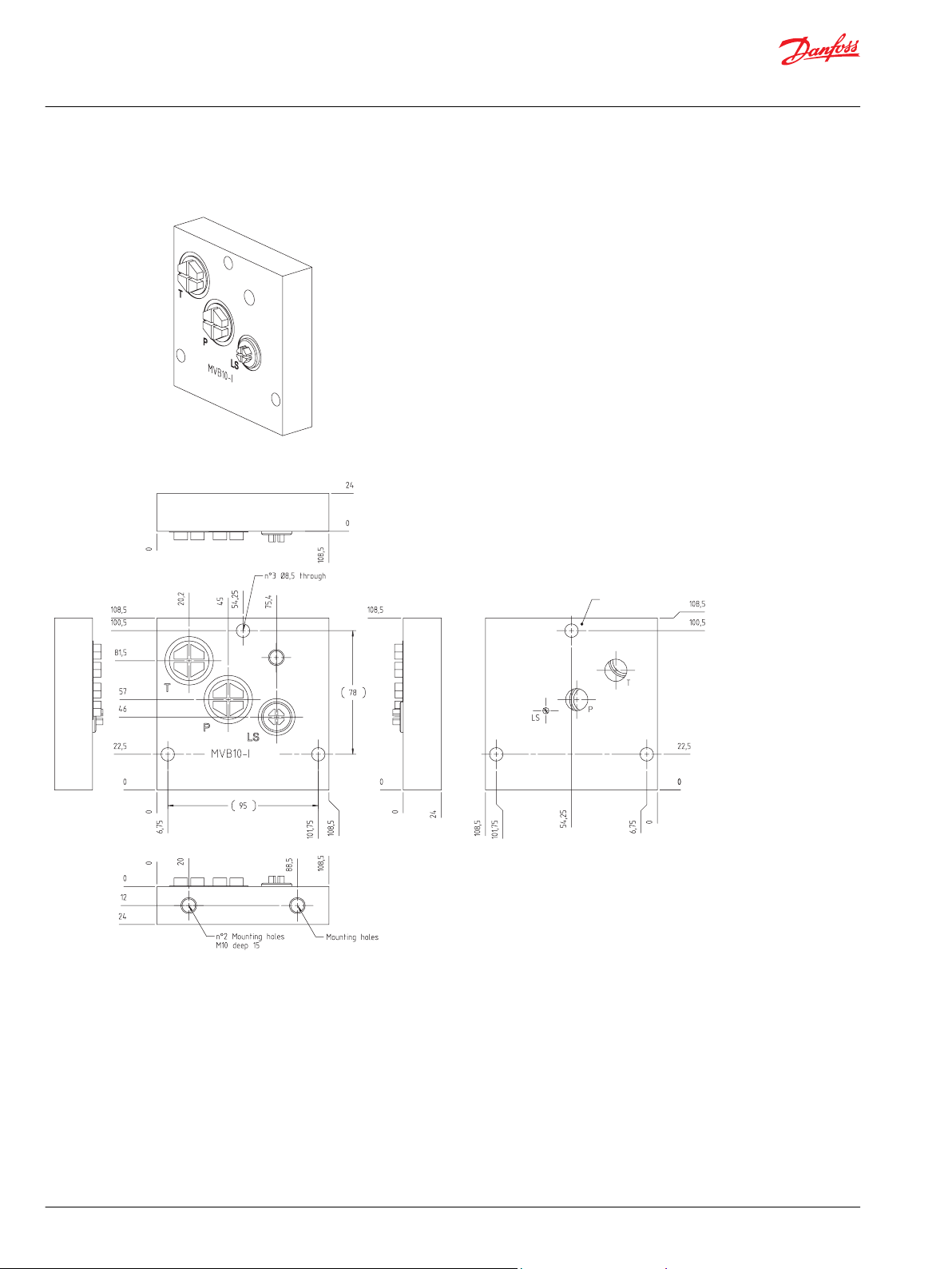
Inlet module
MVB10-I dimension drawing
10 | © Danfoss | September 2020 BC353276907439en-000101
Page 11
LS
T
P
LS
T
P
LS
T
P
LS
T
P
MVB10-I
MVB10-I-LS
MP
MLS
LS
RV
SV
Technical Information
MVB10 Module Valve Block
Inlet module
Inlet module component selection
The options for the inlet module area standard version equipped only with ports or an LS version
equipped with cartridge valves.
For the valve selection:
•
•
•
Inlet module component selection
The relief valve (RV) will limit system pressure through regulating the pressure in the LS passage. If
the LS pressure is controlled by an external component,this can be replaced with a plug
The logic element (LE) will bypass excess flow to tank when applied with a fixed pump. LE can be
replaced with a plug when applied with a variable displacement pump. In this case we recommend
an external relief valve to protect the circuit
The enable valve (SV) will allow flow to be bypassed at low pressure when de-energized through
connecting the LS signal to tank. It will also disable the system in the case of power loss
Cartridges shown in red are not included as a part of the base module and must be purchased separately.
Refer to Inlet module component selection on page 11 for available options.
Inlet module component selection
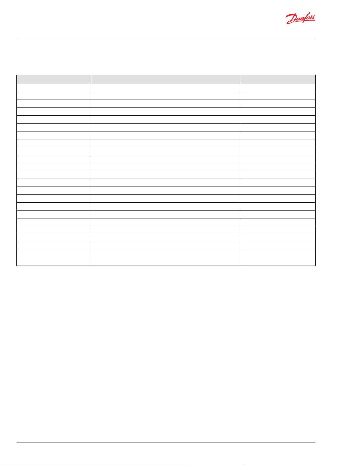
Model code Description Part number
Body Type
MVB10-I-4B Standard Inlet Section. P and T: 1/2 BSP. LS: 1/4 BSP 11193649
MVB10-I-10S Standard Inlet Section. P and T: #10 SAE. LS: #6 SAE 11198412
MVB10-I-LS-4B Inlet section with compensation: relief and shut off options. P and T:1/2
MVB10-I-LS-10S Inlet section with compensation: relief and shut off options. P and T: #10
SV - Solenoid Valve (for additional options, see M13 & R13 coil catalog pages)
CP08-B-2-B No solenoid valve - Plug - Buna seals 920554
SVP08-NO-00-00-B-00 Solenoid valve - push pin override - no screen - Buna seals 805315219
SV - Solenoid Valve Coil (for additional options, see SVP08-NO technical information)
M13-24D-20W-DN Standard Coil: DIN 43650 connector, 24V 171139819
©
Danfoss | September 2020 BC353276907439en-000101 | 11
BSP ports. LS, MLS, MP: 1/4 BSP
SAE. LS, MLS, MP: #6 SAE
11189404
11195194
Page 12
Technical Information
MVB10 Module Valve Block
Inlet module
Inlet module component selection (continued)
Model code Description Part number
M13-12D-20W-DN Standard Coil: DIN 43650 connector, 12V 171140019
M13-24D-20W-DE Standard Coil: Deutsch DT04-2P connector, 24V 17114131
M13-12D-20W-DE Standard Coil: Deutsch DT04-2P connector, 12V 17114141
R13-24D-16W-DE Robust Coil: Deutsch DT04-2P connector, 24V 171180419
R13-12D-16W-DE Robust Coil: Deutsch DT04-2P connector, 12V 171180619
RV - Relief Valve (for additional options, see RV08-DR catalog page)
CP08-B-2-B No Relief valve - Plug - Buna seals 920554
RV08-DR-2-E-100-B-00 Relief valve: external screw adjustment, Buna seals, 100 bar setting 810216519
RV08-DR-2-E-110-B-00 Relief valve: external screw adjustment, Buna seals, 110 bar setting 83054656
RV08-DR-2-E-120-B-00 Relief valve: external screw adjustment, Buna seals, 120 bar setting 83014557
RV08-DR-3-E-130-B-00 Relief valve: external screw adjustment, Buna seals, 130 bar setting 83051234
RV08-DR-3-E-140-B-00 Relief valve: external screw adjustment, Buna seals, 140 bar setting 83016195
RV08-DR-3-E-150-B-00 Relief valve: external screw adjustment, Buna seals, 150 bar setting 83006885
RV08-DR-3-E-160-B-00 Relief valve: external screw adjustment, Buna seals, 160 bar setting 83022156
RV08-DR-3-E-170-B-00 Relief valve: external screw adjustment, Buna seals, 170 bar setting 83024408
RV08-DR-3-E-180-B-00 Relief valve: external screw adjustment, Buna seals, 180 bar setting 83024684
RV08-DR-3-E-190-B-00 Relief valve: external screw adjustment, Buna seals, 190 bar setting 83006694
RV08-DR-3-E-200-B-00 Relief valve: external screw adjustment, Buna seals, 200 bar setting 810217319
RV08-DR-3-E-210-B-00 Relief valve: external screw adjustment, Buna seals, 210 bar setting 83018587
LS - Compensator (for additional options, see HLE10-CPC and HLEA10-CPC catalog pages)
CP10-B-3S-B No compensator - plug - Buna seals 11018366
HLE10-CPC-15-B-00 Compensator - 15 bar bias spring - Buna seals 83038529
HLEA10-CPC-E-15-B-00 Adjustable compensator - 15 bar setting - Buna seals 83033826
12 | © Danfoss | September 2020 BC353276907439en-000101
Page 13
MVB10
interface
PVG 32
interface
LS
T
P
LS
T
P
PP
T0
Technical Information
MVB10 Module Valve Block
Interface module
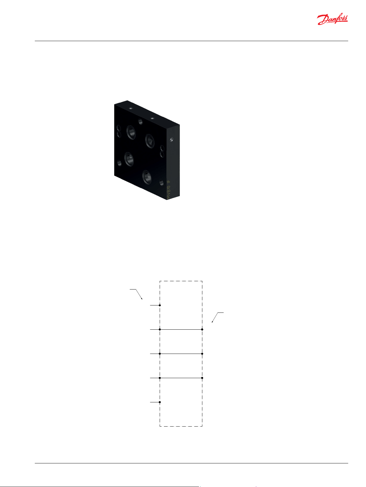
MVB10-IF
Operation
This connection interface does not include any active components and may be used to connect MVB10
modules with PVG32/16 modules. The unique synergy between the MVB10 and the Danfoss PVG product
line allows the use of the same tie-rods kits across both product groups. This enables assemblies the
flexibility to be expanded across both product lines to meet the configuration requirements.
Before combining MVB10 sections with products from the Danfoss PVG product families, carefully read
and consider the relevant operating instructions provided by Danfoss. Failure to comply with these
instructions may result in performance or safety issues.
Standard inlet module
©
Danfoss | September 2020 BC353276907439en-000101 | 13
Page 14

Technical Information
MVB10 Module Valve Block
Interface module
MVB10-IF dimension drawing
Application awareness
Standard open center PVG inlets use a 10 bar (145 psi) compensating element. When using a
compensated MVB10 work section with this inlet, a compensator of 7 bar (100 psi) or less is
recommended.
The PVG and the MVB10 will share a common inlet when used with the standard interface plate (MVB10IF). The maximum pressure rating of the entire stack will be 210 bar (3000 psi).
When a non-compensated work section is applied with a high inlet pressure and low load pressure, the
high pressure differential can cause the flow rate to exceed catalog rating of the solenoid. The operating
envelope of the solenoid valve should be followed to ensure proper shifting. Careful evaluation should
be given to applications using pressure compensated pumps as well as those requiring simultaneous use
of multiple functions with differing loads. In these types of applications where there is a risk of
overflowing the solenoid, a compensated or flow control work section can be used.
Interface module component selection
Model code Description Part number
MVB10-IF PVG Interface Plate 11187916
14 | © Danfoss | September 2020 BC353276907439en-000101
Page 15

LS
T
P
MVB10
interface
LS
T
P
MVB10
interface
SH1
SH2
SV
B
A
MVB10-W
Technical Information
MVB10 Module Valve Block
Working module
MVB10-W
Operation
This work section provides on-off directional control of a double acting actuator.
This is a non-compensated module. High pressure differentials across this section can cause the flow rate
to exceed catalog rating of the solenoid. The operating envelope of the solenoid valve should be
followed to ensure proper shifting. For valve operating limits,review the solenoid valve catalog page. For
additional information, see the application note in the Component Selection section of this catalog.
Non-compensated working module
©
Danfoss | September 2020 BC353276907439en-000101 | 15
Page 16

Technical Information
MVB10 Module Valve Block
Working module
MVB10-W dimension drawing
16 | © Danfoss | September 2020 BC353276907439en-000101
Page 17

LS
T
P
MVB10
interface
LS
T
P
MVB10
interface
MVB10-W-C
B A
SH1
SH2
PSV
LE1
Technical Information
MVB10 Module Valve Block
Working module
MVB10-W-C
Operation
This pressure compensated work section provides proportional load-independent directional control of a
double acting actuator.
Compensated working module
©
Danfoss | September 2020 BC353276907439en-000101 | 17
Page 18

Technical Information
MVB10 Module Valve Block
Working module
MVB10-W-C dimension drawing
18 | © Danfoss | September 2020 BC353276907439en-000101
Page 19

LS
T
P
MVB10
interface
LS
T
P
MVB10
interface
MVB10-W-LH-VCB06
B A
SH1
SH2
SV
CB2
CB1
Technical Information
MVB10 Module Valve Block
Working module
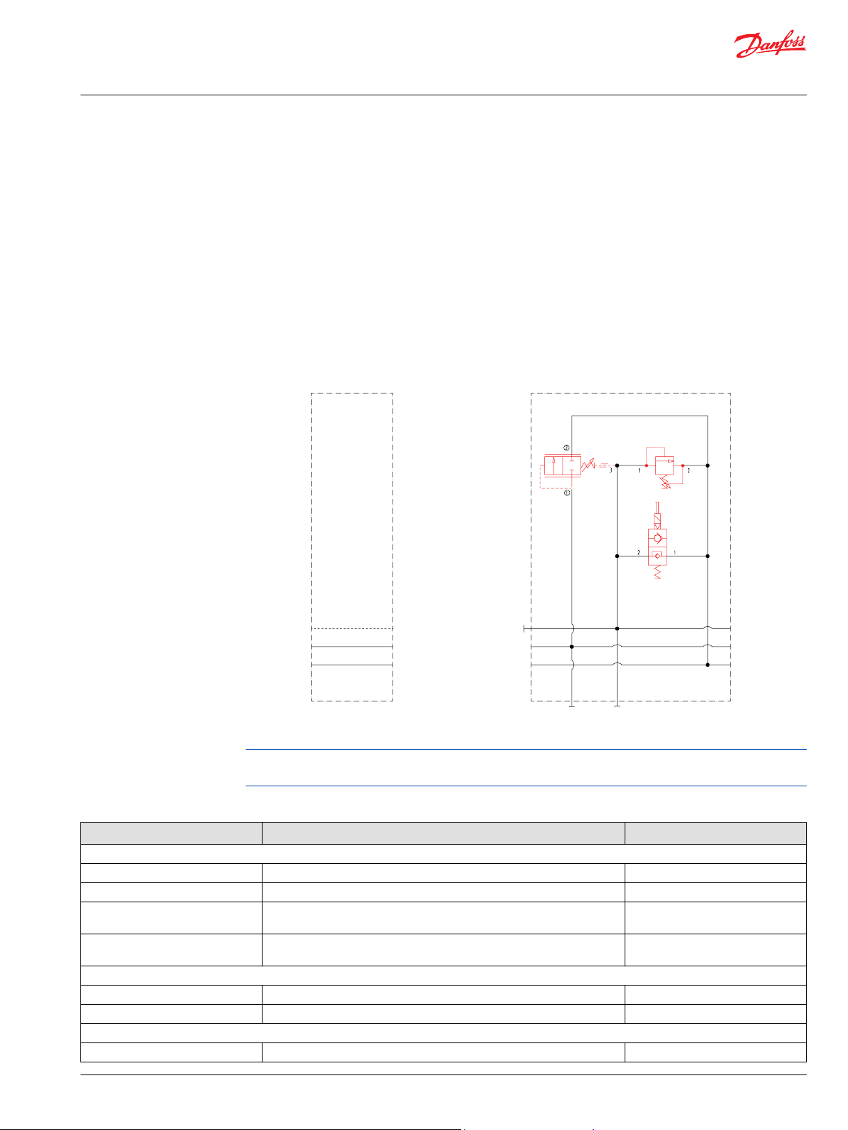
MVB10-W-LH with counterbalance valves
Operation
This work section provides on-off directional control of a double acting actuator. A load holding cartridge
keeps an actuator in position by preventing any leakage that may cause drifting.
Counter balance valves help control the movement of lowering or runaway loads by restricting the flow
returning to tank from the actuator. They also provide an antishock function by limiting the maximum
pressure inside the actuator.
To ensure proper operation, this load holding module should always be specified with a directional
control valve which connects the work ports to tank in the neutral position.
This is a non-compensated module. High pressure differentials across this section can cause the flow rate
to exceed catalog rating of the solenoid. The operating envelope of the solenoid valve should be
followed to ensure proper shifting. For valve operating limits, review the solenoid valve catalog page. For
additional information, see the application note in the Component Selection section of this catalog.
Load holding with counterbalance
©
Danfoss | September 2020 BC353276907439en-000101 | 19
Page 20
Technical Information
MVB10 Module Valve Block
Working module
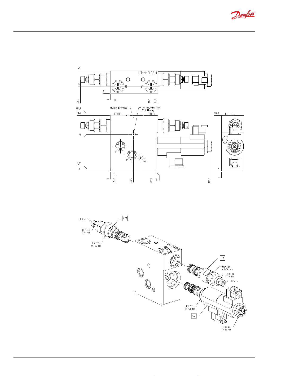
MVB10-W-LH with counterbalance valves dimension drawing
20 | © Danfoss | September 2020 BC353276907439en-000101
Page 21

Technical Information
MVB10 Module Valve Block
Working module
MVB10-W-LH with pilot check valves
Operation
This work section provides on-off directional control of a double acting actuator. A load holding cartridge
keeps an actuator in position by preventing any leakage that may cause drifting.
Pilot operated check valves minimize the restriction of flow to and from the actuator and therefore help
achieve the best energy efficiency in simple load control situations.
To ensure proper operation, this load holding module should always be specified with a directional
control valve which connects the work ports to tank in the neutral position.
This is a non-compensated module. High pressure differentials across this section can cause the flow rate
to exceed catalog rating of the solenoid. The operating envelope of the solenoid valve should be
followed to ensure proper shifting. For valve operating limits, review the solenoid valve catalog page. For
additional information, see the application note in the Component Selection section of this catalog.
©
Danfoss | September 2020 BC353276907439en-000101 | 21
Page 22
LS
T
P
MVB10
interface
LS
T
P
MVB10
interface
MVB10-W-LH-RPC06
B A
SH1
SH2
SV
PC2
PC1
Technical Information
MVB10 Module Valve Block
Working module
Load holding with pilot check valves
22 | © Danfoss | September 2020 BC353276907439en-000101
Page 23

Technical Information
MVB10 Module Valve Block
Working module
MVB10-W-LH with pilot check valves dimension drawing
©
Danfoss | September 2020 BC353276907439en-000101 | 23
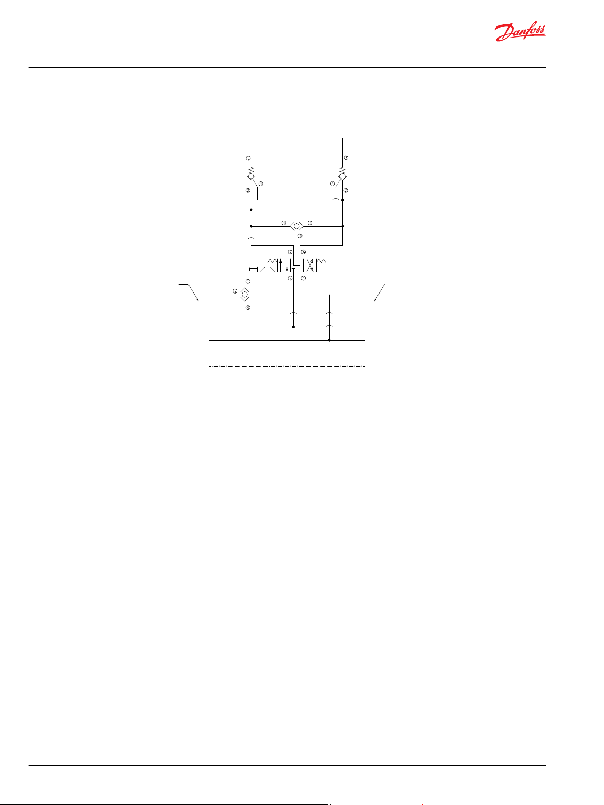
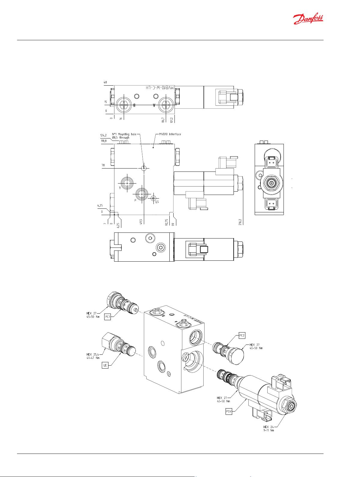
Page 24

Technical Information
MVB10 Module Valve Block
Working module
MVB10-W-C-LH with counterbalance valves
Operation
This pressure compensated work section provides proportional load-independent directional control of a
double acting actuator. A load holding device keeps an actuator in position by preventing any leakage
that may cause drifting.
Counterbalance valves help control the movement of lowering or run-away loads by restricting the flow
returning to tank from the actuator. They also provide an antishock function by limiting the maximum
pressure inside the actuator.
To ensure proper operation, this load holding module should always be specified with a directional
control valve which connects the work ports to tank in the neutral position.
24 | © Danfoss | September 2020 BC353276907439en-000101
Page 25

LS
T
P
MVB10
interface
LS
T
P
MVB10
interface
MVB10-W-C-LH-VCB06
B A
SH1
SH2
PSV
CB2
CB1
LE1
Technical Information
MVB10 Module Valve Block
Working module
Compensated working module load holding with pilot check valve
©
Danfoss | September 2020 BC353276907439en-000101 | 25
Page 26

Technical Information
MVB10 Module Valve Block
Working module
MVB10-W-C-LH with counterbalance valve dimension drawing
26 | © Danfoss | September 2020 BC353276907439en-000101
Page 27

LS
T
P
MVB10
interface
LS
T
P
MVB10
interface
MVB10-W-C-LH-RPC06
B A
SH1
SH2
PSV
PC2
PC1
LE1
Technical Information
MVB10 Module Valve Block
Working module
MVB10-W-C-LH with pilot check valves
Operation
This pressure compensated work section provides proportional load-independent directional control of a
double acting actuator. A load holding device keeps an actuator in position by preventing any leakage
that may cause drifting.
Pilot operated check valves minimize the restriction of flow to and from the actuator and therefore help
achieve the best energy efficiency in simple load control situations.
To ensure proper operation, this load holding module should always be specified with a directional
control valve which connects the work ports to tank in the neutral position.
Compensated working module
©
Danfoss | September 2020 BC353276907439en-000101 | 27
Page 28
Technical Information
MVB10 Module Valve Block
Working module
MVB10-W-C-LH with pilot check valves dimension drawing
28 | © Danfoss | September 2020 BC353276907439en-000101
Page 29

P
T
LS
3
2
1
2
4
3 1
SV1
3
2
1
B A
P
T
LS
MVB10-W-F
2
1
FC1
MVB10
interface
MVB10
interface
Technical Information
MVB10 Module Valve Block
Working module
MVB10-W-F
Operation
This work section provides on-off directional control of a double acting actuator. The flow control before
the directional valve will limit the flow through the section to the actuator. An SDC10-2 cavity is provided
for the flow control valve, allowing the use of a pressure compensated flow control or non-compensated,
adjustable needle valve.
High pressure differentials across this section can cause the flow rate to exceed catalog rating of the
solenoid when used with non-compensated flow controls. The operating envelope of the solenoid valve
should be followed to ensure proper shifting. For valve operating limits, review the solenoid valve
catalog page. For additional information, see the application note in Working module component selection
on page 37.
Flow control working module
©
Danfoss | September 2020 BC353276907439en-000101 | 29
Page 30

Technical Information
MVB10 Module Valve Block
Working module
MVB10-W-F dimension drawing
30 | © Danfoss | September 2020 BC353276907439en-000101
Page 31

Technical Information
MVB10 Module Valve Block
Working module
MVB10-W-F-LH with counterbalance valves
Operation
This work section provides on-off directional control of a double acting actuator. The flow control before
the directional valve will limit the flow through the section to the actuator. An SDC10-2 cavity is provided
for the flow control valve, allowing the use of a pressure compensated flow control or non-compensated,
adjustable needle valve. A load holding cartridge keeps an actuator in position by preventing any
leakage that may cause drifting.
Counter balance valves help control the movement of lowering or runaway loads by restricting the flow
returning to tank from the actuator. They also provide an antishock function by limiting the maximum
pressure inside the actuator.
To ensure proper operation, this load holding module should always be specified with a directional
control valve which connects the work ports to tank in the neutral position.
High pressure differentials across this section can cause the flow rate to exceed catalog rating of the
solenoid when used with non-compensated flow controls. The operating envelope of the solenoid valve
should be followed to ensure proper shifting. For valve operating limits, review the solenoid valve
catalog page. For additional information, see the application note in Working module component selection
on page 37.
©
Danfoss | September 2020 BC353276907439en-000101 | 31
Page 32

P
T
LS
3
2
1
2
4
3 1
SV
3
2
1
B A
1
2
3
CB2
P
T
LS
1
2
3
CB1
MVB10-W-F-LH-VCB06
2
1
FC
MVB10
interface
MVB10
interface
Technical Information
MVB10 Module Valve Block
Working module
Flow control and load holding with counterbalance
32 | © Danfoss | September 2020 BC353276907439en-000101
Page 33

Technical Information
MVB10 Module Valve Block
Working module
MVB10-W-F-LH with counterbalance valve dimension drawing
©
Danfoss | September 2020 BC353276907439en-000101 | 33
Page 34

Technical Information
MVB10 Module Valve Block
Working module
MVB10-W-F-LH with pilot check valves
Operation
This work section provides on-off directional control of a double acting actuator. The flow control before
the directional valve will limit the flow through the section to the actuator. An SDC10-2 cavity is provided
for the flow control valve, allowing the use of a pressure compensated flow control or non-compensated,
adjustable needle valve. A load holding cartridge keeps an actuator in position by preventing any
leakage that may cause drifting.
Pilot operated check valves minimize the restriction of flow to and from the actuator and therefore help
achieve the best energy efficiency in simple load control situations.
To ensure proper operation, this load holding module should always be specified with a directional
control valve which connects the work ports to tank in the neutral position.
High pressure differentials across this section can cause the flow rate to exceed catalog rating of the
solenoid when used with non-compensated flow controls. The operating envelope of the solenoid valve
should be followed to ensure proper shifting. For valve operating limits, review the solenoid valve
catalog page. For additional information, see the application note in Working module component selection
on page 37.
34 | © Danfoss | September 2020 BC353276907439en-000101
Page 35

P
T
LS
3
2
1
2
4
3 1
SV1
3
2
1
B A
P
T
LS
MVB10-W-F-LH-RPC06
2
1
FC1
2
1
3
PC1
2
1
3
PC2
MVB10
interface
MVB10
interface
Technical Information
MVB10 Module Valve Block
Working module
Flow control and load handling with pilot check valves
©
Danfoss | September 2020 BC353276907439en-000101 | 35
Page 36

Technical Information
MVB10 Module Valve Block
Working module
MVB10-W-F-LH with pilot check valves dimension drawing
36 | © Danfoss | September 2020 BC353276907439en-000101
Page 37

Technical Information
MVB10 Module Valve Block
Working module
Working module component selection
The working modules can have on/off or proportional compensated directional control, with or without
load holding.
The design of a new valve stack begins with the selection of the empty module, according to the required
function.
The load sense shuttle valves are included in all base modules and do not need to be specified separately.
It is possible to select the required components that can be specified in the module.
All of the solenoid and proportionals valves in the table can fit in all modules.
All of the logic elements in the table are compatible with all pressure compensated modules (-C).
All of the load holding valves in the table, both pilot operated check or counterbalance valves, are
compatible with all load holding modules(-LH).
When a non-compensated work section is applied with a high inlet pressure and low load pressure, the
high pressure differential can cause the flow rate to exceed catalog rating of the solenoid.
The operating envelope of the solenoid valve should be followed to ensure proper shifting. Careful
evaluation should be given to applications using pressure compensated pumps and those requiring
simultaneous use of multiple functions with differing loads. In these types of applications where there is a
risk of overflowing the solenoid, a compensated or flow control work section can be used.
©
Danfoss | September 2020 BC353276907439en-000101 | 37
Page 38

B A
B A
B A
B A
B A
MVB10-W-C-LH-RPC06
MVB10-W-C-LH-VCB06
MVB10-W-C
MVB10-W
MVB10-W-LH-RPC06
LS
T
P
LS
T
P
LS
T
P
LS
T
P
LS
T
P
LS
T
P
T
P
LS
T
P
LS
T
P
LS
T
P
SV
PSV
SV
PSV PSV
LE
PC1
PC2
LE LE
PC1 PC2
CB1
CB2
3
2
1
2 4
3
1
3
2
1
1
2
3
1
2
3
2
1
MVB10-W-F-LH-VCB06
LS
T
P
LS
T
P
B
A
FC
SV
CB1
CB2
Technical Information
MVB10 Module Valve Block
Working module
Working module component selection
Cartridges shown in red are not included as a part of the base module and must be purchased separately.
Refer to Working module component selection on page 39 for available options.
38 | © Danfoss | September 2020 BC353276907439en-000101
Page 39

Technical Information
MVB10 Module Valve Block
Working module
Working module component selection
Model code Description Part number
Body Type
MVB10-W-3B Working module, non compensated, A and B ports G3/8 BSP 11187533
MVB10-W-6S Working module, non compensated, A and B ports SAE#6 11195179
MVB10-W-C-3B Working module, compensated, A and B ports G3/8 BSP 11187535
MVB10-W-C-6S Working module, compensated, A and B ports SAE#6 11195178
MVB10-W-LH-3B Working module, non compensated, with load holding, A and B ports G3/8 BSP 11188879
MVB10-W-LH-6S Working module, non compensated, with load holding, A and B ports SAE#6 11195193
MVB10-W-C-LH-3B Working module, compensated, with load holding, A and B ports G3/8 BSP 11196245
MVB10-W-C-LH-6S Working module, compensated, with load holding, A and B ports SAE#6 11198419
MVB10-W-F-3B Working module, flow control, A and B ports G3/8 BSP 11229694
MVB10-W-F-6S Working module, flow control, A and B ports SAE#6 11202459
MVB10-W-F-LH-3B
MVB10-W-F-LH-6S
SV/PSV - Solenoid Valve - (for additional options, see SV10-34-05 and PSV10-34-05 catalog pages)
SV10-34-05-00-00-B-00 ON-OFF solenoid valve, 4 ways 3 positions, Buna seals 805314819
PSV10-34-05-00-00-22-B-00 Proportional solenoid valve, 4 ways 3 positions, Buna seals 850168919
SV10-34-05-00-00-PAP-00 ON-OFF solenoid valve, 4 ways 3 positions, Buna seals, Push/Pull Override 11181460
PSV10-34-05-00-00-22-B-PAP-00 Proportional solenoid valve, 4 ways 3 positions, Buna seals, Push/Pull Override 11227515
SV/PSV - Solenoid Valve Coil - (for additional options, see M16 and R16 catalog pages)
M16-12D-26W-DN Standard coil DIN 43650 connector, 12V 17114581
M16-24D-26W-DN Standard coil DIN 43650 connector, 24V 171146019
M16-12D-26W-DE Standard coil Deutsch DT04-2P connector, 12V 17114931
M16-24D-26W-DE Standard coil Deutsch DT04-2P connector, 24V 171149519
R16-12D-20W-DE Robust coil Deutsch DT04-2P connector, 12V 171185919
R16-24D-20W-DE Robust coil Deutsch DT04-2P connector, 24V 171183019
LE - Compensator - (for additional options, see CP700-4 catalog page)
CP700-4-B-0-150 Compensator - 10,3 bar bias spring - Buna Seals 133899
CP700-4-B-0-100 Compensator - 7,6 bar bias spring - Buna Seals 134241
CP10-B-3-B1 No compensator - Open plug 134493
PC/CB - Load Holding valve - (for additional options, see RPC06 and VCB06-EN catalog pages)
RPC06/0.5-00 Pilot Check valve - 0,5 bar - Buna Seals 11169090
RPC06/0.5-OR Pilot Check valve - 0,5 bar - Buna Seals - w/ piston Seal 11169102
RPC06/5-00 Pilot Check valve - 5 bar - Buna Seals 11169108
RPC06/5-OR Pilot Check valve - 5 bar - Buna Seals - w piston Seal 11169110
VCB06-EN-1-A-00-B 820202619
VCB06-EN-2-A-00-B Counterbalance valve - range 2 (70-210 bar) - Ratio A (7.1:1) - Buna
VCB06-EN-3-A-00-B Counterbalance valve - range 3 (105-350 Bar) - Ratio A (7.1:1) - Buna Seals 820202819
VCB06-EN-1-B-00-B Counterbalance valve - range 1 (25-140 bar) - Ratio B (4.1:1) - Buna Seals 820153929
VCB06-EN-2-B-00-B Counterbalance valve - range 2 (70-210 bar) - Ratio B (4.1:1) - Buna Seals 820158929
VCB06-EN-3-B-00-B Counterbalance valve - range 3 (105-350 Bar) - Ratio B (4.1:1) - Buna Seals 820159029
NCS06/0 Cavity Plug NCS06/0 920000619
FC - Flow Control - (for additional options, see CP300-1 and CP610-2 catalog pages)
CP300-1-B-0-2.4 Flow Control Valve - pressure compensated, 9 lpm - Buna Seals 83055469
CP610-2-B-0-K Needle Valve - adjustable, knob - Buna Seals 130453
Working module, flow control, with load holding, A and B ports G3/8 BSP
Working module, flow control, with load holding, A and B ports SAE#6
SealsCounterbalance valve - range 1 (25-140 bar) - Ratio A (7.1:1) - Buna Seals
11229782
11202460
820202719
©
Danfoss | September 2020 BC353276907439en-000101 | 39
Page 40

P
T
LS
MVB10-E
1
2
M8 Orifice
Provision
MVB10
interface
Technical Information
MVB10 Module Valve Block
End module
MVB10-E
Operation
This end plate section does not include any active components and may be used for closing a MVB10
assembly.
End plate section
40 | © Danfoss | September 2020 BC353276907439en-000101
Page 41

Technical Information
MVB10 Module Valve Block
End module
MVB10-E end module dimension drawing
End module component selection
Model code Description Part number
MVB10-E End plate 11187937
©
Danfoss | September 2020 BC353276907439en-000101 | 41
Page 42

Technical Information
MVB10 Module Valve Block
Tie rod kits (seals included)
Material number Order code / Nomenclature
157B8000 PVAS32-MOUNTING KIT-PVG L 054-072MM
157B8031 PVAS32-MOUNTING KIT-PVG L 078-096MM
157B8001 PVAS32-MOUNTING KIT-PVG L 102-120MM
157B8021 PVAS32-MOUNTING KIT-PVG L 126-144MM
157B8002 PVAS32-MOUNTING KIT-PVG L 150-168MM
157B8022 PVAS32-MOUNTING KIT-PVG L 174-192MM
157B8003 PVAS32-MOUNTING KIT-PVG L 198-216MM
157B8023 PVAS32-MOUNTING KIT-PVG L 222-240MM
157B8004 PVAS32-MOUNTING KIT-PVG L 246-264MM
157B8024 PVAS32-MOUNTING KIT-PVG L 270-288MM
157B8005 PVAS32-MOUNTING KIT-PVG L 294-312MM
157B8025 PVAS32-MOUNTING KIT-PVG L 318-336MM
157B8006 PVAS32-MOUNTING KIT-PVG L 342-360MM
157B8026 PVAS32-MOUNTING KIT-PVG L 366-384MM
157B8007 PVAS32-MOUNTING KIT-PVG L 390-408MM
157B8027 PVAS32-MOUNTING KIT-PVG L 414-432MM
157B8008 PVAS32-MOUNTING KIT-PVG L 438-456MM
157B8028 PVAS32-MOUNTING KIT-PVG L 462-480MM
157B8009 PVAS32-MOUNTING KIT-PVG L 486-504MM
157B8029 PVAS32-MOUNTING KIT-PVG L 510-528MM
157B8010 PVAS32-MOUNTING KIT-PVG L 534-552MM
157B8030 PVAS32-MOUNTING KIT-PVG L 558-576MM
157B8061 PVAS32-MOUNTING KIT-PVG L 582-600MM
157B8081 PVAS32-MOUNTING KIT-PVG L 606-624MM
157B8062 PVAS32-MOUNTING KIT-PVG L 630-648MM
157B8082 PVAS32-MOUNTING KIT-PVG L 654-672MM
42 | © Danfoss | September 2020 BC353276907439en-000101
Page 43

Danfoss
Power Solutions GmbH & Co. OHG
Krokamp 35
D-24539 Neumünster, Germany
Phone: +49 4321 871 0
Danfoss
Power Solutions ApS
Nordborgvej 81
DK-6430 Nordborg, Denmark
Phone: +45 7488 2222
Danfoss
Power Solutions (US) Company
2800 East 13th Street
Ames, IA 50010, USA
Phone: +1 515 239 6000
Danfoss
Power Solutions Trading
(Shanghai) Co., Ltd.
Building #22, No. 1000 Jin Hai Rd
Jin Qiao, Pudong New District
Shanghai, China 201206
Phone: +86 21 2080 6201
Products we offer:
Hydro-Gear
www.hydro-gear.com
Daikin-Sauer-Danfoss
www.daikin-sauer-danfoss.com
Cartridge valves
•
DCV directional control
•
valves
Electric converters
•
Electric machines
•
Electric motors
•
Gear motors
•
Gear pumps
•
Hydraulic integrated
•
circuits (HICs)
Hydrostatic motors
•
Hydrostatic pumps
•
Orbital motors
•
PLUS+1® controllers
•
PLUS+1® displays
•
PLUS+1® joysticks and
•
pedals
PLUS+1® operator
•
interfaces
PLUS+1® sensors
•
PLUS+1® software
•
PLUS+1® software services,
•
support and training
Position controls and
•
sensors
PVG proportional valves
•
Steering components and
•
systems
Telematics
•
Danfoss Power Solutions is a global manufacturer and supplier of high-quality hydraulic and
electric components. We specialize in providing state-of-the-art technology and solutions
that excel in the harsh operating conditions of the mobile off-highway market as well as the
marine sector. Building on our extensive applications expertise, we work closely with you to
ensure exceptional performance for a broad range of applications. We help you and other
customers around the world speed up system development, reduce costs and bring vehicles
and vessels to market faster.
Danfoss Power Solutions – your strongest partner in mobile hydraulics and mobile
electrification.
Go to www.danfoss.com for further product information.
We offer you expert worldwide support for ensuring the best possible solutions for
outstanding performance. And with an extensive network of Global Service Partners, we also
provide you with comprehensive global service for all of our components.
Local address:
Danfoss can accept no responsibility for possible errors in catalogues, brochures and other printed material. Danfoss reserves the right to alter its products without notice. This also applies to products
already on order provided that such alterations can be made without subsequent changes being necessary in specifications already agreed.
All trademarks in this material are property of the respective companies. Danfoss and the Danfoss logotype are trademarks of Danfoss A/S. All rights reserved.
©
Danfoss | September 2020 BC353276907439en-000101
 Loading...