

Page 1

MultiAxis
-Steer
EHI Electrohydraulic steering valve with PVED
controller
Technical Information
FW 1.00
TM
-CLS
- user and safety manual
Page 2

MultiAxis-Steer technical information
Document references
Date
Page
Changed
ECO No.
Rev.
Revisions
Revision History
Table of Revisions
04 Oct. 2019 First release:
FW 1.00
© 2019 Danfoss A/S. All rights reserved
All trademarks in this material are properties of their respective owners.
PLUS+1, GUIDE and Sauer-Danfoss are trademarks of Danfoss A/S.
0104
BC321571012557en-000104 © Danfoss | Nov 2019 | 2
Page 3
MultiAxis-Steer technical information
Document references
PVED-CLS MultiAxis-Steer communication protocol
Revision 1.02 29 Oct 2019
PVED-CLS Technical Specification
BC00000355
PVED-CLS MultiAxis-Steer firmware release note
1.02 29 Oct. 2019
This documentation is related to the following software version:
See MultiAxis-Steer firmware revision in Document references
Warning
Identifies information about practices or circumstances that can lead
Identifies a typical use of a functionality or parameter value. Use
process of the system.
Document references
Software reference
Errata information
Literature
Document Revision
PVED-CLS KWP2000 protocol Revision 1.79 02 May 2018
PVED-CLS User manual Revision 1.7 14 Jan 2019
EHi steering valve technical information BC00000379
The latest errata information is always available on the Danfoss homepage: www.danfoss.com
It contains errata information for:
• PVED-CLS boot loader
• PVED-CLS application
• Documentation
• PLUS+1® Service tool
• Other topics related to the steering system
If further information to any errata is required, please contact your nearest Danfoss Product
Application Engineer
Important User Information
Danfoss is not responsible or liable for indirect or consequential damages resulting from the use or application of
this equipment.
The examples and diagrams in this manual are included for illustration purposes. Due to the many variables and
requirements associated with any particular installation, Danfoss cannot assume responsibility or liability for the
actual used bases on the examples and diagrams.
Reproduction of whole or part of the contents of this safety manual is prohibited.
The following notes are used to raise awareness of safety considerations.
Identifies information about practices or circumstances that can
cause a hazardous situation, which may lead to personal injury or
death, damage or economic loss.
Attention
to personal injury or death, property damage, or economic loss.
Attentions help you identify a hazard, avoid a hazard, and recognize
the consequence.
Important
Recommendation
Identifies information that is critical for successful application and
understanding of the product.
recommendations as a starting point for the final configuration
BC321571012557en-000104 © Danfoss | Nov 2019 | 3
Page 4

MultiAxis-Steer technical information
Terms and abbreviations
Abbiviation
Meaning
AgPL
Agricultural Performance Level per ISO 25119
CAT
Safety category per ISO 13849 and ISO 25119
CCF
Common Cause Failure
COV
Cut-Off Valve
DC
Diagnostic Coverage
CLS, includes the de-engergize
Infers: Block hydraulic pilot pressure by switching off
PVED-CLS will remain powered on.
ECU
Electronic Control Unit
EH
Electro-Hydraulic
EHi-E
Electro-Hydraulic Inline Valve – Electronic Override
FMEA
Failure Mode and Effects Analysis
FMEDA
Failure Mode and Effects and Diagnostic Analysis
IR
Internal Resolution [-1000;1000]
MMI
Man-Machine Command Interface
MTTFd
Mean time to potentially dangerous failure
N-Axis
Multi-axis, more than one axis is steered
OEM
Original Equipment Manufacturer
OSPE
Orbital Steering Product – Electro-hydraulic
PFD
Probability of dangerous failure on Demand
PFH
Probability for dangerous failure per hour
PL
Performance level per ISO 13849
POST
Power On Self Test
PSAC
Parameter Sector Access Code
here the valve controller
SASA
Steering Angle Sensor Absolute
SC
Systematic capability
SEHS
Safe Electro-Hydraulic Steering
SFF
Safe Failure Fraction
SIL
Safety Integrity Level
SPN
Suspect Parameter Number
SVB
Solenoid Valve Bridge
Solenoid Valve Control – Control algorithm for PVEDCLS
VAA
Virtual Axis Angle
VAP
Virtual Axis Position
WAS
Wheel Angle Sensor
Terms and abbreviations
de-power
de-energize
PVED-CLS
Infers: Disconnect electrical power supply to PVED-
electrical power supply to EHi and cut-off valve. The
Proportional Valve Digital – Closed Loop - Safety –
BC321571012557en-000104 © Danfoss | Nov 2019 | 4
SVC
Page 5

MultiAxis-Steer technical information
Contents
Contents
Document references 3
Software reference ....................................................................................................................................................... 3
Errata information......................................................................................................................................................... 3
Important User Information ...................................................................................................................................... 3
Terms and abbreviations 4
Contents 5
Introduction 9
N-Axis system principal 10
N-Axis system configurations.................................................................................................................................. 10
N-Axis master [hydrostatic] steering system ................................................................................................ 10
N-Axis master [electro hydraulic] steering system ..................................................................................... 10
N-Axis master functions ............................................................................................................................................ 11
N-Axis slave function ................................................................................................................................................. 11
Man Machine Interface (MMI) ................................................................................................................................. 11
Vehicle speed sensor ................................................................................................................................................. 11
Wheel angle sensor .................................................................................................................................................... 11
Road switch................................................................................................................................................................... 12
Active de-energize (immediate) ....................................................................................................................... 12
Active de-energize (automatic return to straight) ...................................................................................... 12
Full electrical de-power/de-energize .............................................................................................................. 12
Advise for system integrators ........................................................................................................................... 12
Service tool ................................................................................................................................................................... 12
N-Axis CAN network ................................................................................................................................................... 13
CAN message data flow ...................................................................................................................................... 13
N-Axis CAN messages .......................................................................................................................................... 13
Operation state machine .................................................................................................................................... 14
States .................................................................................................................................................................. 14
Operation state machine – fault handling .................................................................................................... 17
States .................................................................................................................................................................. 17
Functional safety 18
Certification (pending) .............................................................................................................................................. 18
System integrator responsibility ............................................................................................................................ 18
Safety function overview .......................................................................................................................................... 19
Functional safety specification ............................................................................................................................... 20
Safe state ................................................................................................................................................................. 20
N-Axis steering operation while in safe state ......................................................................................... 20
Safe state leakage performance ................................................................................................................. 20
Reset and recovery from safe state.................................................................................................................. 20
Safety function response time .......................................................................................................................... 20
Monitoring function response time ................................................................................................................ 21
N-Axis safe EH steering.............................................................................................................................................. 22
Safe EH-steering / N-Axis closed loop cylinder position control ...................................................... 22
N-Axis safety related control functions ................................................................................................................ 24
Safe vehicle speed dependent Virtual Axis Position (VAP) limit ............................................................. 24
Realizing a safe MMI interface ..................................................................................................................... 24
Operation .......................................................................................................................................................... 24
Parameters ........................................................................................................................................................ 25
Parameter tuning guideline ......................................................................................................................... 26
Operation when number of slaves > 1 ..................................................................................................... 26
Safe vehicle speed dependent Virtual Axis Position (VAP) change rate .............................................. 27
Realizing a safe MMI interface ..................................................................................................................... 27
Operation .......................................................................................................................................................... 27
Parameter .......................................................................................................................................................... 28
Parameter tuning guideline ......................................................................................................................... 28
Operation when number of slaves > 1 ..................................................................................................... 29
Safe vehicle speed dependent Virtual Axis Angle (VAA) limit................................................................. 30
Realizing a safe MMI interface ..................................................................................................................... 30
BC321571012557en-000104 © Danfoss | Nov 2019 | 5
Page 6

MultiAxis-Steer technical information
Contents
Operation .......................................................................................................................................................... 30
Parameter .......................................................................................................................................................... 31
Parameter tuning guideline ......................................................................................................................... 31
Operation when number of slaves > 1 ..................................................................................................... 32
Safe vehicle speed dependent Virtual Axis Angle (VAA) change rate .................................................. 32
Realizing a safe MMI interface ..................................................................................................................... 32
Operation .......................................................................................................................................................... 32
Parameter .......................................................................................................................................................... 33
Parameter tuning guideline ......................................................................................................................... 34
Operation when number of slaves > 1 ..................................................................................................... 34
Safe vehicle speed dependent closed loop gain limitation ..................................................................... 35
Realizing a safe closed-loop position control of the slave axis ......................................................... 35
Operation .......................................................................................................................................................... 35
Parameters ........................................................................................................................................................ 36
Parameter tuning guideline ......................................................................................................................... 36
Operation when number of slaves > 1 ..................................................................................................... 37
Safe vehicle speed dependent wheel angle setpoint limitation ............................................................ 37
Realizing a safe closed-loop position control of the slave axis ......................................................... 37
Operation .......................................................................................................................................................... 37
Parameters ........................................................................................................................................................ 38
Parameter tuning guideline ......................................................................................................................... 38
Operation when number of slaves > 1 ..................................................................................................... 39
Safe N-Axis steering angle initialization (pre-operational) ...................................................................... 39
Operation .......................................................................................................................................................... 39
Parameters ........................................................................................................................................................ 39
Parameter tuning guideline ......................................................................................................................... 39
Operation when number of slaves > 1 ..................................................................................................... 39
System Architecture 40
System diagrams ......................................................................................................................................................... 40
N-Axis master [hydrostatic] ................................................................................................................................ 40
N-Axis master [electro-hydraulic]..................................................................................................................... 40
PVED-CLS steering controller .................................................................................................................................. 40
Connector interface ............................................................................................................................................. 40
Technical specification ........................................................................................................................................ 40
DC Power supply ................................................................................................................................................... 40
Road-switch de-power / de-energize architectures ......................................................................................... 41
ON/OFF switch interface - Active de-energize (immediate) .................................................................... 41
Operation .......................................................................................................................................................... 41
Interface ............................................................................................................................................................. 42
Monitoring ........................................................................................................................................................ 42
ON/OFF switch interface - Active de-energize (automatic return to straight) ................................... 44
Operation .......................................................................................................................................................... 44
Monitoring ........................................................................................................................................................ 45
ON/OFF switch interface - Full electrical de-power/de-energize ........................................................... 45
Zero-leakage valve configuration (option) ................................................................................................... 46
Background ....................................................................................................................................................... 46
Pilot operated check valves ......................................................................................................................... 46
Architecture for zero-leakage performance ........................................................................................... 46
Reliability block diagram .............................................................................................................................. 47
Safety requirements for additional circuitry for SIL3/PL e ........................................................................ 48
Input - Sensor sub-system and monitoring ........................................................................................................ 49
N-Axis master - CAN interface ........................................................................................................................... 49
CAN interface ................................................................................................................................................... 50
Monitoring ........................................................................................................................................................ 50
Vehicle speed sensor – CAN interface ............................................................................................................ 50
CAN interface ................................................................................................................................................... 51
Monitoring ........................................................................................................................................................ 52
Man Machine Interface – CAN interface ........................................................................................................ 52
CAN interface ................................................................................................................................................... 53
Monitoring ........................................................................................................................................................ 54
BC321571012557en-000104 © Danfoss | Nov 2019 | 6
Page 7

MultiAxis-Steer technical information
Contents
Wheel Angle Sensor (WAS) – Analog interface ............................................................................................ 54
Analogue interface ......................................................................................................................................... 55
Monitoring ........................................................................................................................................................ 55
Input range check ........................................................................................................................................... 55
WAS channel cross-check ............................................................................................................................. 56
Micro-controller cross-check of scaled wheel angle ............................................................................ 56
Out of calibration check ................................................................................................................................ 56
Wheel Angle Sensor (WAS) – CAN interface ................................................................................................. 56
CAN interface ................................................................................................................................................... 57
Monitoring ........................................................................................................................................................ 58
Input range check ........................................................................................................................................... 58
Micro-controller WAS channel cross-check ............................................................................................ 58
Out of calibration check ................................................................................................................................ 59
Output - Valve sub-system and monitoring ....................................................................................................... 59
Sensor 5V DC power supply............................................................................................................................... 59
EHi Cut-off valve .................................................................................................................................................... 59
Interface ............................................................................................................................................................. 60
Configuration for EHi-E valve sub-systems ............................................................................................. 60
Monitoring for EHi-E valve sub-systems .................................................................................................. 61
EHi-valve monitoring ........................................................................................................................................... 61
EH-valve main spool control principle ..................................................................................................... 61
EH-valve main spool monitoring –EHi-E valve sub-systems .............................................................. 61
Environmental control measures ........................................................................................................................... 63
PCB overheating shut-down ............................................................................................................................. 63
PCB average over-temperature warning ....................................................................................................... 63
DC power supply ................................................................................................................................................... 63
System set-up 65
Installation .................................................................................................................................................................... 65
PVED-CLS Connector interface ......................................................................................................................... 65
LED diagnostic ....................................................................................................................................................... 65
Calibration ..................................................................................................................................................................... 65
Straight heading calibration .............................................................................................................................. 65
System integration and testing .............................................................................................................................. 65
Vehicle Fault Insertion Testing .......................................................................................................................... 66
Safety validation testing ..................................................................................................................................... 66
Service part handling and repair instruction ...................................................................................................... 66
Safety validation steps after replacing a PVED-CLS with a service part ............................................... 66
Service Tool (detailed) ............................................................................................................................................... 67
Appendix 68
Component identification via CAN bus ............................................................................................................... 68
Valve assembly barcode label ........................................................................................................................... 68
Bootloader and application software identification .................................................................................. 68
PVED-CLS component identification and serial number .......................................................................... 69
PLUS+1 Service tool identification page ....................................................................................................... 69
J1939 request PGN for software ID and component ID ............................................................................ 69
EEPROM parameters .................................................................................................................................................. 70
EEPROM layout ...................................................................................................................................................... 70
Safety parameterization............................................................................................................................................ 71
Safety parameterization procedure ................................................................................................................ 71
Boot Data ....................................................................................................................................................................... 73
Sector CRC Sign Data ................................................................................................................................................. 74
Hydraulic Config .......................................................................................................................................................... 75
Valve Calibration Data ............................................................................................................................................... 78
CAN WAS Calibration Data ....................................................................................................................................... 78
Analog Sensor Calibration Data ............................................................................................................................. 79
Peripherals Config ...................................................................................................................................................... 79
N-Axis Protocol Data .................................................................................................................................................. 80
Internal Monitoring .................................................................................................................................................... 82
Production/Calibration Flag .................................................................................................................................... 84
Auto Calibration Config ............................................................................................................................................ 84
BC321571012557en-000104 © Danfoss | Nov 2019 | 7
Page 8

MultiAxis-Steer technical information
Contents
N-Axis .............................................................................................................................................................................. 87
PLM metadata .............................................................................................................................................................. 90
OEM Data ....................................................................................................................................................................... 93
Signature CRC calculation ........................................................................................................................................ 95
Diagnostic Trouble Codes ........................................................................................................................................ 96
Error codes .............................................................................................................................................................. 96
FMI list..................................................................................................................................................................... 102
TROUBLESHOOTING – TYPICAL FAULTS ............................................................................................................ 103
BC321571012557en-000104 © Danfoss | Nov 2019 | 8
Page 9
MultiAxis-Steer technical information
Introduction
Master axis
Slave axis 1
Slave axis 2
VA
Virtual Ax is
VAP
VAA
forward
Introduction
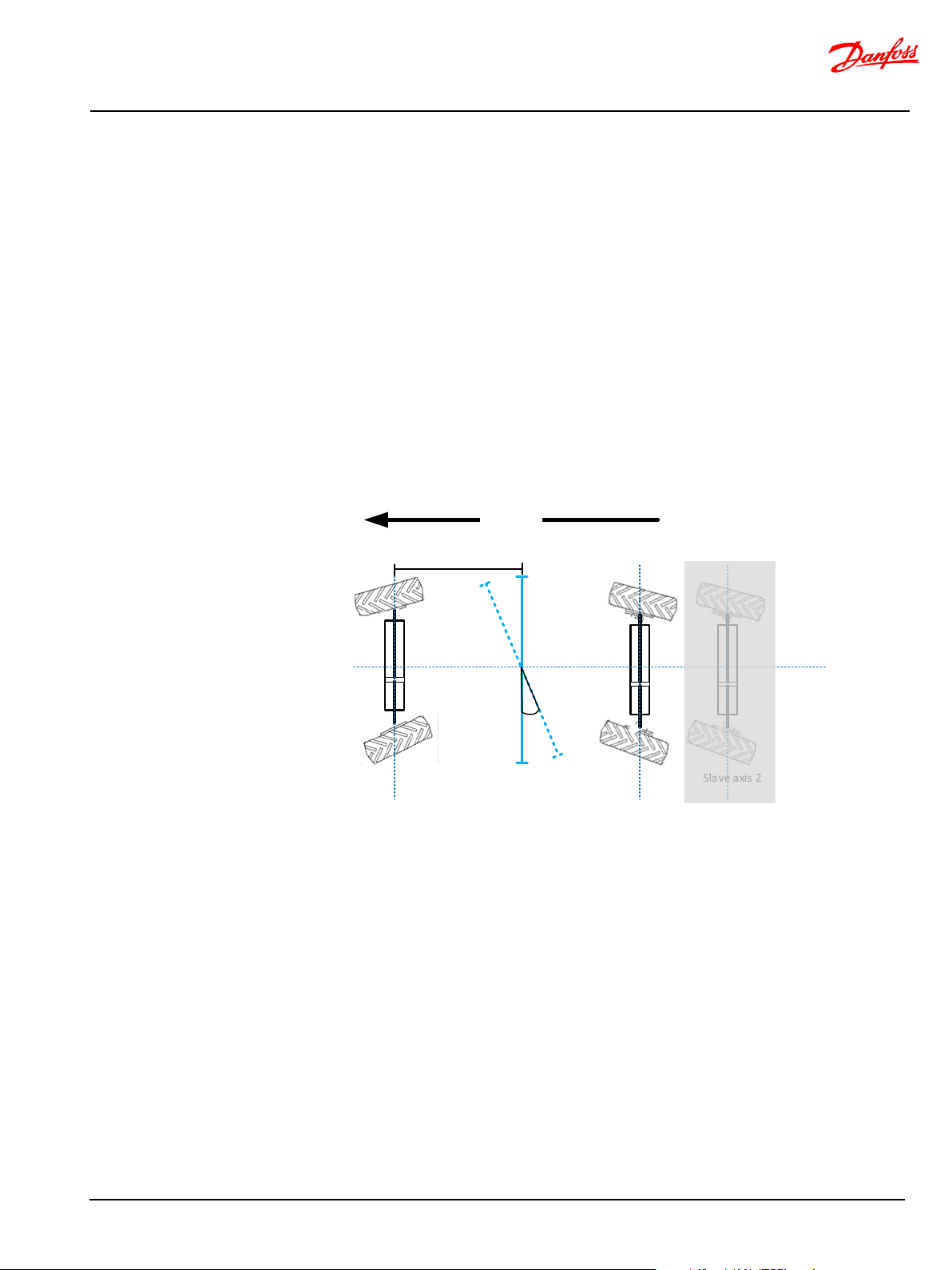
MultiAxis vehicle steering is adding steering functionality to have steering on one or more steering axis
than the master axis.
Throughout this document, and in referenced documentation, N-axis or NAXIS are used as
synonyms for MultiAxis steering mainly referencing one or more additional (n) “slave” axis.
Any possibly vehicle steering mode can be achieved with N-Axis steering by the N-Axis MMI command
CAN message, containing the Virtual Axis Position (VAP) and the Virtual Axis Angle (VAA). See Figure 1.
The data set, given by VAP and VAA, can result in steering modes such as:
• 2-wheel steering (normal)
• Round/4-wheel steering
• Crab steering
• Dog steering
• Customized steering modes
The steering modes can be altered dynamically and seamlessly by the operator during operation by
transmitting VAP and VAA data set which results in the requested steering mode.
BC321571012557en-000104 © Danfoss | Nov 2019 | 9
Figure 1 N-Axis steering variables VAP and VAA
The blue line is the Virtual Axis which can be shifted horizontally along the wheel base (VAP) and
angled relative to the wheel base (VAA). Shifting VAP to the physical slave axis position in a single slave
system will result in 2-wheel steering.
Page 10
MultiAxis-Steer technical information
N-Axis system principal
Wheel an gle
sensor
N-axis s lave
PVE D
-CLS
EHi Valve
Man machine
int erfac e
CAN bus
Slave axis
Mas ter axi s
Road mode
swi tch
Steering wheel
OSP
Wheel an gle
sensor
N-axis m aster
(OEM )
Veh icle speed
ON/ OF F
Service tool
ON/ OF F
Veh icle speed
Wheel an gle
sensor
N-axis s lave
PVED-CLS &
EHi valve
Man machine
int erfac e
CAN bus
Slave axis
Mas ter axi s
Road mode
swi tch
Steering wheel
OSP (E)
Wheel an gle
sensor
N-axis m aster
PVED-CLS &
OSPE/EHi valve
SASA
Service tool
ON/ OF F
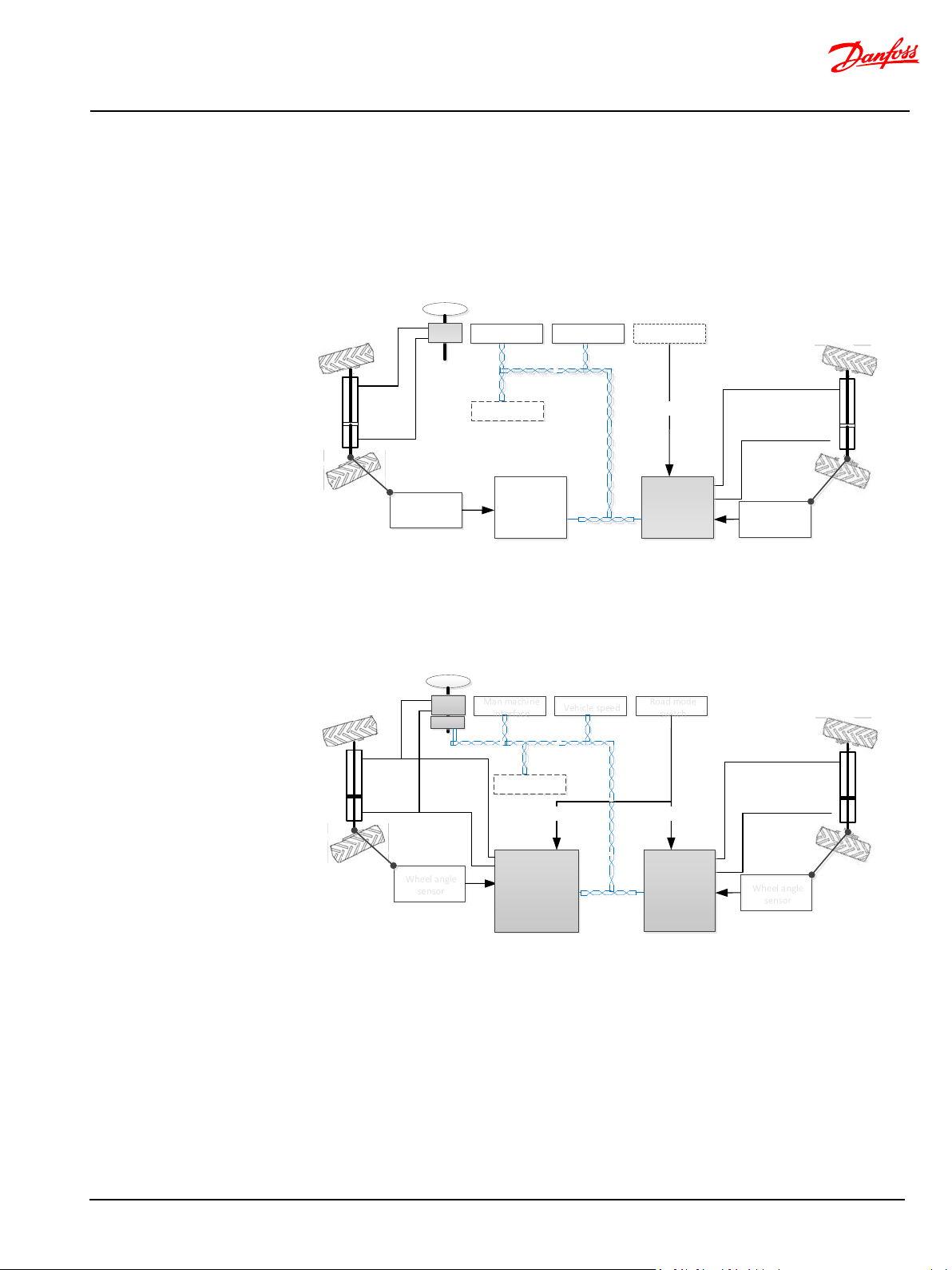
N-Axis system principal
A N-Axis slave steering sub-system may work with both a N-Axis master [hydrostatic] and N-Axis
master [electro hydraulic]. The below functions shall be performed by the system components outlined
in N-Axis system configurations.
N-Axis system configurations
N-Axis master [hydrostatic] steering system
In a N-Axis master, [hydrostatic] steering sub-systems, the master axis is actuated by a hydro-static
steering unit. All N-Axis master functions must be provided by the OEM controller working as N-Axis
master.
N-Axis master [electro hydraulic] steering system
In a N-Axis master [electro hydraulic] steering system, both the master and slave axis are electrohydraulic steering sub-systems e.g. by applying a PVED-CLS with an OSPE valve or a PVED-CLS with an
OSP and EHi inline valve enabling auto-guidance or other high level steering functionalities.
Refer to [PVED-CLS User manual ] for high-level electro-hydraulic steering master axis functionalites.
BC321571012557en-000104 © Danfoss | Nov 2019 | 10
Page 11

MultiAxis-Steer technical information
N-Axis system principal
N-Axis master functions
N-Axis slave function
An N-Axis master performs the following functions:
• Actuate the master steering axis
• Measure the master axis wheel angle and transmit it onto the CAN bus
• Transmit N-Axis master status information onto the CAN bus to the N-Axis slave
N-Axis master functionality shall be realized in the target system by the OEM or by applying a PVEDCLS in ‘N-Axis master’ mode (planned software extension).
Refer to [PVED-CLS MultiAxis-Steer communication protocol].
An N-Axis slave performs the following functions:
• Actuate the slave axis
• Receive N-Axis Man Machine Interface (MMI) commands
• Measure the slave axis wheel angle
• Execute slave-to-master wheel angle alignment initialization
• Perform closed-loop steering control of the slave axis cylinder
• Inputs for closed-loop steering control are:
o Master axis wheel angle
o Virtual Axis Position (VAP) from MMI
o Virtual Axis Angle (VAA) from MMI
o Wheel angle limitations from other N-Axis slaves (n > 1)
o Vehicle speed data
• Execute N-Axis safety related control functions
• On-road operation mode
• Apply wheel angle limitation on demand
• Apply self-centering (graceful degradation)
• Transmit N-Axis slave network status CAN message
• Auto-calibration functionality
Man Machine Interface (MMI)
The MMI performs the following functions:
The MMI functionality shall be realized in the target system by the OEM.
Refer to [PVED-CLS MultiAxis-Steer communication protocol].
Vehicle speed sensor
The vehicle speed sensor sub-system performs the following function:
The vehicle sensor sub-system shall be shall be realized in the target system by the OEM.
Refer to [PVED-CLS MultiAxis-Steer communication protocol].
Wheel angle sensor
A wheel angle sensor shall acquire the wheel angle of the front and slave axis respectively.
The wheel angle sensor may:
The vehicle sensor sub-system shall be shall be realized in the target system by the OEM.
Refer to [PVED-CLS MultiAxis-Steer communication protocol] for CAN based wheel angle sensors.
• Cyclically transmission of the N-Axis MMI control message
• Control of the N-Axis steering mode set-point (VAP and VAA)
• Control of wheel angle limit on-demand
• Aqcusition and transmission of the vehicle propulsion speed onto the CAN bus
• Redundant analog 0-5V with crossed output characteristic
• CAN based
BC321571012557en-000104 © Danfoss | Nov 2019 | 11
Page 12

MultiAxis-Steer technical information
N-Axis system principal
Road switch
The road switch performs the following functions in respect to slaves axis:
• Activate N-Axis slave steering
• De-activate N-Axis slave steering
More activation/de-activation options are possible:
Active de-energize (immediate)
Disable N-Axis slave steering for reaching a safe operation mode for public road usage.
PVED-CLS will remain powered and transmit status and sensor information on the CAN bus.
See [Road-switch de-power / de-energize architectures
ON/OFF switch interface - Active de-energize (immediate)] on page 41.
Active de-energize (automatic return to straight)
Disable N-Axis slave steering with auto-centering to straight and subsequent reaching a safe operation
mode for public road usage
PVED-CLS will remain powered and transmit status and sensor information on the CAN bus.
See [ON/OFF switch interface - Active de-energize (automatic return to straight)] on page 44.
Full electrical de-power/de-energize
Full electrically de-power/de-energize the N-Axis slave to assume a safe state. The PVED-CLS and valves
are not powered. No slave axis functionality is available.
See [ON/OFF switch interface - Full electrical de-power/de-energize] on page 45.
Zero-leakage de-power/de-energize architecture option
Applications which require lower rear axis drift while N-Axis is inactive or de-energized, require
additional zero-leakage check valves. See [Zero-leakage valve configuration (option)] on page 46.
Advise for system integrators
Important
For systems, where a road switch is required, it must be analysed if cylinder drift, while de-energzied, is
acceptable. If cylinder drift cannot be tolerated, additional check valves may be needed for zeroleakage performance.
Service tool
The service tool provides a mean to perform calibration and diagnostic during installation and
performs the following functions:
• The road switch is optional in N-Axis steering systems.
• The OEM system integrator shall take the decision on the need for a road switch based on the
hazard and risk analysis for the particular vehicle.
• Factors such as maximum vehicle speed, weights, vehicle use profiles may be part of the
considerations.
• The road switch may also operate on N-axis master [electro-hydraulic] steering systems.
• See [Safe state leakage performance] on page 20 for cylinder drift during de-activation.
The system integrator shall ensure that the PVED-CLS and valve sub-system are used in a
suitable mode while the vehicle is being used on public roads.
• Configure parameter settings
• Read out error codes
• Diagnostic
• Valve spool auto-calibration
• Wheel angle sensor calibration
• Perform manual calibrations
• Program multiple parameters
• Flash firmware
BC321571012557en-000104 © Danfoss | Nov 2019 | 12
Page 13

MultiAxis-Steer technical information
N-Axis system principal
=
nAxis master network message
Message content:
Master axis wheel angle
Operation mode/Safe state
indica tion
MMI
Master axis c ontroller Slave #1 Slave #2 Slave #3
=
nAxis MMI message
Message content: Placement of
virtual axis positi on VAP, virtual axis
anlgel VAA and enable/dis able N-Axis
wheel angle li mit"
=
nAxis slave network message
Message conten t:
Limiting slave (ID and WA Right)
Limiting slave (ID and WA Left)
Safe state indication
=
nAxis operational status message
Message conten t:
N-axis operatio n status
Calibration status
Safe state indication
CAN message
Function description
N-Axis MMI
The MMI message contains the VAP and VAA which sets the vehicle steering mode.
Refer to [PVED-CLS MultiAxis-Steer communication protocol].
N-Axis master net work message
The N-Axis master message contains the master axis steering angle and the operation
Refer to [PVED-CLS MultiAxis-Steer communication protocol].
N-Axis slave network message
The N-Axis slave network message(s) contains the identifier of the slave which has
Refer to [PVED-CLS MultiAxis-Steer communication protocol].
N-Axis master/slave operation
Primary and redundant master and slave(s) operation status message [STAT_MSG_OP]
N-Axis operation status messages are for information only.
N-Axis CAN network
CAN message data flow
Four levels of CAN messages are flowing in an N-Axis steering system.
Figure 2 N-Axis CAN message network
N-Axis CAN messages
A pre-configured wheel angle limit can be enabled/disabled by the MMI which will take
priority over other wheel angle limitations in the N-Axis.
The N-Axis MMI message is only received by the N-Axis slaves (one or more).
NAXIS MMI PRIMARY MESSAGE [NAXIS_MMI_P]
NAXIS MMI REDUNDANT MESSAGE [NAXIS_MMI_R]
mode or safe state indication.
NAXIS MASTER PRIMARY MESSAGE [NAXIS_MASTER_P]
NAXIS MASTER REDUNDANT MESSAGE [NAXIS_MASTER_R]
reached its wheel angle limit (R/L) and the operation mode or safe state indication from
that particular N-Axis slave.
Any N-Axis can at some point reach a wheel angle restriction which limits the entire NAxis steering behavior i.e. not allowing further N-Axis steering to the direction which has
reached a limit.
A slave shall receive and forward the received wheel angle limit from a slave or transmit
its own limit if this is the tightest wheel angle limit.
Note that the N-Axis slave network messages are only sent when the number of N-Axis
slaves is > 1.
NAXIS WHEEL ANGLE LIMIT PRIMARY MESSAGE [NAXIS_MWA_LIMIT_P]
NAXIS WHEEL ANGLE LIMIT REDUNDANT MESSAGE [NAXIS_MWA_LIMIT_R]
BC321571012557en-000104 © Danfoss | Nov 2019 | 13
status message
Operational status message from the master and the slaves. Status message on N-Axis
steering mode, calibration status and safe sate indication.
Page 14
MultiAxis-Steer technical information
N-Axis system principal
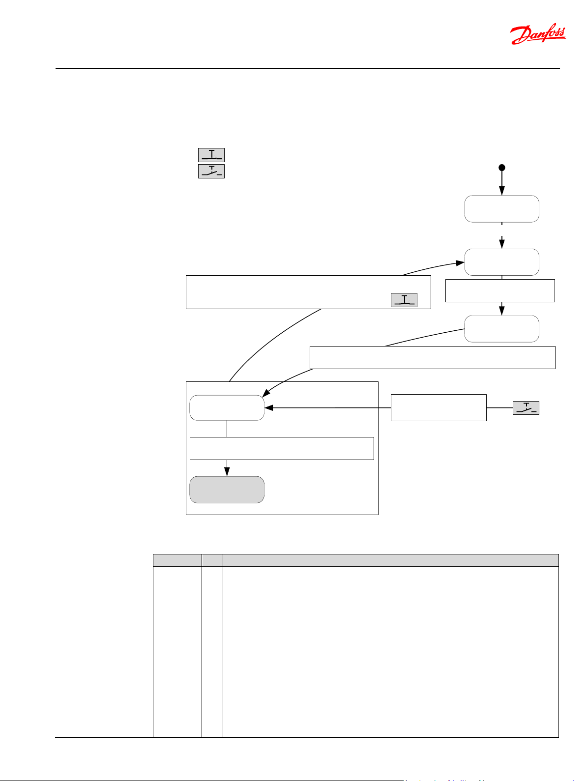
Pre
-operational
Power on
application start
Reset/soft
-reset
No error
|Wheel angle| <
NAXIS_PREOP_EXIT_WA_TOL_dDeg (P3910)
②
Initializat ion
POST
①
Condi tion 1: Vehicle speed <
[NAXIS_ONROAD_VSP_TRIG_MEAN_KMPH (P3908) - 0.5·NAXIS_ONROAD_VSP_T RIG_HYSTER_KMPH (P3907)]
OR
Condi tion 2: Road swit ch is present (P 3237=255) AND Road swit ch state is ‘N-axis act ive/ ON’
Operational
③
On-road stat e
④
On-road locked sta te
⑤
Condi tion 1: |wheel angle| ≤ NAXIS_ONROAD_MAX_WA_dDeg (P3909)
OR
Condi tion 2: NAXIS_ WHEELS_STRAIGHT _ROAD_SWITCH_TIMEOUT_10MS (P 3094)
Vehicle speed >
[NAXIS_ONROAD_VSP_TRIG_MEAN_KMPH (P3908) + 0.5·NAXIS_ONROAD_VSP_T RIG_HYSTER_KMPH (P3907)]
Ro ad swi tc h: N -axis ac tive /ON
Ro ad swi tc h: N -axis ina ct ive/OFF
Hig h-prio rity N-axis control
Road switch i s present (P3237=255)
AND
Road switch state is ‘N-axis in acti ve /OFF’
Power-on-self-tests are executed to ensure that the hardware, software and valves work to the
10 seconds after address claim, the application shall enter the safe state.
Prior to executing closed-loop slave axis position control in Operation state, the slave axis angles are
N-Axis operation
Operation state machine
Figure 3 N-axis operation state machine
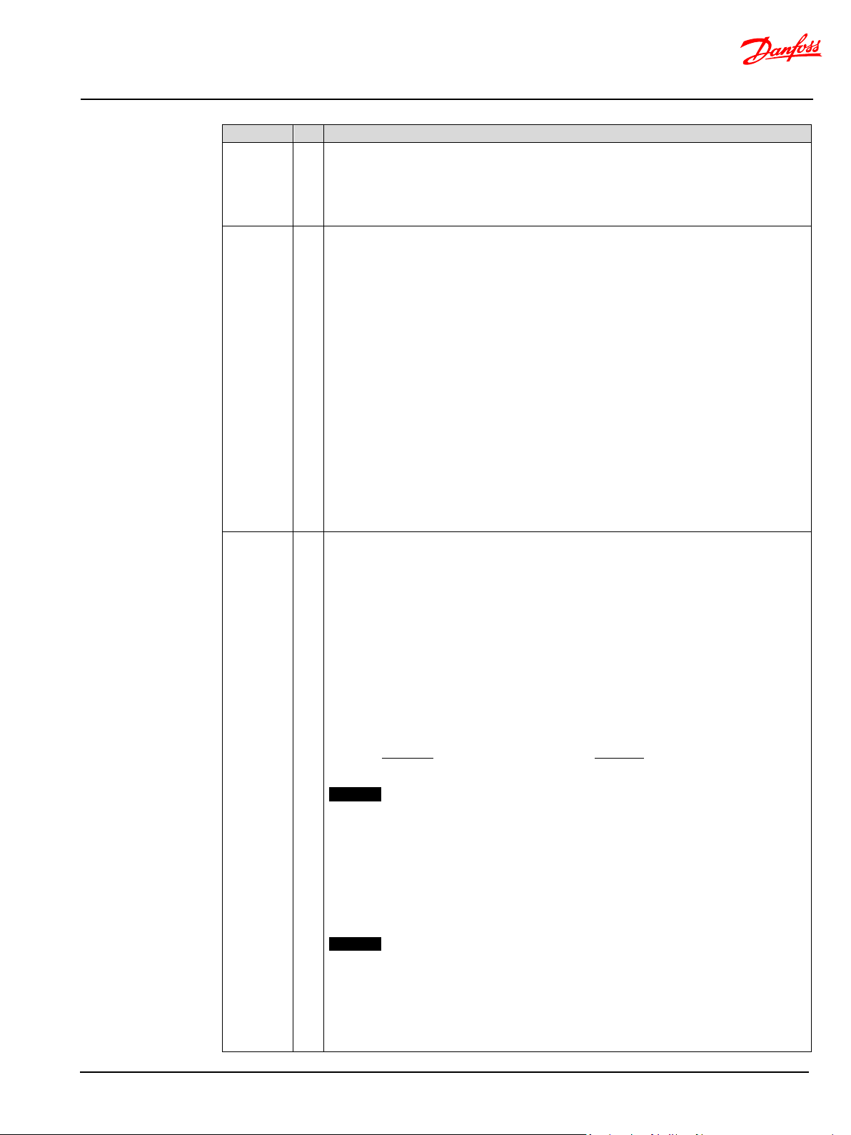
States
State # Description
Initialization
POST
1
specifications.
If a fault is detected the PVED-CLS enters the safe state (fail state) and issue a DTC on the CAN bus.
After transmitting the address claim message, the application shall wait up to 10 seconds for N-Axis
slave input signals:
MMI messages, vehicle speed CAN messages, analogue WAS signals, CAN based WAS signals (if
configured), N-Axis master messages, N-Axis master wheel angle limit messages (when the number
of slave axis > 1) and road switch signals.
Monitoring is applied on each signal/message upon reception of the first valid signal or message.
After a fixed 10 seconds time-out period, the software assumes that all signal and messages are
Preoperational
BC321571012557en-000104 © Danfoss | Nov 2019 | 14
present and starts individual monitoring of these. Should one or more sensors fail to be ready within
2
aligned to the master axis steering angle for the current N-Axis steering mode set-point (VAP, VAA).
Page 15
MultiAxis-Steer technical information
N-Axis system principal
State
#
Description
The alignment is performed by letting master axis steering motion work as a gate for closed-loop
parameter P3910. Hereafter the N-Axis resumes to operational state.
stable information status on displays etc.
On-road state is an intermediate state where the slave axis is controlled to its straight position. Once
The surrounding system shall take appropriate action in case the slave axis enters safe
position control of the N-Axis slave; the slave axis steering angle will not change position unless the
master axis is changing position similar to “inching” the slave axis to the correct position.
This operation is continued until the slave axis position is inside a tolerable range given by the
Operational 3 Active closed-loop control of the slave axis position.
The control parameters shall undergo tuning to achieve a controllable steering for any N-Axis
steering mode change.
The input for the closed-loop control algorithm is:
• Master axis wheel angle
• Virtual Axis Position (VAP) from MMI
• Virtual Axis Angle (VAA) from MMI
• Wheel angle limitations from other N-Axis slaves (n > 1)
• Vehicle speed data
The closed-loop control performance is configurable by the parameters listed in [Safe vehicle speed
dependent closed loop gain limitation].
Typically the closed-loop control of the slave axis is configured to approach a sole front axis steering
system (VAA=0 and VAP = slave axis position) proportionally to increasing vehicle speed.
The maximum vehicle speed where N-Axis operation shall revert to a sole front axis steering system
is set by parameter P3908. Exceeding this speed + 0.5·P3907 (half of the vehicle speed hysteresis
band) will result in a jump to on-road state.
The hysteresis band shall be configured to avoid state bouncing which may be useful for displaying
On-road
state
4
straight position is reached, the software automatically transits to ‘On-road locked state’ which is the
state suitable for higher vehicle speeds.
Two conditions trigger a transition to on-road state:
1) A transition from Operation state (described above)
2) Commanding ‘on-road’-mode by means of the manually operated road switch
(parameter P3237)
On-road state operation:
• Command straight position by forcing VAA is forced to 0 and VAP is forced to the slave
axis position (P3896).
• A timer (P3094) is started to open a time window in which the slave axis shall reach
straight position
Setting P3094 = 0 will, on switching to on-road mode, disable closed-loop slave axis operation and
result in an immediate transition to On-road locked state regardless of the slave axis position. No alarm
will be raised if the slave axis angle is not centered. This setting shall be used when the road switch
immediately cuts power to the cut-off solenoid valve and thus makes closed-loop control impossible.
Important The surrounding system shall observe the slave axis position and take appropriate action
in case the slave axis is not in a position which is suitable for operation at higher speeds.
Setting P3094 to a time (e.g. 5000ms) in which it can be expected that the slave axis has been steered
to the straight position, enables achieving automatic slave axis self-centering and transition to onroad locked state. If a road switch is present in the system (P3237=255), then cutting power to the cutoff solenoid valve shall be equally delayed e.g. by applying timed delay relays.
If timer P3094 (set to a non-zero value) times out and the slave axis is not inside a configured straight
range (P3909), then the N-Axis slave will enter safe state and issue a diagnostic trouble code.
Important
state.
Exit from on-road safe state:
• If the vehicle speed drops below P3908 – 0.5·P3907 (half of the vehicle speed hysteresis
band), the software will exit and resume N-Axis operation by jumping to Pre-operational.
• If the road switch is set to ‘N-Axis active/ON’
BC321571012557en-000104 © Danfoss | Nov 2019 | 15
Page 16

MultiAxis-Steer technical information
N-Axis system principal
State
#
Description
• If the road switch is set to ‘N-Axis active/ON’
On-road
locked state
5 In on-road locked state, both the EH proportional valve and the cut-off valve are de-energized, to
block steering flows to the slave axis. The hardware is powered but N-Axis closed-loop control is
suspended. Internal and external monitoring of the electronics and interfacing signals is active.
Sensors are sampled and data is broadcast onto the CAN bus.
The slave axis cylinder position is not monitored and purely hydro-mechanically fixed in its position.
For leakage considerations, see Zero-leakage valve configuration (option) on page 46.
Exit from On-road locked state:
• If the vehicle speed drops below P3908 – 0.5·P3907 (half of the vehicle speed hysteresis
band), the software will exit and resume N-Axis operation by jumping to Pre-operational.
BC321571012557en-000104 © Danfoss | Nov 2019 | 16
Page 17

MultiAxis-Steer technical information
N-Axis system principal
Pre-safe state enables the N-Axis system to fail gracefully.
Vehicle speed CAN message
Safe state is reached when the no flow is output to the slave axis steering cylinder.
spring force)
Co nidti on 1: |wheel angle|≤ NAXIS_ONROAD_MAX_WA_dDeg (P3909)
OR
Co nditi on 2: NAXIS_WHEELS_STRAIGHT_VSP_SAFESTATE_TIMEOUT_10MS (P3096)
Reset, soft-rese t, power-cycle
External failures
Pre-safe stat e
⑥
Safe st ate
⑦
Int erna l f ail ures
Co nidt ion 1: |wheel angle|≤ (P3909) On-R o ad t o O n -R oad -locked Max WA
OR
Co ndit ion 2: (P3096) Sl av e positi on with re spec t to mast er
Reset, soft-rese t, power
-cycle
External failures
Pre-safe stat e
⑥
Safe st ate
⑦
Int erna l f ail ures
Operation state machine – fault handling
States
State # Description
Pre-safe state 6
Safe state 7
On detecting any failure classified as ‘external’, the slave axis is steered to straight
whereafter the software jumps to safe state.
Operation in Pre-safe state:
• Command straight position by forcing VAA is forced to 0 and VAP is forced to
the slave axis position (P3896).
• A timer (P3096) is started to open a time window in which the slave axis shall
reach straight position.
If timer P3096 times out and the slave axis is not inside a configured straight range (P3909),
then the N-Axis slave will enter safe state.
Failures on the following signals are classified as external:
• N-Axis MMI CAN message
• N-Axis master network CAN message
• N-Axis slave network CAN message
•
The safe state is achieved by at least one of the below two actions:
• De-energizing the EH proportional valve (EH spool is pushed to neutral by a
spring force)
• De-energizing the cut-off valve (COV spool is pushed to closed position by a
BC321571012557en-000104 © Danfoss | Nov 2019 | 17
Page 18
MultiAxis-Steer technical information
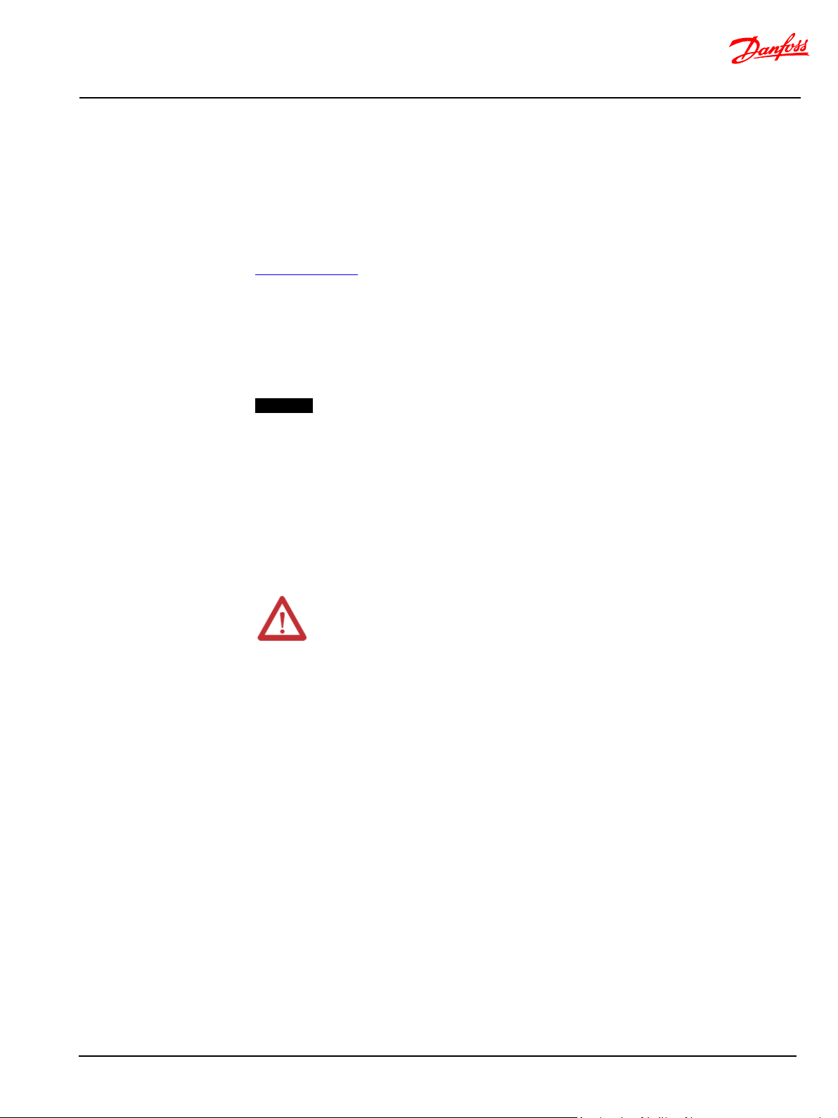
Functional safety
Functional safety
Certification (pending)
The PVED-CLS N-Axis steering valve controller is certified for use in off-road safety applications up SIL2
according to IEC 61508, PL d according to ISO 13849 and AgPL d according to ISO 25119.
Architectures for risk reduction up to SIL3/PL e/AgPL e is specified.
The certificate for the PVED-CLS valve controller can be found in the document PVED-CLS Functional
Safety Annex. The PVED-CLS Functional Safety Annex can be found on the Danfoss homepage:
www.danfoss.com
The certificate scope is for the generic PVED-CLS valve controller for use in safety-related applications
as follows; for off-road applications, safe electro-hydraulic steering is ensured by metering out a safe
steering flow as a function of selected steering mode, input steering command, vehicle speed and
steered wheel angle.
For on-road operation, functional safety is achieved by de-energizing the PVED-CLS valve controller.
Important
The certificate does not cover safe on-road system to SIL 3, PL e and AgPL e in its entirety as it requires
external circuitry, which is not in scope of the assessment.
The certification is not a guarantee for that the realized functional safety is sufficient for any machine.
The OEM system integrator is responsible for analyzing the hazard and risks for a particular machine
and evaluate if the risks are sufficiently reduced by the provided safety functions. The application of
the PVED-CLS and valve sub-system is subject for a separate safety life-cycle.
System integrator responsibility
Attention
It is within the responsibility of the OEM system integrator to:
• Having an organization that is responsible for functional safety of the system.
• Ensuring that only authorized and trained personnel perform functional safety related work.
• Choosing reliable components.
• Completing a system hazard & risk analysis and derive the required risk reduction targets.
• Reassessing the hazard & risk every time the system is changed.
• Ensuring that the derived risks are properly reduced by the safety functions provided by the
PVED-CLS valve controller.
• Certification and homologation of the entire system to the desired risk reduction level.
• Installation, set-up, safety assessment and validation of the interfacing sensor sub-systems.
• Parameter configuration of the application software in accordance with this safety manual.
• Validating that the safety functions reduce the risks as expected.
• Any related non-safety standards should be fulfilled for the application and its components.
• Verify the environmental robustness suitability of the PVED-CLS to installation in the final
system in its surrounding environment.
• Periodically inspect for errata information updates.
BC321571012557en-000104 © Danfoss | Nov 2019 | 18
Page 19
MultiAxis-Steer technical information
Functional safety
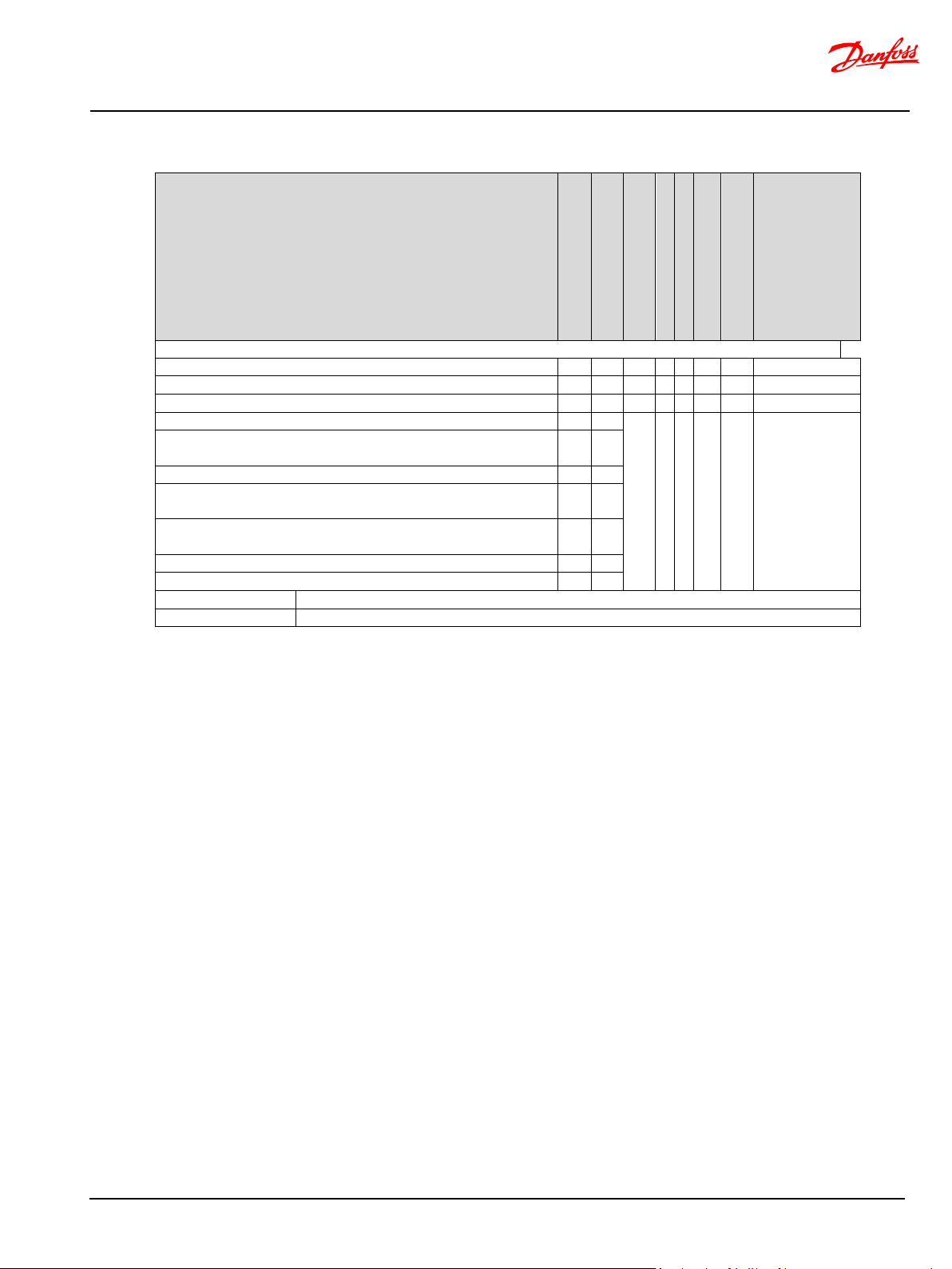
System/Sensor interface
Road switch Relay circuitry
Master wheel angle
N-Axis slave wheel
Vehicle speed sensor SIL2, PL d, AgPL d
SIL3, PL e, AgPL e
Safety function/safety related control function
Safe on-road mode / active de-energization
• • x On-road mode (no road switch installed)
• • • • x Safe EH N-Axis steering
• • • • x Safe vehicle speed dependent virtual axis position (VAP) limit
Safe vehicle speed dependent virtual axis position (VAP) change
rate.
Safe vehicle speed dependent virtual axis angle (VAA) limit.
Safe vehicle speed dependent virtual axis angle (VAA) change
rate.
Safe vehicle speed dependent closed-loop control gain
limitation
Safe vehicle speed dependent wheel angle set-point limitation
Safe N-Axis steering angle initialization (pre-operational).
•
Element of safety function
x
Highest achievable risk reduction
Safety function overview
N-Axis MMI message
• • • • x
BC321571012557en-000104 © Danfoss | Nov 2019 | 19
Page 20

MultiAxis-Steer technical information
Functional safety
Safety function
Fault reaction/risk
mitigation
Safety response time
Safe on-road mode / active de-energization
(immediate)
Functional safety specification
Safe state
N-Axis steering operation while in safe state
Safe state leakage performance
The safe state is achieved when no steering flow is provided to/from the steering cylinder and the NAxis slave cylinder is fixed at its position.
Achieving the safe state relies on a de-energize/fail safe princicple.
To reach the safe state, all safety controlled outputs, i.e. solid state power switches controlling the EHi
valve, are de-energized.
For the EHi valve, the safe state is achieved by one or both of the following states:
• The EH-valve main spool of the EH steering valve is in neutral position.
• Cut-off valve spool is in blocked position.
If the PVED-CLS hardware or software detects a failure or fails to function, the safe state will be
demanded. One or more diagnostic trouble codes related to the detected failure will be broadcast on
the CAN bus. Refer to [Diagnostic Trouble Codes] on page 96.
If an N-Axis steering system enters safe state, N-Axis angle(s) closed-loop control of all N-Axis stops,
and the respective N-Axis slave steering angles will freeze.
The operator will detect this as a different vehicle steering behavior when steering the vehicle. The
difference in perceived steering behavior will increase with the operators steering input command
change. This property shall be considered for ensuring vehicle steering controllability in N-Axis safe
state.
Important
The surrounding system shall take appropriate action if an N-Axis slave enters safe state e.g. raising the
attention at the operator by means of an acoustic and visual alarm.
In the safe state the cylinder is isolated and fixed in position. External forces on the steered wheels may
cause slow cylinder position drift due to hydraulic leakage.
The maximum leakage is 150ml/min at 150bar cylinder port pressure at ~21cSt (Tellus 32, 50°C).
In application where ~zero cylinder drift is required, additional pilot-operated check valves shall be
considered on the cylinder ports. See page 46.
Reset and recovery from safe state
Safety function response time
BC321571012557en-000104 © Danfoss | Nov 2019 | 20
The PVED-CLS cannot leave the safe state by normal application interaction but requires a reset.
Resetting the PVED-CLS valve controller from safe state can be done by any of the below methods:
• Power-cycling battery supply to the PVED-CLS
• Performing a soft-reset by J1939 CAN command [PVED-CLS MultiAxis-Steer communication
protocol].
• Perform a jump to and out of boot-loader via KWP2000 start and stop diagnostic session
services [PVED-CLS KWP2000 protocol].
All the above-mentioned methods to reset the PVED-CLS from safe state, will force a full Power-on-SelfTest (POST) of the PVED-CLS and valve.
The safety response time is defined as the period of time between a failure is first observed by the
diagnostics and the time by which the safe state has been achieved, e.g. de-energizing the solenoid
valves to bring the valve spool(s) within the hydraulic deadband (no steering flow output).
Safe on-road mode 70 ms
Page 21

MultiAxis-Steer technical information
Functional safety
Safe EH-steering / N-Axis closed loop
Control loop time: 10ms
Monitoring
mitigation
Monitoring response time
EHi valve
Internal hardware and
software
Safe state
160 ms
External sensor monitoring
(note 1)
160 ms
Valve main spool monitoring
250 ms (note 2)
Solenoid valve connection
monitoring
560 ms
cylinder position control
The safety related control function ‘Safe EH-steering’ is executed every 10ms and executes safe closedloop cylinder position control.
The reaction time for the EHi valve spool to reach neutral position (safe state) from full stroke is
typically 60ms for normal working temperature/viscosity.
The ‘Safe on-road mode’ is demanded by the road switch and switches to safe on-road mode within a
10ms control loop period (react and switch off valve drivers) plus the time it takes for the valve spool to
close the steering flows (maximum spool stroke).
Monitoring function response time
The monitoring funciton response time is defined as the period of time between a failure is first
observed by the diagnostics and the time by which the safe state has been achieved, e.g. deenergizing the solenoid valves to bring the valve spool(s) within the hydraulic deadband (no steering
flow output).
The reaction time for the EHi valve spool to reach neutral position (safe state) from full stroke is
typically 60ms for normal working temperature/viscosity.
Safe state 160 ms
Fault reaction/risk
Note 1: Sensor CAN message time-outs are configurable which has a direct impact on the fault reaction
time.
Note 2: The spool monitoring fault reaction times are valid when the hydraulics has reached normal
working temperature/viscosity.
BC321571012557en-000104 © Danfoss | Nov 2019 | 21
Page 22

MultiAxis-Steer technical information
Functional safety
PVED-CLS
Ext. Primary
sensor
Ext.
Redundant
sensor
EH-valve
Cut-off valve
Safety parameter
Specification
Description
SIL
2
characteristics.
PFH
5.77∙10-8 [1/h]
Component type
B
SFF
98 %
DC
97 %
Architecture /category (IEC 61508)
1oo2
Proof test interval/mission time
20 years
Reliability handbook
Siemens SN29500
Calculations are performed at an average
temperature equal to 80 °C
Fault exclusion
Mechanical valve
valve, cut-off spool)
block the EH steering flow to the cylinder.
OSPE EH-valve test
On-line testing
Direct monitoring by a LVDT sensor.
OSPE Cut-off valve test
Intermittent full
stroke test.
Indirect monitoring by test pilot pressure test. Test
road mode and
prior to executing off-road steering functionality.
AgPL/PL
d
Maximum achievable performance level
MTTFd per channel
36 years
ISO 13849, ISO 25119
DCavg per channel
97 % / (95 %)
ISO 13849 / (ISO 25119, lowest of the two channels)
PVED-CLS and valve sub-system
3
ISO 13849, ISO 25119
2
When using with EHPS valve. ISO 13849, ISO 25119
CCF analysis
>65
ISO 13849, ISO 25119
Software Requirement Level
SIL2 / SRL3
IEC 61508, ISO 13849 / ISO 25119
Systematic Capability (SC)
2
IEC 61508
N-Axis safe EH steering
Safe EH-steering / N-Axis closed loop cylinder position control
The safety functions of the N-Axis steering system is to provide :
• “Safe EH steering” (in general) and
• “Safe N-Axis on-road mode”
in multiple axis steering systems.
The probabilistic calculations are based on FMEDA calculations according to IEC 61508.
The calculations are valid for off-road application mode and related safety functions.
All safety functions and related hardware are included.
Sensor sub-systems as well as road switch are not included as it depends on the system.
The CAN bus contributes less than 1% of SIL2 due to the applied safety protocol and is thus omitted in
safety related calculations.
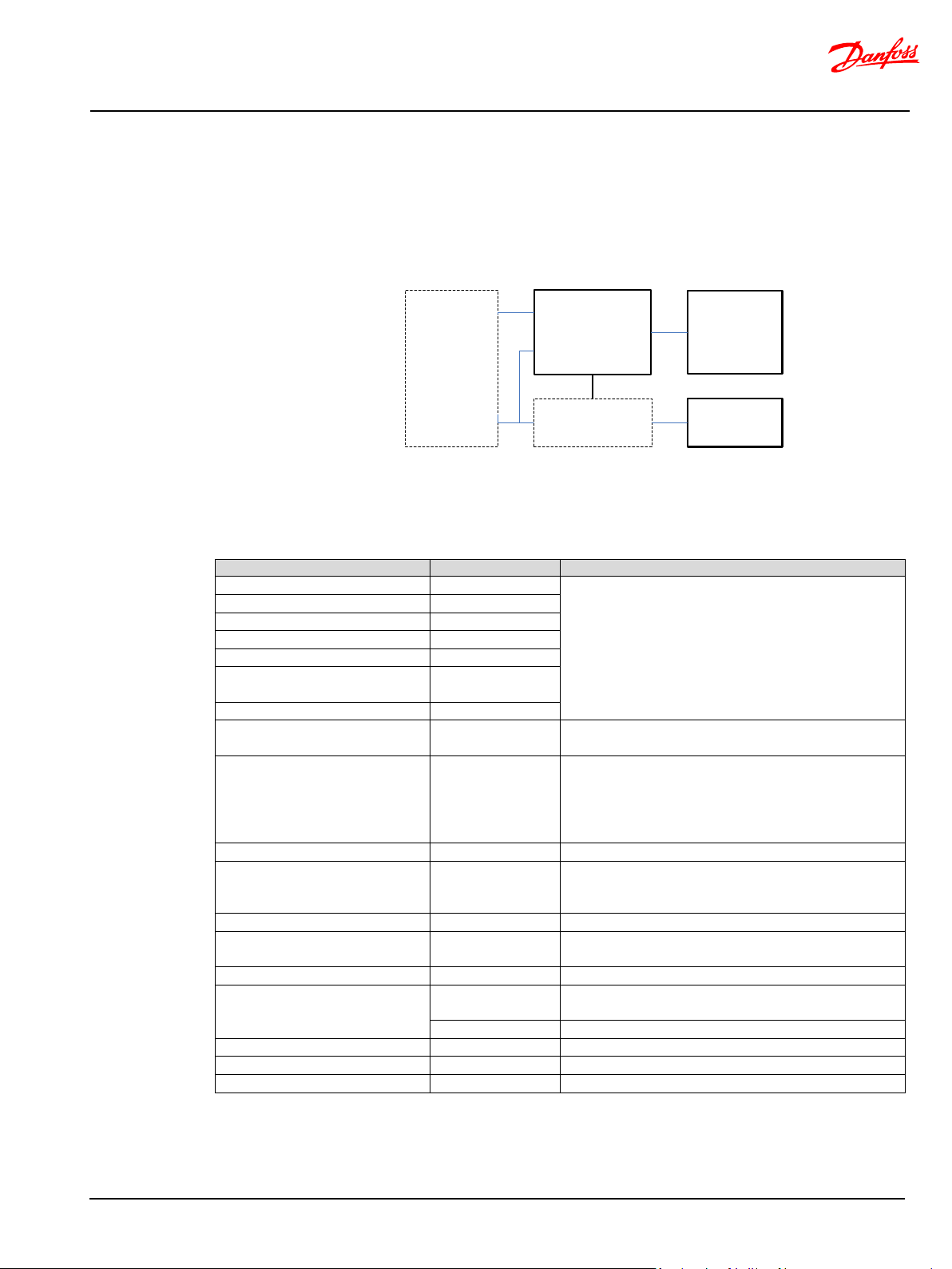
Category
Figure 4 Simplified reliability block diagram
IEC 61508 ed. 1
The FMEDA calculation assumes the use of
redundant analogue WAS with inverted
parts (EH-valve, EHmain spool, cut-off
On demanding the safe state, both valves do not
fail simultaneously. At least one valve will always
performed on changing to off-
Source: Danfoss PVED-CLS/OSPE/EHPS/EHi FMEDA.
BC321571012557en-000104 © Danfoss | Nov 2019 | 22
Page 23
MultiAxis-Steer technical information
Functional safety
PVED-CLS
Road switch
EH-valve
Cut-off valve
External logic
Safety parameter
Specification
Description
SIL
2
interface.
PFH
6.08∙10-8 [1/h]
Component type
B
SFF
98 %
DC
97 %
Architecture /category (IEC
61508)
1oo2
Proof test interval/mission time
20 years
Reliability handbook
Siemens SN29500
Calculations are performed at an average temperature
equal to 80 °C
Fault exclusion
Mechanical valve
main spool,
off spool)
On demanding the safe state, both valves do not fail
test.
OSPE EH-valve test
On-line testing
Direct monitoring by a LVDT sensor.
OSPE Cut-off valve test
Intermittent full
stroke test.
Indirect monitoring by test pilot pressure test. Test
executing off-road steering functionality.
AgPL/PL
d
Maximum achievable performance level
MTTFd per channel
57 years
Optimized value for this Safety function.
ISO 13849, ISO 25119.
DCavg per channel
97 % / (95 %)
ISO 13849 / (ISO 25119, lowest of the two channels)
PVED-CLS and valve sub-system
3
When using with OSPE, EHi-E or EHi-H valve. ISO 13849,
ISO 25119
2
When using with EHPS valve. ISO 13849, ISO 25119
CCF analysis
>65
ISO 13849, ISO 25119
Software Requirement Level
SIL2 / SRL3
IEC 61508, ISO 13849 / ISO 25119
Systematic Capability (SC)
2
IEC 61508
Safe N-Axis on-road mode / N-Axis active de-energize (shut-off)
Additional circuitry is needed for systems where the hazard & risk outcome points to a higher risk
reduction (avoiding unintended steering) than the PVED-CLS can provide. External logic shall be
installed to have the PVED-CLS powered while being in a de-energized state.
The probabilistic calculations are based on FMEDA calculations according to IEC 61508.
Non-relevant safety parts in the PVED-CLS are excluded in the calculation of the safety related
specifications.
Figure 5 Simplified reliability block diagram
The below data is valid for the safe on-road switch channel containing the PVED-CLS and solenoid
valve bridge. For specification on the electro-mechanical channel see section Safety requirements for
additional circuitry for SIL3/PL e on page 48.
IEC 61508 ed. 1
The FMEDA calculation assumes the use of redundant
analogue WAS with inverted characteristics.
All circuitry including circuitry for diagnostics is
included except LED, temperature sensor and JTAG
parts (EH-valve,
EHcut-off valve, cut-
simultaneously. At least one valve will always block the
EH steering flow to the cylinder. Fault accumulation is
addressed by OSPE EH-valve and OSPE Cut-off valve
performed on changing to off-road mode and prior to
Category
Source: Danfoss PVED-CLS/OSPE/EHPS/EHi FMEDA.
BC321571012557en-000104 © Danfoss | Nov 2019 | 23
Page 24

MultiAxis-Steer technical information
Functional safety
VAP
VAA
M MI CAN
monitoring
WAS CAN
monitoring
WAS Analog
monitoring
Safe v ehic l e speed
d epend ent
VA P
limit
Safe v ehic l e speed
d epe nd ent V A P
cha nge ra te limit
Safe v ehic l e speed
d epend ent
VAA
limit
Safe v ehic l e speed
d epe nd ent V A A
cha nge ra te limit
Whe el angle limit on demand (on/off)
N-axi s sl av e
WA s et
p oint
cal cula tio n
Safe v ehic l e
spe ed
d epend ent
whe el a n gle s et -
point limitation
Safe v ehic l e speed
d epe nd ent c l os ed -l oop
control gain limitation
Cali bration
+
-
∫
G
Cali bration
Veh ic le s pe ed
C AN m on i to ri n g
WAS_P
WAS_R
AD1
AD2
M MI_ P
M MI_ R
VS P_P
VS P_R
P323 9
Fro nt ax i s whee l angl e
P3923
Ca lcu la t e fl ow
com man d
Fl ow
com man d to
spool set-
p oi nt tra nsfe r
fu nct ion
Ca lcu la t e l im it ed
fl ow c o mma nd as
function of fr ont axis
steer in g s p eed
PRE _OPE RATI O NAL/
N-AXIS OPERATIONAL
SVC
N-axis master
C AN m on i to ri n g
MAS TER_P
MAS TER_R
N-axi s s lave
C AN m on i to ri n g
MWA_LIMIT_P
MWA_LIMIT_R
N
-ax i s netw ork – whe el an gle lim itat ion fro m ot he r sl aves
Ext ern al
i nte rfac e
N-Axis safety related control functions
Figure 6 N-Axis EH safe steering block diagram
Blue blocks ( ) provide a link to the related chapter
Safe vehicle speed dependent Virtual Axis Position (VAP) limit
Realizing a safe MMI interface
Operation
BC321571012557en-000104 © Danfoss | Nov 2019 | 24
The safety related control function ‘Safe vehicle speed dependent Virtual Axis Position limit’ is an
instance of the safety functions for realizing a safe N-Axis MMI interface and work in a coordinated
fashion with
• [Safe vehicle speed dependent Virtual Axis Position (VAP) change rate],
• [Safe vehicle speed dependent Virtual Axis Angle (VAA) limit] and
• [Safe vehicle speed dependent Virtual Axis Angle (VAA) change rate].
A correctly configured safe MMI interface will allow any random VAP and VAA input value and change
rate while maintaining controllable N-Axis operation. No unintended change will lead to loss of
steering controllability.
The N-axis MMI interface can in such a case be regarded as non-critical for safe N-Axis operation.
The received VAP set-point is limited in accordance with a programmable safe VAP range envelope.
This may be useful in advanced N-Axis steering modes where VAP can be changed dynamically during
N-Axis operation and where there is no expectation to the VAP set-point. In such cases, a safe VAP
envelope can be configured.
The safe VAP range is configurable as a three-piece linear characteristic as shown in Figure 8. The
software performs linear interpolation to calculate the limited VAP set-point which is used by the NAxis control algorithm.
Page 25

MultiAxis-Steer technical information
Functional safety
Mast er a xis
Slave axis
P3896 [ mm]
P3898 [ mm]
(+P3864 [mm], 0 [kmph])
(-P3864 [m m], 0 [kmph])
(+P3866 [mm], P3870 [kmph])
(-P3866 [m m], P3870 [kmph])
(-P3868 [m m], P3871 [kmph])
(+P3868 [mm], P3871 [kmph])
N-Axis Virtual Axis Po sition Clamp
Vehicle Speed
P3864
P3870
P3866
P3868
P3871
0
1
2
Address
Name
Unit
Description of parameter
Clamp the Virtual Axis Position at vehicle
value (P3864)
Clamp the Virtual Axis Position at vehicle
value (P3866)
Clamp the Virtual Axis Position at vehicle
value (P3868)
Parameters
The received VAP is limited to the range defined by the envelope shown in Figure 8.
P3864
Figure 7 Safe vehicle speed dependent Virtual Axis Position (VAP) limit operation
Figure 8 Safe vehicle speed dependent VAP range envelope
N-Axis - Virtual axis position clamp at
vehicle speed 0
speed 0 to the range defined by N-Axis
mm
center postion (P3898) +/- this
BC321571012557en-000104 © Danfoss | Nov 2019 | 25
P3866
P3868
N-Axis - Virtual axis position clamp at
vehicle speed 1
N-Axis - Virtual axis position clamp at
vehicle speed 2
speed 1 to the range defined by N-Axis
mm
center postion (P3898) +/- this
speed 2 to the range defined by N-Axis
mm
center postion (P3898) +/- this
Page 26

MultiAxis-Steer technical information
Functional safety
N-Axis - Vehicle speed 1 for virtual
axis position clamp
Vehicle speed 1 for Virtual Axis Position
clamp
N-Axis - Vehicle speed 2 for virtual
axis position clamp
Vehicle speed 2 for Virtual Axis Position
clamp
Slave position with respect to the
master
Virtual axis mean position with
respect to the master
Virtual axis mean position with resoect to
the master
P3870
P3871
P3896
P3898
Note: The PVED-CLS performs a plausibility check at start-up on all parameters according to the
following rule: P3864 ≥ P3866 ≥ P3868 AND P3870 < P3871
Parameter tuning guideline
Scenario 1: Advanced N-Axis steering - dynamic changing VAP during operation
The ‘VAP clamp at vehicle speed 0 kmph’ -range (P3864) is typically set to the maximum possible VAP
set-point for the vehicle. This value is often determined by the vehicle geometry and the desired
maximum turning radius in N-Axis steering mode at low speeds.
At higher vehicle speeds, it may be desired to change the N-Axis steering to a mode which provides
better steering stability and controllability at higher speeds. This may be achieved by moving the
virtual axis position towards the defined NAXIS_VA_MEAN_POSITION_MM (P3898) as the vehicle speed
increases.
The ‘Virtual Axis Position clamp at vehicle speed VSP1 and VSP2’-ranges (P3866, P3868) shall
progressively made smaller. The resulting VAP set-points are expected to follow this trend.
Setting the ‘Virtual Axis Position clamp at vehicle speed VSP2’-range (P3868) to 0 will clamp any non-0
VAP set-point at vehicle speed = VSP2 (P3871) to 0. Consequently, the clamped VAP set-point will be
equal to the NAXIS_VA_MEAN_POSITION_MM (P3898). If in addition to this the
NAXIS_VA_MEAN_POSITION_MM is identical to the physical slave position the steering behavior will
resemble a traditional two-wheel steering system.
Tests shall be performed to validate the safety of the settings.
Scenario 2 Advanced N-Axis steering – static VAP during operation
For N-Axis steering systems where only one N-Axis steering behavior, e.g. round-steering, is desired,
the MMI may send a static VAP.
If the static VAP is safe at all vehicle speeds, then P3864, P3866, P3868 can be set equal to the expected
static VAP set-point and P3870 and P3871 can be set to the maximum allowed vehicle speed in N-Axis
mode.
If the safety validation tests indicate that N-Axis steering is not safe at all vehicle speeds, then adjust
P3864, P3866, P3868 until steering controllability is reached at all vehicle speeds.
Operation when number of slaves > 1
P3864, P3866, P3868, P3780, P3871 and P3898 shall be set to the same value in all N-Axis slaves.
kmph
kmph
mm Slave Position with respect to the master
mm
BC321571012557en-000104 © Danfoss | Nov 2019 | 26
Page 27

MultiAxis-Steer technical information
Functional safety
Master axis
Slave axis
(P3 87 2 [ mm/ s], 0 [ kmph ]
(P3 87 6 [ mm/ s], P38 79 [kmp h]
t= 0
(P3 87 4 [ mm/ s], P38 78 [kmp h]
VA P ②
VA P ①
VAP se t-poi nt
VAP s et-p oi nt ch ang e ste p fro m ①→ ②
Safe vehicle speed dependent Virtual Axis Position (VAP) change rate
With the VAP change rate it is possible to set up a relaxed system at high vehicle speed so that any
change from the operator will be accepted but will happen at a slow rate moving the Virtual Axis
position from one point to another more relaxed.
Realizing a safe MMI interface
The safety related control function ‘Safe vehicle speed dependent Virtual Axis Position change rate’ is
an instance of the safety functions for realizing a safe N-Axis MMI interface and works in a coordinated
fashion with:
• [Safe vehicle speed dependent Virtual Axis Position (VAP) limit]
• [Safe vehicle speed dependent Virtual Axis Angle (VAA) limit]
• [Safe vehicle speed dependent Virtual Axis Angle (VAA) change rate]
A correctly configured safe MMI interface will allow any random VAP change rate while maintaining a
stable and controllable N-Axis operation.
The N-Axis MMI interface can in such case be regarded as non-critical for safe N-Axis operation after
safety validation testing.
Operation
The safety related control function ‘Safe vehicle speed dependent Virtual Axis Position (VAP) change
rate’ operates on the output of safety related control function [Safe vehicle speed dependent Virtual
Axis Position (VAP) limit]. See also [
A VAP set-point change is limited in accordance with a programmable ‘safe VAP change rate’ -range
shown in [
Figure 10 Safe vehicle speed dependent VAP change range envelop]. This may be useful for advanced N-
Axis steering modes where the VAP set-point can be changed dynamically during N-Axis operation. In
such cases, a safe VAP change rate range can be configured while allowing some freedom to the
generation of the VAP set-point.
The safe VAP change rate range is configurable as a three-piece linear characteristic. The software
performs linear interpolation to calculate the limited VAP set-point change rate limit at any vehicle
speed.
Figure 6 N-Axis EH safe steering block diagram].
BC321571012557en-000104 © Danfoss | Nov 2019 | 27
Figure 9 Safe vehicle speed dependent Virtual Axis Position (VAP) change rate operation
Page 28
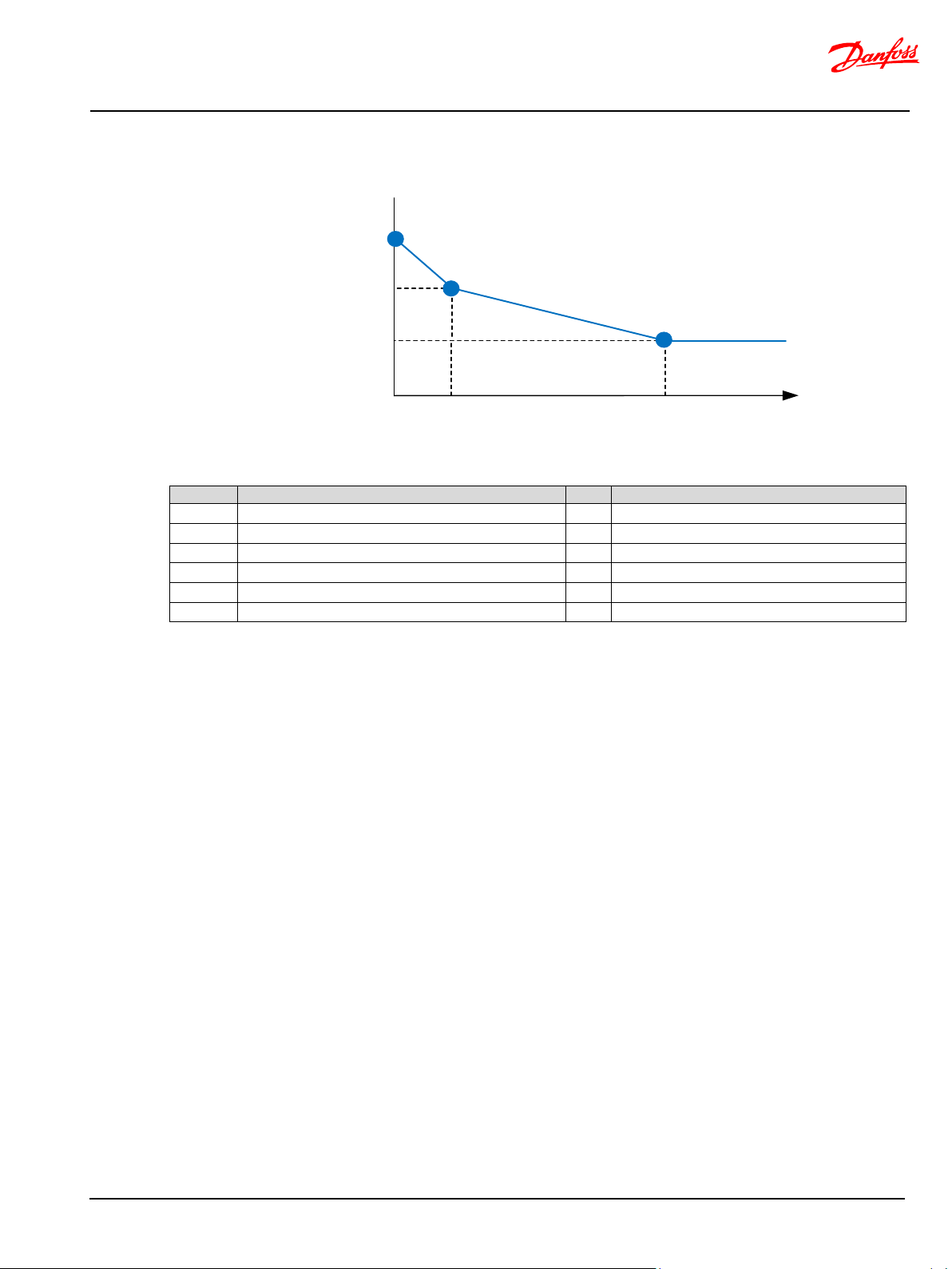
MultiAxis-Steer technical information
Functional safety
N-Axis Virtual Axis Po sition change rate [mm/s]
Vehicle Speed
P3872
P3878
P3874
P3876
P3879
0
1
2
Address
Name
Unit
Description of parameter
P3872
N-Axis - Virtual axis position ramp at vehicle speed 0
mm/s
Virtual Axis Position ramp at Vehicle speed 0.
P3874
N-Axis - Virtual axis position ramp at vehicle speed 1
mm/s
Virtual Axis Position ramp at Vehicle speed 1
P3876
N-Axis - Virtual axis position ramp at vehicle speed 2
mm/s
Virtual Axis Position ramp at Vehicle speed 2
P3878
N-Axis - Vehicle speed 1 for virtual axis position ramp
kmph
Vehicle speed 1 for Virtual Axis Position ramp
P3879
N-Axis - Vehicle speed 2 for virtual axis position ramp
kmph
Vehicle speed 2 for Virtual Axis Position ramp
Parameter
Parameter tuning guideline
Figure 10 Safe vehicle speed dependent VAP change range envelop
Note: The PVED-CLS performs a plausibility check at start-up on all parameters according to the
following rule: P3872 ≥ P3874 ≥ P3876 AND P3878 < P3879
Scenario 1: Dynamically changing VAP during operation
Changing the VAP will alter the vehicle steering mode. A VAP change is typically easier to control at
lower speeds than at higher vehicle speeds. The below tuning guideline may serve as a starting point
for system integrators.
Refer to Figure 10 Safe vehicle speed dependent VAP change range envelop:
1. Adjust point ⓪: The possible range at which the VAP can change is given by ±P3864 (refer to
[Safe vehicle speed dependent Virtual Axis Position (VAP) limit]). Observe, while toggling the VAP
set-point between the outer range values ±P3864, that that the steering mode changes at a
controllable speed for all front axis steering angles. Tune P3872 as high as possible while achieving
the desired steering mode change response when the vehicle is at still-stand.
2. Adjust point ②: As a starting point, set P3876 to e.g. 100 (10mm/s) and set P3879 to the
maximum vehicle speed at which N-axis operation is allowed. The possible range of VAP set-points
are limited (refer to [Safe vehicle speed dependent Virtual Axis Position (VAP) limit]). Observe,
while toggling the VAP set-point between the maximum possible limited values, that that the
steering mode changes at controllable speed for all front axis steering angles. Tune P3876 as high
as possible while achieving the desired controllable steering mode change response while driving
at P3879 kmph.
3. Adjust point ①: As a starting point, set P3878 to 0.5 x P3879 and set P3874 to 0.5 x P3872. The
possible range of VAP set-points are limited by [Safe vehicle speed dependent Virtual Axis Position
(VAP) limit)]. Observe, while toggling the VAP set-point between the maximum possible limited
values, that that the steering mode changes at a controllable speed for all front axis steering
angles. Tune P3874 as low as possible while achieving the desired controllable steering mode
change response while driving at P3878 kmph.
BC321571012557en-000104 © Danfoss | Nov 2019 | 28
Page 29

MultiAxis-Steer technical information
Functional safety
Scenario 2: Fixed VAP during operation
For N-axis steering systems where a constant VAP set-point is applied during operation, the MMI shall
transmit a fixed VAP set-point. Limiting the rate of change for this VAP is only relevant to control an
unintended VAP change. Set P3872, P3874 and P3876 to e.g. 100 [mm/s] to achieve a slow changing
steering system in the event of receiving an unintended VAP set-point.
P3878 and P3879 are not relevant and shall be set to valid values.
Scenario 3: Disable VAP change rate limiting
VAP change rate limitation can be disabled by setting P3872, P3874 and P3876 to 10000.
P3878 and P3879 are not relevant and shall be set to valid values. Any limited VAP set-point change
will take immediate effect.
Operation when number of slaves > 1
P3872, P3874, P3876, P3878, P3879 shall be set to the same value in all N-Axis slaves.
Important
• P3872, P3874, P3876 shall be set to values > 0. VAP rate change limitation will not work when
0 is used.
• The parameter tuning guideline may not apply to all steering systems.
BC321571012557en-000104 © Danfoss | Nov 2019 | 29
Page 30
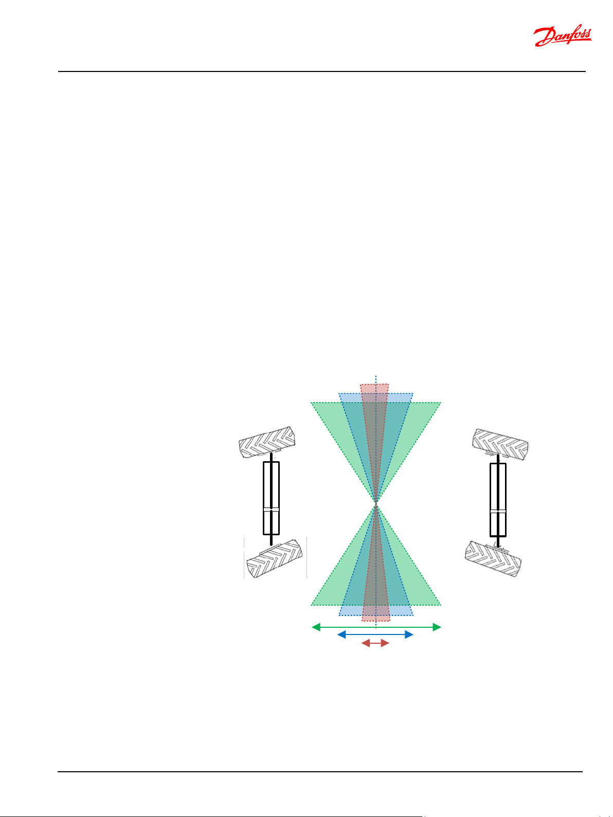
MultiAxis-Steer technical information
Functional safety
Maste r axis
Virtual
Axis Angle
Slave axis
(+P 3880 [dDeg], 0 [km ph])
(-P38 82 [d Deg], P 3886 [kmph])
(-P38 84 [d Deg], P 3887 [kmph])
(-P38 80 [d Deg], 0 [km ph])
(+P38 82 [dD eg], P38 86 [kmph])
(+P38 84 [dD eg], P38
87 [kmph])
Virtual Axis Position
Safe vehicle speed dependent Virtual Axis Angle (VAA) limit
Realizing a safe MMI interface
The safety related control function ‘Safe vehicle speed dependent Virtual Axis Angle limit’ is an
instance of the safety functions for realizing a safe N-Axis MMI interface and work in a coordinated
fashion with
• [Safe vehicle speed dependent Virtual Axis Position (VAP) limit],
• [Safe vehicle speed dependent Virtual Axis Position (VAP) change rate],
• [Safe vehicle speed dependent Virtual Axis Angle (VAA) change rate].
A correctly configured safe MMI interface will allow any random VAP and VAA input value and change
rate while maintaining controllable N-Axis operation. No unintended change will lead to loss of
steering controllability.
The N-axis MMI interface can in such a case be regarded as non-critical for safe N-Axis operation.
Operation
The received VAA set-point is limited in accordance with a programmable safe VAA range envelope.
This may be useful in advanced N-Axis steering modes where VAA can be changed dynamically during
N-Axis operation and where there is no expectation to the VAA set-point. In such cases, a safe VAA
envelope can be configured.
The safe VAA range is configurable as a three-piece linear characteristic. The software performs linear
interpolation to calculate the limited VAA set-point which is used by the N-Axis control algorithm.
BC321571012557en-000104 © Danfoss | Nov 2019 | 30
Figure 11 Safe vehicle speed dependent Virtual Axis Angle (VAA) limit operation
Page 31

MultiAxis-Steer technical information
Functional safety
N-Axis Virtual Axis Angle C lamp
Vehicle Speed
P3880
P3886
P3882
P3884
P3887
0
1
2
Addres
Name
Unit
Description of parameter
P3880
N-Axis - Virtual axis angle clamp at vehicle speed 0
dDeg
Virtual Axis Angle Clamp at Vehicle speed 0
P3882
N-Axis - Virtual axis angle clamp at vehicle speed 1
dDeg
Virtual Axis Angle Clamp at Vehicle speed 1
P3884
N-Axis - Virtual axis angle clamp at vehicle speed 2
dDeg
Virtual Axis Angle Clamp at Vehicle speed 2
P3886
N-Axis - Vehicle speed 1 for virtual axis angle clamp
kmph
Vehicle speed 1 for Virtual Axis Angle clamp
P3887
N-Axis - Vehicle speed 2 for virtual axis angle clamp
kmph
Vehicle speed 2 for Virtual Axis Angle clamp
Parameter
Note: The PVED-CLS performs a plausibility check at start-up on all parameters according to the
following rule: P3880 ≥ P3882 ≥ P3884 AND P3886 < P3887
Parameter tuning guideline
Scenario 1: Advanced N-Axis steering - dynamic changing VAA during operation
The ‘VAA clamp at vehicle speed 0 kmph’ -range (P3880) is typically set to the maximum possible VAA
set-point for the vehicle. This value is often determined by the vehicle geometry and the desired
maximum turning radius in N-Axis steering mode at low speeds.
At higher vehicle speeds, it may be desired to change the N-Axis steering to a mode which provides
better steering stability and controllability at higher speeds. This may be achieved by changing the
virtual axis angle towards zero degree (to align the slave axis-steering to straight) as the vehicle speed
increases. In combination with a VAP which is identical to the physical slave axis position this will
resemble two-wheel steering.
The ‘Virtual Axis Angle clamp at vehicle speed VSP1 and VSP2’-ranges (P3882, P3884) shall
progressively made smaller. The resulting VAA set-points are expected to follow this trend.
Setting the ‘Virtual Axis Angle clamp at vehicle speed VSP2’-range (P3886) to 0 will clamp any non-0
VAA set-point at vehicle speed = VSP2 (P3887) to 0. Consequently, the clamped VAA set-point will be
equal to zero degree (no N-Axis operation will be performed) and the steering behavior will resemble a
traditional two-wheel steering system.
Tests shall be performed to validate the safety of the settings.
Scenario 2 Advanced N-Axis steering – static VAA during operation
For N-Axis steering systems where only one N-Axis steering behavior, e.g. round-steering, is desired,
the MMI may send a static VAA.
If the static VAA is safe at all vehicle speeds, then P3880, P3882, P3884 can be set equal to the expected
static VAA set-point and P3886 and P3887 can be set to the maximum allowed vehicle speed in N-Axis
mode.
Figure 12 Safe vehicle speed dependent VAA range envelope
BC321571012557en-000104 © Danfoss | Nov 2019 | 31
Page 32

MultiAxis-Steer technical information
Functional safety
If the safety validation tests indicate that N-Axis steering is not safe at all vehicle speeds, then adjust
P3882, P3884, P3886 until steering controllability is reached at all vehicle speeds.
Operation when number of slaves > 1
P3880, P3882, P3884, P3786, P3887 shall be set to the same value in all N-Axis slaves.
Safe vehicle speed dependent Virtual Axis Angle (VAA) change rate
With the VAA change rate it is possible to set up a relaxed system at high vehicle speed so that any
change from the operator will be accepted but will happen at a slow rate moving the Virtual Axis Angle
from one point to another more relaxed.
Realizing a safe MMI interface
The safety related control function ‘Safe vehicle speed dependent Virtual Axis Angle change rate’ is an
instance of the safety functions for realizing a safe N-Axis MMI interface and works in a coordinated
fashion with:
• [Safe vehicle speed dependent Virtual Axis Position (VAP) limit]
• [Safe vehicle speed dependent Virtual Axis Position (VAP) change rate]
• [Safe vehicle speed dependent Virtual Axis Angle (VAA) limit]
A correctly configured safe MMI interface will allow any random VAA change rate while maintaining a
stable and controllable N-Axis operation.
The N-Axis MMI interface can in such case be regarded as non-critical for safe N-Axis operation after
safety validation testing.
Operation
The safety related control function ‘Safe vehicle speed dependent Virtual Axis Angle (VAA) change rate’
operates on the output of [Safe vehicle speed dependent Virtual Axis Angle (VAA) limit]. See also [Figure
6 N-Axis EH safe steering block diagram
A VAA set-point change is limited in accordance with a programmable ‘safe VAA change rate’ -range
shown in [
Figure 14 Safe vehicle speed dependent VAA change range envelope]. This may be useful for advanced
N-Axis steering modes where the VAA set-point can be changed dynamically during N-Axis operation.
In such cases, a safe VAA change rate range can be configured while allowing some freedom to the
generation of the VAA set-point.
The safe VAA change rate range is configurable as a three-piece linear characteristic. The software
performs linear interpolation to calculate the limited VAA set-point change rate limit at any vehicle
speed.
].
BC321571012557en-000104 © Danfoss | Nov 2019 | 32
Page 33

MultiAxis-Steer technical information
Functional safety
Master axis
Slave axis
(P3 888 [dDe g/s], 0 [kmph]
(P3 892 [dDe g/s ] , P3 895 [ km ph ]
t= 0
(P3 890 [dDe g/s ] , P3 894 [ km ph ]
VAA ②
VAA ①
VAA set-p oint
VAA set-p oi nt c h ang e s t e p fr o m ①→②
N-Axis Virtual Axis Angle Ramp
Vehicle Speed
P38 88
P38 94
P38 90
P38 92
P38 95
0
1
2
Address
Name
Unit
Description of parameter
Virtual Axis Angle Ramp at Vehicle
speed 0
Virtual Axis Angle Ramp at Vehicle
speed 1
Virtual Axis Angle Ramp at Vehicle
speed 2
Vehicle speed 1 for Virtual Axis
Angle ramp
Vehicle speed 2 for Virtual Axis
Angle ramp
Figure 13 Safe vehicle speed dependent Virtual Axis Angle (VAA) change rate operation
Parameter
Figure 14 Safe vehicle speed dependent VAA change range envelope
P3888 N-Axis - Virtual axis angle ramp at vehicle speed 0 cDeg/10ms
BC321571012557en-000104 © Danfoss | Nov 2019 | 33
P3890 N-Axis - Virtual axis angle ramp at vehicle speed 1 cDeg/10ms
P3892 N-Axis - Virtual axis angle ramp at vehicle speed 2 cDeg/10ms
P3894 N-Axis - Vehicle speed 1 for virtual axis angle ramp kmph
P3895 N-Axis - Vehicle speed 2 for virtual axis angle ramp kmph
Note: The PVED-CLS performs a plausibility check at start-up on all parameters according to the
following rule: P3888 ≥ P3890 ≥ P3892 AND P3894 < P3895
Page 34

MultiAxis-Steer technical information
Functional safety
Parameter tuning guideline
Scenario 1: Dynamically changing VAA during operation
Changing the VAA will alter the vehicle steering mode. A VAA change is typically easier to control at
lower speeds than at higher vehicle speeds. The below tuning guideline may serve as a starting point
for system integrators.
Refer to Figure 14 Safe vehicle speed dependent VAA change range envelope:
4. Adjust point ⓪: The possible range at which the VAA can change is given by ±P3880 (refer to
5. Adjust point ②: As a starting point, set P3892 to e.g. 100 (10dDeg/s) and set P3895 to the
6. Adjust point ①: As a starting point, set P3890 to 0.5 x P3888 and set P3894 to 0.5 x P3895. The
Scenario 2: Fixed VAA during operation
For N-axis steering systems where a constant VAA set-point is applied during operation, the MMI shall
transmit a fixed VAA set-point. Limiting the rate of change for this VAA is only relevant to control an
unintended VAA change. Set P3888, P3890 and P3892 to e.g. 10 [dDeg/s] to achieve a slow changing
steering system in the event of receiving an unintended VAA set-point.
P3894 and P3895 are not relevant and shall be set to valid values.
Scenario 3: Disable VAA change rate limiting
VAA change rate limitation can be disabled by setting P3888, P3890 and P3892 to 18000.
P3894 and P3895 are not relevant and shall be set to valid values. Any limited VAA set-point change
will take immediate effect.
Operation when number of slaves > 1
P3888, P3890, P3892, P3894, P3895 shall be set to the same value in all N-Axis slaves.
Important
[Safe vehicle speed dependent Virtual Axis Angle (VAA) limit]). Observe, while toggling the VAA
set-point between the outer range values ±P3880, that that the steering mode changes at a
controllable speed for all front axis steering angles. Tune P3888 as high as possible while achieving
the desired steering mode change response when the vehicle is at still-stand.
maximum vehicle speed at which N-axis operation is allowed. The possible range of VAA setpoints are limited by [Safe vehicle speed dependent Virtual Axis Angle (VAA) limit]. Observe, while
toggling the VAA set-point between the maximum possible limited values, that that the steering
mode changes at controllable speed for all front axis steering angles. Tune P3892 as high as
possible while achieving the desired controllable steering mode change response while driving at
P3895 kmph.
possible range of VAA set-points are limited by [Safe vehicle speed dependent Virtual Axis Angle
(VAA) limit]. Observe, while toggling the VAA set-point between the maximum possible limited
values, that that the steering mode changes at a controllable speed for all front axis steering
angles. Tune P3890 as low as possible while achieving the desired controllable steering mode
change response while driving at P3894 kmph.
• P3888, P3890, P3892 shall be set to values > 0. VAA rate change limitation will not work when
0 is used.
• The parameter tuning guideline may not apply to all steering systems.
BC321571012557en-000104 © Danfoss | Nov 2019 | 34
Page 35

MultiAxis-Steer technical information
Functional safety
Master axis
Slave axis
Wheel angle
s et p oi nt cha n g e
t
Wheel angle setpoint
①
②
(P3900, 0 [kmph])
(P3 90 1, P 390 3 [k mph] )
(P3 902, P 390 4 [kmph])
①
②
Wheel angle
s et p oi nt cha n g e
①
②
Safe vehicle speed dependent closed loop gain limitation
Realizing a safe closed-loop position control of the slave axis
The safety function ‘Safe vehicle speed dependent closed loop gain limitation’ is an instance of the
safety functions for realizing a safe N-Axis closed-loop control of the slave axis steering angle and
works in a coordinated fashion with:
• [Safe vehicle speed dependent wheel angle setpoint limitation]
Operation
The safety function ‘Safe vehicle speed dependent closed loop gain limitation’ shall be configured to
achieve a safe and controllable closed-loop control of the slave steering axis at all vehicle speeds in, all
applicable steering modes. See Figure 15.
The basic proportional closed-loop control gain is set in accordance with a programmable gain
characteristic shown in Figure 16. The proportional gain is configurable as a three-piece linear
characteristic. The software performs linear interpolation to calculate the exact gain to apply at any
vehicle speed. The proportional gain to apply is machine dependent i.e. shall be set relative to the
valve size and rear axis steering cylinder dimensions.
BC321571012557en-000104 © Danfoss | Nov 2019 | 35
Figure 15 Safe vehicle speed dependent closed-loop gain limit (ex. round-steering mode)
Page 36

MultiAxis-Steer technical information
Functional safety
N-Ax is Cl osed Lo op G ain
Vehicle Speed
P39 00
P39 03
P39 01
P39 02
P39 04
0
1
2
Address
Name
Unit
Description of parameter
P3900
N-Axis - Closed loop gain at vehicle speed 0
%
Closed loop gain at vehicle speed 0
P3901
N-Axis - Closed loop gain at vehicle speed 1
%
Closed loop gain at vehicle speed 1
P3902
N-Axis - Closed loop gain at vehicle speed 2
%
Closed loop gain at vehicle speed 2
P3903
N-Axis - Vehicle speed 1 for closed loop gain 1
kmph
Vehicle speed 1 for closed loop gain
P3904
N-Axis - Vehicle speed 2 for closed loop gain 2
kmph
Vehicle speed 2 for closed loop gain
Parameters
Note: The PVED-CLS performs a plausibility check at start-up on all parameters according to the
following rule: P3900 ≥ P3901 ≥ P3902 AND P3903 < P3904
Parameter tuning guideline
1. Adjust point ⓪: The proportional gain to apply at 0 kmph is set by P3900. Observe, while
2. Adjust point ②: Set P3904 to the maximum vehicle speed at which N-axis steering is used. As a
3. Adjust point ①: As a starting point, set P3901 to 0.5 x P3902 and set P3903 to 0.5 x P3904.
4. Iterate step 1 to 3 until the vehicle controllability criterion is fulfilled in the entire N-axis operation
Important
Figure 16 Safe vehicle speed dependent closed-loop proportional gain
steering the front axis aggressively from side to side, that that the rear axis steers is a responsive
manner. Tune P33900 as low as possible while achieving the desired steering response. Observe
that the closed-loop performance is not suffering from under- and overshoot. No visible steadystate jitter shall be present. Perform the test for all applicable steering modes.
starting point, set P3902 to 10% of P3900. Observe, while steering the front axis aggressively from
side to side, that that the steering of the vehicle is controllable in all applicable steering modes at
P3904 kmph. Incrementally adjust P3902 until the closed-loop performance criterion is met at
P3904 kmph for all applicable steering mode.
Observe, while steering the front axis aggressively from side to side, that that the steering of the
vehicle is controllable in all applicable steering modes at P3903 kmph. Incrementally adjust P3901
until the closed-loop performance criterion is met at P3903 kmph for all applicable steering mode.
vehicle speed range.
• Alternatively, to stimulating the rear axis by the front axis manual steering input, consider
instrumenting the front steering angle input ([Master_WA_P], [Master_WA_R] via a CAN-tool
to simulate step changes from the front steering axis. See [PVED-CLS MultiAxis-Steer
communication protocol].
• Ensure that operation mode is ‘N-axis operational’ while tuning the parameters. Tuning while
the system is in ‘On-road’ or ‘On-road locked’ state may give wrong results.
BC321571012557en-000104 © Danfoss | Nov 2019 | 36
Page 37

MultiAxis-Steer technical information
Functional safety
Mast er a xis
Slave axis
P3896 [ mm]
P3898 [ mm]
( +P 39 12 [d Deg], 0 [kmph])
(-P39 14 [dDe g], P 39 18 [kmph])
(-P39 16 [dDe g], P 39 19 [kmph])
(-P39 12 [dDe g], 0 [kmph])
(+P39 14 [dDe g], P389 18 [kmph] )
(+P39 16 [dDe g], P 39 19 [kmph])
Operation when number of slaves > 1
P3900, P3901, P3902, P3903 and P3904 shall be set to the same value in all N-Axis slaves.
Safe vehicle speed dependent wheel angle setpoint limitation
This safety concept is to allow wider slave wheel angle at low vehicle speed and limit the range for
higher vehicle speed. This is done by reducing the slave wheel angle set point as a function of vehicle
speed.
This makes it possible to obtain a safe 2-wheel steering system at high vehicle speed by centering the
slave wheel angle.
Realizing a safe closed-loop position control of the slave axis
The safety function ‘Safe vehicle speed dependent wheel angle setpoint limitation’ is an instance of the
safety functions for realizing a safe N-Axis closed-loop control of the slave axis steering angle and
works in a coordinated fashion with:
• [Safe vehicle speed dependent closed loop gain limitation]
Operation
The safety function ‘Safe vehicle speed dependent wheel angle setpoint limitation’ shall be configured
to achieve a safe and controllable closed-loop control of the slave steering axis at all vehicle speeds in,
all applicable steering modes. The objective is to avoid entering a too narrow curvature at a too high
vehicle speed. The calculated slave wheel angle set-point is limited in accordance with a
programmable safe wheel angle setpoint range envelope as shown in Figure 17.
The safe wheel angle setpoint range is configurable as a three-piece linear characteristic. The software
performs linear interpolation to calculate the limited wheel angle set-point which is used by the N-Axis
control algorithm.
BC321571012557en-000104 © Danfoss | Nov 2019 | 37
Figure 17 Safe vehicle speed dependent wheel angle set point limitation
Page 38

MultiAxis-Steer technical information
Functional safety
N-Ax is Sl av e S et P oin t C la mp
Vehicle Speed
P39 12
P39 18
P39 14
P39 16
P39 19
0
1
2
Addres
Name
Unit
Description of parameter
N-Axis slave wheel angle set point
clamp at vehicle speed 0
N-Axis slave wheel angle set point
clamp at vehicle speed 1
N-Axis slave wheel angle set point
clamp at vehicle speed 2
Vehicle speed 1 for N-Axis slave wheel
angle set point clamp
Vehicle speed 2 for N-Axis slave wheel
angle set point clamp
Slave Position with respect to the
master
Virtual axis mean position with resoect
to the master
Parameters
Parameter tuning guideline
Figure 18 Safe vehicle speed dependent Set Point range envelope
P3912 N-Axis - Slave set point angle clamp at vehicle speed 0 dDeg
P3914 N-Axis - Slave set point angle clamp at vehicle speed 1 dDeg
P3916 N-Axis - Slave set point angle clamp at vehicle speed 2 dDeg
P3918 N-Axis - Vehicle speed 1 for slave set point 1 kmph
P3919 N-Axis - Vehicle speed 2 for slave set point 2 kmph
P3896 Slave position with respect to the master mm
P3898 Virtual axis mean position with respect to the master mm
Note: The PVED-CLS performs a plausibility check at start-up on all parameters according to the
following rule: P3912 ≥ P3914 ≥ P3916 AND P3918 ≤ P3919
1. Adjust point ⓪: The possible wheel angle setpoint range at 0 kmph is given by ±P3912. Observe,
for all configured steering modes, that that the rear axis steering deflection is within the expected
range for all front axis steering angles.
2. Adjust point ②: As a starting point, set P3916 to a low value e.g. 5 degrees and set P3919 to the
maximum vehicle speed at which N-axis operation is allowed/possible. Observe, while steering the
front axis from end-lock to end-lock, that steering the vehicle is safe, controllable and without
uncomfortable side words accelerations. Repeat for all possible steering modes.
3. Adjust point ①: As a starting point, set P3914 to 0.5 x P3916 and set P3918 to 0.5 x P3919.
Observe, while steering the front axis from end-lock to end-lock, that steering the vehicle is safe,
controllable and without uncomfortable side words accelerations. Repeat for all possible steering
modes.
4. Iterate point 2 and 3 until the safety and controllability criteria are satisfied.
BC321571012557en-000104 © Danfoss | Nov 2019 | 38
Page 39

MultiAxis-Steer technical information
Functional safety
Addres
Name
Unit
Description of parameter
Average Master WAS speed. This value will
Speed.
Noise gate for Master WAS speed below
considered 0
When the error between the wheel angle
op to operational
Operation when number of slaves > 1
P3918, P3919 and P3898 shall be set to the same value in all N-Axis slaves.
It shall be verified that all N-axis slave wheel angles are correctly calculated and that all slaves are in the
respective correct steering angles (no slave misalignment, axis dragging or tire wear etc. shall be
observed).
The wheel angle setpoints for slave N=2,3… shall be observed when slave N=1 is at point ⓪, ① and
② respectively and used as parameter for P3912, P3914 P3916 in the respective slaves.
See [PVED-CLS MultiAxis-Steer communication protocol].
Safe N-Axis steering angle initialization (pre-operational)
Operation
At system start-up the slave axis angles may not be aligned with the front axis for a given steering
mode. The misalignment may be due to switching N-axis operation off or after an auto-guidance workcycle. The software will detect the misalignment and set the operation state to pre-operational state.
The objective with this safety related control function is to avoid an instaneous self-steering movement
of the slave axis when enabling N-axis mode.
A slave steering cylinder “inching” algorithm becomes active while in pre-operational state. The
calculated slave axis steering flow, required to cancel the slave axis wheel angle error, is limited by the
the front axis steering speed. The slave axis wheel angle thus only changes when the front axis steering
angle changes.
The front axis steering speed is derived by differentiating the front axis wheel angle over a period
given by P3905. Only front axis steering speed which exceeds a noisegate (P3906) is used to limit the
closed-loop control output.
When the slave axis wheel angle is inched inside the tolerance range given by P3910, the software exits
pre-operational mode and enters N-axis operation mode.
Parameters
P3905
Time parameter of moving average filter for
calculation of average master WAS speed
P3906 Master WAS Speed Noise Gate Deg/s
P3910 Preoperational to Operational WA Threshold dDeg
Parameter tuning guideline
Leave P3905 at the default value.
Leave P3906 at the default value. If the front axis wheel angle sensor sub-system is noisy and the
problem cannot be solved in the front axis master system, the value shall be increased.
Leave P3910 at the default value. Increasing P3910 may lead to a quicker slave axis angle alignment
but at the cost of self-steering i.e. slave axis steering which is not initiated by the driver.
Operation when number of slaves > 1
P3905, P3910 shall be set to the same value in all N-Axis slaves.
x10mSec
also be used to sample the Master WAS
which Master WAS Speed will be
and the wheel angle setpoint is below this
value, the operational state shifts from pre-
BC321571012557en-000104 © Danfoss | Nov 2019 | 39
Page 40

MultiAxis-Steer technical information
System Architecture
8
2
9
10
4
5
PVED-CLS S5
Battery(+)
AD3
CAN Low Main
CAN high Main
CAN Low Safety
CAN high Safety
6
DOUT
11
5V sensor supply
12
AD1
1
AD2
3
5V sensor GND
Internal
EH-valve
interface
P
T
EH-valve
L
R
Cut-off valve
(COV)
L
R
L
R
Battery(-)
Pp
Slave axis
cylinder
L
R
Steered wheel
COV
Solenoid valve
+
Pp
-
setpt
pos
Battery +
Battery -/ GND
monitoring
1
2
3
4
Battery(+)
CAN Low
Option: CAN Wheel Angle
Sensor option (crossed
output characteristic)
Battery (-)
CAN High
2-CH
Pilot pressure
5
Battery (-)
Battery(+)
CAN High
CAN Low
CAN Shield
1
2
3
4
Wheel Angle Sensor (WAS)
Crossed output
characteristic.
6
Sensor power A
Signal A
GND A
Sensor power B
Signal B
GND B
Battery(+)
7
CAN Low
CAN High
5
Battery (-)
Battery(+)
CAN High
CAN Low
CAN Shield
1
2
3
4
Wheel Angle Sensor (WAS)
(crossed output
characteristic)
Option: CAN based sensor*
6
Sensor power A
Signal A
GND A
Sensor power B
Signal B
GND B
Vehicle controller (OEM)
Sensor supply
AD1
AD2
Sensor GND
Battery(-)
1
2
3
4
Battery(+)
CAN Low
Vehicle speed sensor (OEM)
Battery (-)
2-CH
F
1
2
3
4
Battery(+)
CAN Low
MMI (OEM)
Battery (-)
Master axis
cylinder
Steered wheel
1
2
3
4
Battery(+)
CAN Low
Battery (-)
2-CH
CAN based wheel angle sensor (OEM) *option
Hydraulic oil supply
EHi valve
Option 1: Cut power for de-energization/isolation (shown)
Option 2: Active de-energization (electroni cs remain pow er ed)
120Ω
120Ω
Note 1
Note 1
Note 1: Lo ca tion of CAN bus terminat ion
resistor s de pends on ac tual CAN bus networ k
design
Orbital
Steering
Pump
Steering wheel
System Architecture
System diagrams
N-Axis master [hydrostatic]
N-Axis master [electro-hydraulic]
Same as above but with a PVED-CLS S5 on the master axis used in N-Axis master mode (planned feature).
PVED-CLS steering controller
Connector interface
Technical specification
DC Power supply
BC321571012557en-000104 © Danfoss | Nov 2019 | 40
Please see section [PVED-CLS Connector interface].
For information regarding technical specification, please see [PVED-CLS Technical Specification].
The PVED-CLS is designed to operate reliably at battery voltages between 11 and 35.5V. Protection
circuitry ensures that the PVED-CLS electronics can withstand the absolute maximum voltage levels.
Circuitry is in place to perform voltage control with safety shut-off to address over-voltage failure
scenarios which could potentially lead to loss of safety functions.
Important
If the power supply goes below 5.5V, the PVED-CLS will shut down without sending any warning.
If the voltage goes below 9V, the PVED-CLS will stay in operation mode but send out an INFO level DTC.
Note that below 9V the electro-hydraulic functions of an EHPS, EHi and OSPE may work at a reduced
performance.
In case the supply voltage exceeds 35.5V, a DTC is issued on the CAN bus, and the PVED-CLS will enter
safe state.
On detection of internal supply over-voltages, the power to the solenoid valve bridge and the cut-off
solenoid valve will be switched off by discrete circuitry.
Experience shows that excessively low supply voltage may occur during engine cranking in cold
conditions, depending on the state of battery charge, and/or general state of battery.
Refer to [PVED-CLS Technical Specification] for the absolute maximum electrical steady-state voltage
levels.
See [Diagnostic Trouble Codes] on page 96 for details on error codes.
Page 41

MultiAxis-Steer technical information
System Architecture
8
2
PVED-
CLS S5
Battery(+)
AD3
6
DOUT
11
5V sensor supply
Battery(
-)
Battery +
Battery -/GN D
7
F
COV
Solenoid valve
+
Pp
-
K1
K2
Relay K1
Relay K2
Road switch
SW1
SW2
Internal
EH-Valve
interface
Internal EH-valve interface
EH-valve
COV
Hydraulic
pressure
N-axis steering cylinder
COV s olenoid valv e
Address
Name
Unit
Description of parameter
External cut-off valve present.
0 = not present, 255 = present (default)
Road switch present
(connected to AD3)
Road switch present. 255 = present.
0 = not present, 255 = present (default)
Timeout within which
switch position
‘On-road locked’ state is demanded immediately.
Road-switch de-power / de-energize architectures
ON/OFF switch interface - Active de-energize (immediate)
The N-Axis slave can be configured to immediate shut-down when the road switch is set to on-road
mode.
A road switch sub-system can be used for bringing the PVED-CLS and EHi-E and EHi-H valve subsystems into a state which is suitable for on-road operation while keeping the PVED-CLS operational.
The below architecture is suitable for achieving SIL 3, PL e for shutting off of EH-steering flows for
public road transportation. The PVED-CLS can remain powered in this state.
Operation
P3072 Cut-off valve present BOOL
BC321571012557en-000104 © Danfoss | Nov 2019 | 41
P3237
P3094
Figure 19 Principle diagram
To achieve SIL3/PL e with the PVED-CLS, an independent and diverse shut-down channel using two
relays to disconnect the power to the cut-off valve, shall work in parallel with the PVED-CLS.
Input redundancy is achieved by using redundant switch, SW1 and SW2. Redundancy on the logic for
de-powering the valves is achieved by using the PVED-CLS to control the EH-valve and relay logic for
de-energizing the coil for the cut-off solenoid valve.
Redundancy on de-energizing the valves is achieved by de-energizing the solenoid valve bridge and
the cut-off solenoid valve.
To enable the road switch interface for a PVED-CLS and EHi valve, the following parameter settings are
required.
the wheels must get
aligned straight before
going from off road to
OnRoad due to road
BOOL
x10msec
Maximum time allowed for the N-Axis slave to steer to
straight position when commanded in on-road mode.
P3094=0 (default).
When switching from off-road to on-road, the operation state switches to ‘on-road locked’
immediately. The N-Axis wheel angle is not monitored with respect to if it is in the straight position
range. The system integrator shall monitor the N-Axis slave wheel angle and take appropriate action if
the N-Axis slave angle is not in straight position. The PVED-CLS will not issue any trouble code.
Page 42

MultiAxis-Steer technical information
System Architecture
Attention
Road switch position
PVED-CLS enable (AD3)
Relay
supply
Relay
contacts
Cut-off valve
Off-road
SW1
closed
Battery
supply
Closed
Can be
pressurized
SW2
closed
EH-steering enabled
4700mV < AD3 input < 5300mV
On-road
SW1 open
0V
Open
De-energized
SW2 open
EH-steering disabled/prohibited
AD3 input < 500mV
The system integrator shall:
• Monitor the N-Axis slave angle in ‘on-road locked’ state and take appropriate action if not in
straight range.
• Supply the road switch and relay components.
• Ensure that the switch, relay, wiring and installation enclosure satisfies the requirements in
ISO 13849-2 annex A and D, IEC 60947-5-1 and IEC 60204.
• Ensure that the sub-system components are fit for the purpose.
• Conduct an FMEA to uncover dangerous failures.
• Implement measures against dangerous failures.
• Perform a CCF analysis.
• Carry out verification and validation of the architecture on commissioning and after
maintenance.
Interface
The road switch SW2 controls the PVED-CLS power to the solenoid valve bridge. SW1 controls the
power to the relay logic. The state of SW1 switch position is obtained by the PVED-CLS by measuring
the relay contact state via a current measurement and test pulse monitoring.
Monitoring
BC321571012557en-000104 © Danfoss | Nov 2019 | 42
Important
• The sub-system shall supply a valid input on AD3 no later than 10 seconds after the PVED-CLS
is powered.
• The requirements in Safety requirements for additional circuitry for SIL3/PL e page 48 shall be
respected.
The SW2 signal supplied to AD3 is range checked. If the voltage is out of the on-road or the off-road
voltage range for more than 100ms, then the PVED-CLS enters safe state.
The 5 V sensor supply line is monitored. If the supply voltage is overloaded or short-circuited causing it
exceeds the nominal voltage, the PVED-CLS enters safe state.
Monitoring of the switch is performed by the PVED-CLS by comparing the output of SW1 and SW2.
SW2 switches the 5V supply voltage to the PVED-CLS AD3 input. The PVED-CLS validates the input
voltage on AD3. If the voltage is in the range 5 V ±300 mV, then SW2 is determined to be in off-road
mode. If the voltage is below 500 mV, then SW2 is determined to be on-road position. The PVED-CLS
will enter safe state if the AD3 input voltage is outside the two voltage ranges for more than 100 ms.
SW2 is monitored via PVED-CLS cut-off output pin 6. When SW2 signals on-road mode, the PVED-CLS
switches off the power to the solenoid valve (sourced from the Cut-off output) and 100 ms after AD3
has changed from off-road mode to on-road mode (see note 1), the PVED-CLS starts a low-power test
pulse pattern to measure that no electrical connection exists to the solenoid valve. If the low-power
test pulse leads to a current build-up, then the PVED-CLS enter safe state. The monitoring principle is
equivalent to cross-monitoring SW1 and SW2. It cannot be determined if the failure is caused by SW1
or one of the relays.
The low-power test pulse cannot lead to pressuring the cut-off valve.
Page 43

MultiAxis-Steer technical information
System Architecture
When SW2 signals off-road mode, the PVED-CLS cut-off output will stop outputting low-power test
pulses and start to supply current to the solenoid valve to pressurize the cut-off valve. The PVED-CLS
monitors the current that is supplied to the solenoid valve. If the supplied current does reach 50% of
the current set-point, then the PVED-CLS will enter safe state. The PVED-CLS cannot detect a welded
relay contacts while operating in off-road mode. On switching to on-road mode (demanding the safety
function), the current supply to the solenoid valve will stop and the low-power test pulses will detect
the two welded relays or SW1 stuck at off-road position.
Note 1: The delay of 100ms from the mode has changed to on-road mode until low-power test pulse
pattern starts, has been introduced in order to prevent false errors caused by relay-contact bounce.
Important
• The monitoring technique is based on a comparison with a reference sensor technique. A
diagnostic coverage in the range 90-99 % may be claimed provided that the sub-system is
integrated according to the specification.
• Some single faults cannot be detected until a second fault occurs.
• Two undetected faults may be present but the safety function is not lost.
• The two undetected faults will be detected when the safety function is demanded (on-road
mode).
BC321571012557en-000104 © Danfoss | Nov 2019 | 43
Page 44

MultiAxis-Steer technical information
System Architecture
8
2
PVED-CLS S5
Battery(+)
AD3
6
DOUT
11
5V sensor supply
Battery(
-)
Battery +
Battery -/GN D
7
F
COV
Solenoid valve
+
Pp
-
K1
K2
Delayed relay K1
Delayed relay K2
Road switch
SW1
SW2
Internal EH-valve interface
EH-valve
COV
Hydraulic
pressure
N-axis steering cylinder
COV s olenoid valv e
Internal
EH-
Valve
interface
Address
Name
Unit
Description of parameter
External cut-off valve present.
0 = not present, 255 = present (default)
Road switch present
(connected to AD3)
Road switch present. 255 = present.
0 = not present, 255 = present (default)
Timeout within which
switch position
P3094=500 (5 seconds). Example.
N-Axis straight position range in dDeg.
operation mode changes to ‘on-road locked’ state.
ON/OFF switch interface - Active de-energize (automatic return to straight)
The N-Axis slave can be configured to automatically steer to the straight position and shut-down when
the road switch is set to on-road mode. The architecture is identical to on page 59 except for using
timed relays which open-circuits after a pre-set time.
Operation
To enable the road switch interface for a PVED-CLS and EHi valve with automatic steering to straight
position before shut-down, the following parameter settings are required.
P3072 Cut-off valve present BOOL
P3237
the wheels must get
P3094
aligned straight before
going from off road to
OnRoad due to road
P3909
On-Road to On-RoadLocked Max WA
When switching from off-road to on-road, the operation state switches to ‘on-road’ state. A timer is
loaded with the value of P3094 and starts to count down. While counting down, the N-Axis control
algorithm controls the N-Axis slave cylinder to the straight position. When the N-Axis slave angle below
the straight range set by P3909, the operation state changes to ‘on-road locked’.
See also [Operation state machine] page 14.
Important
BC321571012557en-000104 © Danfoss | Nov 2019 | 44
Figure 20 Active de-energize (automatic return to straight)
BOOL
x10msec
Maximum time allowed for the N-Axis slave to steer to straight
position when commanded in on-road mode.
dDeg
When the wheel angle is equal or less than this range, (0.5 degrees),
• P3094 shall be carefully tuned to allow the N-Axis slave to steer the cylinder to the straight
• P3094 shall be matched with the relay delay time. It is recommended to set P3094 to ~100ms
position within the specified time at all oil visocities.
more than the delay of the relays to avoid too early switch and relay monitoring and thus
false alarms.
Page 45

MultiAxis-Steer technical information
System Architecture
8
PVED-CLS S5
Battery(+)
6
DOUT
Battery(-)
Battery +
Battery -/GN D
7
F
COV
Solenoid valve
+
Pp
-
Road swi t ch
Internal EH-valve interface
EH-valve
COV
Hydraulic
pressure
N-axis steering cylinder
COV s olenoid valv e
Internal
EH-
Valve
interface
Alter na ti vely o nl y
supply line swit ch
• The requirements in Safety requirements for additional circuitry for SIL3/PL e page 48 shall be
respected.
Monitoring
See on page 59.
Furthermore, if the N-Axis slave angle is not within the straight range given by P3909, then the
operation state changes to ‘safe state’ and an error code is issued.
ON/OFF switch interface - Full electrical de-power/de-energize
De-powering the PVED-CLS and valve sub-systems by disconnection battery power supply will bring
the system in a safe state.
The below architecture de-energizes the PVED-CLS and valve sub-systems by disconnecting any
battery power to the PVED-CLS and valve sub-system.
BC321571012557en-000104 © Danfoss | Nov 2019 | 45
Figure 21 Full electrical de-power/de-energize
Important
The system integrator shall:
• Take responsibility for choosing reliable cables and switch/circuit breaking components.
• Regard the standards ISO25119, ISO 13849-2 appendix A and D, IEC 60947-5-1 and IEC 60204.
• Ensure that the road switch performs the safety function i.e. disconnecting battery power to
AgPL/PL e.
• Ensure that the switch is suitable for the purpose and meets the target SIL.
• Perform an FMEA to address dangerous failures and common cause failure modes.
• Fault exclusion: On disconnecting battery power to the PVED-CLS and valves, both valves do
not fail simultaneously. At least one valve will always block the EH steering flow to the
cylinder.
• The EH-valve is tested at power-up and on-line when the PVED-CLS is used in off-road mode.
• The cut-off valve is tested intermittently on every PVED-CLS mode change to off-road
functionality.
• The requirements in Safety requirements for additional circuitry for SIL3/PL e page 48 shall be
respected.
• Refer to [PVED-CLS Technical Specification] for information on electrical characteristics for the
PVED-CLS.
Page 46

MultiAxis-Steer technical information
System Architecture
Zero-leakage valve configuration (option)
For applications which requires lower drift performance than the EHi-valve can provide, additional
check-valves are required. This option is applicable to all Road-switch de-power / de-energize
architectures described from page 41.
Background
Slow cylinder drift may build up after hours of use when no N-Axis closed-loop control is active, the
valve spool is in neutral, the system is in the safe state or safe on-road mode.
The cylinder drift depends on the external pressure on the steered wheels (and thus the steering
cylinder) due to the vehicle design or usage, the time the external force is applied, oil viscosity and the
leakage properties of the EHi valve. The cylinder under pressure will build up a pressure on one of the
valve cylinder ports. A small amount of oil will leak backwards in the valve either to tank or to the
cylinder side which is not under pressure, and the cylinder piston may drift.
The maximum leakage for an EHi valve is 150mL/min @150bar cylinder port pressure at ~21cSt (Tellus,
50°C) [EHi steering valve technical information]. The specification is for when both the EHi main spool
and the COV spool are in the closed position.
Cylinder leakage will result in rear-axis straight misalignment can result in increased tire wear. Leakage
is not considered safety critical; it builds up slowly and is controllable from a vehicle steering
perspective.
Pilot operated check valves
To address leakage, two pilot operated (PO) check valves (CV) shall be installed between each valve
port (CL, CR) and cylinder port (L, R). The shock valves (protection components) shall be installed
between the valve and the cylinder as shown in Figure 22.
Architecture for zero-leakage performance
BC321571012557en-000104 © Danfoss | Nov 2019 | 46
Figure 22 Check valve option for zero-leakage performance (drawing shall be reworked)
When the check valves are energized, the port flows are connected to the cylinder. De-energizing the
check valves will hydraulically isolate the steering cylinder and only allow the leakage specified by the
check valves (typically very small).
If one of the check valves are unintentionally de-energized, the steering cylinder cannot move which is
considered a safe failure in N-Axis applications.
Figure 22 shows the additions to the architecture with the added PO check valves which, from a safety
perspective, will act as additional cut-off valves to block EH-Flow to the cylinder.
The architectures
• ON/OFF switch interface - Active de-energize (immediate),
• ON/OFF switch interface - Active de-energize (automatic return to straight) and
• ON/OFF switch interface - Full electrical de-power/de-energize
Page 47

MultiAxis-Steer technical information
System Architecture
8
2
PVED-CLS S5
Battery(+)
AD3
6
DOUT
11
5V sensor supply
Battery(-)
Battery +
Battery -/GN D
7
F
COV
Solenoid valve
+
Pp
-
K1
K2
Relay K1
Relay K2
Road switch
SW1
SW2
Internal
EH-Valve
interface
Internal EH-valve interface
EH
-valve
COV
Hydraulic
pressure
N-axis steering cylinder
COV s olenoid valv e
CV-L
CV-R
CV-L solenoid va lve
CV-R solenoid va lve
CV-L
solenoid
valve
+
-
CV-R
solenoid
valve
+
-
SVB
Controller
PVED-C LS
Switc h
( 11, 12 , 14 )
K1 SV1
Switc h
(21, 22, 24)
EH-
valve
COV
K2 SV2 CV-L
SV3 CV-R
Cylinder
Ch annel 1
Ch annel 2
with the additional check valve option in figure 7, also conform to a category 4 architecture and meet
PL/AgPL e.
The zero-leakage option can also be combined with the ON/OFF switch interface - Full electrical depower/de-energize architecture on page 45.
Reliability block diagram
Figure 23 Active de-energize with zero-leakage option
The Reliability block diagram in Figure 24 shows the involved safety related parts.
Figure 24 zero-leakage reliability block diagram
The requirements in Safety requirements for additional circuitry for SIL3/PL e page 48 must be
followed.
The architecture is not fully in alignment with a standard category 4 architecture. For alignment with
the category 4 template in ISO 13849 and ISO 25119, it is proposed to not include K2, SV2, SV3, CV-L
and CV-R in the reliability calculation but however ensure that they fullfil the safety requirements to
the channel.
BC321571012557en-000104 © Danfoss | Nov 2019 | 47
Page 48

MultiAxis-Steer technical information
System Architecture
Safety requirements for additional circuitry for SIL3/PL e
The following requirements shall be met to reach SIL3 according to IEC 61508 and AgPL/PL e in
accordance with ISO 25119 and ISO 13849:
• Both channels shall meet SIL2
• The systematic capability (SC) of both channels shall be ≥ 2.
• Both channels work shall work in high demand mode.
• Channel 2 is of type B (complex).
• Channel 1 is of type A (non-complex).
• The channels shall be independent and diverse.
• A common cause analysis shall be performed.
• Equivalence mapping to ISO 25119 and ISO 13849 yields:
• Each channel shall meet an MTTFd ≥ 30 years.
• Each channel shall at least achieve AgPLd / PLd according to ISO 25119 and ISO 13849.
• The diagnostic coverage shall be ≥ 90 % for each channel.
• The safety function shall be performed in the presence of two undetected faults.
• The PVED-CLS works as a monitoring device for channel 1.
• To apply fault exclusion, the switch, relay, wiring and installation enclosure satisfies the
standards ISO 13849-2 annex A and D IEC 60947-5-1 and IEC 60204.
BC321571012557en-000104 © Danfoss | Nov 2019 | 48
Page 49

MultiAxis-Steer technical information
System Architecture
Warning
WA2
WA1
ste er i ng CA N-bus
CAN_H
CAN_L
CAN_L
CAN_H
Batter y power and ground
wires are not depicted.
PVED -CLS
DT04-12PA -B016
AD2
AD3
Se nsor GND
CAN H Saf ety
CAN L Saf ety
CutOff o ut
Ba ttery (-)
Ba ttery (+)
CAN L Mai n
CA N H M ain
5V sensor
sup ply
AD1
5
4
3
2
1
10
9
8
7
6
12
11
Pri m ar y d ata
Saf e sen s or data
Sof twa re
Fault (enter safe state)
Prim ary CA N
message
moni toring
Redundant data
Fault (enter safe state)
Comparison
ECU1
CAN_H
CAN_L
Redundant
CAN mess ag e
moni toring
Fault (enter safe state)
ECU2
CAN_H
CAN_L
ECU
working
as
N-axis
master
Front
axis
steering
cylinder
Attention
Input - Sensor sub-system and monitoring
The PVED-CLS requires one or more sensor sub-systems to be present. This section describes the
requirements to each sensor sub-system.
N-Axis master - CAN interface
The N-Axis slave PVED-CLS interfaces to the N-Axis master controller which shall deliver the front axis
steering angle. The below sub-system design supports realizing the N-Axis slave steering function
designed to meet SIL2/PL d/AgPL d.
It is strongly recommended that the system integrator performs a System level Failure
Mode Effects Analysis (FMEA) on the sub-systems and the system in its entireness.
BC321571012557en-000104 © Danfoss | Nov 2019 | 49
Figure 25: N-Axis master interface.
The N-Axis master shall work as a front axis sensor sub-system and transmit the front axis wheel angle
onto the steering CAN bus.
Primary (WA1, ECU1) and redundant (WA2, ECU2) can be two independent channels which both
acquire the N-Axis master steering angle or a dedicated controller can be employed such as the PVEDCLS working in N-Axis master mode (planned functionality).
ECU1 acquires the wheel angle via sensor element WA1, scales it and transmits the wheel angle data
onto the CAN bus via a safe protocol as the Master Primary Message.
The same applies for ECU2 transmits the Master Redundant Message.
See [PVED-CLS MultiAxis-Steer communication protocol] for details on the vehicle master message
protocol.
The functional safety requirement to ECU, working as N-Axis master, and front axis wheel angle sensor,
is that is shall meet SIL2/AgPL/PL d. Alternatively the sub-system can be designed as two independent
channels which shall both have a systematic capability of 1. This can be achieved if both channels meet
QM/SIL1, are sufficiently independent and functionally diverse.
By applying the concept of ‘synthesis of elements', a resulting systematic capability of 2 can be claimed
accordance with safety standard IEC 61508 and thus meeting SIL2/AgPL/PL d requirements.
The system integrator shall:
• Design and supply the N-Axis master sub-system.
• Ensure that the sub-system components are fit for the purpose.
• Conduct an FMEA to uncover dangerous failures.
• Implement measures against dangerous failures.
• Perform a CCF analysis.
The master wheel angle signal is a critical signal for the majority of the safety functions.
Page 50

MultiAxis-Steer technical information
System Architecture
Address
Name
Unit
Description of parameter
P3318
N-Axis Master Source Address
dec
N-Axis master source address
P3316
PGN offset of N-Axis master message
dec
N-Axis master PGN offset
Address
Name
Unit
Description of parameter
Channel cross-check monitoring - Max
N-axis master wheel angle difference
Channel cross-check monitoring. Maximum
master wheel angle divergence (dDeg).
Channel cross-check monitoring - Max
time
Channel cross-check monitoring. Maximum
[x10msec].
N-Axis master message monitoring -
messages
• Document the sub-system as part of the safety case.
• Failing to supply the PVED-CLS with safe N-Axis master steering angle information will
invalidate the functional safety concept.
CAN interface
The N-Axis slave PVED-CLS main controller receives the Master Primary message and the PVED-CLS
safety controller receives the Master Redundant message.
Important
• The applied safety protocol allows omitting the CAN bus from the safety loop calculation as it
contributes less than 1% of the safety integrity level.
• The applied safety protocol allows the presence of both safety and non-safety related CAN
messages.
• P3316 shall be different in the main and safety controller as two CAN nodes are not allowed
to have the same PGN.
• The sub-system shall begin transmitting CAN messages no later than 10 seconds after the
PVED-CLS is powered.
Monitoring
The PVED-CLS provides monitoring functions for the N-Axis master sub-system.
For both Master Primary and Master Redundant message (see [PVED-CLS MultiAxis-Steer
communication protocol], the following monitoring is in place in both the PVED-CLS main and safety
controller:
• Receive timing check of CAN messages. Single failure leads to safe state.
• Sequence number check on CAN message. Single failure leads to safe state.
• End-to-end CRC on messages. Single failure leads to safe state.
• Data validity check (range check on wheel angle data). Single failure leads to safe state.
• Primary and redundant data are cross-checked as follows: If the absolute primary and
redundant difference is > P3382 dDeg for more than P3380 ms, then enter safe state.
See [Diagnostic Trouble Codes] on page 96 for CAN bus diagnostic trouble codes related to detecting
different failures on the vehicle speed sensor sub-system.
P3382
P3380
P3289
Vehicle speed sensor – CAN interface
BC321571012557en-000104 © Danfoss | Nov 2019 | 50
dDeg
N-axis' master wheel angle difference
max time difference between two
x10msec
x10mSec
master wheel angle divergence time
N-Axis Master maximum message timeout
[x10ms].
Important
• Setting the value for P3382, P3380 or P3289 too high will reduce the monitoring
performance.
• The monitoring technique is based on a comparison and uses a reference sensor. A
diagnostic coverage in the range 90-99% may be claimed provided that the sub-system is
integrated according to the specification.
• Set value of P3289 to 1.5 ∙ nominal transmission rate.
• Design the sensor sub-system channels to output as equal data as possible.
• Record vehicle speed sensor data in different scenarios and use simulation for optimum
monitoring performance tuning.
The architecture shows how the PVED-CLS can be used as part of a vehicle speed sub-system.
Page 51

MultiAxis-Steer technical information
System Architecture
S2
S1
Steering CAN-bus
CAN_H
CAN_L
CAN_L
CAN_H
Battery power and ground
wires are not depicted.
PVED-CLS
DT04-12PA-B016
AD2
AD3
Sensor GND
CAN H Safety
CAN L Safety
CutOff out
Battery (-)
Battery (+)
CAN L Main
CAN H Main
5V sensor
supply
AD1
5
4
3
2
1
10
9
8
7
6
12
11
Primary data
Safe sensor data
Software
Fault (enter safe state)
Primary CAN
message
monitoring
Redundant data
Fault (enter safe state)
Comparison
ECU1
CAN_H
CAN_L
Redundant
CAN message
monitoring
Fault (enter safe state)
ECU2
CAN_H
CAN_L
Attention
Address
Name
Unit
Description of parameter
P3320
Vehicle speed sensor source address
dec
Vehicle speed sensor source address
P3313
PGN offset to vehicle speed sensor message
dec
Vehicle speed sensor PGN offset
The sub-system design supports realizing safety function designed to meet SIL2/PL d/AgPL d by
designing the sub-system to a category 3 architecture.
CAN interface
BC321571012557en-000104 © Danfoss | Nov 2019 | 51
Figure 26: Vehicle speed sensor architecture.
Primary vehicle speed sensor (S1, ECU1) and redundant vehicle speed sensor (S2, ECU2) shall be two
channels which both acquire the vehicle speed independently. The ECU1 acquires a speed signal via
sensor element S1 and scales it to representing a vehicle speed. The vehicle speed data is transmitted
onto the CAN bus via a safe protocol as the VSP primary message. The same applied for the redundant
vehicle speed sensor, where ECU2 transmits the VSP redundant message.
See [PVED-CLS MultiAxis-Steer communication protocol] for details on the vehicle speed message
protocol.
The functional safety requirements to the primary and redundant vehicle speed sensor is that both
channels shall have a systematic capability of 1. This can be achieved if both channels meet QM/SIL1
and the channels are sufficiently independent and functionally diverse. By applying the concept of
‘synthesis of elements', a resulting systematic capability of 2 can be claimed accordance with safety
standard IEC 61508 and thus meeting SIL2/AgPL/PL d requirements.
The vehicle speed is a critical signal for the majority of the safety functions.
The system integrator shall:
• Design and supply the vehicle speed sub-system.
• Ensure that the sub-system components are fit for the purpose.
• Conduct an FMEA to uncover dangerous failures.
• Implement measures against dangerous failures.
• Perform a CCF analysis.
• Document the sub-system as part of the safety case.
• Failing to supply the PVED-CLS with safe vehicle speed information will invalidate the
The PVED-CLS main controller receives the VSP primary message and the PVED-CLS safety controller
receives the VSP redundant message.
functional safety concept.
Page 52

MultiAxis-Steer technical information
System Architecture
Address
Name
Unit
Description of parameter
Channel cross-check monitoring Max vehicle speed divergence
Channel cross-check monitoring. Maximum vehicle
speed divergence [km/h].
Channel cross-check monitoring Max vehicle speed divergence time
Channel cross-check monitoring. Maximum vehicle
speed divergence time [x10msec].
Vehicle speed sensor message
between two messages
Address
Name
Unit
Description of parameter
Demanded left wheel angle limit on
indication from MMI
Demanded left wheel angle limit on indication from
MMI
Important
• The applied safety protocol allows omitting the CAN bus from the safety loop calculation as it
contributes less than 1% of the safety integrity level.
• The applied safety protocol allows the presence of both safety and non-safety related CAN
messages.
• P3313 shall be different in the main and safety controller as two CAN nodes are not allowed
to have the same PGN.
• The sub-system shall begin transmitting CAN messages no later than 10 seconds after the
PVED-CLS is powered.
Monitoring
The PVED-CLS provides monitoring functions for the vehicle speed sensor sub-system.
For both VSP primary and redundant message (see [PVED-CLS MultiAxis-Steer communication
protocol] the following monitoring is in place in both the PVED-CLS main and safety controller:
• Receive timing check of CAN messages. Single failure leads to safe state.
• Sequence number check on CAN message. Single failure leads to safe state.
• End-to-end CRC on messages. Single failure leads to safe state.
• Data validity check (range check on vehicle speed data). Single failure leads to safe state.
• Range check on ‘Direction indication’. A single instance of ‘Error condition’ leads to safe state.
• Note: Setting the ‘Direction indication’ to ‘Information not available’ is regarded as ‘Forward’.
• The forward and reverse flags are cross-checked as follows: The ‘Direction indication’ field
determines the sign of the vehicle speed data which is cross-checked.
• Primary and redundant data are cross-checked as follows: If the absolute primary and
redundant difference is > P3358 km/h for more than P3357 ms, then enter safe state.
See [Diagnostic Trouble Codes] on page 96 for CAN bus diagnostic trouble codes related to detecting
different failures on the vehicle speed sensor sub-system.
P3358
P3357
P3287
monitoring - Max time difference
Important
• Setting the value for P3358, P3357 or P3287 too high will reduce the monitoring
performance.
• The monitoring technique is based on a comparison and uses a reference sensor. A
diagnostic coverage in the range 90-99% may be claimed provided that the sub-system is
integrated according to the specification.
• Set value of P3287 to 1.5 ∙ nominal transmission rate.
• Design the sensor sub-system channels to output as equal data as possible.
• Record vehicle speed sensor data in different scenarios and use simulation for optimum
monitoring performance tuning.
Man Machine Interface – CAN interface
The MMI sub-system shall acquire the system’s or operator’s request for different N-Axis steering
modes. The MMI message contains:
• VAP and VAA which sets the N-Axis steering mode.
• A pre-configured wheel angle limit can be enabled/disabled by the MMI which will take
priority over other wheel angle limitations in the N-Axis e.g. for special work scenarios or
wheather conditions.
kmph
x10msec
x10msec Maximum message timeout [x10ms].
P3920
BC321571012557en-000104 © Danfoss | Nov 2019 | 52
deg
Page 53

MultiAxis-Steer technical information
System Architecture
Demanded right wheel angle limit
on indication from MMI
Demanded right wheel angle limit on indication from
MMI
Vehicle speed limit for Wheel angle
limit on demand activation
Wheel angle limit on demand activation based on
Vehicle speed
S2
S1
Steering CAN-bus
CAN_H
CAN_L
CAN_L
CAN_H
Batter y po wer and ground
wires are not depicted.
PVED-CL S
DT04-12PA -B016
AD2
AD3
Se nsor GND
CAN H Saf ety
CAN L Saf ety
CutOff o ut
Ba ttery (-)
Ba ttery (+)
CAN L Mai n
CA N H M ain
5V sensor
sup ply
AD1
5
4
3
2
1
10
9
8
7
6
12
11
Pri m ar y d ata
Saf e sen s or data
Sof twa re
Fault (enter safe state)
Prim ary CA N
message
moni tori ng
Redundant data
Fault (enter safe state)
Compar ison
ECU1
CAN_H
CAN_L
Redundant
CAN me ssage
moni tori ng
Fault (enter safe state)
ECU2
CAN_H
CAN_L
Man
machine
interface
Attention
Address
Name
Unit
Description of parameter
P3321
MMI source address
dec
J1939 Source Address of the MMI
P3317
PGN offset to MMI message
dec
MMI message PGN offset
P3921
P3926
deg
Kmph
The basic architecture assumes two MMI messages, one destined for the main controller and one for
the safety controller. This architecture shall be used in architectures where the MMI message is part of
the safety function and where faulty MMI data is not controlled or mitigated by the PVED-CLS.
A single MMI message may also be received by both the main and safety controller. In this case the NAxis slave PVED-CLS is typically configured to limit and ramp the received MMI data in such a way that
the requested N-Axis steering mode change is controllable for the driver.
For implementing a sub-system which supports achieving an overall architecture category 3, primary
MMI (S1, ECU1) and redundant MMI (S2, ECU2) are two channels which independently acquire the
requested N-Axis steering mode. ECU1 acquires the desired steering mode via sensor element S1. The
desired steering mode is transmitted onto the CAN bus via a safe protocol as the primary MMI
message. The same applies for the redundant MMI, where ECU2 transmits the redundant MMI
message. See [PVED-CLS MultiAxis-Steer communication protocol] for details on the MMI message
protocol.
The system integrator shall:
CAN interface
BC321571012557en-000104 © Danfoss | Nov 2019 | 53
Figure 27: Man-Machine Interface architecture.
• Design and supply the MMI sub-system.
• Ensure that the sub-system components are fit for the purpose.
• Conduct an FMEA to uncover dangerous failures.
• Implement measures against dangerous failures.
• Perform a CCF analysis.
• Document the sub-system as part of the safety case if it analyzed to be part of the safety
function.
• Ensure that an unintended N-Axis steering mode change will not lead to an unsafe situation.
Page 54

MultiAxis-Steer technical information
System Architecture
Attention
Address
Name
Unit
Description of parameter
Channel cross-check monitoring. Maximum
requests are allowed to be different [x10ms]
Attention
The PVED-CLS main controller receives the primary MMI message and the PVED-CLS safety controller
receives the redundant MMI message. See [PVED-CLS MultiAxis-Steer communication protocol] for
details on the MMI message protocol.
The applied safety protocol allows omitting the CAN bus from the safety loop calculation as it
contributes less than 1% of the safety integrity level.
The applied safety protocol allows the presence of both safety and non-safety related CAN messages.
The sub-system shall begin transmitting CAN messages no later than 10 seconds after the PVED-CLS is
powered.
Monitoring
The PVED-CLS provides monitoring functions for the MMI sub-system. For both primary and redundant
message, the following monitoring is in place in both the PVED-CLS main and safety controller:
• Receive timing check of CAN messages. Nominal transmit rate is 500 ms. Time guard is fixed
to 750 ms.
• Single receive timing failure leads to safe state.
• Sequence number check on CAN message. Single failure leads to safe state.
• End-to-end CRC on messages. Single failure leads to safe state.
• Data validity check (range check). Single failure leads to safe state.
• Primary and redundant steering mode requests are cross-checked as follows: If the absolute
primary and redundant steering mode differ for more than P3374 ms, then enter safe state.
• See [PVED-CLS MultiAxis-Steer communication protocol] for CAN bus diagnostic trouble
codes related to detecting different failures on the vehicle speed sensor sub-system.
P3359
Wheel Angle Sensor (WAS) – Analog interface
BC321571012557en-000104 © Danfoss | Nov 2019 | 54
Channel cross-check monitoring Max MMI command divergence time
x10msec
allowed time for which MMI steering mode
Important
Setting the value for P3359 too high will reduce the monitoring performance.
If it is assessed that the MMI is part of the safety loop, then the monitoring technique for the category 3
architecture, is based on a comparison and uses a reference sensor. A diagnostic coverage in the range
90-99% may be claimed provided that the sub-system is integrated according to the specification.
A dual channel analogue wheel angle sensor can be connected to the PVED-CLS when a high
diagnostic performance is required for reaching the highest possible safety integrity level or
performance level. The architecture shows how the PVED-CLS can be used as part of a wheel angle
sensor (WAS) sub-system. The sub-system design supports realizing safety function designed to meet
SIL2/PL d/AgPL d by designing the sub-system to a category 3 architecture.
The system integrator shall:
• Design and supply the wheel angle sensor sub-system.
• Ensure that the sub-system components are fit for the purpose.
• Conduct an FMEA to uncover dangerous failures.
• Implement measures against dangerous failures.
Page 55

MultiAxis-Steer technical information
System Architecture
Batter y po wer and ground
wires are not depicted.
Primary W AS
Address
Name
Unit
Description of parameter
Redundant WAS present.
(0= Not present, 255 = Present (Default))
WAS interface type.
(0 = Analogue (Default), 1 = CAN)
• Perform a CCF analysis.
• Document the sub-system as part of the safety case.
Figure 28: Dual channel analogue wheel angle sensor architecture.
Two independent single-channel WAS sensors or an integrated dual channel WAS shall be installed to
measure the steered wheel angle or articulation angle of the vehicle.
The primary WAS and redundant WAS can be installed on the same kingpin or on each kingpin.
The main and safety controller receive, monitor and scale the input to the internal resolution range.
The WAS can be supplied by any stabilized 5V supply or from the PVED-CLS 5V sensor supply. The
PVED-CLS 5V sensor supply is internally monitored and adjusts for output drift and short-circuits faults.
Analogue interface
The WAS signal on AD1 and AD2 shall be in the range 500 mV to 4500 mV. The safety related
parameters related to dual channel WAS are:
Monitoring
Input range check
BC321571012557en-000104 © Danfoss | Nov 2019 | 55
P3240 Redundant WAS present BOOL
P3239 WAS interface dec
Important
• The WAS steered angle-to-signal characteristic shall be mutually inverted/crossed for the
PVED-CLS to monitor a common 5V sensor supply.
• The PVED-CLS cannot detect if a one WAS output is unintended connected to both AD1 and
AD2. In this situation, the sub-system is not suitable as part of a category 3 architecture.
• Use independent sensor supply sources if WAS with non-inverted output characteristics are
used.
• It is recommended that the steered wheel or articulation angle sensor resolution shall be
better than 20°/V.
• The voltage representing straight shall be approximately in the middle of the achieved
voltage range.
The PVED-CLS provides monitoring function for the WAS sub-system.
AD1 and AD2 input values below 100mV and above 4900mV are detected as short-circuit to ground
and supply respectively.
• Input range check
• WAS channel cross-check
• Micro-controller cross-check of scaled wheel angle
• Out of calibration check
Page 56

MultiAxis-Steer technical information
System Architecture
Address
Name
Unit
Description of parameter
Channel cross-check monitoring
divergence (internal)
Analogue sensor cross-check monitoring.
internal resolution [IR] i.e. after scaling.
Address
Name
Unit
Description of parameter
Channel cross-check monitoring
time
steering wheel angle divergence time [x10ms]
Channel cross-check monitoring
- Max wheel angle divergence
Channel cross-check monitoring. Maximum
wheel angle divergence [IR]
Address
Name
Unit
Description of parameter
Maximum value which the safe sensor data from
the calibrated range [IR]
WAS channel cross-check
The PVED-CLS will perform cross-check monitoring on the wheel angle signal from the primary and
redundant wheel angle sensor. This check is performed in both micro-controllers.
P3360
- Max analogue sensor
IR
Maximum analogue sensor divergence. Unit is
If the difference is greater than the threshold specified by P3360 for more than 100ms in one of the
micro-controllers, safe state is triggered.
Micro-controller cross-check of scaled wheel angle
After the internal WAS channel cross-check, the primary wheel angle is scaled and cross-checked by
the micro-controllers.
P3351
P3352
- Max wheel angle divergence
x10msec Channel cross-check monitoring. Maximum
IR
If the difference is greater than the threshold specified by P3352 for more than P3351ms, safe state is
triggered.
Important
Setting the value for P3360, P3351 or P3352 too high will reduce the monitoring performance.
The monitoring technique is based on a comparison and uses a reference sensor. A diagnostic
coverage in the range 90-99 % may be claimed provided that the sub-system is integrated according to
the specification.
Danfoss recommends setting P3351 to 100 ms for consistency to the fixed 100 ms WAS channel
internal cross-check divergence time.
Danfoss recommends setting P3360 to 100 if a dual channel WAS is used on one kingpin.
If two single channel WASs are mounted on each kingpin, Danfoss recommends P3375 to be set 150
due to the difference in angles steering left and right, with reference to the turning point.
Record sensor data in different scenarios and use simulation for optimum monitoring performance
tuning of P3375.
Out of calibration check
The out of calibration check is checking that the safe sensor data from the wheel angle sensor, is within
the calibrated range added a threshold specified in the table below. The out of calibration check is
testing if the safe sensor data from the wheel angle sensor is exceeding the nominal range. This may
happen due to changes (wear, tear, stress) in the mechanical or electrical installation of the wheel
angle sensor.
Wheel Angle Sensor (WAS) – CAN interface
BC321571012557en-000104 © Danfoss | Nov 2019 | 56
P3369
Scaled Analogue sensor limit
offset
IR
the wheel angle sensor is allowed to be out of
If the safe sensor data from the wheel angle sensor, is outside the calibrated range, by more than
specified by P3369 for longer than 120 ms, safe state is triggered.
Page 57

MultiAxis-Steer technical information
System Architecture
ECU1
Steering CAN-bus
CAN_H
CAN_L
CAN_H
CAN_L
CAN_H
CAN_L
CAN_L
CAN_H
Batter y po wer and gr ou nd
wires are not depicted.
Steered wheel angle
S2
S1
Attention
Address
Name
Unit
Description of parameter
WAS interface type.
(0 = Analogue (Default), 1 = CAN)
Wheel angle
address
Steering wheel angle sensor source address.
The steered wheel angle can be supplied via the CAN bus. The principle is identical to having a dual
analogue wheel angle sensor except that sampling the angle sensors is now performed by external
controllers. The sampled values in mV are transmitted via a safe protocol.
The architecture shows how the PVED-CLS can be used as part of a CAN based wheel angle sensor subsystem. The sub-system design supports realizing safety function designed to meet SIL2/PL d/AgPL d
by designing the sub-system to a category 3 architecture.
Figure 29: CAN based wheel angle sensor architecture.
S1 and S2 can be installed on the same kingpin or on separate kingpins.
Primary wheel angle sensor (S1, ECU1) and redundant wheel angle sensor (S2, ECU2) shall be two
channels which both acquire the steered wheel angle. The ECU1 acquires the steered wheel position
via sensor element S1 and scales it to a voltage. The voltage, representing a steered wheel angle, is
transmitted onto the CAN bus via a safe protocol as the primary wheel angle sensor message. The
same applies for the redundant wheel angle message, where ECU2 transmits the redundant wheel
angle sensor message. See [PVED-CLS MultiAxis-Steer communication protocol] for details on the
wheel angle sensor message protocol. The main and safety controller receive, monitor and scale the
input to the internal resolution range.
CAN interface
BC321571012557en-000104 © Danfoss | Nov 2019 | 57
The system integrator shall:
• Design and supply the steering wheel sensor sub-system.
• Ensure that the sub-system components are fit for the purpose.
• Conduct an FMEA to uncover dangerous failures.
• Implement measures against dangerous failures.
• Perform a CCF analysis.
• Document the sub-system as part of the safety case.
The PVED-CLS main controller receives the primary steering angle sensor message and the PVED-CLS
safety controller receives the redundant steering angle message.
P3239 WAS interface dec
P3323
sensor source
dec
Page 58

MultiAxis-Steer technical information
System Architecture
Vehicle speed
address
Address
Name
Unit
Description of parameter
Channel cross-check
angle divergence
Wheel angle sensor cross-check monitoring.
internal resolution [IR] i.e. after scaling.
Channel cross-check
angle divergence time
steering wheel angle divergence time [x10ms]
Wheel angle sensor
two messages
Maximum message timeout [x10ms]
P3320
sensor source
dec Steering wheel angle sensor PGN offset.
Important
• The applied safety protocol allows omitting the CAN bus from the safety loop calculation as it
contributes less than 1% of the safety integrity level.
• The applied safety protocol allows the presence of both safety and non-safety related CAN
messages.
• P3323 may be equal for both primary and redundant message if they are transmitted by one
CAN node.
• For redundant WAS configurations P3323 for the main and safety controller shall be different.
• The sub-system shall begin transmitting CAN messages no later than 10 seconds after the
PVED-CLS is powered.
• Single channel CAN based WAS configuration is not possible.
• The steered wheel or articulation angle sensor resolution shall be better than 0.023°/mV.
Monitoring
The PVED-CLS provides monitoring function for the WAS sub-system.
• Input range check
• Micro-controller WAS channel cross-check
• Out of calibration check
Input range check
WAS signal values below 100 and above 4900 are detected as short-circuit to ground and supply
respectively.
Micro-controller WAS channel cross-check
The PVED-CLS will perform cross-check monitoring on the wheel angle signal from the primary and
redundant wheel angle sensor by an internal micro-controller data exchange and comparison.
P3352
P3351
P3288
monitoring - Max wheel
monitoring - Max wheel
message monitoring - Max
time difference between
IR
Maximum wheel angle divergence. Unit is
x10msec Channel cross-check monitoring. Maximum
x10mSec
If the difference is greater than the threshold specified by P3352 for more than P3351 ms, safe state is
triggered.
Important
• Set value of P3288 to 1.5 ∙ nominal transmission rate.
• Setting the value for P3352, P3351 or P3288 too high will reduce the monitoring
performance.
• The monitoring technique is based on a comparison and uses a reference sensor. A
diagnostic coverage in the range 90-99 % may be claimed provided that the sub-system is
integrated according to the specification.
• Danfoss recommends setting P3352 to 100 if a dual channel WAS is used on one kingpin.
• If two single channel WASs are mounted, one on each kingpin, Danfoss recommends P3352
to be set 150 due to the difference in angles steering left and right, with reference to the
turning point.
BC321571012557en-000104 © Danfoss | Nov 2019 | 58
Page 59

MultiAxis-Steer technical information
System Architecture
Address
Name
Unit
Description of parameter
Maximum value which the primary and
out of the calibrated range [IR]
• Record sensor data in different scenarios and use simulation for optimum monitoring
performance tuning.
Out of calibration check
The out of calibration check is checking that the wheel angle read from both the primary and
redundant wheel angle message, is within the calibrated range added a threshold which is specified in
the table below. The out of calibration check is testing if the safe sensor data from the wheel angle
sensor is exceeding the nominal range. This may happen due to changes (wear, tear, stress) in the
mechanical or electrical installation of the wheel angle sensor.
P3372 Wheel angle limit offset (CAN WAS) IR
If the wheel angle read from the primary or the redundant wheel angle message is out of the calibrated
range by more that threshold specified by P3372 for more than 120 ms, safe state is triggered.
Output - Valve sub-system and monitoring
Sensor 5V DC power supply
The PVED-CLS can supply external sensors with a regulated 5V supply voltage. The voltage is internally
monitored by a range check. The PVED-CLS enters the safe state if the voltage exceeds the monitored
sensor voltage thresholds.
A diagnostic coverage of 60% can be claimed by the range check method. For a higher diagnostic
coverage, use the 5V sensor supply for a two channel sensor with inverted characteristics and monitor
the supply voltage indirectly by cross-checking the two sensor channels.
For more details refer to [PVED-CLS Technical Specification].
EHi Cut-off valve
The EHi-valve has an integrated cut-off valve (COV) which blocks the L and R steering flows to the
steering cylinder. The COV is piloted by the COV solenoid valve which is opened by supplying power to
the cut-off coil.
The COV spool has a dual function. In blocked state, it blocks L and R steering flow as well as hydraulic
pilot pressure supply to the solenoid valve bridge (SVB).
redundant wheel angle signal are allowed to be
BC321571012557en-000104 © Danfoss | Nov 2019 | 59
Page 60
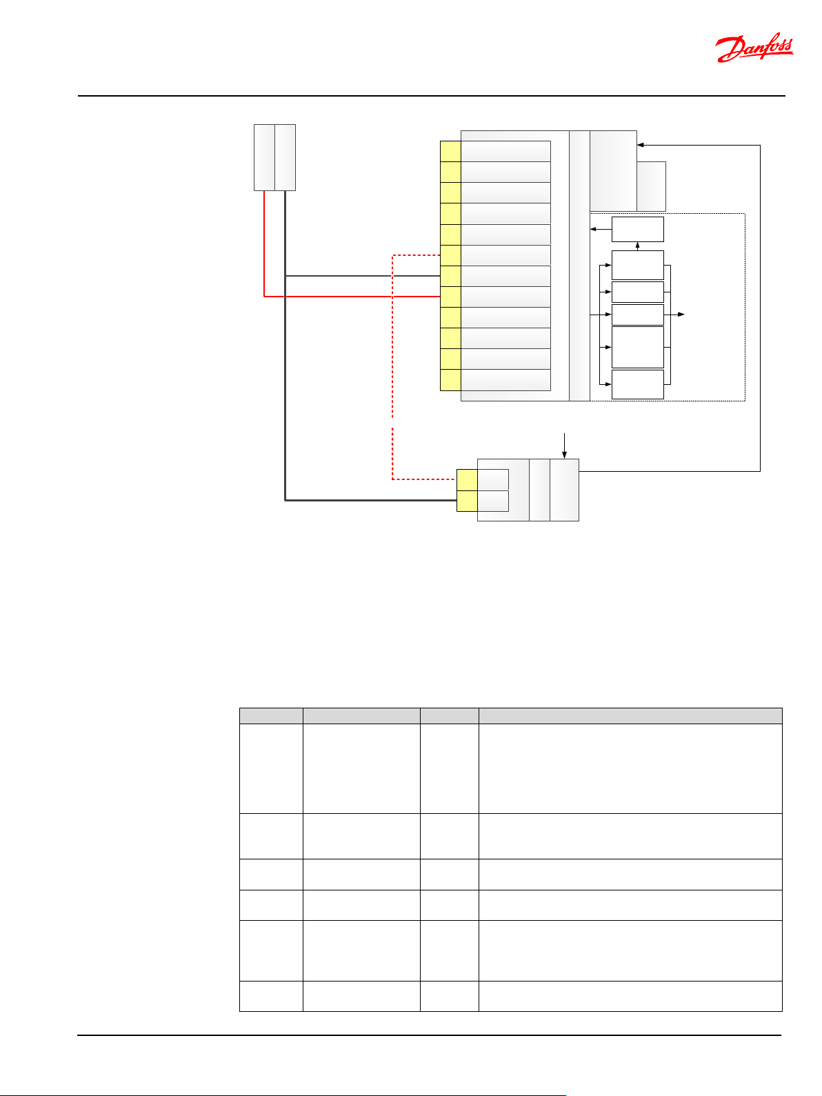
MultiAxis-Steer technical information
System Architecture
Battery (-)
Battery (+)
Additional circuit breakers
Hydraulic pilot pressure
source
Hydraulic pilot pressure
Software
Solenoid Valve
Bridge
EH valve
PVED
-CLS
DT04-
12PA-B016
AD
2
AD
3
Sensor GND
CAN H Safety
CAN L Safety
CutOff out
Battery
(-
)
Battery (+)
CAN L Main
CAN H Main
5
V sensor supply
AD1
1
2
3
4
5
6
7
8
9
10
11
12
Fault
(enter safe state
)
Digital output
current
measurement
Digital output
over
-current
protection
(
hw/
sw
)
Digital output
short
-
circuit
monitoring
Current
monitoring
COV
monitoring
Cut-
off valve
output driver
Cut-off coil
DT
06-2S
Pin1
Pin2
+
-
COV
Address
Name
Unit
Description of parameter
Cut-off valve present.
integrity.
Cut-off valve control mode.
255 = Closed loop current control (default))
Cut-off valve CL pull
current
Cut-off valve pull current (closed-loop current control).
Cut-off valve CL hold
current
Cut-off valve hold current (closed-loop current control).
Cut-off valve monitoring POST time-out. The COV check
Note: Setting P3078 = 0 will disable COV monitoring.
Valve type.
(0 = OSPE or EHi-E (default)
Interface
The COV solenoid valve shall be connected to the monitored PVED-CLS high-side switch output (pin 6)
and battery –(ground). It is recommended to establish the COV solenoid valve ground connection as
close the PVED-CLS ground (pin 7) as possible to avoid voltage drops and current loops.
Configuration for EHi-E valve sub-systems
Cut-off valve related configuration parameters and recommended values, for systems using EHi-E valve
sub-systems can be seen below.
BC321571012557en-000104 © Danfoss | Nov 2019 | 60
P3072 Cut-off valve present BOOL
P3073
P3074
P3076
P3078
P3081 Valve type dec
Figure 30: Cut-off valve architecture for OSPE, EHi-E and EHi-H valve sub-system.
Cut-off valve control
mode
Cut-off valve
monitoring POST
timeout
x10mSec
BOOL
mAmp
mAmp
(0 = not present (EHPS), 225 = present (default)(OSPE,
EHi-E and EHi-H))
Note: For OSPE, EHi-E and EHi-H valve sub-systems,
P3072 shall be 255 to achieve the maximum safety
(0 = Open loop current control,
will fail if started and not succeeded within the set timeout period.
Page 61

MultiAxis-Steer technical information
System Architecture
Cut-off solenoid valve PWM preload. The current build-
H valve sub-systems.
up can be preloaded when the solenoid valve is
P3093
Cut-off valve PWM
pre-load value
powered, this speeds up the time it takes to pull the
%
armature.
P3097 = 100 % is recommended for OSPE, EHi-E and EHi-
Monitoring for EHi-E valve sub-systems
By utilizing the SVB and the EH-valve main spool position sensor, the following monitoring is achieved:
• Full-stroke testing of the COV.
• Full-stroke testing of the cut-off solenoid valve.
The test checks that the COV can enter blocked state. No EH-steering functionality is possible until the
test has passed.
The COV solenoid valve and COV is tested every time the MMI commands the PVED-CLS from on-road
mode into off-road mode. The monitoring function is designed to work in the full operational
temperature range. The test is designed not to fail due to lack of pump pressure and will wait forever
for the initial spool movement. As a consequence, a stuck closed Cut-Off spool will not be detected. In
this case, the operator will notice that EH-Steering is not possible.
Some examples of test execution times, using oil type Tellus 32, are:
• Oil temp -25 °C (6000 cSt) results in test duration: ~6.0 s
• Oil temp -20 °C (4500 cSt) results in test duration: ~3.1 s
• Oil temp -10 °C (1700 cSt) results in test duration: ~1.3 s
• Oil temp 0 °C (761 cSt) results in test duration: ~0.7 s
• Oil temp 20 °C (203 cSt) results in test duration: ~0.6 s
• Oil temp 40 °C (75 cSt) results in test duration: ~0.6 s
Important
• The monitoring technique is based on an intermittent test pulse principle.
• A diagnostic coverage in the range 90-99 % may be claimed, provided that the sub-system is
integrated according to the specification.
EHi-valve monitoring
The PVED-CLS has an integrated EH-valve main spool position sensor (LVDT-sensor) which is used for 1)
closed-loop EH-valve main spool positioning and for 2) EH-valve main spool monitoring.
EH-valve main spool control principle
The main controller calculates a EH-valve main spool set-point every 10ms. The set-point is input to the
Solenoid Valve Bridge (SVB) which pilots the EH-valve main spool towards the calculated spool setpoint. The actual EH-valve main spool position is measured via the LVDT sensor and fed back to the
software for closed-loop spool position control. When the spool position control error is zero the EHvalve main spool is kept at the set-point.
EH-valve main spool monitoring –EHi-E valve sub-systems
The principle of spool monitoring is depicted in
• The EH-valve main spool shall be within the mechanical neutral position threshold (P3086)
• The spool is positioned at or less than the set-point (green dots) and
• The spool is positioned no further than the |set-point + spool monitoring max threshold
• The spool monitoring max threshold range are marked with orange arrows.
A spool monitoring fault is detected when the EH-valve main spool position is in the red enclosed
region for more than ‘Spool out of control’ tolerance time equal to 150 ms (P3363). At power-up, the
initial tolerance time is 1000 ms (P3364). The Spool out of control tolerance time is oil viscosity
dependent and will decrease and settle at P3363 ms as the spool dynamics reflects normal operation
conditions. The tolerance time decline rate is determined by an initial tolerance time constant (P3366)
and the observed spool dynamics measured over a 10 ms interval.
Figure 31. The criterion for safe spool control is:
when the SVB is de-energized.
(P3362)│.
BC321571012557en-000104 © Danfoss | Nov 2019 | 61
Page 62

MultiAxis-Steer technical information
System Architecture
Spoo l
setpoint
Spoo l pos iti on
Safe-state
after 150ms (OSPE)
Safe-state
Normally after 150ms
Address
Name
Unit
Description of parameter
Spool monitoring -
position
position
Spool monitoring -
control' tolerance time
Minimum ‘spool out of control’ tolerance time
Spool monitoring -
time
Initial ‘spool out of control’ tolerance time
Spool monitoring -
decrease rate
‘Spool out-of control’ time constant.
by P3379 and P3378.
Attention
P3362
P3363
P3364
P3366
Figure 31 Spool monitoring
Max difference
between spool setpoint and spool
Min 'spool out of
Max “spool out of
control” tolerance
Confidence time
x10u Meter
x10mSec
x10mSec
dec
Max difference between spool set-point and spool
The effective tolerance time is in the range given
Do not modify the above parameters.
Contact Danfoss PAE for questions to the above parameters.
BC321571012557en-000104 © Danfoss | Nov 2019 | 62
Page 63

MultiAxis-Steer technical information
System Architecture
Attention
Address
Name
Unit
Description of parameter
Temperature severity level
INFO)
Environmental control measures
PCB overheating shut-down
The installation of the PVED-CLS is critical for the machine uptime. In order to respect the absolute
stress ratings of the electronic components, the PVED-CLS must be carefully installed in an area with a
known maximum ambient temperature.
The PCB ambient temperature is measured internally and is a sum of the ambient temperature of the
PVED-CLS installation and the self-heating of the PVED-CLS.
The PVED-CLS must not be installed in areas where the ambient temperature exceeds
85°C.
Contact a Danfoss Product Application Engineer for further information.
For controlling common cause failure, the PVED-CLS features the following functions
• PCB overheating shut-down
• PCB average over-temperature warning
Under normal operation the PVED-CLS must continuously measure the PCB temperature. If the PCB
temperature exceeds 120 °C, the PVED-CLS enters safe state immediately.
For manufacture testing purposes only, it is possible to disable this function by setting the temperature
severity level to INFO. Thereby the PVED-CLS will not to enter safe state if the PCB temperature exceeds
120 °C.
PCB average over-temperature warning
DC power supply
BC321571012557en-000104 © Danfoss | Nov 2019 | 63
P3371
Severity level for temperature
monitoring
BOOL
(0 = Severity level: Critical, 255 = Severity level:
Important
• It is strictly prohibited to set the temperature severity level to other than critical.
• Setting the temperature severity level to other than critical leads to immediate loss of
warranty.
The PVED-CLS maintains a PCB temperature histogram to monitor the average PCB temperature over
the PVED-CLS life-time. A J1939 DM1 Information message will be issue if the average temperature
exceeds 85 °C. The PVED-CLS will continue operation while issuing the info CAN message.
Important
It is recommended that an external ECU is configured to listen the average over-temperature
information. If observed the system integrator should consider revising the PVED-CLS installation
environment.
The temperature histogram can be read out of memory by e.g. the PLUS+1® PVED-CLS service tool.
The PVED-CLS is designed to operate reliably at battery voltages between 11 and 35.5V. Protection
circuitry ensures that the PVED-CLS electronics can withstand the absolute maximum voltage levels.
Circuitry is in place to perform voltage control with safety shut-off to address over-voltage failure
scenarios which could potentially lead to loss of safety functions.
Important
• If the power supply goes below 5.5V, the PVED-CLS will shut down without sending any
warning.
• If the voltage goes below 9V, the PVED-CLS will stay in operation mode but send out an INFO
level DTC.
• Note that below 9V the electro-hydraulic functions of an EHPS, EHi and OSPE may work at a
reduced performance.
• In case the supply voltage exceeds 35.5V, a DTC is issued on the CAN bus, and the PVED-CLS
will enter safe state.
• On detection of internal supply over-voltages, the power to the solenoid valve bridge and the
cut-off solenoid valve will be switched off by discrete circuitry.
Page 64

MultiAxis-Steer technical information
System Architecture
Experience shows that excessively low supply voltage may occur during engine cranking in cold
conditions, depending on the state of battery charge, and/or general state of battery.
Refer to [PVED-CLS Technical Specification] for the absolute maximum electrical steady-state voltage
levels.
See [Diagnostic Trouble Codes] on page 96 for details on error codes.
BC321571012557en-000104 © Danfoss | Nov 2019 | 64
Page 65

MultiAxis-Steer technical information
System set-up
State
LED behavior
Main µC in the bootloader mode
bootloader mode
PVED-CLS is performing the initialization
steering disabled)
PVED-CLS is in the Safe State and information
bus
PVED-CLS is in the off-road steering mode (N-
position or PVED-CLS is in the service mode
The coils supply switch is turned on and the spool
is outside its dead-band
PVED-CLS is in the Safe State, but no
bus-off situation)
PVED-CLS Pinout
Deutsch Connector
1
AD2 7 Power ground (-)
2
AD3 8 Power supply (+)
3
Sensor power ground (-)
9
CAN Low MAIN
4
CAN High SAFETY
10
CAN High MAIN
5
CAN Low SAFETY
11
5V sensor supply (+)
6
Digital output
12
AD1
System set-up
Installation
PVED-CLS Connector interface
LED diagnostic
For a description of the connector interface of PVED-CLS – please refer to [PVED-CLS Technical
Specification].
The PVED-CLS will only be available with connector variant: 12 pin Deutsch DT04-12PA-B016
connector.
The PVED-CLS is equipped with a LED. The LED behavior will inform about the state of the PVED-CLS:
Calibration
Straight heading calibration
System integration and testing
or Main µC detects the Safety µC in the
or is in the on-road mode (electro-hydraulic
about the detected failu r e is available on CAN
Axis operational) and the spool is in its neutral
Blinking between orange and green
Orange
Blinking orange
Green
Blinking gree n
information abou t the detected failure is availabl e
on CAN bus (e.g. the address arbitration has been
lost or the Main µC built-in CAN controller
Red
failed to initialize or is unable to recover from the
This section is pending
As specified in the safety-life cycle; after installation, integration or modification of the PVED-CLS, valve
and other sensors, the system integrator or another representative for the OEM shall validate the
installation, configuration and correct behavior before releasing the vehicle for series production.
System integration testing shall cover the fully integrated system including
• Hydraulic installation
• Mechanical installation including sensor installation
• Electrical installation and cable harness
BC321571012557en-000104 © Danfoss | Nov 2019 | 65
Page 66

MultiAxis-Steer technical information
System set-up
Warning
Attention
•
Vehicle Fault Insertion Testing
Safety validation testing
• Software configuration
• Functional safety
• Interface to other sub-systems
• Systematic safety integrity of the safety channels
The system integration testing shall always be performed before start of
production and after modification of the system.
For further information on validation consult IEC 61508, ISO 13849 or ISO 25119.
The functional safety provided by the PVED-CLS and valve may work differently from vehicle to vehicle
as it may depend on factors such as configuration, vehicle geometry, valve size and cylinder volume.
The system integrator is advised to perform fault insertion testing on the integrated system for failure
modes where the system reaction to a fault cannot be predicted or simulated.
Contact Danfoss Power Solutions PAE for more information.
Validation is the final test of the functional safety before commissioning the system to the end.
This safety validation test activity shall:
• Answer the question if the system is integrated correctly.
• Answer the question if the system is configured as specified.
• Answer the question if the system is working correctly.
• Achieve confidence in that the installation is performed correctly and that the specified
functional safety is working as expected.
Contact Danfoss Power Solutions PAE for more information.
Service part handling and repair instruction
Do not attempt to perform modifications or repair of the PVED-CLS or
valve.
• Do not perform any unauthorized software download or modification of
the PVED-CLS
• If the product is covered by the warranty then it shall be returned to
Danfoss for inspection and root cause analysis
• Repairing a PVED-CLS shall be done by replacing it with a new unit.
• Perform safety validation of the PVED-CLS before commissioning into
the target system/vehicle.
• The replaced PVED-CLS shall be decommissioned by e.g. adequately
marking the part to avoid unintended installation to another vehicle or
modifying the part so re-installation is never possible.
Refer to the [EHi steering valve technical information] for valve repair instructions.
Refer to the [PVED-CLS MultiAxis-Steer firmware release note] for PVED-CLS service part software
operations.
Safety validation steps after replacing a PVED-CLS with a service part
Steps 1-2 may be performed before or after mounting the PVED-CLS to the steering valve.
1. Use the PLUS+1® service tool or read out the Identification data of the PVED-CLS.
2. Compare the following software elements to the customer drawing/specification
a. Bootloader software version
b. Main controller software version
c. Safety controller software version
d. Parameter sector CRCs for the following sectors
BC321571012557en-000104 © Danfoss | Nov 2019 | 66
Page 67

MultiAxis-Steer technical information
System set-up
Service Tool (detailed)
i. SVC (VPS)
ii. Hydraulic Configuration
iii. CAN Wheel Angle Sensor
iv. Analogue Wheel Angle Sensor
v. Peripherals Configuration
vi. Communication Protocol
vii. Internal Monitoring
viii. Vehicle Geometry
ix. N-axis Configuration
x. Auto-calibration
The sector CRCs for each sector shall match the CRCs on the customer drawing/specification.
1. Perform Wheel Angle Sensor and Spool calibration to complete the service part software
configuration.
2. Refer to section System integration and testing on system validation after modification
and repair.
BC321571012557en-000104 © Danfoss | Nov 2019 | 67
Page 68

MultiAxis-Steer technical information
Appendix
Parameter
Address
Format
Description
Sales order number byte 1
P4064
U8
Sales order number (8 digit number)
Sales order number byte 2-7
P4065P4070
Sales order number byte 8
P4071
Sales order number byte 9-14
P4072-4077
Reserved
Identification data item
Format
Size (bytes)
Boot-loader software version
ASCII
39
Boot-loader program date
BCD 3 Application software version
ASCII
39
Application program date
BCD
3
Boot-loader software
version
BOOT_CLS-_M_R385_KWP2000-_11153472_-rrr
Boot-loader program date
13.03.15
Application software version
APP-_CLS-_M_R100_NAXIS---_11153340_-B02
Application program date
05.08.19
Boot-loader software
version
BOOT_CLS-_M_R385_KWP2000-_11153472_-rrr
Boot-loader program date
13.03.15
Application software version
APP-_CLS-_S_R100_NAXIS---_11153341_-B02
Application program date
05.08.19
Appendix
Component identification via CAN bus
The following information identifies the PVED-CLS and valve assembly. The below sections explains the
various methods to perform identification.
Valve assembly barcode label
The valve assembly barcode for the fully assembled valve unit number consists of the order number (8
digit number) and a serial number. The order number specified on the customer drawing, identifying
the final valve assembly (valve, valve controller, software, parameters), is glued onto the valve
assembly (OSP gear set) as well as stored electronically in the PVED-CLS on the following parameter
addresses.
The data can be accessed by uploading the data in boot-loader mode. See [PVED-CLS KWP2000
protocol].
Bootloader and application software identification
The following electronic identification for the embedded software can be retrieved from the PVED-CLS
via the CAN bus.
The boot-load and application software and program date information is stored in flash memory and
generated by Danfoss at compile time for the main and safety controller respectively. The data is
accessible via the KWP2000 Read ECU Identification service. See [PVED-CLS KWP2000 protocol].
Example for main controller:
Sub-string ‘M’ means main controller. Sub-string ‘R198’ means release software version 1.98. Sub-string
‘11153340’ is a Danfoss part number for the main application software. ‘B02’ indicates the build
number.
For the boot-loader software version ‘-rrr’ are reserved characters.
Example for safety controller:
Sub-string ‘S’ means safety controller. Sub-string ‘R100’ means release software version 1.00. Sub-string
‘11153341’ is a Danfoss part number for the safety application software. ‘B02’ indicates the build
number.
For the boot-loader software version ‘-rrr’ are reserved characters.
BC321571012557en-000104 © Danfoss | Nov 2019 | 68
Page 69

MultiAxis-Steer technical information
Appendix
Parameter
Address
Format
Description
Danfoss serial number byte 1
P962
Danfoss serial number byte 2-24
P963-985
Danfoss serial number byte 25
P986
1
2
3 4
5
6
7
8
9
10
11
12
13
14
15
16
17
18
19
20
21
22
23
24
25
1
1 1 0 8 6 8 1 - A 1 2 0 1 1 7 1 3 5 1 3
0 0 0
4
Part no.
Rev
Plant code
Line
Date (yywwd)
Serial no.
PVED-CLS component identification and serial number
The PVED-CLS valve controller can be identified by a serial number which is stored in the PVED-CLS
eeprom memory.
The below example shows how the PVED-CLS serial number is encoded:
The data can be accessed by uploading the data in boot-loader mode by the [PVED-CLS KWP2000
protocol].
PLUS+1 Service tool identification page
The software and hardware can also be uniquely identified via the PLUS+1® service tool page
“Identification” in the Diagnostics group.
U8 PVED-CLS Serial number
Example of the information on the Identification page:
J1939 request PGN for software ID and component ID
The software identification and component identification can be retrieved by a request program group
query for software identification (PGN 65242) and component identification (PGN 65259). The data can
be queried while the PVED-CLS is in operation mode.
Requesting Software ID will return the same data as given in section TBD. Both the boot-loader
software version and application software version is output in one Broadcast Announcement Message.
BC321571012557en-000104 © Danfoss | Nov 2019 | 69
Page 70

MultiAxis-Steer technical information
Appendix
1 2 3 4 5 6 7 8 9
10
11
12
13
14
15
16
17
18
19
20
21
22
23
24
25
26
27
28
* 1 1 1 0
8 6 8 1 * A 1 2 0 1 1 7 1 3 5 1 3 0 0
0
4 *
*
Sector
CRC
CRC
0
Boot Data
0
19
20
BootNodeID,
AppChksum etc. params
NO 0 13 - -
1
Sector CRC Sign Data
20
69
50
Sector CRC Signature Data
NO
20
69
68 - 2
Device Identification
70
149
80
Component ID i.e. Product
Number etc. info
YES
70
102
148
66
3
SVC Params
150
249
100
SVC Parameters
YES
150
210
248
20
4
Control Data
250
459
210
Spool_Max_A_Side,
etc.
YES
250
292
458
26
5
Safety Data
460
529
70
Monitoring related params,
Params etc.
NO
460
527
528
22
6
Protocol Data
530
599
70
Transmit repetition rate and
Timeouts etc. config data
NO
530
565
598
28
7
Diagnostics Data-1
600
765
166
OccCounters etc.
NO
600
752
764 - 8
Diagnostics Data-2
766
849
84
Temperature Histogram
NO
766
835
848 - 9
Calibration Tables
850
961
112
LVDT Table etc
YES
850
931
960
24
10
SD Serial Number
962
999
38
SD serial number
YES
962
996
998
66
11
Diagnostics Data-3
1000
1691
692
Extended ErrorFIFO
NO
1000
1690 - -
12
Diagnostics Data-4
1692
1741
50
Min, Max task timings
NO
1692
1740 - -
Error code occurance last
14
Reserved
2342
3071
730
Reserved for Platform
NO
2342
3071 - -
15
Hydraulic Config
3072
3121
50
Hydraulic Config
YES
3072
3097
3120
40
16
Reserved
3122
3161
40
Reserved
NO
3122
3161 - -
17
Valve Calibration Data
3162
3184
23
Valve Calibration Data
YES
3162
3171
3183
44
18
CAN WAS Calibration
Data
3185
3204
20
CAN WAS Calibration Data
YES
3185
3196
3203
46
19
Analog Sensor
Calibration Data
3205
3236
32
Analog Sensor Calibration
Data
YES
3205
3226
3235
48
20
Peripherals Config
3237
3286
50
Peripherals Config
YES
3237
3245
3285
50
21
N-Axis Protocol Data
3287
3350
64
N-Axis Protocol Data
YES
3287
3325
3349
52
22
Internal Monitoring
3351
3420
70
Internal monitoring
YES
3351
3383
3419
54
23
Reserved
3451
3770
320
Reserved
NO
3421
3770 - -
24
Production/Calibration
Flag
3771
3790
20
Production/Calibration Flag
NO
3771
3776
3789 - 25
Auto Calibration
Config
3791
3863
73
Auto Calibration Config
YES
3791
3851
3862
64
26
N-Axis
3864
4063
200
N-Axis
YES
3864
3926
4062
66
27
PLM metadata
4064
4209
146
Teamcenter engineering
document numbers
NO
4064
4189
4208 - 28
OEM Data
4210
4311
102
OEM data
NO
4210
4311
-
Requesting Component ID will return the same data as given in section TBD-
Example of data broadcasted by Component Identification BAM:
EEPROM parameters
EEPROM layout
# Sectors
Refer to [PVED-CLS MultiAxis-Steer communication protocol] for details.
The full parameter set is divided into sectors which are described below.
Start
Addr
End
Addr
Size
(bytes)
Description
BootSWVersion,
Code + Device Serial
DBC_A_Side, Scaling,
Limiting, Road-Flow Curves
Safety Controller Config
CRC
protection
calculation
Start Addr
calculation
End Addr
CRC
Addr
SIGNATURE
Addr
13 Diagnostics Data-5 1742 2341 600
BC321571012557en-000104 © Danfoss | Nov 2019 | 70
and latest time stamps NO 1742 2298 - -
Page 71

MultiAxis-Steer technical information
Appendix
29
Reserved
4312
4391
80
Reserved
NO
4312
4391
-
• Modifying behavior includes changing or disabling a safety function or a
Step
Description
Response/result
1
Enter boot-loader mode
PVED-CLS de-energizes all outputs (safe
configuration memory.
2
User identification
The user identifies him/her-self and request
state on the subsequent power-up.
3
Upload data
controller in a diverse data format
The PVED-CLS returns all parameter values to
step 4 and 5.
4
Data modification
and characters)
sector CRC is stored in service tool memory.
5
Download data
When downloading a new sector to the main
the PVED-CLS.
6
Upload data
characters
write procedure in step 5.
7
Data validation
The user inspects that the data is correctly
sector are valid.
8
User approval signature
The PSAC for the modified sector is
memory.
Safety parameterization
Safety parameterization procedure
Note: Sectors with gray background ( ) are for internal purpose only and are not described in the manual
Parameterization or configuration is the process of modifying software parameters in EEPROM which
can modify the behavior of the safety device.
Warning
monitoring function behavior or performance.
• Any parameterization of the PVED-CLS shall follow the be devised safety
parameterization procedure.
The PVED-CLS support protocol services which enable the design of safe parameterization covering the
channel; the service tool user, the service tool hardware and software, the communication channel and
the PVED-CLS eeprom memory.
Set the PVED-CLS in boot-loader mode
Enter the access level (Manufacturer, OEM or
dealer) and the Parameter Sector Access Code
(PSAC)
condition) and enables access to
access rights to the sectors subject for
modification. Failing to set the PSAC or
unauthorized modification attempts will be
detected and bring the PVED-CLS into the safe
Upload the data for the sector which is subject
for modification. Request uploading data in
the diverse data format. Decode and display
the data for both the main and safety
Modify one or more parameters in the sector
and calculate the sector CRC value. Input
values are entered as strings values (numbers
Download the modified sector and the
associated sector CRC from service tool
memory to both the main and safety
controller memory
Upload the data for the sector which is subject
for modification. Request uploading in diverse
data format. Decode and display the data for
both the main and safety controller as ascii
The user shall inspect all parameter values in
the sector
The user approves the data in the sector by
calculating the signature CRC. The signature
the service tool as bit-wise inverted data. The
diverse data enforces realization of a readback and display method in the service tool
which is diverse from the write procedure in
The data is encoded from string-tohexadecimal values. The modified sector and
and safety controller, the previous signature
CRC becomes invalid. The PVED-CLS will be
locked in the safe state until a correct
signature CRC is created and downloaded to
The PVED-CLS transmits all parameter values
as bit-wise inverted data. The diverse data
format enables the realization of a read-back
and display method which is diverse from the
modified and that the other parameters in the
downloaded to the PVED-CLS configuration
BC321571012557en-000104 © Danfoss | Nov 2019 | 71
Page 72

MultiAxis-Steer technical information
Appendix
CRC depends on the sector CRC and the
entered PSAC
9
Reset
changes to take effect
The user shall validate the changes.
Important
Contact Danfoss Power Solutions PAE for information on the OEM and Dealer PSAC.
Reset or power-cycle the device for the
Safe parameterization is complete.
• The service tool user closes the safety loop during parameterization i.e. a skilled user
approves the parameter settings.
• Details on safe parameterization can be found in the PVED-CLS KWP2000 protocol and PVED-
CLS Parameter Description.
• The PLUS+1® service tool for the PVED-CLS uses the safe parameterization procedure.
• Unauthorized changes will lead to a permanent safe state condition until the correct
parameters are approved.
BC321571012557en-000104 © Danfoss | Nov 2019 | 72
Page 73

MultiAxis-Steer technical information
Appendix
Ad
dr
Type Uni
t
Defau
lt
Checksum of Application that Boot-Loader
So, this value shall NOT be modified by user at all.
Node-ID used by Boot-loader. Default value is
Node-ID is between {0x20 - 0x2F}.
This EE location is used by the application to
ALWAYS Use a Default value of 0x00.
Default = 250K
This Baud rate value is configured by application
ALWAYS Use a Default value of 0x00.
This EE location is configured by the bootloader
ALWAYS Use a Default value of 0x00.
This EE location indicate SafeUC image is
compatible with MainUC.
SW_RESET_CONTED_TOOL_NO
KWP_DLC_VALIDATION_STATU
S
P14
P19
Boot Data
P0
Name
BL_APP_DOWNLOAD_CHECKS
UM
U8 Hex
Description MIN MAX
calculates and stores after programming the
device with valid application. Boot-loader uses
this value at every boot-up for verifying whether
a valid application is present in the device or not.
00
P1 Reserved / Unused U8 Hex Reserved for use in Future.
00
P2 Network Node ID U8 Hex Reserved for use in Future. 0 255 00
P3 BOOT_NODE_ID U8 Hex
0x20. The actual valid range for this KWP2000
0 255 20
indicate which 'Diagnostic Session' is to be
P4 APP_TO_BOOT_FLG U8 Hex
started in 'Boot-loader mode'; after 'Software-
0 255 00
Reset' is performed from Application.
Initial Baud rate for Bootloader . Can be
configured as
P5 BAUD_RATE U16 dec
125K
250K
125 1000 250
1000K
when START DIAGNO with baud rate change is
P6 NEW_BAUD_RATE_FRM_APP U16 dec
Rxd in application. It get reseted in Bootloader.
0 1000 0
to indicate jump to application is due to STOP
P7 BOOT_TO_APP_FLG U8 Hex
DIAGNO msg and application has to send
0 255 00
positive response for the same msg.
SAF_UC_IN_SYNC_WITH_MAIN
P8
_UC
SW_RESET_CONNECTED_TOOL
P9
_INFO
P10
DE_ID
P11
-
U N U S E D
BC321571012557en-000104 © Danfoss | Nov 2019 | 73
compatible with MainUC.
This parameter is reset by bootloader while
flashing new application.
Application will set the values as follow
U8 Hex
0x02 : Both Application and Bootloader
0 3 00
compatible with MainUC.
0x01 : Bootloader is compatible but Application
is not compatible with MainUC.
0x00 : Both Application and Bootloader not
Connected service tool information
0: Normal mode standard message tool
U8 Hex
1: Mixed mode tool
0 255 FF
2: Normal mode extended message tool
0xFF: Invalid tool (default)
U8 Hex Connected KWP tool Node ID. 0 255 00
U8 Hex 0: Optimized DLC 255: Frame Padding. 0 255 00
Important Parameters with gray background ( ) are internal and must not to be changed!
0
Page 74

MultiAxis-Steer technical information
Appendix
P30-
P39
P42-
P43
Sector CRC Sign Data
Addr Name Type Unit Description MIN MAX Default
This EE location is reserved to store the sector
SVC_PARAM_SECTOR_CRC_
P20
SIGN
SAFETY_DATA_SECTOR_CRC
P22
_SIGN
CALIB_TABLE_SECTOR_CRC_
P24
SIGN
CONTROL_DATA_SECTOR_C
P26
RC_SIGN
U16 dec
U16 dec
U16 dec
U16 dec
signature CRC.
The signature CRC shall be calculated by the
configuration tool. A correct CRC value is
equivalent to approved parameter changes.
This EE location is reserved to store the sector
signature CRC.
The signature CRC shall be calculated by the
configuration tool. A correct CRC value is
equivalent to approved parameter changes.
This EE location is reserved to store the sector
signature CRC.
The signature CRC shall be calculated by the
configuration tool. A correct CRC value is
equivalent to approved parameter changes.
This EE location is reserved to store the sector
signature CRC.
The signature CRC shall be calculated by the
configuration tool. A correct CRC value is
equivalent to approved parameter changes.
0 65535 2920
0 65535 47848
0 65535 13034
0 65535 64557
This EE location is reserved to store the sector
PROTOCOL_DATA_SECTOR_
P28
CRC_SIGN
U16 dec
signature CRC.
The signature CRC shall be calculated by the
configuration tool. A correct CRC value is
0 65535 44206
equivalent to approved parameter changes.
Reserved / Unused U8 dec - 0 255 00
This EE location is reserved to store the sector
HYDRA_CONFIG_SECTOR_C
P40
RC_SIGN
U16 dec
signature CRC.
The signature CRC shall be calculated by the
configuration tool. A correct CRC value is
0 65535 7759
equivalent to approved parameter changes.
Reserved / Unused U8 dec - 0 255 0
This EE location is reserved to store the sector
VALVE_CALIB_DATA_SECTO
P44
R_CRC_SIGN
U16 dec
signature CRC.
The signature CRC shall be calculated by the
configuration tool. A correct CRC value is
0 65535 15743
equivalent to approved parameter changes.
This EE location is reserved to store the sector
CAN_WAS_DATA_SECTOR_C
P46
RC_SIGN
U16 dec
signature CRC.
The signature CRC shall be calculated by the
configuration tool. A correct CRC value is
0 65535 35804
equivalent to approved parameter changes.
BC321571012557en-000104 © Danfoss | Nov 2019 | 74
Page 75

MultiAxis-Steer technical information
Appendix
Cut-off Valve
255 (PRESENT)
Cut-off Valve
control)
Current required
valve
Current required
in ON state
Cut Off Valve
safety check
Addr Name Type Unit Description MIN MAX Default
This EE location is reserved to store the sector
AN_SEN_DATA_SECTOR_CR
P48
C_SIGN
U16 dec
signature CRC.
The signature CRC shall be calculated by the
configuration tool. A correct CRC value is
0 65535 31598
equivalent to approved parameter changes.
This EE location is reserved to store the sector
PERIPH_CONFIG_SECTOR_C
P50
RC_SIGN
U16 dec
signature CRC.
The signature CRC shall be calculated by the
configuration tool. A correct CRC value is
0 65535 43077
equivalent to approved parameter changes.
This EE location is reserved to store the sector
NAXIS_PRTCL_DATA_SEC_C
P52
RC_SIGN
U16 dec
signature CRC.
The signature CRC shall be calculated by the
configuration tool. A correct CRC value is
0 65535 23939
equivalent to approved parameter changes.
This EE location is reserved to store the sector
INTRNL_MONITOR_SECTOR_
P54
CRC_SIGN
U16 dec
signature CRC.
The signature CRC shall be calculated by the
configuration tool. A correct CRC value is
0 65535 22773
equivalent to approved parameter changes.
Hydraulic Config
Addr Name Type Unit Description MIN MAX Default
Present/Not
P3072 Cut-off valve present U8 BOOL
Present
Valid Values: 0
0 255 255
(NOT PRESENT);
control mode
Close loop Control
P3073 Cut-off valve control mode U8 BOOL
or ON-OFF control
Valid Values: 0
0 255 255
(ON-OFF control);
255 (Closed loop
P3074 Cut-off valve CL pull current U16 mAmp
P3076 Cut-off valve CL hold current U16 mAmp
to activate Cut-off
to maintain Cut-off
100 2000 1100
100 2000 500
Activation
TimeOut for COV
Monitoring feature
P3078 Cut-off valve monitoring POST timeout U16 x10mSec
while entering Off
Road state.
0 1000 900
INFO: Setting this
parameter to 0 will
bypass off-road
BC321571012557en-000104 © Danfoss | Nov 2019 | 75
Page 76

MultiAxis-Steer technical information
Appendix
Changes the
EHPS)
PVED-CLS is
(EHPS); 2 (EHi-H)
Cylinder stroke
stroke value
EH valve size,
per minute
LVDT Offset
(ENABLE)
10 um
Dec)
Absolute value of
threshold range
Spool left most
sector CRC
Spool right most
sector CRC
Spool open loop
sector CRC
Cut-off valve PWM
pre-load value
Addr Name Type Unit Description MIN MAX Default
direction of the
requested flow
P3080 Invert flow direction U8 BOOL
Valid Values: 0
(NO, DEFAULT
0 255 0
OSPE/EHi); 255
(YES, DEFAULT
attached to which
P3081 Valve type U8 dec
type of valve?
Valid Values: 0
0 2 0
(OSPE or EHi-E); 1
volume.
Acceptable values:
100-10000.
P3082 Cylinder stroke volume U16 ccm
Note -> Writing
100 65535 500
65535 will force to
use automatic
adjusted cylinder
P3084 Valve capacity U8 lpm
P3085 LVDT offset compensation Enable/Disable U8 BOOL
P3086 Absolute Spool neutral threshold range U8
P3087 Max Spool pos left copy SIGNED16
P3089 Max Spool pos right copy SIGNED16
P3091 Offset dead-band OL copy SIGNED16
(signed
x10u
Meter
x10u
Meter
x10u
Meter
defined in liters
compensation
Valid Values: 0
(DISABLE); 255
Spool neutral
position copied
from spool autocalibration before
the internal
calculation of the
position copied
from spool autocalibration before
the internal
calculation of the
dead-band offset
copied from spool
auto-calibration
before the internal
calculation of the
5 120 20
0 255 255
0 200 25
-1000 0 0
0 1000 0
0 150 0
P3093 Cut-off valve PWM pre-load value U8 %
BC321571012557en-000104 © Danfoss | Nov 2019 | 76
0 100 100
Page 77

MultiAxis-Steer technical information
Appendix
This is the timeout
is disabled
This is the timeout
triggered.
P3098-
P3119
This EE location is
by user at all.
Addr Name Type Unit Description MIN MAX Default
within which the
wheels must get
aligned straight
before going from
P3094
Timeout within which the wheels must get
aligned straight before going from off road to
OnRoad due to road switch position
U16 x10msec
off road to OnRoad
state due to road
switch position.
0 6500 0
After the timeout
the Safestate will
be triggered. If set
to 0 self alignment
within which the
wheels must get
aligned straight
before entering in
Pre-Safe state or
before entering on
road state due to
100 6500 500
P3096
Timeout within which the wheels must get
aligned straight before in Pre-Safe state or in on
road state
U16 x10msec
VSP. After the
timeout the
Safestate will be
UNUSED 0
P3120 HYDRA_CONFIG_SECTOR_CRC U16 dec
reserved to store
CRC
Application
calculates sector
CRC if new .eep file
is downloded.
Application
verifies the sector
CRC value at every
boot-up, to check
the EEPROM sector
data is valid or not.
This value shall
NOT be modified
0 65535 29767
BC321571012557en-000104 © Danfoss | Nov 2019 | 77
Page 78

MultiAxis-Steer technical information
Appendix
Spool Close Loop left deadband edge
Spool Close Loop right deadband edge
Spool Open Loop dead-band
offset
P3172-
P3182
This EE location is reserved to
modified by user at all.
Automatic adjusted maximum
calibration
Automatic adjusted maximum
calibration
P3197-
P3202
This EE location is reserved to store
by user at all.
Valve Calibration Data
Addr Name Type Unit Description MIN MAX Default
P3162 Max spool position, left SIGNED16 x10u Meter Spool left most position -1000 -300 -420
P3164 Max spool position, right SIGNED16 x10u Meter Spool right most position 300 1000 420
P3166 Closed loop dead-band edge, left SIGNED16 x10u Meter
P3168 Closed loop dead-band edge, right SIGNED16 x10u Meter
P3170 Open loop dead-band edge offset SIGNED16 x10u Meter
UNUSED
-300 0 -105
0 300 105
0 150 25
store CRC
Application calculates sector
CRC if new .eep file is
downloaded.
P3183 VALVE_CALIB_DATA_SECTOR_CRC U16 dec
Application verifies the
sector CRC value at every
0 65535 63796
boot-up, to check the
EEPROM sector data is valid
or not.
This value shall NOT be
CAN WAS Calibration Data
Addr Name Type Unit Description MIN MAX Default
P3185 WAS max left position (CAN) U16 mVolts
P3187 WAS max right position (CAN) U16 mVolts
P3189 WAS neutral position (CAN) U16 mVolts
Wheel angle sensor voltage output
for leftmost position over CAN
Wheel angle sensor voltage output
for rightmost position over CAN
Wheel angle sensor voltage output
for neutral position over CAN
0 5000 500
0 5000 4500
0 5000 2500
0
P3191
P3193
P3195
Automatically adjusted cylinder stroke
volume (CAN WAS)
Automatically adjusted maximum
steer angle to left side (CAN WAS)
Automatically adjusted maximum
steer angle to right side (CAN WAS)
UNUSED
P3203 CAN_WAS_DATA_SECTOR_CRC U16 dec
BC321571012557en-000104 © Danfoss | Nov 2019 | 78
U16 ccm
U16 Deg
U16 Deg
Automatic adjusted cylinder stroke
volume, for using CAN WAS, found
during WAS auto-calibration
100 65535 65535
steer angle to left side, for using
CAN WAS, found during WAS auto-
steer angle to right side, for using
CAN WAS, found during WAS auto-
0 65535 65535
0 65535 65535
CRC
Application calculates sector CRC if
new .eep file is downloaded.
Application verifies the sector CRC
value at every boot-up, to check
0 65535 41488
the EEPROM sector data is valid or
not.
This value shall NOT be modified
0
Page 79

MultiAxis-Steer technical information
Appendix
Primary analogue sensor neutral
position
Primary analogue sensor voltage
output for neutral position
5V sensor supply for primary
calibration
Measured Supply voltage during
sensor
5V sensor supply for redundant
calibration
Measured Supply voltage during
sensor
Automatic adjusted cylinder stroke
during WAS auto-calibration
Automatic adjusted maximum steer
calibration
Automatic adjusted maximum steer
calibration
P3227-
P3234
This EE location is reserved to store CRC
user at all.
Specifies whether the road switch is or
The max. current allowed to be
valve connection test.
Analog Sensor Calibration Data
Addr Name Type Unit Description MIN MAX Default
P3205
P3207
Primary analogue sensor max left
position
Primary analogue sensor max
right position
U16 mVolts
U16 mVolts
Primary analogue sensor voltage
output for leftmost position
Primary analogue sensor voltage
output for rightmost position
0 6000 500
0 6000 4500
P3209
P3211
P3213
P3215
P3217
P3219
P3221
P3223
P3225
Redundant analogue sensor max
left position
Redundant analogue sensor max
right position
Redundant analogue sensor
neutral position
analogue sensor during
analogue sensor during
Automatically adjusted cylinder
stroke volume (analogue WAS)
Automatically adjusted maximum
steer angle to left side (analogue
WAS)
Automatically adjusted maximum
steer angle to right side
(analogue WAS)
UNUSED
U16 mVolts
U16 mVolts
U16 mVolts
U16 mVolts
U16 mVolts
U16 mVolts
U16 ccm
U16 Deg
U16 Deg
Redundant analogue sensor voltage
output for leftmost position
Redundant analogue sensor voltage
output for rightmost position
Redundant analogue sensor voltage
output for neutral position
calibration of the primary analogue
calibration of the redundant analogue
volume, for using analogue WAS, found
angle to left side, for using analogue
WAS, found during WAS auto-
angle to right side, for using analogue
WAS, found during WAS auto-
0 6000 2500
0 6000 500
0 6000 4500
0 6000 2500
4650 5350 5000
4650 5350 5000
100 65535 65535
0 65535 65535
0 65535 65535
0
P3235 AN_SEN_DATA_SECTOR_CRC U16 dec
Peripherals Config
Addr Name Type Unit Description MIN MAX Default
P3237
Road switch present (connected
to AD3)
P3238 Max COV connection test current U8 mAmp
P3239 WAS interface U8 dec
BC321571012557en-000104 © Danfoss | Nov 2019 | 79
U8 BOOL
Application calculates sector CRC if new
.eep file is downloded.
Application verifies the sector CRC
value at every boot-up, to check the
EEPROM sector data is valid or not.
This value shall NOT be modified by
is no present, i.e. connected to the
analogue input AD3
Valid Values: 0 (NOT PRESENT); 255
(PRESENT)
observed during the cut-off solenoid
Wheel Angle Sensor Interface Type
Valid Values: 0 (ANALOGUE); 1 (CAN);
0 65535 44044
0 255 255
10 255 100
0 1 0
Page 80

MultiAxis-Steer technical information
Appendix
Redundant Wheel Angle Sensor
(PRESENT)
Supply voltage compensation
Valid Values: 0 (DISABLE); 255 (ENABLE)
Supply voltage compensation
Valid Values: 0 (DISABLE); 255 (ENABLE)
Sensor Supply Test. Disable/enable the
set to 0) all time
5V sensor, AD1 and AD2 filter cut-off
Resolution: 1 dHz = 0.1 Hz
P3246-
P3284
This EE location is reserved to store CRC
user at all.
Vehicle speed sensor
two messages
Wheel Angle Sensor
two messages
N-Axis master message monitoring - max
time difference between two messages
N-Axis previous node's master message
two messages
Previous node's master
timeout
Default transmission rate
Messages
Default transmission rate
of the Status Message 1
Default transmission rate
of the Status Message 2
Default transmission rate
of the Status Message 3
Addr Name Type Unit Description MIN MAX Default
P3240 Redundant WAS present U8 BOOL
P3241
P3242
Voltage compensation for Primary
analogue sensor
Voltage compensation for
Redundant analogue sensor
U8 BOOL
U8 BOOL
Generation of 5V sensor supply
P3243
voltage (Deutsch connector pin
U8 dec
11)
P3244
AD low pass filter cut-off
frequency
U8 dHz
Present/Not Present
Valid Values: 0 (NOT PRESENT); 255
Enable/Disable for processing primary
Analogue sensor signal
Enable/Disable for processing
redundant analogue sensor signal
internal 5V supply on the PVED-CLS’ pin
11.
Valid Values: 0 (Enable); 1 (Disable)
Note: Should be kept at Enable (P3248
frequency
0 255 255
0 255 255
0 255 255
0 1 0
5 200 100
P3245 Total Number of n-Axis nodes U8 dec Total Number of N-Axis nodes 1 4 1
UNUSED
Application calculates sector CRC if new
.eep file is downloded.
P3285 PERIPH_CONFIG_SECTOR_CRC U16 dec
Application verifies the sector CRC
value at every boot-up, to check the
0 65535 34022
EEPROM sector data is valid or not.
This value shall NOT be modified by
0
N-Axis Protocol Data
Addr Name Type Unit Description MIN MAX Default
P3287
P3288
Vehicle speed sensor message monitoring Max time difference between two messages
Wheel angle sensor message monitoring Max time difference between two messages
P3289
P3290
P3291
monitoring - max time difference between
Transmission rate - Operation Status
Messages
P3292 Transmission rate - Status message 1 U8 x10mSec
P3293 Transmission rate - Status message 2 U8 x10mSec
P3294 Transmission rate - Status message 3 U8 x10mSec
BC321571012557en-000104 © Danfoss | Nov 2019 | 80
U8 x10msec
U8 x10mSec
message monitoring - max
time difference between
message monitoring - Max
time difference between
10 255 15
2 255 8
U8 x10mSec Master message timeout 10 255 10
U8 x10mSec
U8 x10mSec
wheel angle limit message
of the Operation Status
10 255 10
1 254 10
0 255 0
0 255 0
0 255 0
Page 81

MultiAxis-Steer technical information
Appendix
Default transmission rate
of the Status Message 4
Default transmission rate
of the Status Message 5
Default transmission rate
of the Status Message 6
Default transmission rate
of the Status Message 7
Default transmission rate
of the Status Message 8
Default transmission rate
of the Status Message 9
Default transmission rate
message
Default transmission rate
of master message
PGN offset to Operation
Status messages
PGN offset to Status
message 1
PGN offset to Status
message 2
PGN offset to Status
message 3
PGN offset to Status
message 4
PGN offset to Status
message 5
PGN offset to Status
message 6
PGN offset to Status
message 7
PGN offset to Status
message 8
PGN offset of status
message 9
PGN offset to Vehicle
speed message
PGN offset to Wheel Angle
Sensor messages
PGN offset of N-Axis master wheel angle
limit message
PGN offset of master wheel
angle limit message
PGN offset of master
message
PGN offset to MMI
format
Source address of N-Axis'
than 1
J1939 Source Address of
the vehicle speed sensor
Addr Name Type Unit Description MIN MAX Default
P3295 Transmission rate - Status message 4 U8 x10mSec
P3296 Transmission rate - Status message 5 U8 x10mSec
P3297 Transmission rate - Status message 6 U8 x10mSec
P3298 Transmission rate - Status message 7 U8 x10mSec
P3299 Transmission rate - Status message 8 U8 x10mSec
P3300 Transmission rate - Status message 9 U8 x10mSec
P3301
Transmission rate - N-Axis master wheel
angle limit message
U8 x10mSec
P3302 Transmission rate - N-Axis master message U8 x10mSec
P3303 PGN offset to operation status messages U8 dec
P3304 PGN offset to status message 1 U8 dec
P3305 PGN offset to status message 2 U8 dec
P3306 PGN offset to status message 3 U8 dec
P3307 PGN offset to status message 4 U8 dec
of master wheel angle limit
0 255 0
0 255 0
0 255 0
0 255 0
0 255 0
0 255 0
0 255 0
0 255 1
0 255 32
0 255 33
0 255 34
0 255 35
0 255 36
P3308 PGN offset to status message 5 U8 dec
P3309 PGN offset to status message 6 U8 dec
P3310 PGN offset to Status message 7 U8 dec
P3311 PGN offset to Status message 8 U8 dec
P3312 PGN offset to Status message 9 U8 dec
P3313 PGN offset to vehicle speed sensor message U8 dec
P3314 PGN offset to wheel angle sensor messages U8 dec
P3315
U8 x10mSec
P3316 PGN offset of N-Axis master message U8 dec
P3317 PGN offset to MMI message U8 dec
message , when using
Proprietary B message
0 255 37
0 255 38
0 255 39
0 255 40
0 255 41
0 255 64
0 255 18
0 255 42
0 255 44
0 255 66
P3318 N-Axis Master Source Address U8 dec Source address of master 0 253 19
previous node. This value
P3319 N-Axis Previous Node Source Address U8 dec
is needed to be set in case
0 255 0
number of slaves is grater
P3320 Vehicle speed sensor source address U8 dec
BC321571012557en-000104 © Danfoss | Nov 2019 | 81
0 253 251
Page 82

MultiAxis-Steer technical information
Appendix
J1939 Source Address of
the MMI
J1939 Source Address of
the PVED
J1939 Source Address of
the wheel angle sensor
Function instance field in
Address calim message
CAN message priority of
3)
P3326-
P3348
This EE location is reserved
modified by user at all.
Typ
e
Maximum allowable time for which wheel
be out of specified value
Channel cross-check
divergence
Max allowable wheel angle reading
micro-controllers
Maximum allowable time for spool
be out of specified value
Channel cross-check
Max allowable flow command difference
Maximum allowable time for which
to be out of specified value
Channel cross-check
speed divergence
Max allowable vehicle speed reading
micro-controllers
Maximum allowable time for which MMI
different
Addr Name Type Unit Description MIN MAX Default
P3321 MMI source address U8 dec
P3322 PVED-CLS source address U8 dec
P3323 Wheel angle sensor source address U8 dec
P3324 PVED-CLS address claim - Function instance U8 dec
P3325
CAN message priority of operational status
message
UNUSED
U8 BOOL
P3349 NAXIS_PRTCL_DATA_SEC_CRC U16 dec
operational status
message
Valid Values:
0 (CAN message priority 6)
255 ((CAN message priority
to store CRC
Application calculates
sector CRC if new .eep file
is downloded.
Application verifies the
sector CRC value at every
boot-up, to check the
EEPROM sector data is
valid or not.
This value shall NOT be
0 253 252
0 253 20
0 253 250
0 32 0
0 255 0
0
0 65535 45750
Internal Monitoring
Addr Name
P3351
P3352
P3354
P3355
P3357
P3358
P3359
Channel cross-check
monitoring - Max wheel angle
divergence time
monitoring - Max wheel angle
Channel cross-check
monitoring - Max calc flow
command divergence time
monitoring - Max calc flow
command divergence
Channel cross-check
monitoring - Max vehicle
speed divergence time
monitoring - Max vehicle
Channel cross-check
monitoring - Max MMI
command divergence time
Unit Description MIN MAX Default
U8 x10msec
U16 IR
U8 x10msec
U16 IR
angle readings between MAIN and
SAFETY micro-controllers are allowed to
difference between MAIN and SAFETY
position set-point between MAIN and
SAFETY micro-controllers are allowed to
in IR between MAIN and SAFETY micro-
0 255 10
0 2000 100
0 255 10
0 2000 100
controllers
U8 x10msec
U8 kmph
U8 x10msec
vehicle speed readings between MAIN
and SAFETY micro-controllers are allowed
difference between MAIN and SAFETY
Flag readings between MAIN and SAFETY
micro-controllers are allowed to be
0 255 10
0 100 5
0 255 10
BC321571012557en-000104 © Danfoss | Nov 2019 | 82
Page 83

MultiAxis-Steer technical information
Appendix
Typ
e
Channel cross-check
sensor divergence (internal)
Max allowed difference between
primary and redundant analogue sensors
Spool monitoring - Max
point and spool position
Max allowed difference between Spool
for Spool monitoring algorithm
Spool monitoring - Min 'spool
out of control' tolerance time
Minimum timeout value used by spool
monitoring algorithm
Spool monitoring - Confidence
time decrease rate
6000
0
Timeout value for Safe ON-ROAD switch
Resolution: 1 x10mSec = 10ms
The analogue sensor output conversions
[IR])
Severity Level for temperature monitoring
Channel cross-check
volume difference
Channel cross-check
difference
Channel cross-check
time
Channel cross-check
time
Channel cross-check
difference time
Addr Name
P3360
P3362
monitoring - Max analogue
difference between spool set-
P3363
P3364
Spool monitoring - Max “spool
out of control” tolerance time
P3366
Channel cross-check
P3368
monitoring - Max road switch
position divergence time
P3369
Scaled Analogue sensor limit
offset
Unit Description MIN MAX Default
U16 IR
x10u
U8
Meter
U8 x10mSec
U16 x10mSec
analogue sensors values measured by
set-point and actual spool position used
Maximum timeout value used by spool
monitoring algorithm
0 2000 50
0 200 80
1 75 15
100 400 100
U16 dec Spool Monitoring time constant 0
U8 x10mSec
position, cross check between MAIN- and
SAFETY-controller.
0 255 10
to internal resolution [IR] based on the
calibration parameters is clamped to
±1000, but internally it is checked that the
U16 IR
un-clamped analogue sensor signal does
0 1000 50
not exceed the range:
(-1000 – P3384 [IR]) < “un-clamped
analogue sensor signal” <(1000 + P3384
8000
P3371
P3372
P3374
P3376
P3377
P3378
Severity level for temperature
monitoring
Wheel angle limit offset (CAN
WAS)
monitoring - Max WAS autocalibrated cylinder stroke
monitoring - Max WAS autocalibrated wheel angle
monitoring - Max N-axis'
virtual axis angle difference
monitoring - Max N-axis'
virtual axis position difference
P3379
monitoring - Max N-axis'
master wheel angle limit
U8 BOOL
U16 IR
U16 ccm
U8 deg
U8 x10msec
U8 x10msec
U8 x10msec
Valid Values: 0 (Severity level: Critical)
255 (Severity level: INFO)
The CAN Wheel angle sensor output
conversions to internal resolution [IR] is
limited to ±1000 IR, based on the
calibration parameters.
But internally it is checked that the unclamped CAN Wheel angle sensor signal
does not exceeds the range: (-1000 –
P3390 [IR]) < “un-clamped analogue
sensor signal” <(1000 + P3390 [IR])
Maximum WAS Auto-calibrated Cylinder
Stroke Volume Difference
Maximum WAS Auto-calibrated wheel
angle Difference
Max time allowed for N-Axis' Virtual Axis
Angle difference
Max time allowed for N-Axis' Virtual Axis
Position difference
Max time allowed for N-Axis' calculated
(for n=1) or received (for n>1) master
wheel angle limit difference
0 255 0
0 1000 50
1000
1
0
50
1 89 3
10 255 10
10 255 10
10 255 10
BC321571012557en-000104 © Danfoss | Nov 2019 | 83
Page 84

MultiAxis-Steer technical information
Appendix
Typ
e
Channel cross-check
time
Channel cross-check
difference
Channel cross-check
Channel cross-check
demand request difference
P3384
P3418
This EE location is reserved to store CRC
at all.
Calibration counter - Spool
calibration
Bit inverted value for "Calibration
counter - Spool calibration"
Bit inverted value for Spool deadband Calibration counter
Bit inverted value for "Calibration
counter - Analogue WAS"
Bit inverted value Analogue WAS
calibration counter
Bit inverted value for "Calibration
counter - CAN WAS"
Bit inverted value for CAN based WAS
calibration counter
P3777-
This EE location is reserved to store
user at all.
Analogue sensor
allowable analogue sensor
Maximum allowed signal to be captured
sensor auto-calibration
Addr Name
P3380
P3381
P3382
monitoring - Max N-axis'
master wheel angle difference
monitoring - Max N-axis
master wheel angle limit
monitoring - Max N-axis
Unit Description MIN MAX Default
U8 x10msec
U8 dDeg
U8 dDeg
master wheel angle difference
P3383
monitoring - Max time allowed
for N-axis' Wheel angle on
-
UNUSED
U8 x10msec
P3419 INTER_MONITOR_SEC_CRC U16 dec
Max time allowed for N-Axis' master wheel
angle difference
Max difference allowed for calculated (for
n=1) or received (for n>1) master wheel
angle limit
Max difference allowed for master wheel
angle
Max time allowed for N-Axis' Wheel angle
on demand request difference
Application calculates sector CRC if new
.eep file is downloded.
Application verifies the sector CRC value
at every boot-up, to check the EEPROM
sector data is valid or not.
This value shall NOT be modified by user
10 255 10
0 50 20
0 50 20
10 255 10
0
6553
0
51030
5
Production/Calibration Flag
Addr Name Type Unit Description MIN MAX Default
P3771
P3772
P3773 Calibration counter - Analogue WAS U8 dec Analogue WAS calibration counter 0 255 0
P3774
P3775 Calibration counter - CAN WAS U8 dec CAN based WAS calibration counter 0 255 0
P3776
P3788
UNUSED
P3789 PRODUCTION_CALIB_FLAG_SEC_CRC U16 dec
Auto Calibration Config
Addr Name Type Unit Description MIN MAX Default
P3791
calibration - Max
U8 dec Spool dead-band Calibration counter 0 255 0
U8 dec
U8 dec
U8 dec
0 255 255
0 255 255
0 255 255
0
CRC
Application calculates sector CRC if
new .eep file is downloded.
Application verifies the sector CRC
0 65535 0
value at every boot-up, to check the
EEPROM sector data is valid or not.
This value shall NOT be modified by
U16 mVolts
for neutral position during Analogue
0 5000 4500
BC321571012557en-000104 © Danfoss | Nov 2019 | 84
Page 85

MultiAxis-Steer technical information
Appendix
signal to be captured in
Determines the minimum voltage
during Analogue sensor auto-calibration.
Analogue sensor
be captured in neutral
Maximum closed loop dead-band value
between P3799 and P3797.
Minimum closed loop dead-band value
between P3799 and P3797.
The time window the user has to start the
the motion has stopped again
The initial spool position value, the spool
EHPS
This is the +/- turn range sweep where
spool from left to right and right to left
P3806 and P3808 indicate the target
given time is defined by P3806
P3806 and P3808 indicate the target
given time is defined by P3808
In most cases, to find an acceptable
considered
P3811 defines how many of these
calibration.
Addr Name Type Unit Description MIN MAX Default
neutral
P3793
P3795
P3797
P3799
P3801
P3802
Analogue sensor
calibration - Min voltage
needed in between the
captured analogue sensor
values
calibration - Min allowable
analogue sensor signal to
Spool calibration - Max
closed loop dead-band
edge
Spool calibration - Min
closed loop dead-band
edge
Spool calibration Activation timeout
Spool calibration - Initial
spool position
U16 mVolts
U16 mVolts
U16
U16
x10u
Meter
x10u
Meter
U8 dec
U16
x10u
Meter
needed in between the captured
Analogue sensor voltage (minimum,
neutral and maximum), to ensure a
sufficient high analogue signal resolution
Minimum allowed signal to be captured
for neutral position during analogue
sensor auto-calibration.
(for both left- and right-side), hence the
found dead-band values needs to be in
(for both left- and right-side), hence the
found dead-band values needs to be in
spool auto-calibration (i.e. to press the
“Start Calibration” button) after the
steering wheel has been activated and
auto-calibration function will start at. The
higher set point, the faster the wheels
movement will be.
Recommend: 115 for OSPE/EHi; 200 for
0 2500 0
0 5000 500
0 300 300
0 300 0
1 60 20
50 300 125
P3804
Spool calibration - +/- turn
range sweep
Spool calibration - Max
P3806
time for acceptable CL
dead-band edge
Spool calibration - Min
P3808
time for acceptable CL
dead-band edge
P3810
Spool calibration - Vector
sample size
P3811
BC321571012557en-000104 © Danfoss | Nov 2019 | 85
Spool calibration - Min
valid samples
U16 dDeg
U16
U16
x100mse
c
x100mse
c
U8 dec
U8 dec
the auto-calibration function will
measure the time for when moving the
sweep time for the spool calibration
function, to find an acceptable closed
loop dead-band edge. That maximum
sweep time for the spool calibration
function, to find an acceptable closed
loop dead-band edge. The minimum
closed loop dead-band edge within a
given time frame requires more attempts
(to ensure consistency in the
captured/found values).
P3810 defines the vector size for how
many attempts (for left- and right-side
dead-band edge, respectively) should be
attempts (defined by P3810) that needs
to be equal to get an successful spool
5 400 25
10 600 110
10 600 60
1 10 7
1 10 5
Page 86

MultiAxis-Steer technical information
Appendix
This indicates the additional +/- turn
the +/- turn range specified by P3804
When the auto-calibration function has
P3814 to initial set-point value
WAS calibration - Mapped
at 33% VB
WAS calibration - Mapped
at 67% VB
WAS calibration - Mapped
at 100% VB
WAS calibration - Mapped
left)
WAS calibration - Mapped
at 33% VB
WAS calibration - Mapped
at 67% VB
WAS calibration - Mapped
at 100% VB
WAS calibration - Mapped
right)
WAS calibration - Mapped
33% VB
WAS calibration - Mapped
67% VB
WAS calibration - Mapped
100% VB
WAS calibration - Mapped
WAS calibration - Mapped
33% VB
Addr Name Type Unit Description MIN MAX Default
range which will be added to the value in
P3804. The additional turn range
movement is required to obtain a stable
spool position and also stable wheel
movement of the vehicle. The wheels will
5 400 25
P3812
Spool calibration - +/- turn
range sweep add-on
U16 dDeg
move in between this +/- turn range, but
time will only be measured in between
determined if the last attempt was too
slow or to fast (hence, within the time
frame specified by P3806 and P3808), it
will:
• Too slow: add the value specified by
1 25 10
P3814
Spool calibration - Spool
set-point
increase/decrease step
U8 %
P3814 to initial set-point value.
• Too fast: subtract the value specified by
P3815
P3817
P3819
P3821
P3823
P3825
P3827
P3829
P3831
cyl. str. vol. (steering left)
cyl. str. vol. (steering left)
cyl. str. vol. (steering left)
VB for cyl. str. vol. (steering
cyl. str. vol. (steering right)
cyl. str. vol. (steering right)
cyl. str. vol. (steering right)
VB for cyl. str. vol. (steering
max WA (steering left) at
U16 ccm
U16 ccm
U16 ccm
U16 mVolts
U16 ccm
U16 ccm
U16 ccm
U16 mVolts
U8 deg
Mapped cylinder stroke volume (steering
left) at 33% voltage base
Mapped cylinder stroke volume (steering
left) at 67% voltage base
Mapped cylinder stroke volume (steering
left) at 100% voltage base
Mapped voltage base for cylinder stroke
volume (steering left)
Mapped cylinder stroke volume (steering
right) at 33% voltage base
Mapped cylinder stroke volume (steering
right) at 67% voltage base
Mapped cylinder stroke volume (steering
right) at 100% voltage base
Mapped voltage base for cylinder stroke
volume (steering right)
Mapped maximum wheel angle (steering
left) at 33% voltage base
100 10000 333
100 10000 667
100 10000 1000
0 6000 2000
100 10000 333
100 10000 667
100 10000 1000
0 6000 2000
0 89 30
P3832
P3833
P3834
max WA (steering left) at
max WA (steering left) at
VB for max WA (steering
left)
P3836
BC321571012557en-000104 © Danfoss | Nov 2019 | 86
max WA (steering right) at
U8 deg
U8 deg
U16 mVolts
U8 deg
Mapped maximum wheel angle (steering
left) at 67% voltage base
Mapped maximum wheel angle (steering
left) at 100% voltage base
Mapped voltage base for maximum
wheel angle (steering left)
Mapped maximum wheel angle (steering
right) at 33% voltage base
0 89 60
0 89 89
0 6000 2000
0 89 30
Page 87

MultiAxis-Steer technical information
Appendix
WAS calibration - Mapped
67% VB
WAS calibration - Mapped
100% VB
WAS calibration - Mapped
right)
WAS calibration - Max
to be captured in neutral
Maximum allowed signal to be captured
auto-calibration
Determines the minimum voltage
auto-calibration.
WAS calibration - Min
to be captured in neutral
Minimum allowed signal to be captured
auto-calibration
This is the minimum spool set point that
beyond the noise gate value.
Max allowed master WAS speed used
the agression in the movement in wheels
Spool Calibration- Spool
disengage for N-Axis
P3852-
P3861
This EE location is reserved to store CRC
at all.
N-Axis - Virtual axis position clamp at
vehicle speed 0
Virtual Axis Position clamp
at vehicle speed 0
N-Axis - Virtual axis position clamp at
vehicle speed 1
Virtual Axis Position clamp
at vehicle speed 1
N-Axis - Virtual axis position clamp at
vehicle speed 2
Virtual Axis Position clamp
at vehicle speed 2
N-Axis - Vehicle speed 1 for virtual axis
position clamp
Vehicle speed 1 for Virtual
Axis Position clamp
Addr Name Type Unit Description MIN MAX Default
P3837
P3838
P3839
P3841
P3843
P3845
P3847
max WA (steering right) at
max WA (steering right) at
VB for max WA (steering
allowable CAN WAS signal
WAS calibration - Min
voltage needed in
between the captured
CAN WAS values
allowable CAN WAS signal
WAS calibration Minimum spool setpoint
for N-Axis
U8 deg
U8 deg
U16 mVolts
U16 mVolts
U16 mVolts
U16 mVolts
U16
x10u
Meter
Mapped maximum wheel angle (steering
right) at 67% voltage base
Mapped maximum wheel angle (steering
right) at 100% voltage base
Mapped voltage base for maximum
wheel angle (steering right)
for neutral position during CAN WAS
needed in between the captured CAN
WAS voltage (minimum, neutral and
maximum), to ensure a sufficient high
wheel angle resolution during CAN WAS
for neutral position during CAN WAS
will be used during WAS calibration to
the Spool Setpoint vs Master WAS Speed
curve, when the Master WAS Speed is
0 89 60
0 89 89
0 6000 2000
0 5000 4500
0 2500 0
0 5000 500
90 1000 150
during WAS calibration to the Spool
P3849
WAS Calibration - Max
allowed Master WAS
speed for N-Axis
U8 Deg/s
Setpoint vs Master WAS Speed curve. This
value should be greater than
NAXIS_MASTER_WAS_SPEED_NOISE_GA
1 40 5
TE_DEGPS. More the value, lesser will be
This is the value of the Spool set point at
which the Spool Calibration will
disengage
90 1000 200
P3850
set point at which the
Spool Calibration will
UNUSED
U16
x10u
Meter
Application calculates sector CRC if new
.eep file is downloded.
P3862
AUTO_CALIB_CONFIG_SE
C_CRC
U16 dec
Application verifies the sector CRC value
at every boot-up, to check the EEPROM
0 65535 63563
sector data is valid or not.
This value shall NOT be modified by user
N-Axis
Addr Name Type Unit Description MIN MAX Default
P3864
P3866
U16 mm
U16 mm
0 10000 4000
0 10000 2000
0
P3868
P3870
BC321571012557en-000104 © Danfoss | Nov 2019 | 87
U16 mm
U8 kmph
0 10000 1000
0 100 15
Page 88

MultiAxis-Steer technical information
Appendix
N-Axis - Vehicle speed 2 for virtual axis
position clamp
Vehicle speed 2 for Virtual
Axis Position clamp
Virtual Axis Position ramp
ramped at mm/s
Virtual Axis Position ramp
ramped at mm/s
Virtual Axis Position ramp
ramped at mm/s
N-Axis - Vehicle speed 1 for virtual axis
position ramp
Vehicle speed 1 for Virtual
Axis Position ramp
N-Axis - Vehicle speed 2 for virtual axis
position ramp
Vehicle speed 2 for Virtual
Axis Position ramp
N-Axis - Virtual axis angle clamp at
vehicle speed 0
Virtual Axis Angle clamp
at vehicle speed 0
N-Axis - Virtual axis angle clamp at
vehicle speed 1
Virtual Axis Angle clamp
at vehicle speed 1
N-Axis - Virtual axis angle clamp at
vehicle speed 2
Virtual Axis Angle clamp
at vehicle speed 2
N-Axis - Vehicle speed 1 for virtual axis
angle clamp
Vehicle speed 1 for Virtual
Axis Angle clamp
N-Axis - Vehicle speed 2 for virtual axis
Vehicle speed 2 for Virtual
Virtual Axis Angle ramp at
cDeg/10ms
Virtual Axis Angle ramp at
cDeg/10ms
Virtual Axis Angle ramp at
cDeg/10ms
N-Axis - Vehicle speed 1 for virtual axis
angle ramp
Vehicle speed 1 for Virtual
Axis Angle ramp
N-Axis - Vehicle speed 2 for virtual axis
angle ramp
Vehicle speed 2 for Virtual
Axis Angle ramp
Slave position with respect to the
master
Slave position with
respect to the master
-
10000
Virtual axis mean position
move
N-Axis - Closed loop gain at vehicle
speed 0
Closed loop gain at
vehicle speed 0
N-Axis - Closed loop gain at vehicle
speed 1
Closed loop gain at
vehicle speed 1
Addr Name Type Unit Description MIN MAX Default
P3871
P3872
P3874
P3876
P3878
P3879
P3880
P3882
P3884
P3886
P3887
N-Axis - Virtual axis position ramp at
vehicle speed 0
N-Axis - Virtual axis position ramp at
vehicle speed 1
N-Axis - Virtual axis position ramp at
vehicle speed 2
angle clamp
U8 kmph
U16 mm
U16 mm
U16 mm
U8 kmph
U8 kmph
U16 dDeg
U16 dDeg
U16 dDeg
U8 kmph
U8 kmph
at vehicle speed 0. Virtual
Axis Position will be
at vehicle speed 1. Virtual
Axis Position will be
at vehicle speed 2. Virtual
Axis Position will be
Axis Angle clamp
0 100 25
0 10000 500
0 10000 300
0 10000 100
0 100 15
0 100 25
0 890 890
0 890 450
0 890 200
0 100 15
0 100 25
P3888
P3890
P3892
P3894
P3895
P3896
P3898
N-Axis - Virtual axis angle ramp at
vehicle speed 0
N-Axis - Virtual axis angle ramp at
vehicle speed 1
N-Axis - Virtual axis angle ramp at
vehicle speed 2
Virtual axis mean position with respect
to the master
U16 cDeg
U16 cDeg
U16 cDeg
U8 kmph
U8 kmph
SIGNED16 mm
SIGNED16 mm
vehicle speed 0. Virtual
Axis Angle will be ramped
at 1 Deg/s i.e. 1
vehicle speed 1. Virtual
Axis Angle will be ramped
at 1 Deg/s i.e. 1
vehicle speed 2. Virtual
Axis Angle will be ramped
at 1 Deg/s i.e. 1
with respect to the
master. This is the center
point around which the
Virtual Axis Position can
0 18000 60
0 18000 40
0 18000 10
0 100 15
0 100 25
-100 -2000
-
10000
-100 -2000
P3900
P3901
BC321571012557en-000104 © Danfoss | Nov 2019 | 88
U8 %
U8 %
0 200 50
0 200 50
Page 89

MultiAxis-Steer technical information
Appendix
N-Axis - Closed loop gain at vehicle
speed 2
Closed loop gain at
vehicle speed 2
N-Axis - Vehicle speed 1 for closed loop
gain 1
Vehicle speed 1 for closed
loop gain 1
N-Axis - Vehicle speed 2 for closed loop
gain 2
Vehicle speed 2 for closed
loop gain 2
Average Master WAS
Master WAS Speed.
Noise gate for Master WAS
considered 0
Hysterysis trigger value of
and operational
Mean trigger value of
and Safe state.
When the absolute value
to on-road locked
When the error between
operational
This is noise gate below
considered 0
N-Axis - Slave set point angle clamp at
vehicle speed 0
Slave set point angle
clamp at vehicle speed 0
N-Axis - Slave set point angle clamp at
vehicle speed 1
Slave set point angle
clamp at vehicle speed 1
N-Axis - Slave set point angle clamp at
vehicle speed 2
Slave set point angle
clamp at vehicle speed 2
N-Axis - Vehicle speed 1 for slave set
point 1
Vehicle speed 1 for slave
set point 1
N-Axis - Vehicle speed 2 for slave set
point 2
Vehicle speed 2 for slave
set point 2
Demanded left wheel
from MMI
Addr Name Type Unit Description MIN MAX Default
P3902
P3903
P3904
U8 %
U8 %
U8 %
Time parameter of moving average filter
P3905
for calculation of average master WAS
U8 x10mSec
speed
P3906 Master WAS Speed Noise Gate U8 Deg/s
P3907 VSP Trigger Hysteresis U8 kmph
P3908 VSP Trigger Mean U8 kmph
speed. This value will also
be used to sample the
speed below which
Master WAS Speed will be
vehicle speed used in the
conditions to shift the
states between on-road
vehicle speed used in the
coditions to shift the
states between on-road
and operational or
between Pre-safe state
0 200 50
0 100 15
0 100 25
1 25 1
0 10 2
0 10 2
1 100 25
P3909 On-Road to On-Road-Locked Max WA U8 dDeg
P3910
Preoperational to Operational WA
Threshold
U8 dDeg
P3911 Node WAS Speed Noise Gate U8 Deg/s
P3912
P3914
P3916
P3918
U16 dDeg
U16 dDeg
U16 dDeg
U8 kmph
of the wheel angle is
equal to or is less than this
value, the operational
state shifts from on-road
the wheel angle and the
wheel angle setpoint is
below this value, the
operational state shifts
from pre-op to
which the node's WAS
speed, derived from the
error between wheel's set
point and wheel anlgle
position, will be
0 255 5
1 255 5
0 25 2
0 890 300
0 890 200
0 890 150
0 100 15
P3919
P3920
Demanded left wheel angle limit on
indication from MMI
BC321571012557en-000104 © Danfoss | Nov 2019 | 89
U8 kmph
U8 deg
angle limit on indication
0 100 25
0 89 20
Page 90

MultiAxis-Steer technical information
Appendix
Demanded right wheel
from MMI
This parameter defines a
vehicle geometry
Dynamic SVC integral limit
close to neutral
Maximum steer angle to
calibration
Maximum steer angle to
calibration
Wheel angle limit on
on Vehicle speed
P3927-
P4061
This EE location is
modified by user at all.
P4066
SALES_ORDER_NUMBER3
U8
Hex
33
33
P4070
SALES_ORDER_NUMBER7
U8
Hex
37
37
P4074
SALES_ORDER_NUMBER11
U8
Hex
32
32
Addr Name Type Unit Description MIN MAX Default
P3921
P3922
Demanded right wheel angle limit on
indication from MMI
N-Axis - Max Wheel Angle Soft Stop
offset
U8 deg
U8 dDeg
P3923 N-Axis - Dynamic SVC integral limit U8 Deg
P3924 Maximum steer angle, left U8 Deg
P3925 Maximum steer angle, right U8 Deg
P3926
Vehicle speed limit for Wheel angle limit
on demand activation
U8 Kmph
angle limit on indication
virtual soft end stop offset
relative to the max wheel
angle defined in the
to use while EH-Spool is
left side
Note: Writing values >89
will force to use automatic
adjusted maximum steer
angle, Left-value on WAS
right side
Note: Writing values >89
will force to use automatic
adjusted maximum steer
angle, Right-value on WAS
demand activation based
0 89 20
0 100 25
0 255 0
0 255 35
0 255 35
1 10 3
P4062 N_AXIS_SEC_CRC U16 dec
PLM metadata
Addr Name Type Unit Description MIN MAX Default
P4064 SALES_ORDER_NUMBER1 U8 Hex 31
P4065 SALES_ORDER_NUMBER2 U8 Hex 32
P4067 SALES_ORDER_NUMBER4 U8 Hex 34
P4068 SALES_ORDER_NUMBER5 U8 Hex 35
P4069 SALES_ORDER_NUMBER6 U8 Hex 36
P4071 SALES_ORDER_NUMBER8 U8 Hex 38
P4072 SALES_ORDER_NUMBER9 U8 Hex 2C
P4073 SALES_ORDER_NUMBER10 U8 Hex 31
UNUSED
reserved to store CRC
Application calculates
sector CRC if new .eep file
is downloded.
Application verifies the
sector CRC value at every
0 65535 26831
boot-up, to check the
EEPROM sector data is
valid or not.
This value shall NOT be
0
31
32
34
35
36
38
2C
31
BC321571012557en-000104 © Danfoss | Nov 2019 | 90
Page 91

MultiAxis-Steer technical information
Appendix
P4079
MAIN_CTRL_APP_SW_NUMBER2
U8
Hex
44
44
P4083
MAIN_CTRL_APP_SW_NUMBER6
U8
Hex
34
34
P4091
MAIN_CTRL_APP_SW_NUMBER14
U8
Hex
30
30
P4095
SAFETY_CTRL_APP_SW_NUMBER4
U8
Hex
32
32
P4103
SAFETY_CTRL_APP_SW_NUMBER12
U8
Hex
2C
2C
P4107
BOOT_LOADER_SW_NUMBER2
U8
Hex
44
44
P4115
BOOT_LOADER_SW_NUMBER10
U8
Hex
37
37
P4119
BOOT_LOADER_SW_NUMBER14
U8
Hex
30
30
Addr Name Type Unit Description MIN MAX Default
P4075 SALES_ORDER_NUMBER12 U8 Hex 2C
P4076 SALES_ORDER_NUMBER13 U8 Hex 33
P4077 SALES_ORDER_NUMBER14 U8 Hex 34
P4078 MAIN_CTRL_APP_SW_NUMBER1 U8 Hex 45
2C
33
34
45
P4080 MAIN_CTRL_APP_SW_NUMBER3 U8 Hex 31
P4081 MAIN_CTRL_APP_SW_NUMBER4 U8 Hex 32
P4082 MAIN_CTRL_APP_SW_NUMBER5 U8 Hex 33
P4084 MAIN_CTRL_APP_SW_NUMBER7 U8 Hex 35
P4085 MAIN_CTRL_APP_SW_NUMBER8 U8 Hex 36
P4086 MAIN_CTRL_APP_SW_NUMBER9 U8 Hex 2C
P4087 MAIN_CTRL_APP_SW_NUMBER10 U8 Hex 37
P4088 MAIN_CTRL_APP_SW_NUMBER11 U8 Hex 38
P4089 MAIN_CTRL_APP_SW_NUMBER12 U8 Hex 2C
P4090 MAIN_CTRL_APP_SW_NUMBER13 U8 Hex 39
P4092 SAFETY_CTRL_APP_SW_NUMBER1 U8 Hex 45
P4093 SAFETY_CTRL_APP_SW_NUMBER2 U8 Hex 44
P4094 SAFETY_CTRL_APP_SW_NUMBER3 U8 Hex 31
P4096 SAFETY_CTRL_APP_SW_NUMBER5 U8 Hex 33
P4097 SAFETY_CTRL_APP_SW_NUMBER6 U8 Hex 34
P4098 SAFETY_CTRL_APP_SW_NUMBER7 U8 Hex 35
P4099 SAFETY_CTRL_APP_SW_NUMBER8 U8 Hex 36
P4100 SAFETY_CTRL_APP_SW_NUMBER9 U8 Hex 2C
P4101 SAFETY_CTRL_APP_SW_NUMBER10 U8 Hex 37
P4102 SAFETY_CTRL_APP_SW_NUMBER11 U8 Hex 38
31
32
33
35
36
2C
37
38
2C
39
45
44
31
33
34
35
36
2C
37
38
P4104 SAFETY_CTRL_APP_SW_NUMBER13 U8 Hex 39
P4105 SAFETY_CTRL_APP_SW_NUMBER14 U8 Hex 30
P4106 BOOT_LOADER_SW_NUMBER1 U8 Hex 45
P4108 BOOT_LOADER_SW_NUMBER3 U8 Hex 31
P4109 BOOT_LOADER_SW_NUMBER4 U8 Hex 32
P4110 BOOT_LOADER_SW_NUMBER5 U8 Hex 33
P4111 BOOT_LOADER_SW_NUMBER6 U8 Hex 34
P4112 BOOT_LOADER_SW_NUMBER7 U8 Hex 35
P4113 BOOT_LOADER_SW_NUMBER8 U8 Hex 36
P4114 BOOT_LOADER_SW_NUMBER9 U8 Hex 2C
P4116 BOOT_LOADER_SW_NUMBER11 U8 Hex 38
P4117 BOOT_LOADER_SW_NUMBER12 U8 Hex 2C
P4118 BOOT_LOADER_SW_NUMBER13 U8 Hex 39
P4120 MAIN_CTRL_DEFAULT_PARAMETERS1 U8 Hex 45
P4121 MAIN_CTRL_DEFAULT_PARAMETERS2 U8 Hex 44
P4122 MAIN_CTRL_DEFAULT_PARAMETERS3 U8 Hex 31
P4123 MAIN_CTRL_DEFAULT_PARAMETERS4 U8 Hex 32
BC321571012557en-000104 © Danfoss | Nov 2019 | 91
39
30
45
31
32
33
34
35
36
2C
38
2C
39
45
44
31
32
Page 92

MultiAxis-Steer technical information
Appendix
P4128
MAIN_CTRL_DEFAULT_PARAMETERS9
U8
Hex
2C
2C
P4132
MAIN_CTRL_DEFAULT_PARAMETERS13
U8
Hex
39
39
P4140
SAFETY_CTRL_DEFAULT_PARAMETERS7
U8
Hex
35
35
P4144
SAFETY_CTRL_DEFAULT_PARAMETERS11
U8
Hex
38
38
P4152
OEM_PARAMETERS5
U8
Hex
33
33
P4156
OEM_PARAMETERS9
U8
Hex
2C
2C
P4164
HW_MODULEBARCODE3
U8
Hex
31
31
P4168
HW_MODULEBARCODE7
U8
Hex
35
35
Addr Name Type Unit Description MIN MAX Default
P4124 MAIN_CTRL_DEFAULT_PARAMETERS5 U8 Hex 33
P4125 MAIN_CTRL_DEFAULT_PARAMETERS6 U8 Hex 34
P4126 MAIN_CTRL_DEFAULT_PARAMETERS7 U8 Hex 35
P4127 MAIN_CTRL_DEFAULT_PARAMETERS8 U8 Hex 36
33
34
35
36
P4129 MAIN_CTRL_DEFAULT_PARAMETERS10 U8 Hex 37
P4130 MAIN_CTRL_DEFAULT_PARAMETERS11 U8 Hex 38
P4131 MAIN_CTRL_DEFAULT_PARAMETERS12 U8 Hex 2C
P4133 MAIN_CTRL_DEFAULT_PARAMETERS14 U8 Hex 30
P4134 SAFETY_CTRL_DEFAULT_PARAMETERS1 U8 Hex 45
P4135 SAFETY_CTRL_DEFAULT_PARAMETERS2 U8 Hex 44
P4136 SAFETY_CTRL_DEFAULT_PARAMETERS3 U8 Hex 31
P4137 SAFETY_CTRL_DEFAULT_PARAMETERS4 U8 Hex 32
P4138 SAFETY_CTRL_DEFAULT_PARAMETERS5 U8 Hex 33
P4139 SAFETY_CTRL_DEFAULT_PARAMETERS6 U8 Hex 34
P4141 SAFETY_CTRL_DEFAULT_PARAMETERS8 U8 Hex 36
P4142 SAFETY_CTRL_DEFAULT_PARAMETERS9 U8 Hex 2C
P4143 SAFETY_CTRL_DEFAULT_PARAMETERS10 U8 Hex 37
P4145 SAFETY_CTRL_DEFAULT_PARAMETERS12 U8 Hex 2C
P4146 SAFETY_CTRL_DEFAULT_PARAMETERS13 U8 Hex 39
P4147 SAFETY_CTRL_DEFAULT_PARAMETERS14 U8 Hex 30
P4148 OEM_PARAMETERS1 U8 Hex 45
P4149 OEM_PARAMETERS2 U8 Hex 44
P4150 OEM_PARAMETERS3 U8 Hex 31
P4151 OEM_PARAMETERS4 U8 Hex 32
37
38
2C
30
45
44
31
32
33
34
36
2C
37
2C
39
30
45
44
31
32
P4153 OEM_PARAMETERS6 U8 Hex 34
P4154 OEM_PARAMETERS7 U8 Hex 35
P4155 OEM_PARAMETERS8 U8 Hex 36
P4157 OEM_PARAMETERS10 U8 Hex 37
P4158 OEM_PARAMETERS11 U8 Hex 38
P4159 OEM_PARAMETERS12 U8 Hex 2C
P4160 OEM_PARAMETERS13 U8 Hex 39
P4161 OEM_PARAMETERS14 U8 Hex 30
P4162 HW_MODULEBARCODE1 U8 Hex 45
P4163 HW_MODULEBARCODE2 U8 Hex 44
P4165 HW_MODULEBARCODE4 U8 Hex 32
P4166 HW_MODULEBARCODE5 U8 Hex 33
P4167 HW_MODULEBARCODE6 U8 Hex 34
P4169 HW_MODULEBARCODE8 U8 Hex 36
P4170 HW_MODULEBARCODE9 U8 Hex 2C
P4171 HW_MODULEBARCODE10 U8 Hex 37
P4172 HW_MODULEBARCODE11 U8 Hex 38
BC321571012557en-000104 © Danfoss | Nov 2019 | 92
34
35
36
37
38
2C
39
30
45
44
32
33
34
36
2C
37
38
Page 93

MultiAxis-Steer technical information
Appendix
P4177
HW_MODULEBARCODE16
U8
Hex
3F
3F
P4181
HW_MODULEBARCODE20
U8
Hex
3F
3F
P4189
HW_MODULEBARCODE28
U8
Hex
3F
3F
P4190-
P4207
This EE location is reserved to
by user at all.
Control J1939 component ID content
Bit 3-8: Reserved
This parameter defines how many bytes
component ID message (ASCII format)
P4212
OEM_MEMORY_SECTOR_BYTE_1
U8
Hex
OEM memory sector (Formatted in ASCII)
0
255
0
P4216
OEM_MEMORY_SECTOR_BYTE_5
U8
Hex
OEM memory sector (Formatted in ASCII)
0
255
0
P4220
OEM_MEMORY_SECTOR_BYTE_9
U8
Hex
OEM memory sector (Formatted in ASCII)
0
255 0 P4221
OEM_MEMORY_SECTOR_BYTE_10
U8
Hex
OEM memory sector (Formatted in ASCII)
0
255
0
Addr Name Type Unit Description MIN MAX Default
P4173 HW_MODULEBARCODE12 U8 Hex 2C
P4174 HW_MODULEBARCODE13 U8 Hex 39
P4175 HW_MODULEBARCODE14 U8 Hex 30
P4176 HW_MODULEBARCODE15 U8 Hex 3F
2C
39
30
3F
P4178 HW_MODULEBARCODE17 U8 Hex 3F
P4179 HW_MODULEBARCODE18 U8 Hex 3F
P4180 HW_MODULEBARCODE19 U8 Hex 3F
P4182 HW_MODULEBARCODE21 U8 Hex 3F
P4183 HW_MODULEBARCODE22 U8 Hex 3F
P4184 HW_MODULEBARCODE23 U8 Hex 3F
P4185 HW_MODULEBARCODE24 U8 Hex 3F
P4186 HW_MODULEBARCODE25 U8 Hex 3F
P4187 HW_MODULEBARCODE26 U8 Hex 3F
P4188 HW_MODULEBARCODE27 U8 Hex 3F
UNUSED
store CRC
Application calculates sector CRC
if new .eep file is downloded.
P4208 PLM_DATA_SEC_CRC U16 dec
Application verifies the sector CRC
value at every boot-up, to check
the EEPROM sector data is valid or
not.
This value shall NOT be modified
Important Parameters with gray background ( ) are internal and shall not to b e changed!
3F
3F
3F
3F
3F
3F
3F
3F
3F
3F
0
0 65535 0000
OEM Data
Addr Name Type Unit Description MIN MAX Default
P4210 COMPONENT_ID_FLAGS U8 Hex
P4211 NO_OF_BYTES U8 Hex
P4213 OEM_MEMORY_SECTOR_BYTE_2 U8 Hex OEM memory sector (Formatted in ASCII) 0 255 0
P4214 OEM_MEMORY_SECTOR_BYTE_3 U8 Hex OEM memory sector (Formatted in ASCII) 0 255 0
P4215 OEM_MEMORY_SECTOR_BYTE_4 U8 Hex OEM memory sector (Formatted in ASCII) 0 255 0
P4217 OEM_MEMORY_SECTOR_BYTE_6 U8 Hex OEM memory sector (Formatted in ASCII) 0 255 0
P4218 OEM_MEMORY_SECTOR_BYTE_7 U8 Hex OEM memory sector (Formatted in ASCII) 0 255 0
P4219 OEM_MEMORY_SECTOR_BYTE_8 U8 Hex OEM memory sector (Formatted in ASCII) 0 255 0
BC321571012557en-000104 © Danfoss | Nov 2019 | 93
Bit 1: Enable appending of sales order
number
Bit 2: Enable appending of OEM memory
sector parameters (specified by P4211
NoOfBytes)
shall be appended to the J1939
0 255 0
0 100 0
Page 94

MultiAxis-Steer technical information
Appendix
P4225
OEM_MEMORY_SECTOR_BYTE_14
U8
Hex
OEM memory sector (Formatted in ASCII)
0
255 0 P4226
OEM_MEMORY_SECTOR_BYTE_15
U8
Hex
OEM memory sector (Formatted in ASCII)
0
255
0
P4233
OEM_MEMORY_SECTOR_BYTE_22
U8
Hex
OEM memory sector (Formatted in ASCII)
0
255
0
P4237
OEM_MEMORY_SECTOR_BYTE_26
U8
Hex
OEM memory sector (Formatted in ASCII)
0
255 0 P4238
OEM_MEMORY_SECTOR_BYTE_27
U8
Hex
OEM memory sector (Formatted in ASCII)
0
255
0
P4241
OEM_MEMORY_SECTOR_BYTE_30
U8
Hex
OEM memory sector (Formatted in ASCII)
0
255
0
P4245
OEM_MEMORY_SECTOR_BYTE_34
U8
Hex
OEM memory sector (Formatted in ASCII)
0
255
0
P4249
OEM_MEMORY_SECTOR_BYTE_38
U8
Hex
OEM memory sector (Formatted in ASCII)
0
255
0
P4253
OEM_MEMORY_SECTOR_BYTE_42
U8
Hex
OEM memory sector (Formatted in ASCII)
0
255
0
P4257
OEM_MEMORY_SECTOR_BYTE_46
U8
Hex
OEM memory sector (Formatted in ASCII)
0
255
0
P4261
OEM_MEMORY_SECTOR_BYTE_50
U8
Hex
OEM memory sector (Formatted in ASCII)
0
255 0 P4262
OEM_MEMORY_SECTOR_BYTE_51
U8
Hex
OEM memory sector (Formatted in ASCII)
0
255
0
P4269
OEM_MEMORY_SECTOR_BYTE_58
U8
Hex
OEM memory sector (Formatted in ASCII)
0
255
0
Addr Name Type Unit Description MIN MAX Default
P4222 OEM_MEMORY_SECTOR_BYTE_11 U8 Hex OEM memory sector (Formatted in ASCII) 0 255 0
P4223 OEM_MEMORY_SECTOR_BYTE_12 U8 Hex OEM memory sector (Formatted in ASCII) 0 255 0
P4224 OEM_MEMORY_SECTOR_BYTE_13 U8 Hex OEM memory sector (Formatted in ASCII) 0 255 0
P4227 OEM_MEMORY_SECTOR_BYTE_16 U8 Hex OEM memory sector (Formatted in ASCII) 0 255 0
P4228 OEM_MEMORY_SECTOR_BYTE_17 U8 Hex OEM memory sector (Formatted in ASCII) 0 255 0
P4229 OEM_MEMORY_SECTOR_BYTE_18 U8 Hex OEM memory sector (Formatted in ASCII) 0 255 0
P4230 OEM_MEMORY_SECTOR_BYTE_19 U8 Hex OEM memory sector (Formatted in ASCII) 0 255 0
P4231 OEM_MEMORY_SECTOR_BYTE_20 U8 Hex OEM memory sector (Formatted in ASCII) 0 255 0
P4232 OEM_MEMORY_SECTOR_BYTE_21 U8 Hex OEM memory sector (Formatted in ASCII) 0 255 0
P4234 OEM_MEMORY_SECTOR_BYTE_23 U8 Hex OEM memory sector (Formatted in ASCII) 0 255 0
P4235 OEM_MEMORY_SECTOR_BYTE_24 U8 Hex OEM memory sector (Formatted in ASCII) 0 255 0
P4236 OEM_MEMORY_SECTOR_BYTE_25 U8 Hex OEM memory sector (Formatted in ASCII) 0 255 0
P4239 OEM_MEMORY_SECTOR_BYTE_28 U8 Hex OEM memory sector (Formatted in ASCII) 0 255 0
P4240 OEM_MEMORY_SECTOR_BYTE_29 U8 Hex OEM memory sector (Formatted in ASCII) 0 255 0
P4242 OEM_MEMORY_SECTOR_BYTE_31 U8 Hex OEM memory sector (Formatted in ASCII) 0 255 0
P4243 OEM_MEMORY_SECTOR_BYTE_32 U8 Hex OEM memory sector (Formatted in ASCII) 0 255 0
P4244 OEM_MEMORY_SECTOR_BYTE_33 U8 Hex OEM memory sector (Formatted in ASCII) 0 255 0
P4246 OEM_MEMORY_SECTOR_BYTE_35 U8 Hex OEM memory sector (Formatted in ASCII) 0 255 0
P4247 OEM_MEMORY_SECTOR_BYTE_36 U8 Hex OEM memory sector (Formatted in ASCII) 0 255 0
P4248 OEM_MEMORY_SECTOR_BYTE_37 U8 Hex OEM memory sector (Formatted in ASCII) 0 255 0
P4250 OEM_MEMORY_SECTOR_BYTE_39 U8 Hex OEM memory sector (Formatted in ASCII) 0 255 0
P4251 OEM_MEMORY_SECTOR_BYTE_40 U8 Hex OEM memory sector (Formatted in ASCII) 0 255 0
P4252 OEM_MEMORY_SECTOR_BYTE_41 U8 Hex OEM memory sector (Formatted in ASCII) 0 255 0
P4254 OEM_MEMORY_SECTOR_BYTE_43 U8 Hex OEM memory sector (Formatted in ASCII) 0 255 0
P4255 OEM_MEMORY_SECTOR_BYTE_44 U8 Hex OEM memory sector (Formatted in ASCII) 0 255 0
P4256 OEM_MEMORY_SECTOR_BYTE_45 U8 Hex OEM memory sector (Formatted in ASCII) 0 255 0
P4258 OEM_MEMORY_SECTOR_BYTE_47 U8 Hex OEM memory sector (Formatted in ASCII) 0 255 0
P4259 OEM_MEMORY_SECTOR_BYTE_48 U8 Hex OEM memory sector (Formatted in ASCII) 0 255 0
P4260 OEM_MEMORY_SECTOR_BYTE_49 U8 Hex OEM memory sector (Formatted in ASCII) 0 255 0
P4263 OEM_MEMORY_SECTOR_BYTE_52 U8 Hex OEM memory sector (Formatted in ASCII) 0 255 0
P4264 OEM_MEMORY_SECTOR_BYTE_53 U8 Hex OEM memory sector (Formatted in ASCII) 0 255 0
P4265 OEM_MEMORY_SECTOR_BYTE_54 U8 Hex OEM memory sector (Formatted in ASCII) 0 255 0
P4266 OEM_MEMORY_SECTOR_BYTE_55 U8 Hex OEM memory sector (Formatted in ASCII) 0 255 0
P4267 OEM_MEMORY_SECTOR_BYTE_56 U8 Hex OEM memory sector (Formatted in ASCII) 0 255 0
P4268 OEM_MEMORY_SECTOR_BYTE_57 U8 Hex OEM memory sector (Formatted in ASCII) 0 255 0
P4270 OEM_MEMORY_SECTOR_BYTE_59 U8 Hex OEM memory sector (Formatted in ASCII) 0 255 0
BC321571012557en-000104 © Danfoss | Nov 2019 | 94
Page 95

MultiAxis-Steer technical information
Appendix
P4274
OEM_MEMORY_SECTOR_BYTE_63
U8
Hex
OEM memory sector (Formatted in ASCII)
0
255 0 P4275
OEM_MEMORY_SECTOR_BYTE_64
U8
Hex
OEM memory sector (Formatted in ASCII)
0
255
0
P4282
OEM_MEMORY_SECTOR_BYTE_71
U8
Hex
OEM memory sector (Formatted in ASCII)
0
255
0
P4286
OEM_MEMORY_SECTOR_BYTE_75
U8
Hex
OEM memory sector (Formatted in ASCII)
0
255 0 P4287
OEM_MEMORY_SECTOR_BYTE_76
U8
Hex
OEM memory sector (Formatted in ASCII)
0
255
0
P4290
OEM_MEMORY_SECTOR_BYTE_79
U8
Hex
OEM memory sector (Formatted in ASCII)
0
255
0
P4294
OEM_MEMORY_SECTOR_BYTE_83
U8
Hex
OEM memory sector (Formatted in ASCII)
0
255
0
P4298
OEM_MEMORY_SECTOR_BYTE_87
U8
Hex
OEM memory sector (Formatted in ASCII)
0
255
0
P4302
OEM_MEMORY_SECTOR_BYTE_91
U8
Hex
OEM memory sector (Formatted in ASCII)
0
255
0
P4306
OEM_MEMORY_SECTOR_BYTE_95
U8
Hex
OEM memory sector (Formatted in ASCII)
0
255
0
P4310
OEM_MEMORY_SECTOR_BYTE_99
U8
Hex
OEM memory sector (Formatted in ASCII)
0
255 0 P4311
OEM_MEMORY_SECTOR_BYTE_100
U8
Hex
OEM memory sector (Formatted in ASCII)
0
255
0
Addr Name Type Unit Description MIN MAX Default
P4271 OEM_MEMORY_SECTOR_BYTE_60 U8 Hex OEM memory sector (Formatted in ASCII) 0 255 0
P4272 OEM_MEMORY_SECTOR_BYTE_61 U8 Hex OEM memory sector (Formatted in ASCII) 0 255 0
P4273 OEM_MEMORY_SECTOR_BYTE_62 U8 Hex OEM memory sector (Formatted in ASCII) 0 255 0
P4276 OEM_MEMORY_SECTOR_BYTE_65 U8 Hex OEM memory sector (Formatted in ASCII) 0 255 0
P4277 OEM_MEMORY_SECTOR_BYTE_66 U8 Hex OEM memory sector (Formatted in ASCII) 0 255 0
P4278 OEM_MEMORY_SECTOR_BYTE_67 U8 Hex OEM memory sector (Formatted in ASCII) 0 255 0
P4279 OEM_MEMORY_SECTOR_BYTE_68 U8 Hex OEM memory sector (Formatted in ASCII) 0 255 0
P4280 OEM_MEMORY_SECTOR_BYTE_69 U8 Hex OEM memory sector (Formatted in ASCII) 0 255 0
P4281 OEM_MEMORY_SECTOR_BYTE_70 U8 Hex OEM memory sector (Formatted in ASCII) 0 255 0
P4283 OEM_MEMORY_SECTOR_BYTE_72 U8 Hex OEM memory sector (Formatted in ASCII) 0 255 0
P4284 OEM_MEMORY_SECTOR_BYTE_73 U8 Hex OEM memory sector (Formatted in ASCII) 0 255 0
P4285 OEM_MEMORY_SECTOR_BYTE_74 U8 Hex OEM memory sector (Formatted in ASCII) 0 255 0
P4288 OEM_MEMORY_SECTOR_BYTE_77 U8 Hex OEM memory sector (Formatted in ASCII) 0 255 0
P4289 OEM_MEMORY_SECTOR_BYTE_78 U8 Hex OEM memory sector (Formatted in ASCII) 0 255 0
P4291 OEM_MEMORY_SECTOR_BYTE_80 U8 Hex OEM memory sector (Formatted in ASCII) 0 255 0
P4292 OEM_MEMORY_SECTOR_BYTE_81 U8 Hex OEM memory sector (Formatted in ASCII) 0 255 0
P4293 OEM_MEMORY_SECTOR_BYTE_82 U8 Hex OEM memory sector (Formatted in ASCII) 0 255 0
P4295 OEM_MEMORY_SECTOR_BYTE_84 U8 Hex OEM memory sector (Formatted in ASCII) 0 255 0
P4296 OEM_MEMORY_SECTOR_BYTE_85 U8 Hex OEM memory sector (Formatted in ASCII) 0 255 0
P4297 OEM_MEMORY_SECTOR_BYTE_86 U8 Hex OEM memory sector (Formatted in ASCII) 0 255 0
P4299 OEM_MEMORY_SECTOR_BYTE_88 U8 Hex OEM memory sector (Formatted in ASCII) 0 255 0
P4300 OEM_MEMORY_SECTOR_BYTE_89 U8 Hex OEM memory sector (Formatted in ASCII) 0 255 0
P4301 OEM_MEMORY_SECTOR_BYTE_90 U8 Hex OEM memory sector (Formatted in ASCII) 0 255 0
P4303 OEM_MEMORY_SECTOR_BYTE_92 U8 Hex OEM memory sector (Formatted in ASCII) 0 255 0
P4304 OEM_MEMORY_SECTOR_BYTE_93 U8 Hex OEM memory sector (Formatted in ASCII) 0 255 0
P4305 OEM_MEMORY_SECTOR_BYTE_94 U8 Hex OEM memory sector (Formatted in ASCII) 0 255 0
P4307 OEM_MEMORY_SECTOR_BYTE_96 U8 Hex OEM memory sector (Formatted in ASCII) 0 255 0
P4308 OEM_MEMORY_SECTOR_BYTE_97 U8 Hex OEM memory sector (Formatted in ASCII) 0 255 0
P4309 OEM_MEMORY_SECTOR_BYTE_98 U8 Hex OEM memory sector (Formatted in ASCII) 0 255 0
Signature CRC calculation
BC321571012557en-000104 © Danfoss | Nov 2019 | 95
Page 96

MultiAxis-Steer technical information
Appendix
Category
SPN
Signal Name
Failure mode
FMI
Level
Possible Root cause(s)
I/O Signals
520192
connected to AD1
Short circuit to GND
short-circuit to low source
Severe
1. Wire connected to AD1 lost
circuit to GND.
Short circuit to VCC
short-circuit to high source
Severe
1. Wire connected to AD1 short
4.9V.
Too high deviation
25 - Signal crosscheck failed
Severe
1. Wheel angle sensors are not
mounting.
Signal exceeded calibration limit
13 - Out of calibr ation
Severe
1. Wheel angle sensors are not
3. Mechanical link integrity lost
I/O Signals
520193
connected to AD2
Short circuit to GND
short-circuit to low source
Severe
1. Wire connected to AD2 lost
circuit to GND.
Short circuit to VCC
short-circuit to high source
Severe
1. 1.Wire connected to AD2 short
4.9V.
I/O Signals
520195
Sensor
too low
1 - Data valid, but below
Most severe level
Severe
too high
0 - Data valid, but above
Most severe level
Severe
Ambient Temperature + self-heating
°C.
Diagnostic Trouble Codes
Error codes
The PVED-CLS performs monitoring/diagnostic of the internal electronics, valve operation as well as
external interfacing signals. Each monitoring function triggers a transition to the safe state in case a
fault is detected.
The controller which detects a given fault first, makes a transition to the safe state and informs the peer
controller to also enter safe state. The detecting controller transmits a diagnostic trouble code related
to the root-cause on to the CAN bus.
The controller which were requested to enter safe state, issues ‘SPN 520208 Demanded safe state’.
J1939-73 DM1, DM2 and DM3 diagnostic protocol is supported.
The list of DTC is divided in 7 sections:
• I/O signals: This section lists all failures related to analog and digital inputs & outputs
• CAN Messages: This Section lists all failures related to CAN messages
• Safety Functions: This Section lists all failures caused by Safety functions and externally
triggered safe state DTC’s
• Diagnostic functions: This section lists all failures detected by diagnostic functions
• Internal Hardware: This section lists all failures found on the internal PCB in PVED-CLS
• Software: This section lists all failures detected inside the software
• Monitoring: This section lists all failures detected by crosscheck input signal and calculation
results on SPI between main and Safety UC
Severity
Analogue sensor
4 - Voltage below normal or
3 - Voltage above normal or
4 - Voltage below normal or
connection (open circuit).
2. Wire connected to AD1 short
circuit to a source higher than
calibrated properly.
2. Sensor characteristics have
changed.
3. If two physical separated
sensors are used, one of them
has lost the mechanical
connection or has increased
hysteresis
4. WAS crosscheck threshold
parameter (P3360) does not
match the wheel angle sensor
calibrated properly.
2. Vehicle geometry has changed
and it’s now possible to steer
the wheels further than the
calibrated max points.
connection (open circuit).
2. Wire connected to AD2 short
BC321571012557en-000104 © Danfoss | Nov 2019 | 96
Analogue Sensor
Temperature
3 - Voltage above normal or
normal operational range -
normal operational range -
circuit to a source higher than
Ambient Temperature is below -40
°C.
of PVED-CLS (~15 °C) is above 120
Page 97

MultiAxis-Steer technical information
Appendix
Category
SPN
Signal Name
Failure mode
FMI
Severity
Level
Possible Root cause(s)
too high average
Moderately severe level
INFO
Average ambient temperature + self-
INFO.
I/O Signals
627
Vbat
too high
3 - Voltage above normal or
short-circuit to high source
Severe
too low
4 - Voltage below normal or
short-circuit to low source
INFO
Supply voltage is below 9V. This error
code has severity level INFO
low battery supply
1 - Data valid, but below
Most severe level
Severe
Supply voltage has been below 9V
long time
I/O Signals
520197
Sensor_+5V
too high
3 - Voltage above normal or
short-circuit to high source
Severe
too low
short-circuit to low source
Severe
1. Sensor supply wire below
wire
I/O Signals
520198
Cut-Off supply
shortcut to GND
4 - Voltage below normal or
short-circuit to low source
Severe
1. DOUT short-circuited to GND
Shortcut to Vbat
3 - Voltage above normal or
short-circuit to high source
Severe
Dutycycle differs from expected
value
8 - Abnormal frequency or
pulse width or period
Severe
Open circuit
open circuit
Severe
1. No load connected to DOUT
3. DOUT short-circuited to Vbat
Too high load
grounded circuit
Severe
1. Load connected to DOUT is
DOUT short-circuited to GND
messages
520200
sensor
never received (boot-up timeout)
22 - Message missing
Severe
1. Vehicle speed sensor not
VSP source address or PGN
message lost (timeout)
9 - Abnormal upd ate rate
Critical
1. Vehicle speed sensor lost CAN
2. Wrong message timing
invalid CRC or message sequence
in error
Critical
1. CAN bus disturbance
message implementation
invalid speed value
2 - Data erratic, intermittent
or incorrect
Critical
Vehicle speed sensor data out of
range
messages
520201
MMI
never received (boot-up timeout)
22 - Message missing
Severe
1. MMI Not powered
MMI source address or PGN
message lost (timeout)
9 - Abnormal upd ate rate
Critical
1. MMI lost CAN bus or power
2. Wrong message timing
invalid CRC or message sequence
in error
Critical
1. CAN bus disturbance
implementation
invalid VAP/VAA values
2 - Data erratic, intermittent
or incorrect
Critical
MMI data out of range
messages
520228
WAS CAN sensor
never received (boot-up timeout)
22 - Message missing
Severe
1. WAS Not powered
WAS source address or PGN
message lost (timeout)
9 - Abnormal upd ate rate
Severe
1. WAS lost CAN bus or power
connection
heating of PVED-CLS (~15 °C) is
above 85 °C. This error code can only
16 - Data valid, but above
normal operating range -
get active above 500hours of
operation and has severity level
Supply voltage is above 35.5V.
Power on self-test failed due to too
normal operational range -
4 - Voltage below normal or
5 - Current below normal or
6 - Current above normal or
during Power-On-Self-Test for too
Sensor supply wire above 5.25V
4.75V
2. Sensor supply wire shortcut to
GND
3. Too high load on sensor supply
DOUT short-circuited to Vbat
Internal Failure
2. Parameterized current levels
(P3074 & P3076) do not match
the connected load
too high >2.5A
powered
2. Vehicle speed sensor CAN Bus
not connected
3. Incorrect parameter setting of
CAN
CAN
CAN
BC321571012557en-000104 © Danfoss | Nov 2019 | 97
Vehicle Speed
19 - Received network data
19 - Received network data
bus or power connection
2. Incorrect Vehicle speed sensor
2. MMI CAN Bus not connected
3. Incorrect parameter setting of
connection
2. Incorrect MMI message
2. WAS CAN Bus not connected
3. Incorrect parameter setting of
Page 98

MultiAxis-Steer technical information
Appendix
Category
SPN
Signal Name
Failure mode
FMI
Severity
Level
Possible Root cause(s)
2. Wrong message timing
invalid CRC or message sequence
in error
Severe
1. CAN bus disturbance
implementation
invalid position value
2 - Data erratic, intermittent
or incorrect
Severe
Signal exceeded calibration limit
13 - Out of calibr ation
Severe
3. Mechanical link integrity lost
functions
520204
monitoring
setpoint
7 - Mechanical system not
adjustment
Severe
Not in neutral at startup
28 - Not in neutral at
Power-up
Severe
functions
520206
Monitoring
Switch stuck closed
30 - Stuck Closed
Severe
1. Road switch relay failure (relay
is not able to disconnect load)
Switch state undefined
2 - Data erratic, intermittent
or incorrect
Severe
1. AD3 Road switch signal in
undefined range
Switch state missing
22 - Message missing
Severe
AD3 Road switch signal not able to
initialization
Switch state crosscheck failed
25 - Signal crosscheck failed
Severe
If P3072 = 255:
voltage signal
functions
520208
state
externally triggered safe state
31 - Condition exists
Severe
Controller forced to safe state by peer
controller is not capable of detecting
functions
520210
Cut-off solenoid
unable to cut pilot flow to PVED
29 - Stuck Open
Severe
Internal hydraulic failure in
OSPE/EHi
Synchronization failed
19 - Received network data
in error
Severe
functions
299023
Switch
Self-test failed
12 - Bad intelligent device
or component
Severe
Safety switch state not in sync with
operation
2 - Data erratic, intermittent
or incorrect
Severe
Synchronization failed
19 - Received network data
in error
Severe
functions
520211
supervisor
Self-test failed
12 - Bad intelligent device
or component
Severe
Synchronization failed
19 - Received network data
in error
Severe
Hardware
520582
+5V
+5V signal out of range
or incorrect
Severe
Hardware
298967
CAN-bus
CAN bus off and recovered
in error
Severe
1. CAN bus disturbance
CAN bus wire
Address arbitration lost
11 - Unknown root-cause
Severe
Internal CAN Rx buffer overflow
12 - Bad intelligent device
or component
Severe
Excessive number of messages
intended for PVED CLS
Internal CAN Tx buffer overflow
messages)
0 - Data valid, but above
Most severe level
Severe
Diagnostic
Diagnostic
Diagnostic
EH-main spool
Safe ON-Road
Demanded safe
EH spool position greater than
19 - Received network data
responding or out of
2. Incorrect WAS message
WAS data out of range
1. Wheel angle sensors are not
calibrated properly.
2. Vehicle geometry has changed
and it is now possible to steer
the wheels further than the
calibrated max points.
1. EH-Spool out of control
EH-Spool not in neutral at startup
stabilize within valid range during
1.Internal failure
If P3072 = 0 & P3237 = 255:
1.Mismatch in Road switch states
between DOUT resistance and AD3
controller via SPI. This happens for
example when one of the controllers
detects a failure, which the other
Diagnostic
Diagnostic
Diagnostic
Internal
Internal
BC321571012557en-000104 © Danfoss | Nov 2019 | 98
Coils Supply
Overvoltage
for CAN priority 3 (safety related
2 - Data erratic, intermittent
19 - Received network data
normal operational range -
Internal failure
Internal failure
Internal failure
Internal failure
Internal failure
Internal failure
Internal failure
2. No/insufficient termination on
the CAN bus network
3. Shortcut or wire breakage on
Address conflict on the CAN bus
Excessive number of Priority 3
messages
Page 99

MultiAxis-Steer technical information
Appendix
Category
SPN
Signal Name
Failure mode
FMI
Severity
Level
Possible Root cause(s)
for CAN priority 6 (status messages)
15 - Data valid, but above
Least severe level
INFO
Internal
Hardware
299029
EEPROM
Verified write fails on EEPROM cell
12 - Bad intelligent device
or component
Severe
Internal
Hardware
520212
LVDT sinus signal
LVDT sinus frequency out of range
8 - Abnormal frequency or
pulse width or period
Severe
Internal
Hardware
520585
Vref generation
Vref signal out of range
2 - Data erratic, intermittent
or incorrect
Severe
Internal
Hardware
520586
GND level
GND level above upper limit
3 - Voltage above normal or
short-circuit to high source
Severe
Internal
Hardware
520588
LVDT demod A
LVDT demo A signal out of range
2 - Data erratic, intermittent
or incorrect
Severe
Internal
Hardware
520589
LVDT demod B
LVDT demo B signal out of range
2 - Data erratic, intermittent
or incorrect
Severe
Software
520229
Soft error
Soft error detected
31 - Condition exists
Severe
Software
520213
Communication
Connection loss
11 - Unknown root-cause
Severe
SPI message queue full
2 - Data erratic, intermittent
or incorrect
Severe
Software
1557
RAM test
RAM-code test fails
12 - Bad intelligent device
or component
Severe
Software
520579
data
Parameter value out of
EEPROM data
or incorrect
Severe
Approval CRC failure
14 - Special instructions
Severe
Software
520232
Hydraulic config
Parameter value out of
EEPROM data
or incorrect
Severe
Approval CRC failure
14 - Special instructions
Severe
Software
520618
Config
Parameter value out of
EEPROM data
or incorrect
Severe
Approval CRC failure
14 - Special instructions
Severe
Software
520234
calibration data
Parameter value out of
EEPROM data
or incorrect
Severe
Approval CRC failure
14 - Special instructions
Severe
Software
520235
data
EEPROM data
or incorrect
Severe
1. Parameter setting out of range
3. Incorrect sector CRC
Approval CRC failure
14 - Special instructions
Severe
Software
520236
data
EEPROM data
or incorrect
Severe
1. Parameter setting out of range
3. Incorrect sector CRC
Approval CRC failure
14 - Special instructions
Severe
Software
520237
Peripherals config
EEPROM data
or incorrect
Severe
1. Parameter setting out of range
3. Incorrect sector CRC
Approval CRC failure
14 - Special instructions
Severe
Software
520238
Protocol Data
Parameter value out of
EEPROM data
or incorrect
Severe
Approval CRC failure
14 - Special instructions
Severe
SPI
EEPROM VPS
EEPROM
Internal CAN Tx buffer overflow
range/Incorrect configuration of
range/Incorrect configuration of
normal operating range -
2 - Data erratic, intermittent
2 - Data erratic, intermittent
Excessive number of Priority 6
messages
Internal failure
Internal failure
Internal failure
Internal failure
Internal failure
Internal failure
Internal failure
Internal failure
Internal failure
Internal failure
1. Parameter setting out of range
2. Incorrect sector CRC
1. Incorrect Approval CRC
1. Parameter setting out of range
2. Incorrect sector CRC
1. Incorrect Approval CRC
EEPROM N-axis
EEPROM Valve
EEPROM CAN
WAS Calibration
EEPROM Analog
Sensor Calibration
EEPROM
EEPROM N-axis
range/Incorrect configuration of
range/Incorrect configuration of
Parameter value out of
range/Incorrect configuration of
Parameter value out of
range/Incorrect configuration of
Parameter value out of
range/Incorrect configuration of
range/Incorrect configuration of
2 - Data erratic, intermittent
2 - Data erratic, intermittent
2 - Data erratic, intermittent
2 - Data erratic, intermittent
2 - Data erratic, intermittent
2 - Data erratic, intermittent
1. Parameter setting out of range
2. Incorrect sector CRC
1. Incorrect Approval CRC
1. Parameter setting out of range
2. Incorrect sector CRC
1. Incorrect Approval CRC
2. Illegal parameter combinations
– see section Error! Reference
source not fou nd.
1. Incorrect Approval CRC
2. Illegal parameter combinations
– see section Error! Reference
source not fou nd.
1. Incorrect Approval CRC
2. Illegal parameter combinations
– see section Error! Reference
source not fou nd.
1. Incorrect Approval CRC
1. Parameter setting out of range
2. Incorrect sector CRC
1. Incorrect Approval CRC
BC321571012557en-000104 © Danfoss | Nov 2019 | 99
Page 100

MultiAxis-Steer technical information
Appendix
Category
SPN
Signal Name
Failure mode
FMI
Severity
Level
Possible Root cause(s)
Software
520239
monitoring
Parameter value out of
EEPROM data
or incorrect
Severe
Approval CRC failure
14 - Special instructions
Severe
Software
520245
sector
Parameter value out of
EEPROM data
or incorrect
Severe
Approval CRC failure
14 - Special instructions
Severe
Software
520246
configuration
Invalid sensor configuration
31 - Condition exists
Severe
If parameter settings are not done as
not found.
Software
299005
Software
Initialisation
Fault in software configuration or
initialisation process
11 - Unknown root-cause
Severe
Software
299004
Division by zero
Division by zero
11 - Unknown root-cause
Severe
12 - Bad intelligent device
Software
299002
Variable
truncation
Variable truncation
11 - Unknown root-cause
Severe
Software
299001
I2C
communication
I2C communication failure
12 - Bad intelligent device
or component
Severe
Software
520592
Too many errors
Too many errors to handle
0 - Data valid, but above
Most severe level
Severe
If more than 5 errors happen at the
shown by PVED-CLS
Software
298968
Interpolation
Interpolation overflow or underflow
or incorrect data
11 - Unknown root-cause
Severe
Software
520577
SVC Parameters
Invalid PWM calibration values
2 - Data erratic, intermittent
or incorrect
Severe
Software
298966
Program sequence
monitoring
Program sequence monitoring
failure
11 - Unknown root-cause
Severe
Software
298965
PSM task
PSM task record buffer full or slow
PSM data processing
11 - Unknown root-cause
Severe
Software
520583
LVDT calculation
Denominator used in LVDT
calculation out of range
2 - Data erratic, intermittent
or incorrect
Severe
Software
1563
Mismatch
controller
31 - Condition exists
Severe
PVED-CLS main controller contains
PVED-CLS safety controller
Software
1562
Bootloader
application
31 - Condition exists
Severe
PVED-CLS main and/or safety
application software
Monitoring
520214
crosscheck
crosscheck failure
25 - Signal crosscheck failed
Severe
Flow command calculation by PVED-
Main and Safety controller.
loops to look back in Flow CMD
buffer exceeded buffer length
2 - Data erratic, intermittent
or incorrect
Severe
Monitoring
520225
EH-Mainspool
crosscheck
crosscheck failure
25 - Signal crosscheck failed
Severe
Monitoring
520215
crosscheck
cross-check failure
25 - Signal crosscheck failed
Severe
If P3240 is set to 0:
other
Monitoring
520216
crosscheck
cross-check failure
25 - Signal crosscheck failed
Critical
1. Vehicle speed signal deviation too high
speed sensor
range/Incorrect configuration of
EEPROM Internal
EEPROM Auto-
range/Incorrect configuration of
Calibration config
Invalid sensor
Software 628 Flash test Flash test failure
2 - Data erratic, intermittent
2 - Data erratic, intermittent
or component Severe
normal operational range -
1. Parameter setting out of range
2. Incorrect sector CRC
1. Incorrect Approval CRC
1. Parameter setting out of range
2. Incorrect sector CRC
Incorrect Approval CRC
per section Error! Reference sour ce
Internal failure
Internal failure
Internal failure
Internal failure
Internal failure
same time, this error code will be
Internal failure
Internal failure
Internal failure
Software
Incompatible
Flow command
Position
Wheel angle
Software does not match peer
Bootloader is not compatible to
Internal failure
Internal failure
a different software version than the
controller contains a bootloader
version not compatible to the
CLS Main controller and PVED-CLS
Safety controller. This can happen if
fx. Gain parameters are not equal in
Internal failure
Internal failure
Internal failure
If P3240 is set to 255:
1. CAN Wheel angle sensors are not ca librated
properly.
2. Sensor characteristics have changed.
3. If two physical separated sensors are used,
one of th e m has lost the mechanical
connection or has increased hysteresis
4. WAS crosscheck threshold parameter
(P3352) does not match the wheel angle
sensor mounting.
CAN Wheel angle sensor transmit ra te of primary
and redundant si gnal deviate too mu ch from each
Vehicle Speed
sensor speed
BC321571012557en-000104 © Danfoss | Nov 2019 | 100
between primary and redundant signal
2. Transmit rate of primary and redundant
signal deviate too much from each other
P3357 & P3358 settings does not fit to the vehicle
 Loading...