

Page 1

User Manual
PLUS+1® Compliant
MP1 NFPE Function Blocks
powersolutions.danfoss.com
Page 2

User Manual
PLUS+1® Compliant MP1 NFPE Function Blocks
Revision history Table of revisions
Date Changed Rev
March 2018 Changed hex values for Hardware and General in the fault table. Fixed formatting and layout
issues.
February 2018 First edition 0101
0102
2 | © Danfoss | March 2018 AQ00000245en-US0102
Page 3

User Manual
PLUS+1® Compliant MP1 NFPE Function Blocks
Contents
MP1_12V_NFPE_CTRL and MP1_24V_NFPE_CTRL Function Blocks
Inputs....................................................................................................................................................................................................4
Function Block Internal Constants............................................................................................................................................. 4
Function Block Parameters........................................................................................................................................................... 5
Outputs................................................................................................................................................................................................ 6
Function Block Connections.........................................................................................................................................................6
Status and Fault Logic.....................................................................................................................................................................7
Status Logic...................................................................................................................................................................................7
Fault Logic..................................................................................................................................................................................... 7
Configuration Values.......................................................................................................................................................................8
Modify the Config Page...............................................................................................................................................................11
Relationship between Function Block Input and Output Signals................................................................................12
Calibrate the Function Block......................................................................................................................................................13
Calibrate an Individual Parameter......................................................................................................................................14
Calibrate Function Block Manually.....................................................................................................................................15
Using Namespaces........................................................................................................................................................................ 15
Change Name Space Value...................................................................................................................................................15
Include Advanced Checkpoint with Namespace in Compiled Application........................................................ 16
MC Controller Configurations
Configure an MFOut for Out_A and Out_B.......................................................................................................................... 18
SC Controller Configurations
Configure an MFOut for Out_A and Out_B.......................................................................................................................... 20
Customizable Service Screens
Pre-Made Service Screen Panel Components..................................................................................................................... 21
All Signals Service Screen............................................................................................................................................................22
Status and Fault Codes Service Screen.................................................................................................................................. 23
Calibration Service Screen..........................................................................................................................................................24
Overview Service Screen............................................................................................................................................................. 25
©
Danfoss | March 2018 AQ00000245en-US0102 | 3
Page 4
User Manual
PLUS+1® Compliant MP1 NFPE Function Blocks
MP1_12V_NFPE_CTRL and MP1_24V_NFPE_CTRL Function Blocks
The MP1 NFPE function blocks interface between your application and a Danfoss Non-Feedback
Proportional Electronic (NFPE) control that is used with Danfoss pumps.
The function block’s output drives coils that control both the flow direction and the flow magnitude
through the A and B ports of the pump.
The NFPE 12V function block is used to calibrate an MP1 12V pump.
•
The NFPE 24V function block is used to calibrate an MP1 24V pump.
•
PLUS+1® I/O modules do not have the fault-checking feedback signals that are needed by these function
blocks. Applications that use these function blocks to control an I/O module do not compile.
For more about these function blocks’ connections and signals, see Function Block Connections.
If you are using more than one of these function blocks in your application, see Using the Name Space
Feature.
Inputs
The inputs of the function block are described.
Item Type Range Description
Pwr Bus —— Reports controller power supply voltage.
The function block uses this voltage when it calculates the measured resistance of the control circuit.
Fdbk_A Bus —— Reports the status of the MFOut (Multifunction Output) block that receives the function block’s Out_A
bus.
(Each MFOut block in the Outputs page has a corresponding MFOut block in the Inputs page that
reports on its status through a Status bus.)
Fdbk_B Bus —— Reports the status of the MFOut (Multifunction Output) block that receives the function block’s Out_B
bus.
(Each MFOut block in the Outputs page has a corresponding MFOut block in the Inputs page that
reports on its status through a Status bus.)
Setup Bus —— Allows common configuration values to be applied to multiple function blocks.
See Configuration Values for more information.
Enable BOOL —— Enables the OutputValue signals in the Out_A and Out_B buses.
•
True = OutputValue signals follow the CmdIn signal.
•
False = Holds both OutputValue signals at zero.
•
False/True = Clears latched faults if CmdIn is zero.
CmdIn S16 ±11,000 Specifies the requested speed and direction.
•
+10,000 = Requests the maximum Out_A output.
•
0 = Requests neutral (stop).
•
–10,000 = Requests the maximum Out_B output.
+10,000 = +100.00%.
-10,000 = -100.00%.
If you want to override the command to the pump, use a value greater than 10,000.
Function Block Internal Constants
The function blocks include constant values for setting limits.
You cannot edit these constants.
Item 12V_CTRL 24V_CTRL Description
MaxCurr 1,800 mA 920 mA The maximum current for displacement or proportional control.
Nominal Ω 3.66 Ω 14.2 Ω The resistance of the load normally connected to Out_A and Out_B.
4 | © Danfoss | March 2018 AQ00000245en-US0102
Page 5
W
User Manual
PLUS+1® Compliant MP1 NFPE Function Blocks
MP1_12V_NFPE_CTRL and MP1_24V_NFPE_CTRL Function Blocks
Function Block Parameters
This topic describes function block parameters that are stored in the controller’s non-volatile memory.
Warning
Using the PLUS+1® Service Tool to download new parameter values to an application can result in
unexpected and sudden machine movements.
Unexpected and sudden machine movements can result in personal injury and equipment damage.
Always secure your machine against unexpected and sudden movements before you use the PLUS+1
Service Tool to download new parameter values.
You can change these values by:
Execution of the calibration process.
•
Direct access to parameters stored in non-volatile memory through the PLUS+1® Service Tool.
•
Recalling default values.
•
Function Block Parameters
Parameter Type Range Description
NV_A_Thld
NV_B_Thld
NV_A_EndCrnt
NV_B_EndCrnt
NV_A_CalFlg
NV_B_CalFlg
U16 CalThldMin to CalThldMax Calibrated threshold values for Out_A and Out_B.
1000 is 1,000 mA.
U16 Thld + 1 to MaxCurr Calibrated end current values for Out_A and Out_B.
1000 is 1,000 mA.
U8 —— Calibration flags for Out_A and Out_B.
•
Bit 1 = 1 (0x0001)—Threshold is not calibrated.
•
Bit 2 = 1 (0x0002)—End current is not calibrated.
The CalFlg signal in the Diag bus contains both pairs of flags,
with the Out_B bits shifted to positions 3 and 4.
®
These parameters determine the values used as threshold and end current for each direction during
normal operation. However, the values actually applied might be different because:
Thld and EndCrnt are both subject to range limits.
•
Thld is modified by the ThldMult value.
•
The following intermediate values represent the values that are actually applied:
EndCrntApplied = MIN (NV_EndCrnt, MaxCrnt).
•
ThldApplied = MIN ((NV_Thld × ThldMult), EndCrntApplied).
•
This assures that:
EndCrntApplied never exceeds MaxCurr.
•
ThldApplied never exceeds EndCrntApplied.
•
Also note that, while the CalTask value is set to select a calibration task:
EndCrntApplied = MaxCurr.
•
ThldApplied = 1.
•
The applied values are available in the Diag bus as Thld_A, Thld_B, EndCurr_A, and EndCurr_B.
©
Danfoss | March 2018 AQ00000245en-US0102 | 5
Page 6
User Manual
PLUS+1® Compliant MP1 NFPE Function Blocks
MP1_12V_NFPE_CTRL and MP1_24V_NFPE_CTRL Function Blocks
Outputs
This topic describes the outputs of the function block.
Item Type Range Description
Diag Bus —— Outputs a bus with signals that report the following calibration values:
•
CalFlg (Calibration Flag).
•
EndCurr_A (End Current A).
•
FltTimer_A (Fault Timer A).
•
MeasOhm_A (Ohm A).
•
ThldCurr_A (Threshold A).
•
EndCurr_B (End Current B).
•
FltTimer_B (Fault Timer B).
•
MeasOhm_B (Ohm B).
•
ThldCurr_B (Threshold B).
The Diag bus also has Config and Define sub-buses with signals that report the configuration and
setup values used by the function blocks.
Use these signals for troubleshooting.
Status Bus —— Reports the function block’s status through a bus with Status_A and Status_B signals
Status_A U16 Reports status conditions for the A output.
Status_B U16 Reports status conditions for the B output.
Fault Bus —— Reports the function block’s faults through a bus with Fault_A and Fault_B signals.
Fault_A U16 —— Reports fault conditions for the A output.
Fault_B U16 —— Reports fault conditions for the B output.
Out_A Bus —— Outputs a bus with an OutputValue signal that drives the A coil.
OutputValue U16 0–30,000 Drives the A coil.
10,000 = 1000 mA.
Out_B Bus —— Outputs a bus with an OutputValue signal that drives the B coil.
OutputValue U16 0–30,000 Drives the B coil.
10,000 = 1000 mA.
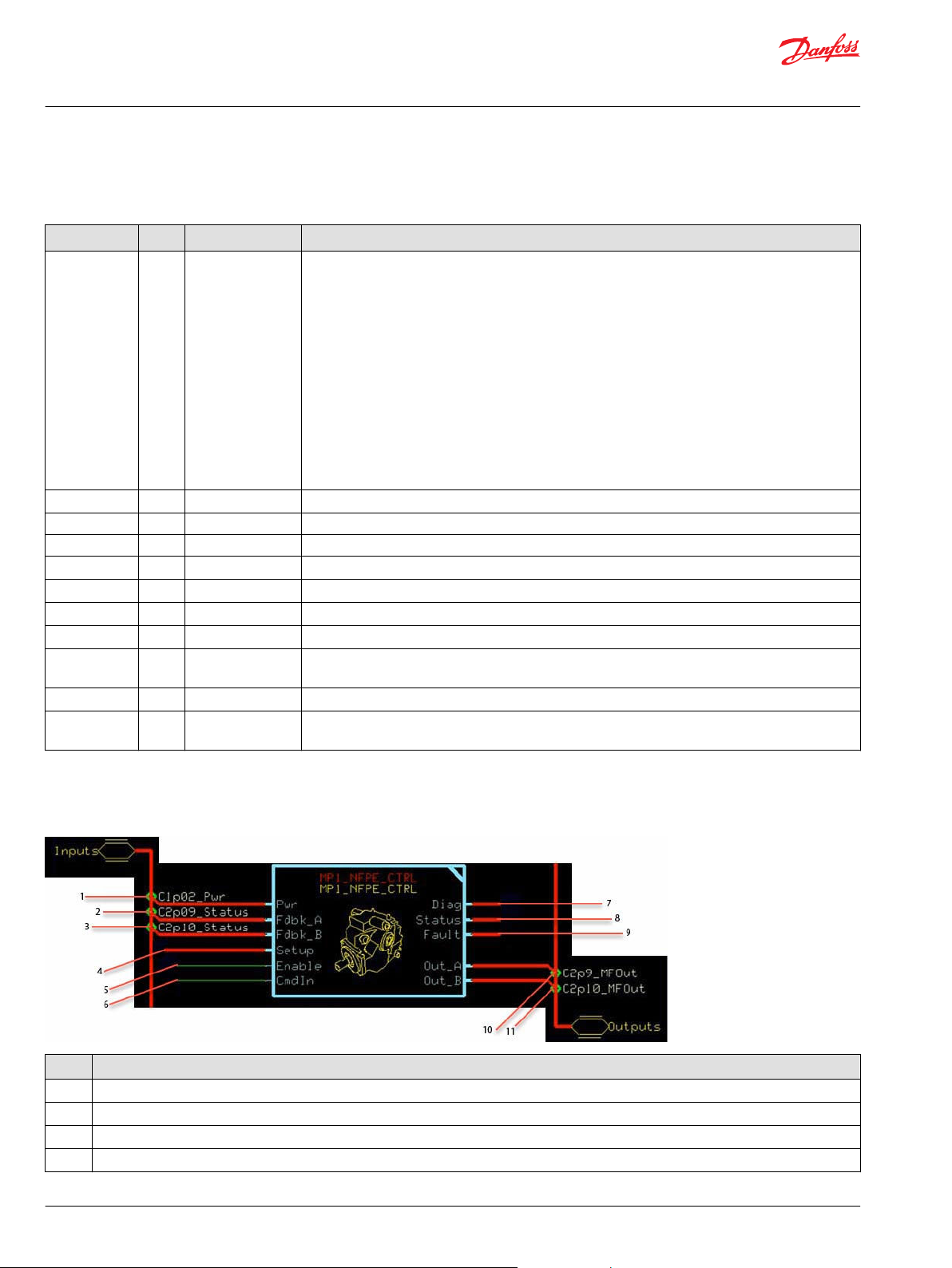
Function Block Connections
Connections you can make with the function block are described.
Item Description
1 Reports controller power supply voltage.
2 Reports the status of the MFOut (Multifunction Output) block that receives the function block’s Out_A.
3 Reports the status of the MFOut (Multifunction Output) block that receives the function block’s Out_B.
4 Allows common configuration values to be applied to multiple function blocks.
6 | © Danfoss | March 2018 AQ00000245en-US0102
Page 7
User Manual
PLUS+1® Compliant MP1 NFPE Function Blocks
MP1_12V_NFPE_CTRL and MP1_24V_NFPE_CTRL Function Blocks
Item Description
5
6
7 Outputs a bus with signals that report calibration values.
8 Reports the function block’s status.
9 Reports the function block's status
10 Outputs a bus with an OutputValue signal that drives the A coil.
11 Outputs a bus with an OutputValue signal that drives the B coil.
Status and Fault Logic
True = OutputValue signals (inside the Out_A and Out_B buses) follow the CmdIn signal.
•
False = Holds both OutputValue signals at zero.
•
False/True = Clears latched faults if CmdIn is zero.
•
+10,000 = Requests maximum Out_A output.
•
0 = Requests neutral (stop).
•
–10,000 = Requests maximum Out_B output.
•
Status and fault codes indicate the calibration state of the function block and how faults impact the
output values of the function block.
Status Logic
Function block status codes indicate the calibration state of the function block.
Status Hex
Block is not
calibrated.
Calibration active. 0x8002 0010 Enable is True and the CalTask = –2, –1, +1, or +2.
Parameters are
corrupt.
Invalid setup/
calibration.
Value too low. 0x8040
Value too high. 0x8080
*
Position of set bit in a 16 bit fault or status code. Bit 1 is the least significant bit. Bit 16 set to 1 identifies a standard Danfoss status code or fault code.
*
Binary Cause
0x8001 0001 Any CalFlag bit is set to 1.
0x8004 0100 (NV_EndCrnt > MaxCurr) or (NV_Thld × ThldMult) > EndCrntApplied for either direction A or
direction B.
The actual tests in the software are:
•
EndCrntApplied ≠ NV_EndCrnt—This happens when NV_EndCrnt > MaxCurr. It means that
EndCrntApplied = MaxCrnt.
•
ThldApplied = EndCrntApplied—This happens when (NV_Thld × ThldMult) ≥ EndCrntApplied).
0x8008
1000
0100 000
1000 000
Any of the following setup and configuration values are not within their valid ranges:
•
CalThldMin (for either direction).
•
CalThldMax (for either direction).
•
ThldMult.
•
FltDelay.
•
CalTask.
Also reported while PinStatus reports a configuration error (value =1) for either direction A or direction
B.
Threshold calibration is active and the OutputValue < CalThldMin for the calibration direction.
Threshold calibration is active and the OutputValue > CalThldMax for the calibration direction.
Fault Logic
This topic describes function block faults and how the faults affect OutputValue.
The function block’s Out_A and Out_B buses each contain an OutputValue signal that drives the
forward and reverse coils on the NFPE control.
©
Danfoss | March 2018 AQ00000245en-US0102 | 7
Page 8

User Manual
PLUS+1® Compliant MP1 NFPE Function Blocks
MP1_12V_NFPE_CTRL and MP1_24V_NFPE_CTRL Function Blocks
*
Fault Hex
Input value too low.
Input value too high. 0x8002 0010 CmdIn > +10,000.
Open circuit. 0x8004 0100 Measured Ω >
Short circuit. 0x0008 1000 Measured Ω <
Hardware. 0x8020 0010 0000 Current exceeds
General. 0x8040 0100 0000 Current flow
*
Position of set bit in a 16 bit fault or status code. Bit 1 is the least significant bit. Bit 16 set to 1 identifies a standard Danfoss status code or fault code.
†
A delayed fault gets reported if the detected fault condition persists for a specified delay time. A delayed fault cannot be cleared until the fault
0x8001 0001
Binary
Cause Response Delay
CmdIn < -10,000. OutputValue held
at 0.
(Nominal Ω x 3).
(Nominal Ω ÷ 3).
continuous or peak
rating.
between Out_A
and Out_B.
Possible cause is
loss of a common
ground
connection.
§
§
†
No. No. Fix CmdIn.
Yes. Yes. Check for open circuit or high
Latch
‡
Correction
resistance between output pin
and ground. See Function Block
Internal Constants for more
about Nominal Ω.
Check for short circuit or low
resistance between output pin
and ground. See Function Block
Internal Constants for more
about Nominal Ω.
Correct cause of overload.
Correct open ground
connection.
condition remains undetected for the delay time.
‡
A latched fault report maintains until the latch is released. A release is attempted each time that Enable becomes True while CmdIn is 0.
§
The nominal Ω value is an internal constant of each function block. It can be viewed, with other defined constants, in the Define sub-bus of the Diag
bus. The other constants specify the maximum current and the range limits for configuration values.
Configuration Values
The default Config page contains constant values that set the function block’s operating characteristics.
Typically, you do not have to change any of these values for the correct operation of the function block.
Optionally, you can:
•
Modify the constant values on this page.
•
Replace some or all of the constant values on this page with signals brought in on the Setup bus,
which is connected to the function block’s Setup input. For more information, see Modify the Config
Page.
8 | © Danfoss | March 2018 AQ00000245en-US0102
Page 9

User Manual
PLUS+1® Compliant MP1 NFPE Function Blocks
MP1_12V_NFPE_CTRL and MP1_24V_NFPE_CTRL Function Blocks
Default Values for MP1_12V_NFPE_CTRL Function Block
Default Values for MP1_24V_NFPE_CTRL Function Block
©
Danfoss | March 2018 AQ00000245en-US0102 | 9
Page 10

User Manual
PLUS+1® Compliant MP1 NFPE Function Blocks
MP1_12V_NFPE_CTRL and MP1_24V_NFPE_CTRL Function Blocks
Input Type 12V Range 24V Range Description
CalTask S16 –2 to +3 –2 to +3 CalTask (Calibration Task) selects a calibration process.
•
–2 = Calibrate the B end current.
•
–1 = Calibrate the B threshold.
•
0 = Not in the calibration mode.
•
+1 = Calibrate the A threshold.
•
+2 = Calibrate the A end current.
•
+3 = Applies default calibration values for both outputs on a
transition to +3. The default value of +3 applies default
values each time the controller powers up, and allows normal
operation.
StoreCalVal BOOL —— —— While calibration is active, a StoreCalVal (Store Calibration
Value) False/True transition writes the selected calibration value
to memory and sets the CalFlg to indicate this value as
calibrated.
The CalFlg in the Diag bus reports the status of each calibration
value.
•
True = Not calibrated.
•
False = Calibrated.
SetCalReqd BOOL —— —— A False/True transition sets all CalFlg bits to 1 to mark all
calibration values as uncalibrated.
ClrCalReqd BOOL —— —— A False/True transition clears all CalFlg bits to 0 to mark all
calibration values as calibrated.
CalThldMin U16 0–7,199 0–3,679 Sets the lower limit of the valid range for the threshold
parameters.
10,000 = 1,000 mA.
CalThldMax U16 7,200–10,800 3,680–5,520 Sets the upper limit of the valid range for the threshold
parameters.
10,000 = 1,000 mA.
ThldMult U16 0–10,000 0–10,000 The function block multiplies the Out_A and Out_B thresholds
by the ThldMult (Threshold Multiplier) to calculate the applied
threshold.
Enter a value of less than 10,000 to reduce the applied
threshold. For example, a value of 7,500 reduces both the
Out_A and Out_B thresholds by 25%.
10,000 = 100.00%.
DfltThld_A U16 CalThldMin to CalThldMax CalThldMin to CalThldMax When the CalTask becomes +3, the Out_A threshold
parameter resets to equal the DfltThld_A(Default Threshold A).
10,000 = 1,000 mA.
DfltThld_B U16 CalThldMin to CalThldMax CalThldMin to CalThldMax When the CalTask becomes +3, the Out_B threshold parameter
resets to equal the DfltThld_B(Default Threshold B).
10,000 = 1,000 mA.
DfltEndCrnt_A U16 0–1,800 0–920 When the CalTask becomes +3, the Out_A end current
parameter resets to equal the DfltEndCrnt_A (Default End
Current A).
10,000 = 1,000 mA.
DfltEndCrnt_B U16 0–1,800 0–920 When the CalTask becomes +3, the Out_B end current
parameter resets to equal the DfltEndCrnt_B (Default End
Current B).
10,000 = 1,000 mA.
Orientation
U8 0–3 0–3
Where the control is mounted to the pump.
0=Top
1=Left
2=Right
3=Bottom
Orientation only affects the default values used for a pump.
10 | © Danfoss | March 2018 AQ00000245en-US0102
Page 11

User Manual
PLUS+1® Compliant MP1 NFPE Function Blocks
MP1_12V_NFPE_CTRL and MP1_24V_NFPE_CTRL Function Blocks
Input Type 12V Range 24V Range Description
EnFltDet BOOL —— —— The EnFltDet (Fault Detection) signal enables detection of open
and short conditions, based on the measured resistance of the
EDC control circuit.
•
True = Enable fault detection.
•
False = Disable fault detection.
FltDetectTm U16 100–2,000 100–2,000 Sets the time before the fault detection logic reports or clears
fault conditions.
This value specifies how long a fault condition must be
detected before it is reported. It also specifies how long the
fault condition must remain undetected before the report can
be cleared.
1,000 = 1,000 ms.
ResFltCurr U16 —— —— For each direction, the open and short faults are only detected
while the OutputValue exceeds the Resistance Fault Current.
Typically, set this value below the Out_Aand Out_B threshold
values.
If you set the value:
•
Too low, you get nuisance faults.
•
Too high, you turn off fault detection for some or all of the
output range.
1,000 = 100.0 mA.
NegCrntThld U16 —— —— Negative feedback current in an uncommanded direction must
be greater than the NegCrntThld (Negative Current Threshold)
value to set a fault.
Typically, this fault results when the A and B outputs drive coils
that share a common ground and their connection to the
controller ground is lost.
1,000 = 100.0 mA.
FdbkFltrTime U16 —— —— Sets the time constant for the exponential filtering applied to
the current measurement used to detect a fault caused by
negative feedback in an uncommanded direction.
1,000 = 1,000 ms.
Modify the Config Page
You can modify the Config page to control the configuration process with signals routed into the
function block from an application.
The following figure shows the changes made to the Config page to allow an application to control the
configuration process using signals routed via the Setup bus.
©
Danfoss | March 2018 AQ00000245en-US0102 | 11
Page 12

User Manual
PLUS+1® Compliant MP1 NFPE Function Blocks
MP1_12V_NFPE_CTRL and MP1_24V_NFPE_CTRL Function Blocks
Relationship between Function Block Input and Output Signals
This topic describes the relationship between the function block’s CmdIn and OutputValue.
The function block’s Out_A and Out_B buses each contain an OutputValue signal.
12 | © Danfoss | March 2018 AQ00000245en-US0102
Page 13

User Manual
PLUS+1® Compliant MP1 NFPE Function Blocks
MP1_12V_NFPE_CTRL and MP1_24V_NFPE_CTRL Function Blocks
The Thld_A value sets the Out_A OutputValue of the block when it receives CmdIn of +1.
•
The Thld_B value sets the Out_B OutputValue of the block when it receives CmdIn of –1.
•
The EndCrnt_A value sets the Out_A OutputValue of the block when it receives CmdIn of +10000.
•
The EndCrnt_B value sets the Out_B OutputValue of the block when it receives CmdIn of –10000.
•
Calibrate the Function Block
This topic describes how to calibrate the function block.
See Modify the Config Page for an example of a Config page that has been modified to allow an
application to control the calibration process.
1. Prepare to calibrate.
a) Set the SetCalReqd signal to False.
b) Set the ClrCalReqd signal to False.
c) Set the StoreCalVal signal to False.
d) Toggle the SetCalReqd signal from False to True.
Toggling sets the “not calibrated” bits in the CalFlg signal to 1.
2. Set the Enable signal to True.
3. Calibrate the Out_A threshold parameter.
a) Set the CalTask signal to +1.
b) Gradually modify the CmdIn signal in a positive (0 to +10,000) direction to find the minimum
command that causes motion.
In the Status signal, monitor bit 7—Value too low and bit 8—Value too high to make sure that
the OutputValue signal is within the valid threshold range.
c) Toggle the StoreCalVal signal from False to True to write the OutputValue to memory.
In the CalFlg signal, check that bit 1 clears to 0, to verify that the controller has written the Out_A
threshold parameter to memory.
4. Calibrate the Out_B threshold parameter.
a) Set the CalTask signal to –1.
b) Gradually modify the CmdIn signal in a negative (0 to –10,000) direction to find the minimum
command that causes motion.
In the Status signal, monitor bit 7—Value too low and bit 8—Value too high to make sure that
the OutputValue signal is within the valid threshold range.
c) Toggle the StoreCalVal signal from False to True to write the OutputValue to memory.
In the CalFlg signal, check that bit 3 clears to 0, to verify that the controller has written the Out_B
threshold parameter to memory.
©
Danfoss | March 2018 AQ00000245en-US0102 | 13
Page 14

User Manual
PLUS+1® Compliant MP1 NFPE Function Blocks
MP1_12V_NFPE_CTRL and MP1_24V_NFPE_CTRL Function Blocks
5. Calibrate the Out_A end current parameter.
a) Set the CalTask signal to +2.
b) Gradually modify the CmdIn signal in a positive direction to find the command that produces the
desired maximum pump flow.
c) Toggle the StoreCalVal signal from False to True to write the OutputValue to memory.
In the CalFlg signal, check that bit 2 clears to 0, to verify that the controller has written the Out_A
end current parameter to memory.
6. Calibrate the Out_B end current parameter.
a) Set the CalTask signal to –2.
b) Gradually modify the CmdIn signal in a negative direction to find the command that produces the
desired maximum pump flow.
c) Toggle the StoreCalVal signal from False to True to write the OutputValue to memory.
In the CalFlg signal, check that bit 4 clears to 0, to verify that the controller has written the Out_B
end current parameter to memory.
7. End the calibration process.
a) Set the CalTask signal to 0.
b) In the CalFlg signal, verify that all bits are now 0.
c) Verify that no Status or Fault conditions are reported.
d) Set the ThldMult signal to the desired value.
Calibrate an Individual Parameter
You can use the PLUS+1® Service Tool to manually calibrate the function block by downloading
calibration parameters.
Partial calibration allows you to calibrate an individual parameter while leaving the values of other
parameters unchanged.
1. Prepare to calibrate.
a) Set the SetCalReqd signal to False.
b) Set the ClrCalReqd signal to False.
c) Set the StoreCalVal signal to False.
d) Toggle the SetCalReqd signal from False to True.
Toggling sets all the “not calibrated” bits in the CalFlg signal to 1.
2. Set the Enable signal to True.
3. Use the CalTask signal to select the parameter to be calibrated.
4. Calibrate the parameter.
a) Toggle the StoreCalVal signal from False to True to write the OutputValue to memory.
b) In the CalFlag signal, check that the calibration bit for the selected parameter clears to 0; this
verifies that the controller wrote the parameter to memory.
5. End the calibration process.
a) Set the CalTask signal to 0.
b) Toggle the ClrCalReqd signal from False to True.
c) In the CalFlg signal, verify that all bits are now 0.
d) Verify that no Status or Fault conditions are reported.
14 | © Danfoss | March 2018 AQ00000245en-US0102
Page 15

W
User Manual
PLUS+1® Compliant MP1 NFPE Function Blocks
MP1_12V_NFPE_CTRL and MP1_24V_NFPE_CTRL Function Blocks
Calibrate Function Block Manually
You can use the PLUS+1® Service Tool to manually calibrate the function block by downloading
calibration parameters.
Warning
Using the PLUS+1® Service Tool to download new parameter values to an application can result in
unexpected and sudden machine movements.
Unexpected and sudden machine movements can result in personal injury and equipment damage.
Always secure your machine against unexpected and sudden movements before you use the Service
Tool program to download new parameter values.
When you manually calibrate:
Make sure that the calibration parameters are valid. If the values are out of range for a given direction,
•
the block limits the values of ThldApplied, EndCrntApplied or both for that direction. This condition
is indicated by the “Parameters are corrupt” Status, but it can produce unintended output
commands.
Verify that the Status signal indicates normal status conditions.
•
Using Namespaces
Namespaces can help you successfully compile an application that uses the same function block more
than once.
Change each function block's namespace by setting its Name Space value to something unique. If you
do not change the Name Space value, you cannot compile the application.
The Name Space value adds a unique prefix to each component name.
Also, if you want to use these function blocks' companion Service Tool screens, you must include the
function block's advanced checkpoint with namespace in the application's compiled .lhx file. Use the
function block's Checkpoints page to include the checkpoint.
Change Name Space Value
To successfully compile your application, change the Name Space value for function blocks that are used
more than once in an application.
©
Danfoss | March 2018 AQ00000245en-US0102 | 15
Page 16

User Manual
PLUS+1® Compliant MP1 NFPE Function Blocks
MP1_12V_NFPE_CTRL and MP1_24V_NFPE_CTRL Function Blocks
1. In the PLUS+1® GUIDE menu bar, click the Query/Change button.
2. Click on the function block whose namespace you want to set to a unique value.
The Edit Page window opens.
3. In the Edit Page window, enter a meaningful Name Space value.
Name Space values are case-sensitive.
•
To save controller memory, use a short Name Space value.
•
4. Press Enter.
5. Repeat these steps to enter unique Name Space values for other identical function blocks.
Include Advanced Checkpoint with Namespace in Compiled Application
Make all of a function block's input, output and internal signals available to the Service Tool.
Each function block has an Advanced Checkpoint with Namespace page that you can edit to ensure
unique namespaces are included in the application's companion screens for the Service Tool.
1. Enter the function block.
2. On the Checkpoints CP page, ensure the Chkpt signal is set to T.
3. To set the value to true:
a) Select the chkpt signal.
The Edit Value window opens.
b) Select T from the drop-down menu.
16 | © Danfoss | March 2018 AQ00000245en-US0102
Page 17

User Manual
PLUS+1® Compliant MP1 NFPE Function Blocks
MC Controller Configurations
Configure the controller to accept the input and output of the function block.
This function block:
Receives its Pwr, Fdbk_A, and Fdbk_B signals through your controller's inputs.
•
Outputs its Out_A and Out_B signals through your controller's outputs.
•
The following tables identify the controller inputs and outputs that you must modify to input and output
these signals.
Input Configurations
Function Block Input Compatible Controller Input Type Controller Input Configuration Action
Fdbk_A MFOut
Fdbk_B MFOut Pair with the MFOut used by the function block's Out_B.
*
Inside the Inputs page; outputs a Status bus that reports the state of a corresponding MFOut inside the Outputs page.
Output Configurations
Function Block Output Compatible Controller Output Type Controller Output Configuration Action
Out_A MFOut
Out_B
*
Pair with the MFOut used by the function block's Out_A.
Delete the:
•
OutputValue route.
‒
PinConfig route.
‒
In the Group for the MFOut change the:
•
CurChgLim value to 80 for 12V function blocks.
‒
CurChgLim value to 50 for 24V function blocks.
‒
ReqFreg value to 100 for both 12V and 24V function blocks.
‒
©
Danfoss | March 2018 AQ00000245en-US0102 | 17
Page 18

User Manual
PLUS+1® Compliant MP1 NFPE Function Blocks
MC Controller Configurations
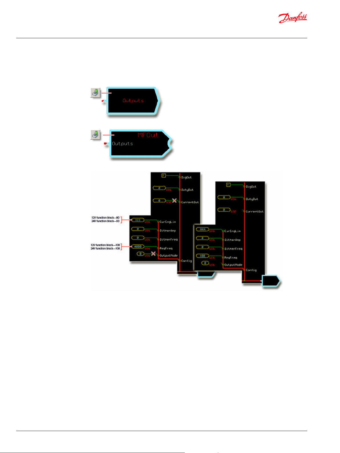
Configure an MFOut for Out_A and Out_B
Configure MFOut to receive the function block's output.
1. In the GUIDE template, enter the Outputs page.
2. In the Group that receives the function block's output signal, make the changes that are shown in the
following figure.
3. Enter the MFOut that receives the function block’s output signal.
4. In the MFOut that receives the function block's output signal, make the changes that are shown
below.
18 | © Danfoss | March 2018 AQ00000245en-US0102
Page 19
User Manual
PLUS+1® Compliant MP1 NFPE Function Blocks
SC Controller Configurations
Configure the controller to accept the input and output of the function block.
This function block:
Receives its Pwr, Fdbk_A, and Fdbk_B signals through your controller's inputs.
•
Outputs its Out_A and Out_B signals through your controller's outputs.
•
The following tables identify the controller inputs and outputs that you must modify to input and output
these signals.
Input Configurations
Function Block Input Compatible Controller Input Type Controller Input Configuration Action
Fdbk_A MFOut
Fdbk_B MFOut Pair with the MFOut used by the function block's Out_B.
*
Inside the Inputs page; outputs a Status bus that reports the state of a corresponding MFOut inside the Outputs page.
Output Configurations
Function Block Output Compatible Controller Output Type Controller Output Configuration Action
Out_A MFOut
Out_B
*
Pair with the MFOut used by the function block's Out_A.
Delete the:
•
OutputValue route.
‒
PinConfig route.
‒
In the Group for the MFOut change the:
•
CurChgLim value to 80 for 12V function blocks.
‒
CurChgLim value to 50 for 24V function blocks.
‒
ReqFreg value to 100 for both 12V and 24V function blocks.
‒
©
Danfoss | March 2018 AQ00000245en-US0102 | 19
Page 20
User Manual
PLUS+1® Compliant MP1 NFPE Function Blocks
SC Controller Configurations
Configure an MFOut for Out_A and Out_B
Make changes so the controller accepts the output of the function block.
1. In the GUIDE template, enter the Outputs page.
2. Enter the MFOut that receives the function block’s output signal.
3. Make the changes that are shown in the following figure.
20 | © Danfoss | March 2018 AQ00000245en-US0102
Page 21

User Manual
PLUS+1® Compliant MP1 NFPE Function Blocks
Customizable Service Screens
This function block comes with pre-made service screens that you can customize when building your
Service Tool application.
The pre-made screens simplify the task of creating Service Tool applications. You can use the screens as
is. Or, if desired, you can use the Reuseable Panels screen to choose which screen components you want
to place in your application.
Refer to the PLUS+1® GUIDE Service Tool Design Manual (Danfoss document number L1320837) for more
information on how to create Service Tool screens.
Pre-Made Service Screen Panel Components
This topic describes pre-made components that you can use to quickly build your organization's service
tool application.
©
Danfoss | March 2018 AQ00000245en-US0102 | 21
Page 22
User Manual
PLUS+1® Compliant MP1 NFPE Function Blocks
Customizable Service Screens
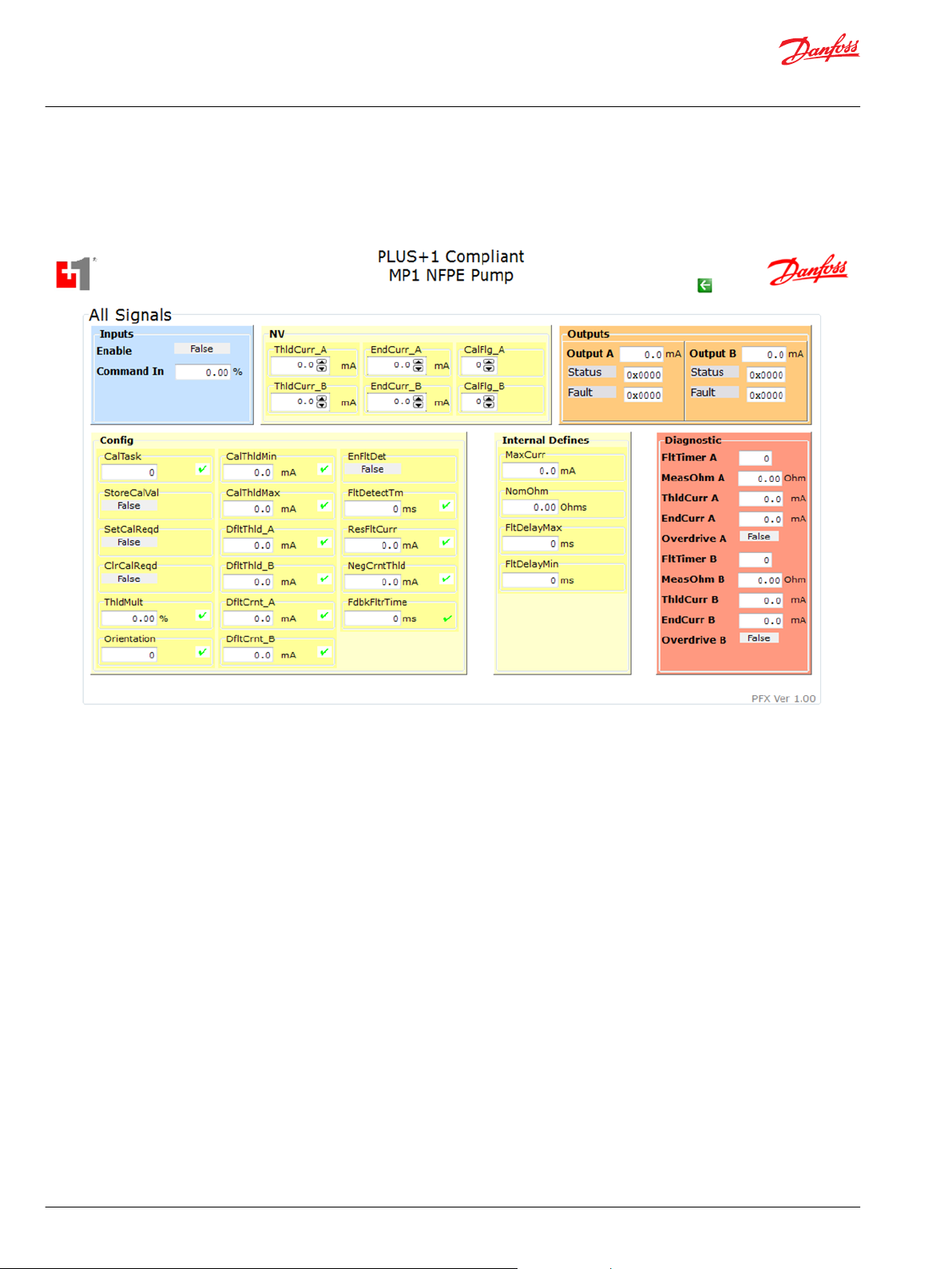
All Signals Service Screen
This topic describes pre-made components that you can use in your application to see the status of all
signals of the function block.
22 | © Danfoss | March 2018 AQ00000245en-US0102
Page 23
User Manual
PLUS+1® Compliant MP1 NFPE Function Blocks
Customizable Service Screens
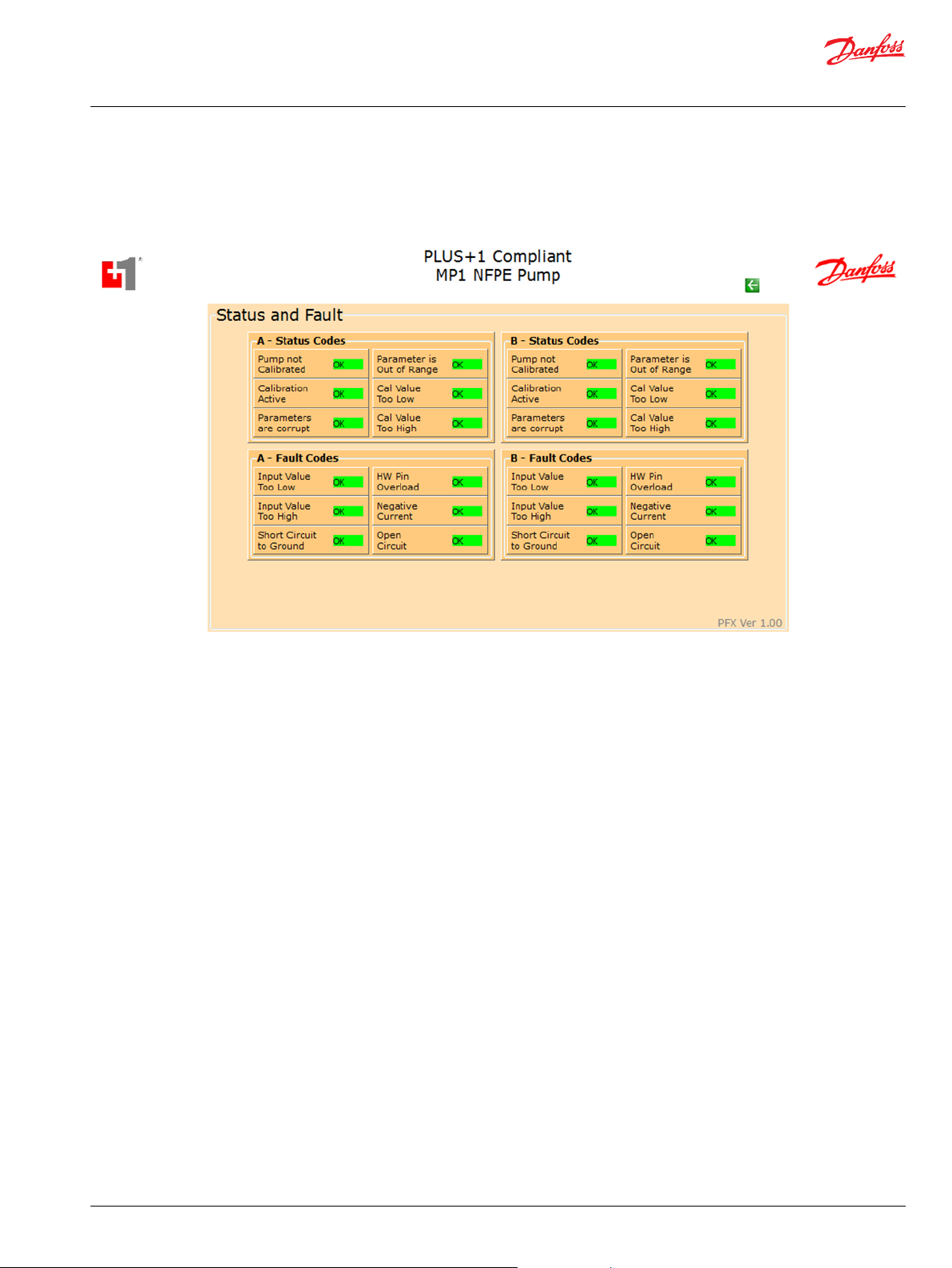
Status and Fault Codes Service Screen
This topic describes pre-made components that you can use in your service tool application to view
status codes and fault codes.
©
Danfoss | March 2018 AQ00000245en-US0102 | 23
Page 24
User Manual
PLUS+1® Compliant MP1 NFPE Function Blocks
Customizable Service Screens
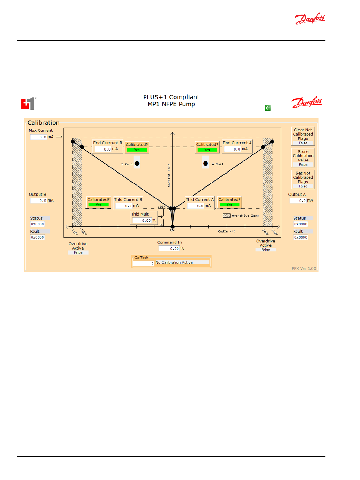
Calibration Service Screen
This topic describes pre-made components that you can use in your application to determine how the
function block has calibrated the pump.
24 | © Danfoss | March 2018 AQ00000245en-US0102
Page 25
User Manual
PLUS+1® Compliant MP1 NFPE Function Blocks
Customizable Service Screens
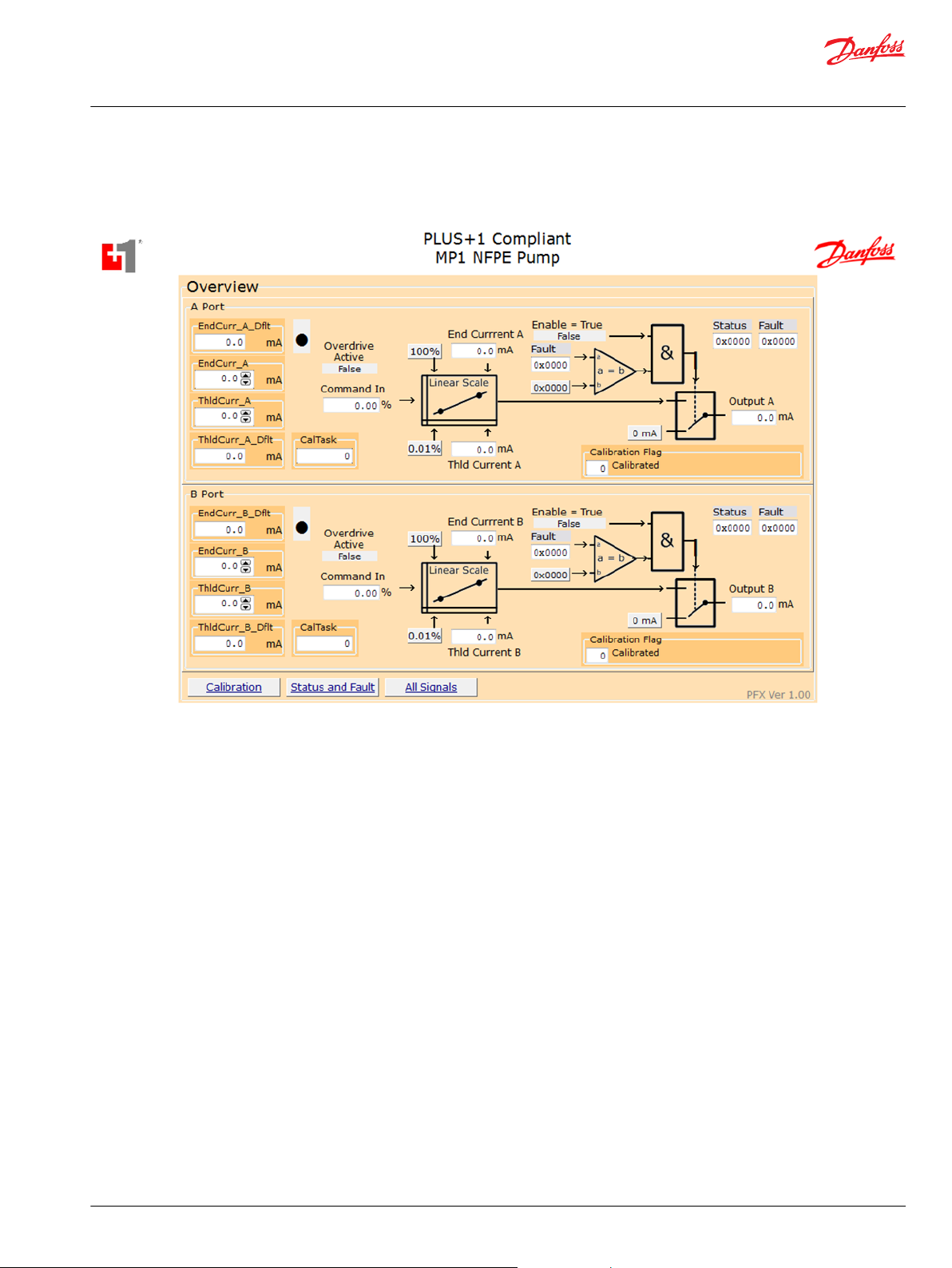
Overview Service Screen
The Overview page shows the simplified block diagram of the function.
©
Danfoss | March 2018 AQ00000245en-US0102 | 25
Page 26

User Manual
PLUS+1® Compliant MP1 NFPE Function Blocks
26 | © Danfoss | March 2018 AQ00000245en-US0102
Page 27

User Manual
PLUS+1® Compliant MP1 NFPE Function Blocks
©
Danfoss | March 2018 AQ00000245en-US0102 | 27
Page 28

Danfoss
Power Solutions GmbH & Co. OHG
Krokamp 35
D-24539 Neumünster, Germany
Phone: +49 4321 871 0
Danfoss
Power Solutions ApS
Nordborgvej 81
DK-6430 Nordborg, Denmark
Phone: +45 7488 2222
Danfoss
Power Solutions (US) Company
2800 East 13th Street
Ames, IA 50010, USA
Phone: +1 515 239 6000
Danfoss
Power Solutions Trading
(Shanghai) Co., Ltd.
Building #22, No. 1000 Jin Hai Rd
Jin Qiao, Pudong New District
Shanghai, China 201206
Phone: +86 21 3418 5200
Products we offer:
Comatrol
www.comatrol.com
Turolla
www.turollaocg.com
Hydro-Gear
www.hydro-gear.com
Daikin-Sauer-Danfoss
www.daikin-sauer-danfoss.com
Bent Axis Motors
•
Closed Circuit Axial Piston
•
Pumps and Motors
Displays
•
Electrohydraulic Power
•
Steering
Electrohydraulics
•
Hydraulic Power Steering
•
Integrated Systems
•
Joysticks and Control
•
Handles
Microcontrollers and
•
Software
Open Circuit Axial Piston
•
Pumps
Orbital Motors
•
PLUS+1® GUIDE
•
Proportional Valves
•
Sensors
•
Steering
•
Transit Mixer Drives
•
Danfoss Power Solutions is a global manufacturer and supplier of high-quality hydraulic and
electronic components. We specialize in providing state-of-the-art technology and solutions
that excel in the harsh operating conditions of the mobile off-highway market. Building on
our extensive applications expertise, we work closely with our customers to ensure
exceptional performance for a broad range of off-highway vehicles.
We help OEMs around the world speed up system development, reduce costs and bring
vehicles to market faster.
Danfoss – Your Strongest Partner in Mobile Hydraulics.
Go to www.powersolutions.danfoss.com for further product information.
Wherever off-highway vehicles are at work, so is Danfoss. We offer expert worldwide support
for our customers, ensuring the best possible solutions for outstanding performance. And
with an extensive network of Global Service Partners, we also provide comprehensive global
service for all of our components.
Please contact the Danfoss Power Solution representative nearest you.
Local address:
Danfoss can accept no responsibility for possible errors in catalogues, brochures and other printed material. Danfoss reserves the right to alter its products without notice. This also applies to products
already on order provided that such alterations can be made without changes being necessary in specifications already agreed.
All trademarks in this material are property of the respective companies. Danfoss and the Danfoss logotype are trademarks of Danfoss A/S. All rights reserved.
©
Danfoss | March 2018 AQ00000245en-US0102
 Loading...