

Page 1
Instructions for installation and use
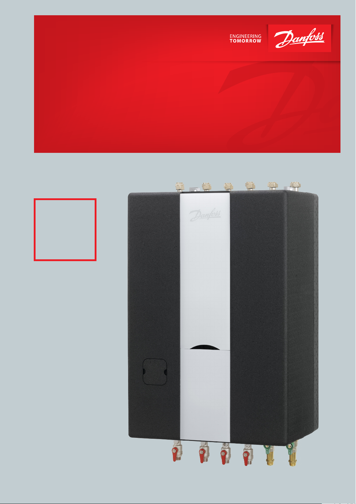
Indirect, fully insulated district heating subtations Akva
Lux II VXi, VXi Solo
Indirect district heating substation for heating and domestic hot water.
VXi
Fully insulated
for very low
heat losses.
www.danfoss.com
Page 2
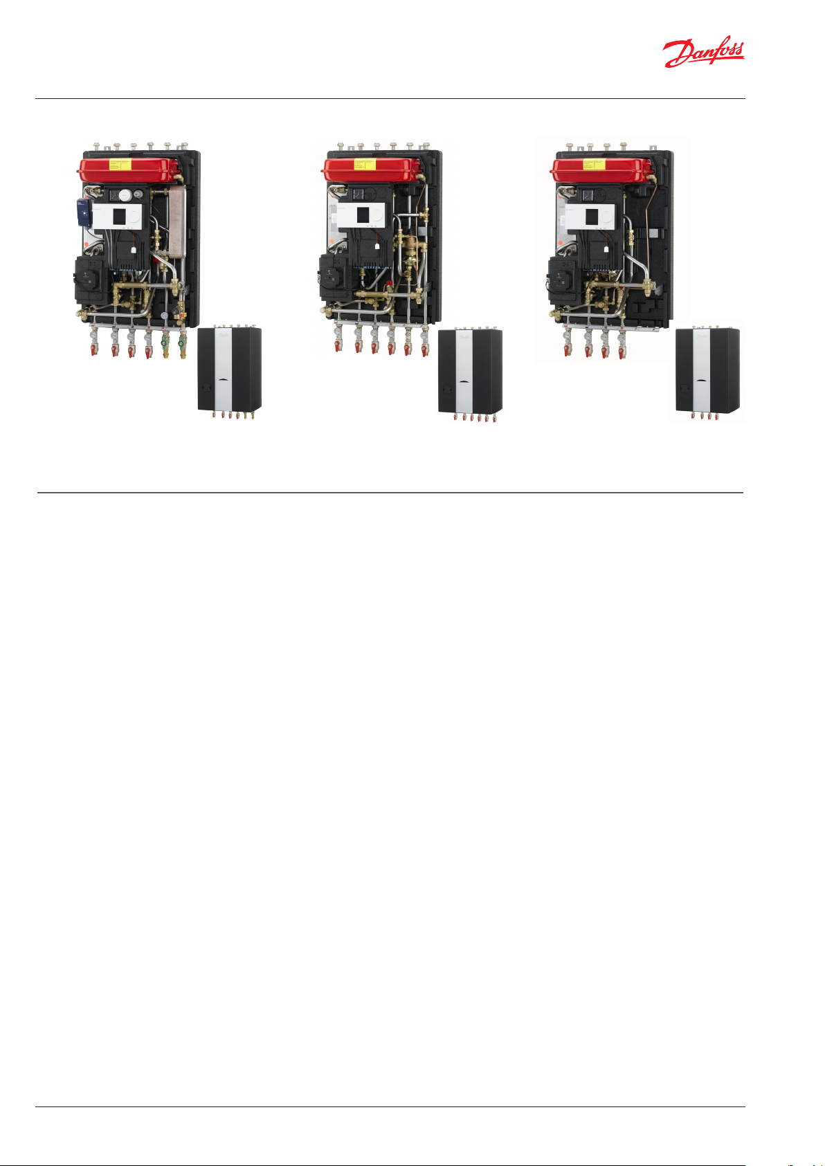
Instructions for installation and use Akva Lux II VXi, VXi Solo HWP, VXi Solo H
Akva Lux II VXi VXi Solo HWP VXi Solo H
1.0 Content
2.0 Installation instructions, safety and handling ...............................................................................................................................................................3
3.0 Getting started - Quick guide for easy start-up ............................................................................................................................................................ 4
4.0 Main components / Connections ......................................................................................................................................................................................6
5.0 Diagrams, Dimensional sketches, Examples ..................................................................................................................................................................8
6.0 General, Mounting of heat meter and safety valves ................................................................................................................................................ 11
7.0 Filling the system with water ........................................................................................................................................................................................... 12
8.0 Variable connection possibilities .................................................................................................................................................................................... 13
9.0 Recirculation (only Akva Lux II VXi) ................................................................................................................................................................................ 14
10.0 Electricical connections ...................................................................................................................................................................................................... 15
11.0 Adjustmend and commissioning ................................................................................................................................................................................... 16
12.0 Heating circuit, Danfoss ECL 210/310 automatics .................................................................................................................................................... 17
13.0 Control of heating circuit ................................................................................................................................................................................................... 18
14.0 Heating circuit, pump and summer operation .......................................................................................................................................................... 20
15.0 Domestic hot water ............................................................................................................................................................................................................. 22
16.0 Maintenance........................................................................................................................................................................................................................... 24
17.0 Troubleshooting ...................................................................................................................................................................................................................26
18.0 EU Declaration of conformity ........................................................................................................................................................................................... 30
19.0 Commissioning Certificate ................................................................................................................................................................................................ 31
2 | © Danfoss | Produced by Danfoss Redan A/S | 2017.01
VI.JV.R1.02
Page 3
Instructions for installation and use Akva Lux II VXi, VXi Solo HWP, VXi Solo H
. INSTALLATION INSTRUCTIONS, SAFETY AND HANDLING
Instructions
Please read these instructions carefully before installing and comissioning this substation. The manufacturer accepts no liability for loss or
damage resulting from failure to comply with these instructions for use.
Read and follow these instructions carefully to prevent the risk of physical injury and/or damage to peroperty. Exceeding the recommended
operating parameters considerably increases the risk of personal injury
and/or damage to property. Installation, commissioning and maintenance must be carried out by qualified and authorized personnel in
compliance with the local safety regulations.
Once the station has been installed and is operating, there is normally
no need to alter the settings or other functions. The district heating
substation is very reliable and easy to operate.
Energy source
The substation is primarily designed for connection to district heating.
Alternative energy sources can be used if the operating conditions are
equivalent to district heating at all times.
Application
The substation is designed only to operate with water and other heating
media may not be used.
The substation is to be connected to the household piping in a frost-free
room, where the temperature does not exceed 50 °C and the relative
humidity is not higher than 80%. The substation must no be covered,
bricked in or otherwise cut off from access.
Choise of materials
Only use materials, that comply with local regulations.
Corrosion
The maximum chloride compounds of the medium must not be higher
than 300 mg/l. The risk of corrosion increases considerably if the recommended chloride content is exceeded.
Safety valve(s)
Installation of safety valve(s) must always be in compliance with local regulations.
Noise level.
≤ 55 dB.
Connection
It must be possible to cut off all energy sources to the unit - including
electrical connections - at all times. The unit must be connected to an
electrical equalizer connection.
Potential equalization/grounding
Potential equalization is an electrical equalizer connection to secure
against user contact with dangerous voltage, which may occur for example between two piping systems. Potential equalization reduces
corrosion in heat exchangers, water heaters, district heating units and
plumbing installations.
Potential bonding should be carried out according to 60364-4-41:
2007 and IEC 60364-5-54: 2011.
Bonding poing is marked on the mounting plate below right corner
with an earthing symbol and there will be a hole in the station mounting plate and a label with earth symbol.
Warning! Hot surfaces
Parts of the substation may be very hot and can cause burn injuries.
Be very careful when you are in the immediate vicinity of the substation.
Warning of high pressure and high temperature
The maximum supply temperature in the district heating network
can be up to 120°C and the operating pressure can be up to 16 bar.
This may result in a risk of scalding from touching the substation and
from outflow of the medium (water/steam). Exceeding the substation design data and operating parameters for pressure and temperature carries an appreciable risk of personal injury and/or damage
to property.
Emergencies
In the event of fire, leaks or other hazards, immediately shut off all
sources of energy to the substation, if possible and call for appropriate assistance.
If the domestic hot water is discoloured or malodorous, shut off all
ball valves on the substation, notify all users and call for professional
assistance immediately.
PTC2+P controller for domestic hot water
The controller is preset from factory and sealed with a
red sticker. This sealing must not been broken.
The warranty becomes void if the sealing is broken.
Storage
Before installation, the units must be stored in a dry, heated (i.e. frostfree) room.
(Relative humidity max. 80% and storage temperature 5-70 °C).
The units must not be stacked higher than the limit at the factory (max.
8 layers) Units supplied in cardboard packaging must be lifted using the
handles incorporated in the packaging. Units must be placed on pallets
for transport/moving across large distances.
As far as possible, do not lift the substation by the pipes. Lifting by the
pipes may cause leaks. REMEMBER to retighten.
Disposal
Dispose of the packaging in accordance with the local regulations for
disposal of used packaging materials.
The substation is made of materials that cannot be disposed of together
with household waste.
Close all energy sources and disconnect all connection pipes. Disconnect
and dismantle the product for disposal in accordance with the applicable
local regulations for the disposal of the individual components.
VI.JV.R1.02
Warning of damage during transport
On reception of the substation, and before installing it, check for any
evidence of damage during transport.
The substation must be handled and moved with the greatest care
and attention.
IMPORTANT - Tightening of connections
Before adding water to the system, ALL pipe connections MUST be
retightened, as vibrations during transport may have caused leaks.
Once the substation has been filled and the system has been put into
operation, ALL pipe connections MUST be tightened once more.
(Do not overtighten! - See page 8, Test and Connections)
Handling
We recommend that you wear suitable safety footwear while
handling and installing the substation.
NOTE: Interventions/rework on our components results in loss of
warranty.
© Danfoss | Produced by Danfoss Redan A/S | 2017.01 | 3
Page 4

Instructions for installation and use Akva Lux II VXi, VXi Solo HWP, VXi Solo H
. GETTING STARTED QUICK GUIDE FOR EASY STARTUP
Mounting
Connect the substation to the household piping in accordance with
the labelling at the bottom and/or in accordance with the instructions
in this manual. Upon delivery the substation is prepared for connection in bottom of the substation, but can also be established in top.
If the household piping system features domestic hot water
recirculation, the substation must be connected to the recirculation
system. The circulation set for recirculation connection is not standard
equipment. The set must be purchased as extra equipment.
We recommend establishing recirculation BEFORE mounting the
substation on the wall.
For instructions about recirculation connection, see page 14.
GETTING STARTED is a quick guide and some details in connection with
installation and commissioning may require additional information,
which can be found elsewhere in this instruction manual.
GETTING STARTED AKVA LUX II VXi
The VXi substations offer variable connection possibilities, as connections of pipes can be established in the top or in the bottom of the
substation.- Upon delivery the substation is prepared for connection
in bottom of the substation. For change of connection from bottom
to top, demount plugs on connection pipes in top of substation and
ball valves on connection pipes in bottom of substation, and mount
plugs in connection pipes in bottom of substation. See page 13 for
further information.
For connection in TOP for DCW and DHW please note that this
includes relocation of the built-in blind plates BEFORE mounting
the substation on the wall. (Please see instruction on page 13 for
further information).
If the household piping system features domestic hot water recirculation, the substation must be connected to the recirculation system,
- according to instructions on page 14.
1. Mount the substation on a solid wall using two sturdy bolts (max. 8
mm), screws, expansion bolts or similar.
Note!
Heating and cooling the substation may cause leaks. Therefore
it may be necessary to retighten the connections in the period
after commissioning.
Note!
Never lift the station by its front insulation cover!
GETTING STARTED - VXi Solo HWP / VXi Solo H
The VXi substations offer variable connection possibilities, as connections of pipes can be established in the top or in the bottom of the
substation.- Upon delivery the substation is prepared for connection
in bottom of the substation. For change of connection from bottom to
top, demount plugs on connection pipes in top of substation and ball
valves on connection pipes in bottom of substation, and mount plugs
in connection pipes. See page 10 for further information.
For connection in TOP for DCW and DHW please note that this
includes relocation of the built-in blind plates BEFORE mounting
the substation on the wall. (Please see instruction on page 13 for
further information).
1. Mount the substationon a solid wall using two sturdy bolts (max. 8
mm), screws, expansion bolts or similar.
2. Tighten all pipe connections, as they may have loosened during
transport and handling.
3. Mount the district heating meter (see page 11).
2. Tighten all pipe connections, as they may have loosened during
transport and handling.
3. Mount the district heating meter (see page 11).
4. On systems that feature a safety valve, establish a drain connection
in compliance with the applicable legislation.
5. Fill the heat exchanger / the system with water according to the
instructions on page 12.
6. Open the ball valve for the HE supply and return flow, as well as the
DHW outlet and heat up the system.
7. Check the substation and the household piping thoroughly for leaks.
8. Pressure test the entire system for leaks in accordance with the applicable regulations.
Connect pump and automatic components, if any, to the electricity
9.
supply, but do not switch on the power.
10. Heat the system and vent the radiator circuit/heating side thoroughly on the radiators and the air valve, if any.
11. Connection
Now switch on the pump and automatic components, if any.
12. Finish by adjusting the substation in accordance with the instruction manuals and remember to fill out the Commissioning Certificate
page 31.
4. On systems that feature a safety valve, establish a drain connection
in compliance with the applicable legislation.
5. Fill the heat exchanger / the system with water according to the
instructions on page 12.
6. Open the ball valve for the HE supply and return flow and heat up
the system.
7. Check the substation and the household piping thoroughly for leaks.
8. Pressure test the entire system for leaks in accordance with the applicable regulations.
Connect pump and automatic components, if any, to the electricity
9.
supply, but do not switch on the power.
10. Heat the system and vent the radiator circuit/heating side thoroughly on the radiators and the air valve, if any.
11. Connection
Now switch on the pump and automatic components, if any.
12. Finish by adjusting the substation in accordance with the instruction manuals and remember to fill out the Commissioning Certificate
page 31.
4 | © Danfoss | Produced by Danfoss Redan A/S | 2017.01
VI.JV.R1.02
Page 5
Instructions for installation and use Akva Lux II VXi, VXi Solo HWP, VXi Solo H
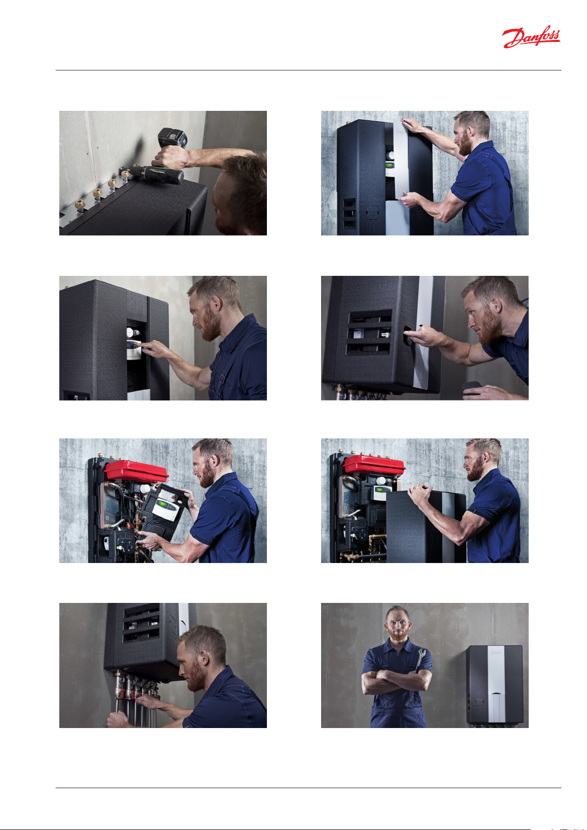
The station is easily mounted on the wall. It is recommended
that at least two people are involve in the installation.
Note: Never lift the unit by its front insulation cover!
Easy access for setting the ECL 210/310 controller.
By removing the white front panel, easy access is provided to the display and components for regulatory and
maintenance purposes.
Through the cut-out piece in the front insulation cover
free access is provided to the pump.
The control panel is removed with a single click, and allows easy access to the components behind it.
The station can easily be connected to the household
piping.
VI.JV.R1.02
The front insulation cover can easily be removed
without tools.
Please note: The VXi station is shown here with ECL
110 controller, - but it is supplied with ECL 210 or 310
controller.
© Danfoss | Produced by Danfoss Redan A/S | 2017.01 | 5
Page 6
Instructions for installation and use Akva Lux II VXi, VXi Solo HWP, VXi Solo H
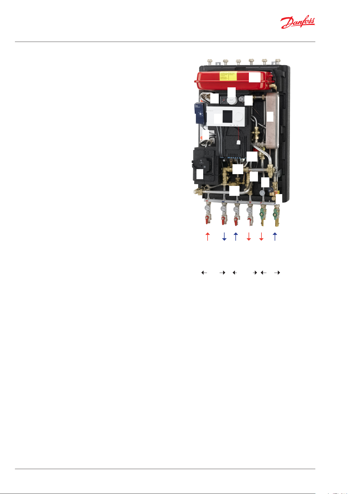
. MAIN COMPONENTS / CONNECTION
Akva Lux II VXi
1.
Plate heat exchanger HE
2.
Plate heat exchanger DHW
5.
Strainer
6.
Non-return valve
7A.
Ball valve ¾ ET/ET 120 mm for thermometer/manometer
7B.
Ball valve ¾ IT/ET 120 mm for thermometer
7C.
Ball valve ¾ ET/ET 120 mm for DVGW
8.
Circulation pump, HE
11.
Safety valve, HE
12.
Safety valve, DHW
13.
Thermometer
15.
Manometer
16.
Expansion vessel
23A.
Sensor pocket ½”/10x1, plug M10 for heat meter
23B.
Plugs ½” with O-Ring
24.
Fitting piece for heat meter ¾” x 110 mm
25.
Danfoss Controller ECL 310/A337
26.
Pressure independent control valve with integrated flow
38.
limiter AVQM
PTC2+P Controller
40.
Thermostat for bypass/circulation
57.
Safety thermostat Jumo AT
Accessories available as extra equipment (mounting on site)
Recirculation pipe set - Code No. 145H3879
For systems that feature domestic hot water recirculation.
KFE tap - code No. 145H3717
For filling and draining 1/4”
57
23A+B
15
1
8
13
40
25
24
19
7A 7B
16
38
2
26
11
12
6
7C
DH supply
Primary
HE return
DH return
Secundary DHW
HE supply
DHW
DCW
6 | © Danfoss | Produced by Danfoss Redan A/S | 2017.01
VI.JV.R1.02
Page 7
Instructions for installation and use Akva Lux II VXi, VXi Solo HWP, VXi Solo H
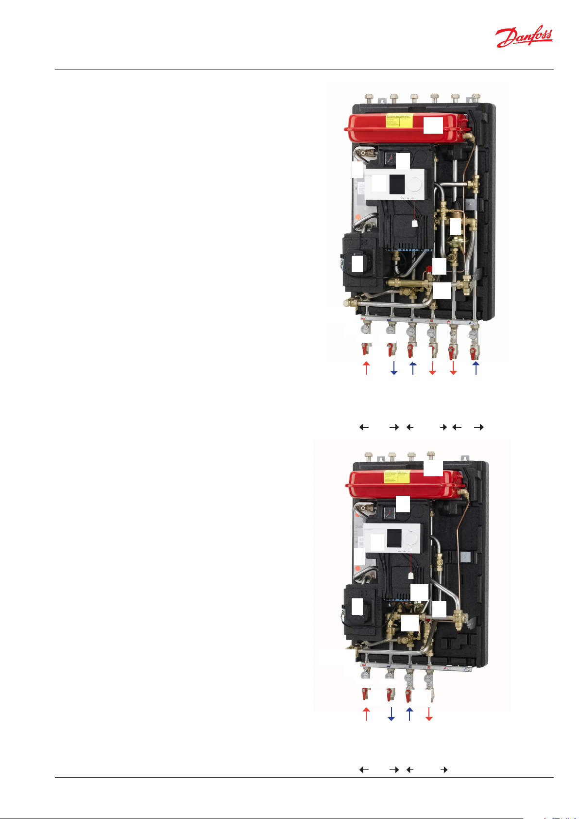
VXi Solo HWP
1.
Plate heat exchanger HE
4.
Differential pressure controller with flow limitation AVPB-F
5.
Strainer
7A
Ball valve ¾ ET/ET 120 mm for thermometer/manometer
7B
Ball valve ¾ IT/ET 120 mm for thermometer
8.
Circulation pump, HE
11.
Safety valve, HE
13.
Thermometer
14.
Pressure relief
15.
Manometer
16.
Expansion vessel
23A.
Sensor pocket ½”/10x1, plug M10 for heat meter
23B.
Plug ½” with O-ring
24.
Fitting piece for heat meter ¾” x 110 mm
25.
Danfoss Controller ECL 310/A337
Accessories available as extra equipment (mounting on site)
KFE tap - code No. 145H3717
For filling and draining 1/4”
1
15
25
8
16
23A+B
13
14
14
7A7B
4
11
24
VXi Solo H
1.
Plate heat exchanger HE
5.
Strainer
7A.
Ball valve ¾ ET/ET 120 mm for thermometer/manometer
7B.
Ball valve ¾ IT/ET 120 mm for thermometer
8.
Circulation pump, HE
11.
Safety valve, HE
13.
Thermometer
14.
Pressure relief
15.
Manometer
16.
Expansion vessel
23A.
Sensor pocket ½”/10x1, plug M10 for heat meter
23B.
Plug ½” with O-ring
24.
Fitting piece for heat meter ¾” x 110 mm
25.
Danfoss Controller ECL 310/A230
30.
Pressure independent control valve with integrated flow
limiter Danfoss AVQM
Accessories available as extra equipment (mounting on site)
KFE tap - code No. 145H3717
For filling and draining 1/4”
23A+B
1
8
13
DH return
DH supply
Primary
15
25
30
24
1414
7A 7B
HE return
HE supply
Cylinder supply
Secundary DHW
16
11
Cylinder return
VI.JV.R1.02
HE return
DH return
DH supply
Primary
© Danfoss | Produced by Danfoss Redan A/S | 2017.01 | 7
HE Supply
Secundary
Page 8
Instructions for installation and use Akva Lux II VXi, VXi Solo HWP, VXi Solo H
POS.
10 2
11 1 004U8616
12 1
13 1
14 1
15 2
16 1
17 3
18 1
19 1
20 3
21 3
22 1
23 1
24 2
25 1
26 1
27 7
28 3
29 1
30 2
31 1
32 1
33 64
34 2
35 4
36 1
37 1
38 1
39 1
40 2
41 5
42 2
43 1
44 1
45 1
46 1
47 1
48 1
49 1
Danfoss Standard
A3
1:7.5
Material
Size
Scale
Projection
Replace
Designation
E
D
C
B
A
87
6
5
4
3
2
kg
Weight
General tolerance accuracy
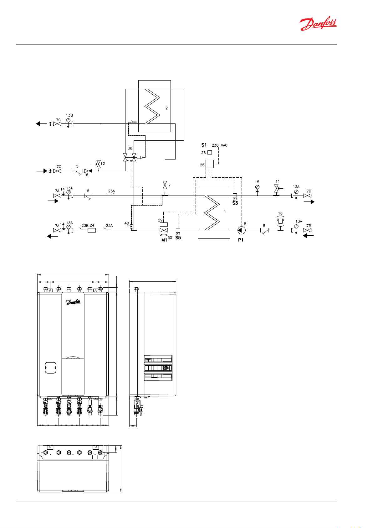
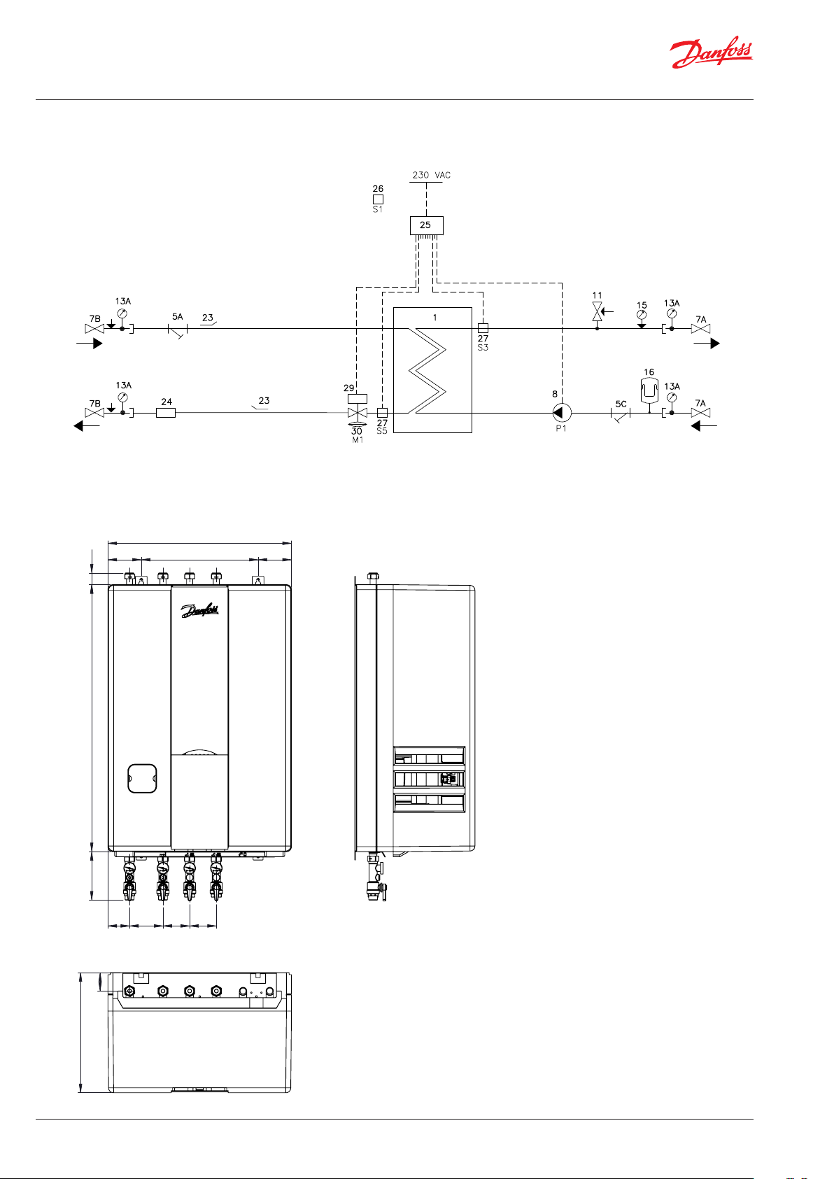
. DIAGRAMS, DIMENSIONAL SKETCHES, EXAMPLES AKVA LUX II VXI
DHW
DCW
HE
Supply
HE
Return
Circ.
Bypass
1 Plate heat exchanger HE
2 Plate heat exchanger DHW
5 Strainer
6 Non-return valve
7A Ball valve ¾ ET/ET, 120 mm
for Therm./Mano.
7B Ball valve ¾ IT/IT, for therm.
7C Ball valve ¾ ET/ET, DVGW
8 Circulation pump
11 Safety valve HE
12 Safety valve DHW
13 Thermometer
15 Manometer
16 Expansion vessel 12 L
23A Sensor pocket ½”/10x1, plug M10
for heat meter
23B Plug ½” with O-ring
24 Fitting piece for heat meter
3/4” x 110 mm
25 Danfoss Controller ECL 310/A337
26 Outdoor sensor, ESMT
27 Danfoss sensor, ESMC
29 Danfoss actuator HE, AMV 150
30 Pressure independent control
valve with integrated flow limiter
AVQM
38 PTC2+P controller
40 Thermostat for Bypass/
Circulation
HE
Supply
HE
Return
550
100 100 350
35 800
145
65 100 80 80 80 80 65
55
1 2 3 456
Wand
55
360
von oben
8 | © Danfoss | Produced by Danfoss Redan A/S | 2017.01
360
Connections:
1. District heating (DH) supply
2. District heating (DH) return
3. Heating (HE) return
4. Heating (HE) supply
5. Domestic hot water (DHW)
6. Domestic kold water (DCW)
VI.JV.R1.02
Page 9
Instructions for installation and use Akva Lux II VXi, VXi Solo HWP, VXi Solo H
POS.
Qty.
11
21
31
41
51
62
72
82
91
10 2
11 1 004U8616
12 1
13 1
14 1
15 2
16 1
17 3
18 1
19 1
20 3
21 3
22 1
23 1
24 2
25 1
26 1
27 7
28 3
29 1
30 2
31 1
32 1
33 64
34 2
35 4
36 1
37 1
38 1
39 1
40 2
41 5
42 2
43 1
44 1
45 1
46 1
47 1
48 1
49 1
50 1
Danfoss Standard
A3
1:7.5
Material
Size
Scale
Projection
Design
Replace
VX
Designation
E
D
C
B
A
87
6
5
4
3
2
kg
Weight
General tolerance accuracy
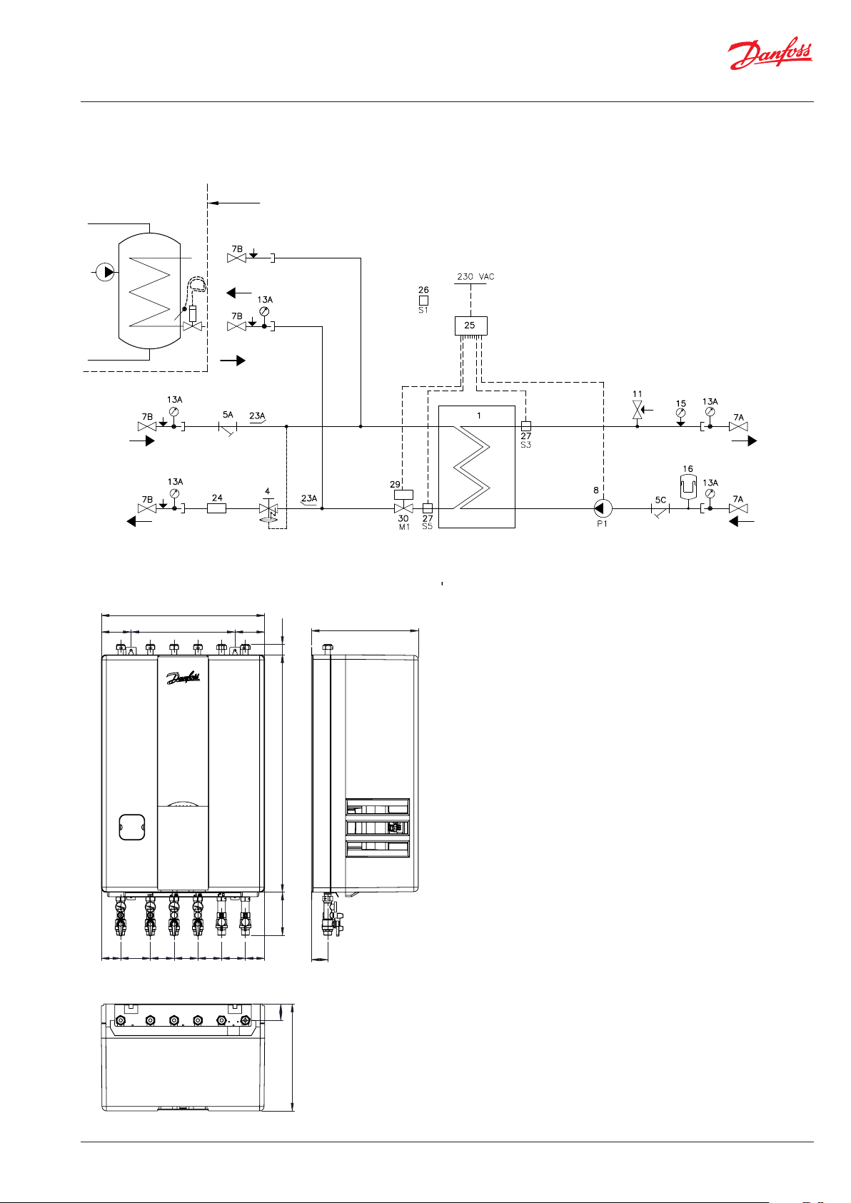
. DIAGRAM, DIMENSIONAL SKETCHES, EXAMPLES VXI SOLO HWP
Cylinder
DH
Supply
DH
Return
Supply limit
Cylinder supply
Cylinder return
1 Plate heat exchanger HE
4 Differential pressure controller with
flow limitation AVPB-F
5 Strainer
7A Ball valve ¾ ET/ET, 120 mm
for thermometer/manometer
7B Ball valve ¾ IT/IT, for thermometer
8 Circulation pump
11 Safety valve HE, 3 bar ½”
13 Thermometer
15 Manometer
16 Expansion vessel 12 L
23 Sensor pocket ½”/10x1, plug
M10 for heat meter
24 Fitting piece for heat meter
3/4” x 110 mm
25 Danfoss Controller ECL 310/
A337
26 Outdoor sensor, ESMT
27 Danfoss sensor, ESMC
29 Danfoss actuator HE, AMV 150
HE
Supply
HE
Return
550
100 100 350
65 100 80 80 80 80 65
1 2 3 456
von oben
VI.JV.R1.02
35 800
145
55
Wand
360
55
360
Connections:
1. District heating (DH) supply
2. District heating (DH) return
3. Heating (HE) return
4. Heating (HE) supply
5. Cylinder supply
6. Cylinder return
© Danfoss | Produced by Danfoss Redan A/S | 2017.01 | 9
Page 10
Instructions for installation and use Akva Lux II VXi, VXi Solo HWP, VXi Solo H
Danfoss Standard
A3
1:7.5
Material
Size
Scale
Projection
Designation
6
5
4
3
2
1
kg
Weight
General tolerance accuracy
. DIAGRAM, DIMENSIONAL SKETCHES, EXAMPLES VXI SOLO H
1 Plate heat exchanger HE
5 Strainer
7A Ball valve ¾ ET/ET, 120 mm for thermo./Mano.
7B Ball valve ¾ IT/IT, for thermometer
8 Circulation pump
11 Safety valve HE, 3 bar ½”
13 Thermometer
15 Manometer
16 Expansion vessel 12 L
DH
Supply
DH
Return
550
100 350 100
35 800
23 Sensor pocket ½”/10x1, plug M10 for heat
meter
24 Fitting piece for heat meter
3/4” x 110 mm
25 Danfoss Controller ECL 310/A230
26 Outdoor sensor, ESMT
27 Danfoss sensor, ESMC
29 Danfoss actuator HE, AMV 150
30 Pressure independent control valve with
integrated flow limiter Danfoss AVQM
HE
Supply
HE
Return
Connections:
1. District heating (DH) supply
2. District heating (DH) return
3. Heating (HE) return
4. Heating (HE) supply
145
65 100 80 80
1 234
55
Wand
360
von oben
10 | © Danfoss | Produced by Danfoss Redan A/S | 2017.01
VI.JV.R1.02
Page 11

Instructions for installation and use Akva Lux II VXi, VXi Solo HWP, VXi Solo H
. GENERAL, MOUNTING OF HEAT METER AND SAFETY VALVES
General
The installation, connection and maintenance of the substation
must be performed by qualified and authorised personnel.
Installation must always be performed in accordance with the applicable legislation and in compliance with these instructions.
The substation must be installed so that it is freely accessible and can
be maintained without unnecessary disruption. Lift the substation
by its mounting plate/rear section and secure it to a solid wall using
2 sturdy bolts, screws or expansion bolts positioned in the two keyholes in the mounting plate/rear section.
Before commissioning, rinse all the pipes in the household piping
system thoroughly to remove any impurities, and check and clean
the dirt strainers in the substation.
Connect the substation to the household piping in accordance with
the labelling at the bottom and/or in accordance with the instructions in this manual.
For fully insulated systems
The insulation front panel on the VXi substations can be removed
without using tools. Take hold of the air duct in the top and bottom
of the front insulation section and pull carefully forward until the
front insulation section releases from the rear section. Then pull
gently until the front section is free from the components.
Test and connections
Before filling the system with water, retighten all the pipe connections
because vibrations and shocks during transport and handling
may have caused leaks. Once the system has been filled with water,
tighten all the pipe connections once more before performing pressure test for leaks. After heating of the system, check all the connections and retighten if necessary.
Please note that the connections may feature EPDM rubber gaskets!
Therefore, it is important that you DO NOT OVERTIGHTEN the
union nuts. Overtightening may result in leaks. Leaks caused by
overtightening or failure to retighten connections are not covered
by the warranty.
Heat meter, fitting pieces.
The substation is equipped with fitting pieces for heat meter on
the district heating return line.
Fitting of heat meters
- Close the four ball valves on the district heating and the
heating sides.
- Loosen the union nuts at both ends of the fitting piece (A + B)
and remove it.
- Fit the heat meter, - remember to insert gaskets.
- Mount sensor, - remember to insert gaskets.
- After mounting of heat meter remember to check and tighten
all pipe connections before commissioning the substation.
(Measurement: 3/4” x 110 mm).
A B
Safety valve(s)
Always lead the blow-off pipe from the safety valve to a drain in
accordance with applicable legislation.
The insulation cover is be prepared for this and blow-off pipe
from the safety valves are led through the slit in the insulating
cover as shown in the photo to the right.
VI.JV.R1.02
© Danfoss | Produced by Danfoss Redan A/S | 2017.01 | 11
Page 12

Instructions for installation and use Akva Lux II VXi, VXi Solo HWP, VXi Solo H
. FILLING THE SYSTEM WITH WATER
Test and connections
Before filling the system with water, retighten all the pipe connections because vibrations and shocks during transport and handling
may have caused leaks. Once the system has been filled with water, tighten all the pipe connections once more before performing
pressure test for leaks. After heating of the system, check all the
connections and retighten if necessary.
Please note that the connections feature EPDM rubber gaskets!
Therefore, it is important that you DO NOT OVERTIGHTEN the union
nuts. Over-tightening may result in leaks. Leaks caused by overtightening or failure to retighten connections are not covered by
the warranty.
Filling, start-up
Before filling the system with water, retighten all the pipe connections. Once the system has been filled with water, tighten all the
pipe connections once more before performing pressure test for
leaks. Before filling the system with water and starting-up, check if:
- pipes are connected according to the circuit diagram,
- expansion vessel is connected,
- heat meter is mounted,
- shut-off valves are closed,
- threaded and flanged connections are tightened,
- recirculation, if any, has been established.
Filling the heat exchanger / the system with water:
• The pump must be switched off when filling the system with
water.
• Open the ball valves for the HE supply and return flow and
fill the system with water and at the same time venting the
system.
• Fill the heat exchanger / the system with water until the manometer shows a working pressure, which corresponds to the
system height + approx. 5 m (approx. 1.2 - 1.5 bar).
• Finally open the remaining ball valves and heat up the system.
• After filling and heat-up of the system it should be vented by
means of the air vents on the substation, if any and on the
radiators.
• Then switch on the pump.
* Note: There is no filling valve inside the station. For refilling use
a refill hose, customary for heating systems. Filling of water to
the heating system must be done outside the substation,
typically by connection to a cold water supply in the household installation.
Accessories available as extra equipment (mounting on site)
KFE tap - code No. 145H3717
For filling and emptying 1/4”
12 | © Danfoss | Produced by Danfoss Redan A/S | 2017.01
VI.JV.R1.02
Page 13

Instructions for installation and use Akva Lux II VXi, VXi Solo HWP, VXi Solo H
. VARIABLE CONNECTION POSSIBILITIES
Variable connections possibilities
The VXi substations offer variable connection possibilities, as connections of pipes can be established in the top or in the bottom of
the substation.
These variable connection possibilities makes it possible to establish
some of the connections in the top and others in the bottom of the
substation. This may be desirable in some cases.
Upon delivery the substation is prepared for connction in bottom of
the substation. Please note that the ball valves are supplied loose
and must be mounted on site.
To change the connection from the bottom to the top, demount the
plugs on the connection pipes in the top of the station before installing the ball valves and install the plugss in the connection pipes at
the bottom of the station.
PLEASE NOTE!
Remember to use gaskets when establishing connection in top of
unit.
Heating (HE)
The unit can be connected with piping both up and down on the heating side. Remove the plugs in top of unit, and establish connection
upwards. Mount the plugs in bottom connection pipes.
To change the connection from the bottom to the top, demount the
plugs on the connection pipes in the top of the station before installing the ball valves and install the plugss in the connection pipes at
the bottom of the station.
B
C
DCW
If there is a need for a DCW outlet in top of the unit, remove the blind
plate in pos. A and demount the plug on the DCW pipe in top of the
unit.
For DCW inlet in top of the unit, remove the plug in top of the unit and
the blind plate in pos. A. Mount the ball valve in top and use the plug
for plugging in the bottom (remember gaskets).
DHW
For DHW outlet in top of the unit, remove the blind plate and gasket
in Pos. B and relocate to Pos. C - see photos to the right.
The blind plate should be installed in Pos. C to prevent a pocket of
standing water that at worst can produce dangerous bacteria. Therefore, it is extremely important to install the blind plate as shown.
Also move the plug from the top connection to the DHW outlet in
the bottom of the unit and mount the ball valve in top (remember
gaskets).
DHW both up and down
The unit can be connected with piping both up and down for the domestic hot water. Remove blind plate in pos. B and plug in top of unit.
A
DHW outlet in top of unit
B
C
VI.JV.R1.02
© Danfoss | Produced by Danfoss Redan A/S | 2017.01 | 13
Page 14

Instructions for installation and use Akva Lux II VXi, VXi Solo HWP, VXi Solo H
. RECIRCULATION ONLY AKVA LUX II VXI
Circulation set for Akva Lux II VXi substations is available as extra equipment. The set applies to various substation types, therefore excess
components may occur.
It is to be recommended to prepare the substation for recirculation BEFORE mounting it on the wall.
Fig. 1
Circulation set:
1. Sheathed steel hose
2. Capillary tube with fittings
3. Mounting bracket
4. Hexagon nipple
5. Screw plug (4 mm)
Fig. 2
Remove console (6) incl. ECL controller and meter (not shown in
photo) to make room for mounting the circulation kit. The console
is removed by pulling it out / up so that it comes free of bypass
thermostat, manometer and domestic hot water controller. (See
also page 5).
2
5
1
6
Fig. 2
Fig. 3
Remove the nipples/plugs from the domestic hot water controller
(use a 6 mm Allen key). Do not re-use the plugs!
Fig. 4
Remove the existing capillary tube between the bypass thermostat
and the T-piece (marked with yellow). Use a 4 mm plug (5) to seal off
the T-piece.
Fig. 5
Fit/screw circulation hose end (steel hose) onto the controller (in the
rear connection piece). Fit a new capillary tube (2) between the controller and the bypass thermostat.
Fig. 6 + 7
Carry the circulation hose behind and down alongside the cold water
pipe as shown.
Fig. 8
Mount the supplied bracket, as shown, with two screws and secure
the hose with a 1½ “hexagonal nipple - thus prepared for establishing
a possible circulation connection.
Fig. 9
Alternatively, connect the circulation hose at the top of the station.
Cut an opening for the hose in the insulation cover. Mount the bracket
as shown with two screws and secure the hose as described above.
For fully insulated systems, it is always necessary to cut an opening
into the front cover for the DHW circulation.
Fig. 1
Fig. 4
3
4
Fig. 3
Fig. 5
NOTE!
Remember always to mount circulation pump and non-return
valve on the circulation pipe and to mount safety valve on the
DCW inlet. The pump must be installed so that the pump is pumping water towards the water heater.
This not part of the circulation set.
New function (from bypass to circulation thermostat)
When the substation is connected to the household recirculation
system, the thermostat will function as a circulation thermostat and
control the circulation water temperature, independently of the set
DHW temperature. It is recommended to set the termostat in pos. 3.
14 | © Danfoss | Produced by Danfoss Redan A/S | 2017.01
Fig. 6
Fig. 8
Fig. 7
T
Abb. 9Abb. 8
Fig. 9
VI.JV.R1.02
Page 15

Instructions for installation and use Akva Lux II VXi, VXi Solo HWP, VXi Solo H
. ELECTRICAL CONNECTION
Electrical connection
The electrical connection of the substation must be performed by
a qualified and authorised electrician in compliance with all applicable rules and regulations.
The station should be connected to a 230 V AC power supply.
The power supply / connection must be carried out in accordance
with the applicable regulations and instructions.
The station must be wired and connected to an external main switch
so that it can be disconnected during maintenance, cleaning and
repairs or in the event of an emergency.
Do not forget to establish potential equalization.
The Akva Lux II VXi and VXi Solo are delivered with Danfoss ECL
Comfort 210 or 310 controllers from factory.
The actuator and sensors are mounted in the station. The controller
is built into the console at the top of the station.
The station is wired and tested in the factory.
Electrical connections between the controller, pump(s), sensor and
actuator(s) are made.
Mounting of outdoor temperature sensor (ESMT)
The outdoor temperature sensor is delivered separately and must
be mounted on site according to the enclosed illustrations.
Controller ECL Comfort 210/310
Supply voltage: 230 V a.c. - 50 Hz
Voltage range: 207 bis 244 V a.c. (IEC 60038)
Power consumption: 5 VA
Load on relay outputs: 4(2) A - 230 V a.c
Load on triac outputs: 0,2 A - 230 V a.c.
Actuator AMV13 / AMV 150
Supply voltage: 230 V a.c. - 50 Hz
Power consumption: 2 / 8 VA
For further information please see enclosed instruction manual.
Pumpe UPM3 AUTO L
Supply voltage: 230 V a.c. - 50 Hz
Protection class:
IP44 Power consumption: Max. 52 Watt
For further information please refer to the enclosed instructions for
the circulation pumps.
The outdoor sensor is always to be mounted on the coldest side
of the property, where it is less likely o exposed to direct sunshine
(normally the north side of the property).
The sensor must not be exposed to the morning sun, and should
not be placed above windows, doors, air vents or other heat sources,
and not under balconies and roof eaves.
Mounting height approx. 2.5 m above ground.
Temperature range: -50 to 50° C.
Electrical connections
The cables can be connected to the sensor in any order.
Connection cable: 2 x 0.4 - 1.5 mm²
For ECL 210 / 310:
Connect the cable ends to ECL controller in common ground
terminal and in terminal 29.
Access to ECL base part
Access to the base part for connection of outdoor sensor or the like
is obtained by pulling the lock (pin) down with a screwdriver until
a yellow line is visible on the lock. Then, the front piece can easily
be removed. Lock by pressing the lock (pin) up.
Lock / pin
VI.JV.R1.02
ECL Comfort 210 bundpart
© Danfoss | Produced by Danfoss Redan A/S | 2017.01 | 15
Common ground
terminal
Page 16

Instructions for installation and use Akva Lux II VXi, VXi Solo HWP, VXi Solo H
73695220 DH-SMT/SICO 02 / 2006 VI.DB.O1.8H 1
. ADJUSTMENT AND COMMISSIONING
General information
PLEASE NOTE! Some models may have a slightly different appearance, but the control function is in principle the same as described
below.
Commissioning
Commission the substation in accordance with the instructions
on pages 3-12.
Filling the system / operating pressure
Fill the unit with water according to the instructions on page 9.
If the pressure drops below 1 bar, water must be added to the system.
The operating pressure should never exceed 1.5 bar.
(The safety valve opens at 2,5 bar)
If system pressure drops dramatically within a short time, heating
system should be examined for leakage, - this includes checking
the factory set pressure of the expansion vessel, which is normally
0,5 bar.
Differential pressure controller (VXi Solo HWP)
The self-acting differential pressure controller with flow limitation
primarily reduces the high flunctuations in pressure in the district
heating network, ensuring constant operating pressure across the
substation and thereby ensures the best possible operating conditions for radiator thermostats, which enables individual control of
the room temperature. The controller closes on rising differential
pressure or when set max. flow is exceeded.
Control valve closes on rising differential pressure and opens on falling differential pressure to maintain constant differential pressure.
The differential pressure is preset from factory and should not be
adjusted afterwards
The controller has a control valve with adjustable flow restrictor,
and the flow setting is being done by the adjustment of the flow
restrictor position. The adjustment can be performed on the basis
of flow adjustment diagram (see relevant instructions).
The controller is equipped with excess pressure safety valve, which
protects control diaphragm from too high differential pressure.
See enclosed instruction manual,
AVPB-F
Differential pressure controller (Akva Lux II VXi and VXi Solo H)
For Akva Lux II VXi and VXi Solo H, the differential pressure controller
is installed in the AVQM self-acting flow controller with integrated
control valve. Please see page 18.
Instructions
AVPB AVPB -F AVPB AVPB-F AVPB AVPB-F
(PN 16) ( PN 16) (PN25) (PN25) ( PN25) (PN25)
DN 15 - 32 DN 15 - 32 D N 15 - 50 DN 15 - 50 DN 32 - 50 DN 32 - 50
∆p = 0.05 - 0.5 ∆p = 0.2 ∆p = 0.2 - 1.0 ∆p = 0.5 ∆p = 0.2 - 1.0 ∆p = 0.5
∆p = 0.2 - 1.0 ∆p = 0.3 ∆p = 0.3 - 2.0 ∆p = 0.3 - 2. 0
∆p = 0.8 - 1.6 ∆p = 0.5
Differential pressure controller with flow limitation
ENGLISH
AVPB, AVPB-F, AVPBT, AVPBT-F
Differenstrykregulator med flowbegrænsning
DANSK
AVPB, AVPB-F, AVPBT, AVPBT-F
Differenzdruck-- (und Temperatur-) Regler mit
DEUTSCH
Durchflussbegrenzung AVPB, AVPB-F, AVPBT, AVPBT-
Regulador de presión diferencial con limitación de
ESPAÑOL
caudal AVPB, AVPB-F, AVPBT, AVPBT-F
Drukverschil- (en temperatuur-) regelaar met
NEDERLANDS
debietbegrenzing AVPB, AVPB-F, AVPBT, AVPBT-F
Adjustment of the flow volume
Flow setting is being done by the adjustment of
the flow restrictor position.
AVPB, AVPB-F, AVPBT, AVPBT-F – PN 16,25/DN 15 – 50
AVPBT-F AVT/AVPBT-F AVPBT AVT/AVPBT
(PN25) (PN25) (PN25) (PN25)
DN 15 - 25 DN 32 - 50 DN 15 - 25 DN 32 - 50 DN 15 - 25 DN 32 - 50 DN 15 - 25 DN 32 - 50
∆p = 0.5 ∆p = 0.5 ∆p = 0.5 ∆p = 0.5 ∆p = 0.2 - 1.0 ∆p = 0.2 - 1.0 ∆p = 0.2 - 1.0 ∆p = 0.2 - 1.0
Page 2
Regulator diferenčnega tlaka in omejevalnik
SLOVENŠČINA
www.danfoss.com
pretoka AVPB, AVPB-F, AVPBT, AVPBT-F
Side 2
Nyomáskülönbség-szabályozó és térfogatáram
MAGYAR
www.danfoss.dk
korlátozó AVPB, AVPB-F, AVPBT, AVPBT-F
Regulátor diferenčního tlaku s omezovačem
Seite 2
ČESKY
www.danfoss.de
www.danfoss.es
www.danfoss.com
průtoku AVPB, AVPB-F, AVPBT, AVPBT-F
Page 2
Regulator różnicy ciśnień z ograniczeniem
POLSKI
przepływu AVPB, AVPB-F, AVPBT, AVPBT-F
Blz. 2
Регулятор перепада давлений с ручным
РУССКИЙ
ограничением расхода AVPB, AVPB-F, AVPBT, AVPBT-F
F
www.danfoss.com
www.danfoss.hu
www.danfoss.com
www.danfoss.pl
www.danfoss.com
Stran 20
20. oldal
Strana 20
Strona 20
Стр. 20
16 | © Danfoss | Produced by Danfoss Redan A/S | 2017.01
VI.JV.R1.02
Page 17

Instructions for installation and use Akva Lux II VXi, VXi Solo HWP, VXi Solo H
. HEATING CIRCUIT, DANFOSS ECL / AUTOMATICS
Weather-compensated control of the heating circuit
Danfoss ECL 210 / ECL 310
The temperature for the heating circuit is controlled electronically by
the Danfoss ECL controller. The supply temperature ist calculated by
the controller on basis of the outdoor temperature.
The ECL Comfort controller is loaded with a selected application by
means of an ECL Application Key (Plug-&-Play). The Application Key
contains information about application, languages and factory settings. Various applications can be loaded by means of the ECL Application Key, and it is possible to update the controller with new
application software.
The controller is factory preset to turn off the heating automatically
in the summer period. The controller settings can be changed in accordance with the enclosed producer instructions for the mounted
controller.
Turn the dial to choose ’MENU’
and press to confirm selection
The controller is pre-programmed (normally) with the following factory settings:
• Language = English,
• Operating mode of the controller = Comfort “Sun” Symbol,
• Application type = A337 (Akva Lux II VXi, VXi Solo HWP)
• Application type = A230 (VXi Solo H),
Motor speed and motor protection is set and the controller is functional is functionally tested, so it’s ready for use.
Start-up of ECL 210 / 310 (easy start-up)
When the outside temperature sensor is properly installed and electrically connected to the controller as described in the instructions on
page 15, proceed as follows:
1. Connect the controller and switch it on,
2. Choose ‘MENU’ in any circuit - Confirm and turn the dial and
choose ‘Common controller settings’ in the circuit selector at the
top right corner in the display,
(You navigate in the controller by turning the dial left or right to the desired position.
The position indicator in the display ( ) will always show you where you are).
3. Turn dial to select time and date,
Push the dial to confirm the selection
4. Select time and date,
5. The controller is now ready for use. Set heat curve and
temp. max. according to the procedure described below.
Setting / change of factory settings:
6. Choose ‘MENU’ in any circuit - Confirm and turn the dial and
choose ‘ Heating circuit’ in the circuit selector at the top right corner
in the display (radiator symbol),
7. Then turn the diall and choose ‘Settings’ and confirm by pushing
the dial. Then choose ‘Flow temperature’ and here you set ‘Heat
curve’ (value), according to the actual system type, including “Temp.
max.”,
8. Typical setting ranges:
Circuit selector
Choose this symbol to enter
‘Common controller settings”
Circuit selector
Heating circuit
Heating circuit one-string two-string Floor heating
Temp. max. 70-90°C 55-65°C 35-40°C
Heat curve 1,0 - 1,75 0,8 - 1,0 0,1 - 0,5
Note; in systems that feature only floor heating the max. supply temperature must be changed according to the above mentioned information.
If increased heat demand occurs during the heating period, the controller
settings can be changed
See ECL Application Key Box with ECL Comfort
210/310 user guide and mounting guide, for
further information.
VI.JV.R1.02
© Danfoss | Produced by Danfoss Redan A/S | 2017.01 | 17
Page 18

Instructions for installation and use Akva Lux II VXi, VXi Solo HWP, VXi Solo H
. CONTROL OF HEATING CIRCUIT
Self-acting flow controller with integrated control valve and ac
tuator Akva Lux II VXi & VXi Solo H
For controlling the heating circuit the Akva Lux II VXi and VXi Solo H
are supplied with a self-acting flow controller with integrated control valve Danfoss AVQM and a Danfoss AMV actuator placed in the
primary return flow line. The AMV actuator is electrically wired to the
controller from the plant.
The control valve closes on rising differential pressure and opens on
falling differential pressure to control max flow. The controller closes
when set max. flow is exceeded.
In a combination with electrical actuators AMV and ECL electronic
controllers the flow and temperature can be controlled to achieve
highest energy savings. The controller is equipped with excess pressure safety valve, which protects control diaphragm for flow control
from too high differential pressure.
AMV 150
The actuator has undergone a functional test and is preset from
factory.
In the event of operating disturbances the actuator can be shut off
manually by turning the manual override knob on top of the actuator
clockwise. Please note that the knob can be “tight” to turn.
AMV 13
The actuator has undergone a functional test and is preset from
factory.
Depending on the selected setting of the safety function, the AMV 13
valve is fully opened or closed when the voltage supply is switched
off.
-
AVQM AMV 13
AMV 150
Manual override
Press and hold the button (on
the bottom side of the actuator)
during manual operation.
For additional information see the enclosed manuals:
Self-acting flow controller with integrated control valve and
actuator AVQM
Electronic actuator AMV 150
Electronic actuator AMV 13.
18 | © Danfoss | Produced by Danfoss Redan A/S | 2017.01
VI.JV.R1.02
Page 19

Instructions for installation and use Akva Lux II VXi, VXi Solo HWP, VXi Solo H
Actuator and valve, VXi Solo HWP
For controlling the heating circuit the VX Solo II HWP is supplied with
a Danfoss AMV 150 or AMV 13 actuator and a Danfoss valve VS 2,
placed on the primary return flow line. THE AMV actuator is electrically wired to the controller from factory.
The actuator has undergone a functional test and is preset from
factory.
In the event of operating disturbances the actuator can be shut off
manually by turning the manual override knob on top of the actuator
clockwise. Please note that the knob can be “tight” to turn..
Depending on the selected setting of the safety function, the AMV 13
valve is fully opened or closed when the voltage supply is switched
off.
For additional information see the enclosed manuals for:
Electronic Actuator AMV 150
Danfoss Valve VS 2
VS 2
AMV 150
Manual override
Press and hold the button (on
the bottom side of the actuator)
during manual operation.
AMV 13
Safety function, Jumo AT
The heating circuit(s) can be supplied with a safety thermostat Jumo
AT for protection against overheating.
From factory the Jumo AT safety thermostat is pre-wired to the
Danfoss ECL controller with a 2 m cable, enabling the thermostat
housing to be mounted in any mounting position on the household
piping (HE supply) on site.
For additional information see the enclosed manuals for:
Jumo AT
VI.JV.R1.02
© Danfoss | Produced by Danfoss Redan A/S | 2017.01 | 19
Page 20

Instructions for installation and use Akva Lux II VXi, VXi Solo HWP, VXi Solo H
. HEATING CIRCUIT, PUMP AND SUMMER OPERATION
Grundfos Pump UPM3 Auto L
Grundfos UPM3 Auto L has 10 optional settings, which can be
selected with the push-botton. See fig. 1 - User interface.
The user interface is designed with a single push button, one
red/green LED and four yellow LEDs.
The pump is set from factory to Proportional pressure curve 3.
The user interface shows:
* performance view (during operation)
- operation status
- alarm status
* settings view (after pressing the button)
The LEDs show the power consumption for the pump.
When the pump is running, LED 1 is green. The four yellow
LEDs indicate the current power consumption (P1).
See fig. 2 - Performance view.
Fig. 1. User interface
with a push button and
five LEDs.
Fig. 2. Performance view
Performance
% of P1 max.
0% (standby)
0 - 25%
25 - 50%
50 - 75%
75 - 100 %
Green Yellow Yellow Yellow Yellow
20 | © Danfoss | Produced by Danfoss Redan A/S | 2017.01
VI.JV.R1.02
Page 21

Instructions for installation and use Akva Lux II VXi, VXi Solo HWP, VXi Solo H
Check the pump setting by pressing the button once. The LEDs will
briefly show the pump setting before changing back to showing the
power consumption. See fig. 3 - Pump settings.
If the pump setting does not give the desired distribution of heat in
the rooms of the house, change the pump setting. See fig. 4 - Rec-
ommended pump settings.
To change the pump setting, choose the setting you want (see fig
3), press the button down for more than 2 seconds (less than 10)
and the LEDs will flash. Then press the button until the LEDs shows
the desired setting. The LEDs flash and when they stop the new
setting is saved. The LEDs return to show power cunstumption.
Please note that if the LEDs do not flash after 2 seconds, possibly
the pump setting is locked. To unlock, press the button down for
more than 10 seconds. LEDs will flash and the pump is unlocked.
To lock the pump, repeat the procedure.
Fig. 3. Pump settings
Fig. 4. Recommended pump settings
UMP3 15-70 AUTO
Application Recommended pump mode
Radiator
two-pipe system
Radiator
one-pipe system
Floor heating 1. Auto adapt, Constant pressure mode
1. Auto adapt proportional pressure mode
2. Proportional pressure mode
1. Constant curve mode, speed 1-2-3-4
2. Constant pressure mode
For more information, see enclosed Grundfos instructions.
grundfos INSTRUCTIONS
UPM3
AUTO L
1
In case the 1st LED is red the pump has detected one or more alarms.
See fig. 5 - Alarm status. When there is no active alarm anymore
the user interface switches back to operation mode shortly and then
showing power consumption.
VI.JV.R1.02
Ventilation 1. Constant curve mode, speed 1-2-3-4
2. Constant pressure mode
Domestic hot water* 1. Constant curve mode, speed 1-2-3-4
* Bronze or stainless steel pump housing
Fig. 5. Alarm status
Function Red Yellow Yellow Yellow Yellow
Blocked
Supply voltage low
Electrical error
© Danfoss | Produced by Danfoss Redan A/S | 2017.01 | 21
Page 22
Instructions for installation and use Akva Lux II VXi, VXi Solo HWP, VXi Solo H
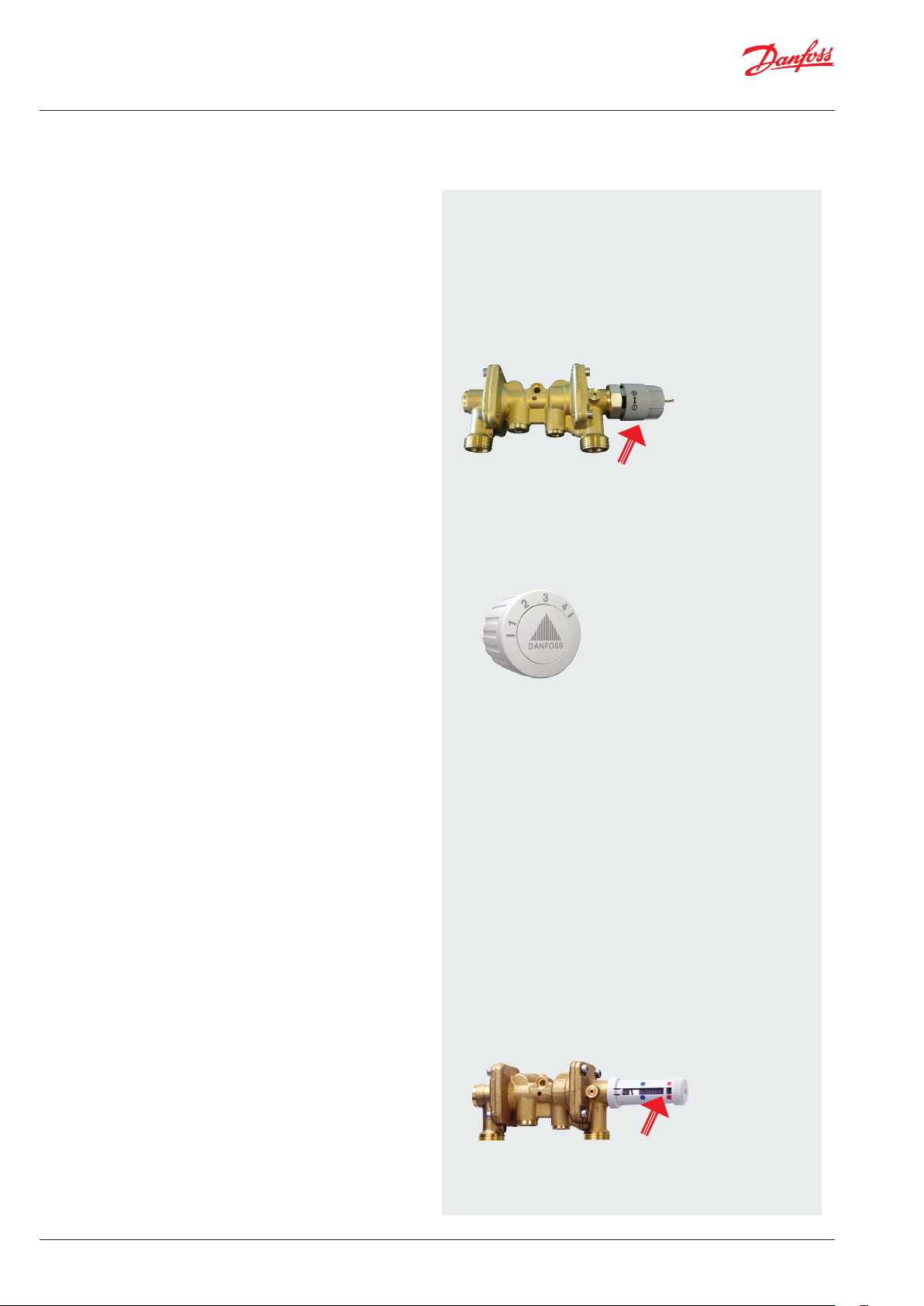
. Domestic hot water (Akva Lux II VXi)
General information
PLEASE NOTE! Some models may have a slightly different appearance,
but the control function is in principle the same as described below.
Commissioning
Commission the substation in accordance with the instructions
on pages 3-12.
Regulation of domestic hot water temperature
Akva Lux II VXi
The domestic hot water is prepared in the heat exchanger based on
the flow principle and the temperature is controlled by a combined
hydraulic and thermostatic self-acting controller PTC2+P with integrated differential pressure controller, which blocks the flow of
primary and secondary side flow through the heat exchanger immediately after completion of the tapping process.
Fig. 1
PTC2 controller for DHW (Fig. 1).
Adjust the hot water temperature by moving the adjuster lever towards “+” (hotter) or “-” (colder). Start by turning the lever clockwise
– until it stops/until you cannot turn it any further. Then turn the lever
counter-clockwise until the temperature of the tap water is approx.
48°C during normal tapping flow (7–8 litres per min.). The temperature
must never exceed 55°C to prevent limescale deposits building up
in the water heater.
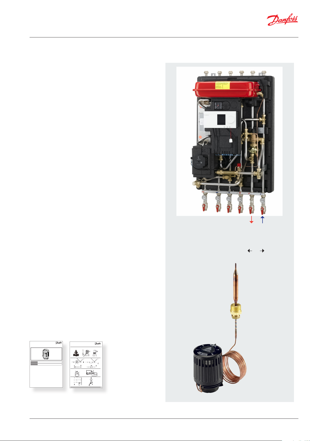
Bypass thermostat (default)
As a standard the substation is equipped with a bypass thermostat,
Danfoss FJVR, so that when water is tapped, the water heater
immediately starts to produce hot water. We recommend setting
of the thermostat in pos.3. If you have to wait a long time (i.e. more
than 20 sec.) for hot water, it may be necessary to set the thermostat
at a higher value.
If you want to avoid waiting time altogether, you will need to set up
domestic hot water recirculation to the tapping points.
Circulations thermostat / conversion to recirculation
If the household piping system features domestic hot water recirculation, the substation must be connected to the recirculation system.
Scale setting (indicative)
Pos. 2 = 30°C
3 = 40°C
4 = 45°C
Conversion to recirculation requires only an additional circulation
set. (This is not part of the delivery and must be purchased as extra
equipment, - see photo on page 14).
Abb.
Adjuster lever
Fig. 2
Connect the recirculation pipe from the fixed household piping system to the hexagon nipple at the bottom of the substation (please see
page 14 for instructions about how to make recirculation connection).
If a time-controlled pump is used, we recommend setting the circulation water temperature to approx. 35 °C.
Alternative controller PM2+P
As alternative the temperature can be controlled by a the pressure-controlled self-acting controller PM2+P with integrated differential pressure controller. Set the DHW temperature by turning the
adjuster lever towards red (hotter) or blue (colder). Start by turning
the lever clockwise - until the pin is opposite the blue dot. Then turn
the lever counter-clockwise until the temperature of the tap water
is approx. 48°C during normal tapping flow (7–8 litres per min.). The
temperature must never exceed 55°C to prevent limescale deposits
building up in the water heater. NB! The pin must be positioned between the blue and red dot, otherwise the controller will shut down.
22 | © Danfoss | Produced by Danfoss Redan A/S | 2017.01
Fig. 3
Adjuster lever
VI.JV.R1.02
Page 23
Instructions for installation and use Akva Lux II VXi, VXi Solo HWP, VXi Solo H
1
District Energy VI.52.V4.00 DEN -SMT/SI
. Domestic hot water (VXi Solo HWP)
General
The VXi Solo HWP is supplied with connection pipes for cylinder
on the primary side.
Please note that domestic hot water cylinder control is not included in the standard delivery.
VXi SOLO
Abb.
Temperature control of DHW cylinder
As an option, the VXi Solo HWP can be equipped with a RAVK
self-acting thermostat and a 2-way valve VMA for temperature
regulation of the DHW cylinder, - for installation outside the system.
The controller closes when the temperature rises.
Instructions
RAVK (25-65 °C)
RAVK www.danfoss.com Page 4
ENGLISH
RAVK www.danfoss.pl Strona 4
POLSKI
Installation Guide
VMA DN 15
VMA / RAVI / RAVK / RAVV VMA/ABVVMA
69
131
G ⁄A
65
139
Cylinder return
Cylinder supply
DHW
VI.JV.R1.02
© Danfoss | Produced by Danfoss Redan A/S | 2017.01 | 23
Page 24
Instructions for installation and use Akva Lux II VXi, VXi Solo HWP, VXi Solo H
. Maintenance
Maintenance work
Is only to be carried out by qualified and authorised personnel.
Inspection
The water heater should be checked regularly by authorised personnel. Any necessary maintenance must be performed in accordance
with the instructions in this manual and other sets of instructions.
During service the dirt strainers are to be cleaned – including the
filter on the controller, all pipe connections must be tightened and
the safety valve must be function tested by turning the lever.
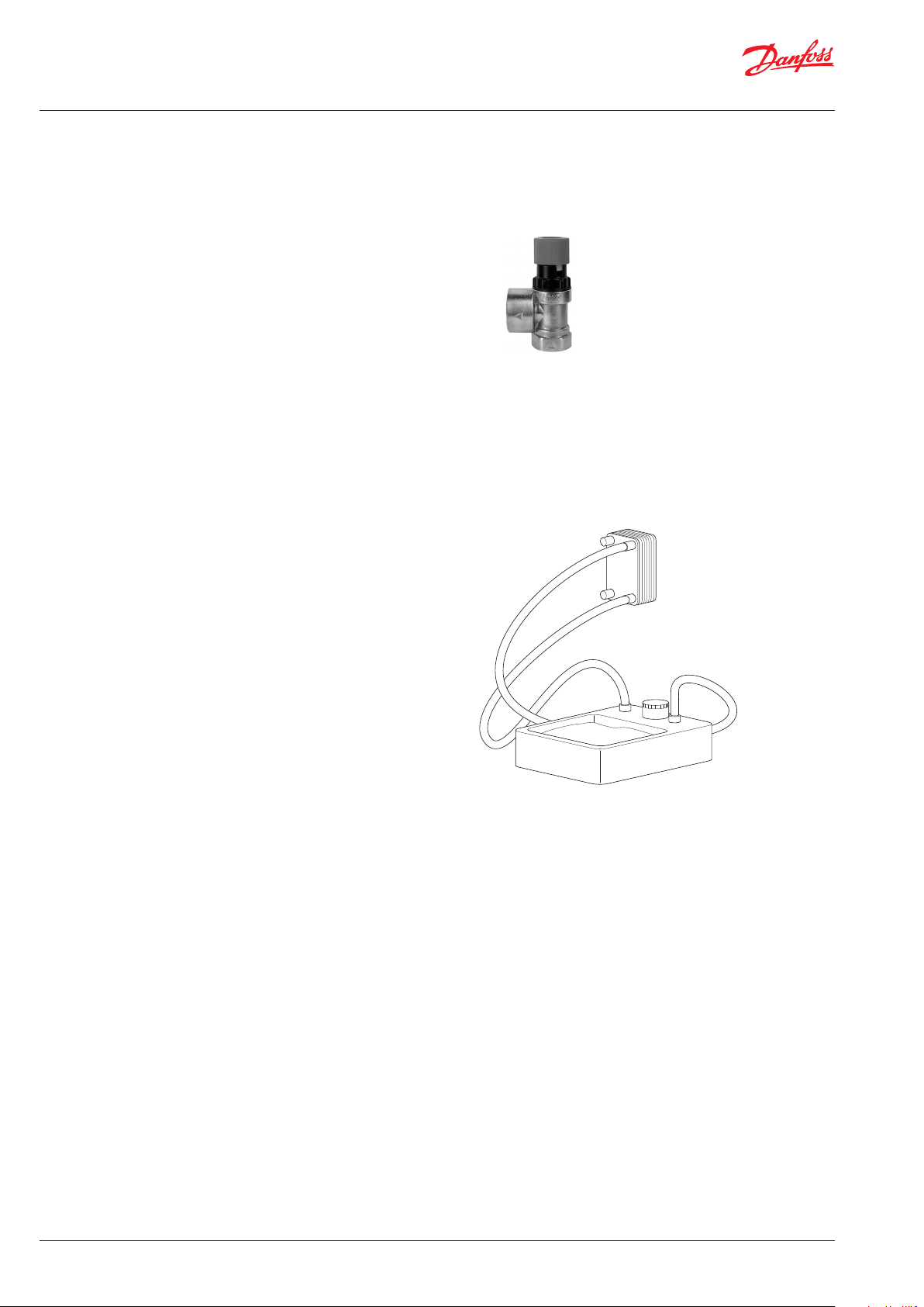
Rinsing/cleaning of plate heat exchanger
To clean the plate heat exchanger, rinse it by running clean water
through the exchanger at high speed and in the opposite direction
to the normal flow. This will remove any dirt deposits that may have
built up in the exchanger. If rinsing with clean water is not sufficient,
the exchanger can also be cleaned by circulating a cleaning agent
approved by Danfoss (e.g. Kaloxi or Radiner Fl cleaning fluid) through
the exchanger. Both these cleaning fluids are environmentally friendly
and can be disposed off through the standard sewer system. After
use of a cleaning fluid, the plate heat exchanger must be rinsed
thoroughly with clean water.
Acid cleaning of plate heat exchanger
Deposits of limescale may build up in plate heat exchangers for
domestic hot water on account of the large temperature fluctuations,
and because aerated water is used on the secondar y side. If it becomes
necessary to clean the exchanger with acid, this can be done as shown
on the drawing to the right. Brazed plate heat exchangers can
withstand rinsing with a dilute acid solution - e.g. 5% formic, acetic
or phosphoric acid).
Measures after maintenance work
After maintenance work and before commissioning:
– Check that all screwed connections are tight.
– Check that all safety features, covers, that were removed, have
been replaced properly.
– Clean the working area and remove any spilled materials.
– Clear all tools, materials and other equipment from the working
area.
– Connect to energy supply and check for leaks.
– Vent the system.
– Carry out any necessary adjustment again.
– Make sure that all safety features on the device and the system
work properly.
Meter reading
The caretaker/owner must perform visual checking and reading of
the district heating meter at short, regular intervals. (The meter is
not a part of the delivery from Danfoss).
Service procedures must only be performed by trained, authorised
personnel.
NB! Excessive consumption for whatever reason is not covered by
the Danfoss warranty.
Cooling / Return temperature reading
Cooling – i.e. the difference between the supply and return temperature of the district heating water – has a significant effect on overall
energy economy. Therefore, it is important to focus on the supply
and return temperature in the heating system. The difference should
typically be 30–35°C. Please note that a low district heating return
temperature is directly related to the return temperature from the
heating circuit and the return temperature of the circulation water.
It is therefore important to focus on these return temperatures.
24 | © Danfoss | Produced by Danfoss Redan A/S | 2017.01
VI.JV.R1.02
Page 25

Instructions for installation and use Akva Lux II VXi, VXi Solo HWP, VXi Solo H
. Maintenance schedule (recommendations)
Interval Maintenance work Comments
If you identify a leak, replace the gaskets and retighten the pipe connections
Check the functionality by turning the lever on the safety valves
In the event of irregularities, lack of functionality or visible faults and
defects in a component, replace the component in questionn
Visual check. Check whether it is possible to disconnect the current to the
substation.
Follow the instructions in the present manual
At least once a year
Check all connections for leaks
Check that the safety valve on the cold water supply is
functioning correctly.
Check that all components are intact and functioning as
intended
Clean all dirt filters/strainers in the substation Replace any filters that are not intact
Check that any electrical cables are in serviceable condition
and that it is possible to disconnect the electrical power supply to the substation
Check the pipes and exchanger for signs of corrosion Visual check
Check that the insulation cover is intact Make sure that the insulation cover encloses the substation tightly
Check that the temperature regulators are set in accordance
with the instructions in this manual
Check the functions of all shut-off valves Check that the ball valves open and close as they should
*)Enduser/caretaker.
Note! After maintenance work has been carried out all gaskets HAVE to be replaced.
VI.JV.R1.02
© Danfoss | Produced by Danfoss Redan A/S | 2017.01 | 25
Page 26

Instructions for installation and use Akva Lux II VXi, VXi Solo HWP, VXi Solo H
. TROUBLE SHOOTING HEATING
Fundamental
In the event of disruptions to operation, you should fundamentally - before commencing the actual troubleshooting - check
whether:
• the system is correctly connected
• the district heating supply temperature is at its normal level
• the differential pressure is at its normal level. Ask your district
heating supplier if necessary
Problem Possible cause Solution
• there is a power supply to the system - pump and automatics
• the dirt strainer in the district heating supply pipe is clean
• there is air in the system (if the system is vented)
No heat Dirt strainer in the district heating or
heating return line clogged.
Filter in district heating meter clogged.
Defective or incorrectly set differential
pressure controller.
Air pockets in the system.
Uneven distribution of heat Air pockets in the system. Vent the system thoroughly - see the
Poor cooling Insufficient heating surface / radiators
too small compared to the total heating
requirement of the building.
Poor utilisation of the existing heating
sursurface.
No heat Defective thermostat (sensor).
Defective actuator - or possibly dirt in
the valve housing.
Clean the filter/dirt strainer.
Cean the filter (in consultation with the
district heating plant).
Check the functions of the differential
pressure controller - if necessary, clean the
valve seat.
Vent the system thoroughly - see the
instructions.
instructions.
Increase total heating surface.
Turn on all radiators and prevent the
radiators in the system from becoming
warm at the bottom.
Replace sensor.
Check that the actor is functioning
correctly - clean the valve seat if necessary.
Automatic components/controller
incorrectly adjusted or defective - or
possibly power outage.
The pump is not working.
The pump is set at too low speed of
rotation (not all system types).
Air pockets in the system.
26 | © Danfoss | Produced by Danfoss Redan A/S | 2017.01
Check that the controller setting is correct
- see the separate instructions for the controller.
Check the power supply.
Temporarily set the actuator to “manual”
control - see the instructions for the heating system.
Check that there is a power supply for the
pump, and that it is operating.
Check that there is no air in the pump
housing - see pump manual.
Set the pump to a higher speed - see the
instructions for the heating system.
Vent the installation thoroughly - see the
instructions.
VI.JV.R1.02
Page 27

Instructions for installation and use Akva Lux II VXi, VXi Solo HWP, VXi Solo H
VI.JV.R1.02
© Danfoss | Produced by Danfoss Redan A/S | 2017.01 | 27
Page 28

Instructions for installation and use Akva Lux II VXi, VXi Solo HWP, VXi Solo H
. TROUBLE SHOOTING DOMESTIC HOT WATER
Fundamental
In the event of disruptions to operation, you should fundamentally - before commencing the actual troubleshooting - check
whether:
• the system is correctly connected
• the district heating supply temperature is at its normal level
• the differential pressure is at its normal level. Ask your district
heating supplier if necessary
Problem Possible cause Solution
• there is a power supply to the system - pump and automatics
• the dirt strainer in the district heating supply pipe is clean
• there is air in the system (if the system is vented)
DHW*, no hot water Non-return valve in the circulation pipe
defective (leads to mixing - the circulation water pipes become cold during
tapping).
Temperature too low / variations in
temperature
Lack of hot water pressure Clogged strainer in the cold water meter
Long wait for hot water Circulation pump out of order. Check whether the pump is running -
No hot water Dirt strainer in the district heating sup-
Non-return valve in thermostatic mixer
in the bathroom defective - results in hot
and cold water mixing. Please note that
fluctuating temperatures may occur at
other tapping points in the system!
NB, Check all mixers in the house for
faults/defects!
or possibly in the cold water supply in
the unit.
Calified heat exchanger.
ply line clogged.
Replace the non-return valve.
Replace the mixer or perhaps only the
non-return valve.
Clean the strainer (cold water meter,
in consultation with the water supply
company).
Replace the heat exchanger.
and whether there is a power supply to
the pump. Make sure that there is no air
in the pump housing.
Clean the dirt strainer.
Defective DHW controller.
Defective sensor. (PTC2)
Hot water temeprature too low As above.
Non-return valve in the circulation pipe
defective (leads to mixing - the circulation
water pipes become cold during ).
Hot water temperature too high Defective domestic hot water controller. Check the function of the DHW control-
Temperature falls during tapping (lack
of capacity)
28 | © Danfoss | Produced by Danfoss Redan A/S | 2017.01
Air in the capillary tube for the differential pressure controller.
Calified plate heat exchanger.
Check controller settings. You may contact Danfoss Redan A/S for further information.
Replace sensor.
As above.
Replace non-return valve.
ler and replace if defective.
Vent the capillary pipe.
Replace the plate heat exchanger.
VI.JV.R1.02
Page 29

Instructions for installation and use Akva Lux II VXi, VXi Solo HWP, VXi Solo H
Systems with DHW cylinder
Problem Possible cause Solution
Poor cooling Calified heat exchanger. Clean DHW cylinder with acid solution or
Temperature falls during tapping (lack
of capacity
Domestic hot water temperature too
high
No domestic hot water Calified heat exchanger.
The immersion sensor incorrectly fitted
in the cylinder.
Calified heat exchanger.
Defective immersion sensor. Replace immersion sensor.
Inadequate cylinder capacity.
replace heating element.
You may check the specifications of the
manufacturer conc. cylinder capacity.
Place sensor correctly in accordance with
the cylinder manufactur’s specifations.
You may contact Danfoss Redan A/S for
further information.
Clean DHW cylinder with acid solution or
replace heating element.
Clean DHW cylinder with acid solution or
replace heating element.
Wait for heating / loading of the cylinder.
You may check the specifications of the
manufacturer conc. cylinder capacity.
VI.JV.R1.02
© Danfoss | Produced by Danfoss Redan A/S | 2017.01 | 29
Page 30

Instructions for installation and use Akva Lux II VXi, VXi Solo HWP, VXi Solo H
. EU DECLARATION OF CONFORMITY
30 | © Danfoss | Produced by Danfoss Redan A/S | 2017.01
VI.JV.R1.02
Page 31

Instructions for installation and use Akva Lux II VXi, VXi Solo HWP, VXi Solo H
. COMMISSIONING CERTIFICATE
The substation is the direct link between the district heating supply network and the household piping system. All supply pipes and the
pipes in the household piping system must be checked and rinsed before commissioning. Once the system has been filled with water, all
pipe connections must be retightened before performing pressure test for leaks. The dirt strainers must be cleaned and the substation
must be adjusted in accordance with the instructions in this manual.
It is important to comply with all technical regulations and the applicable legislation in every respect.
Installation and commissioning must only be performed by trained, authorised personnel.
The substation is checked in the factory for leaks before delivery. Leaks are however possible due to vibrations caused by transport, handling and heating of the system and therefore it is important to check all connections and to retighten if necessarys before commissioning.
Please note that the connections may feature EPDM gaskets! Therefore it is important that you DO NOT OVER-TIGHTEN the connections.
Over-tightening may result in leaks. Leaks caused by ove-rtightening or failure to retighten connections are not covered by the warranty.
To be filled-out by the installer
This substation has been retightened, adjusted and commissioned
on the: by installer:
Date/Year
Company name (stamp)
VI.JV.R1.02
© Danfoss | Produced by Danfoss Redan A/S | 2017.01 | 31
Page 32

Danfoss Redan A/S · District Energy · Omega 7, Søften · DK-8382 Hinnerup
Tel. +45 87 43 89 43 · Fax: +45 87 43 89 44 · redan@danfoss.com · www.redan.danfoss.dk
32 | © Danfoss | Produced by Danfoss Redan A/S | 2016.11
VI.JV.R1.02
 Loading...