

Page 1
Installation Guide
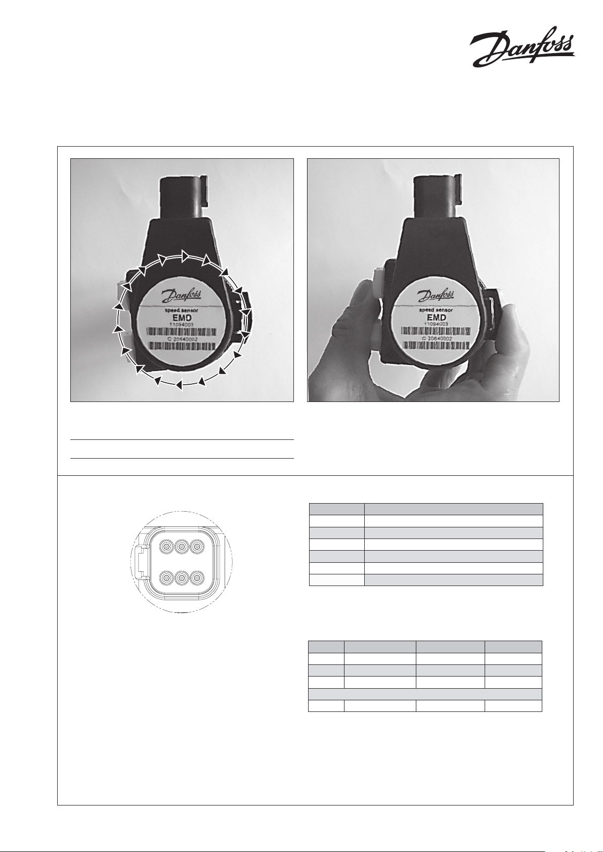
Sensor Pinout
Pin Controller function
1 Power supply 9-36 V dc
2 Power ground -
3 D 1 (confi gurable output)
4 CAN L
5 CAN H
6 D 2 (confi gurable output)
T301 081
LSHT-motors
with EMD-speedsensor
110 996 28
Turn the sensor to the desired position and mount the
sensor on the plug.
It is possible to mount the sensor in 36 positions.
110 99 628
To lock the sensor, push the clip into the sensor as shown.
Deutsch DT connector – 6 pin
© Danfoss, 2014-03 11099628 • Rev BD • Mar 2014 1
16253
4
P301 314
Deutsch DT connector 6 pin mating connector assembly:
(Not offered by Danfoss)
Color
1 Plug DT06 -6S -P O12 (black)
1 Wedgelock W6S-PO12 (green)
6 Solid Contacts 0462-209-16141 (nickel)
Options
1 Boot DT6S-BT-BK (black)
For correct mounting please see
Deutsch homepage: www.deutsch.net
Page 2
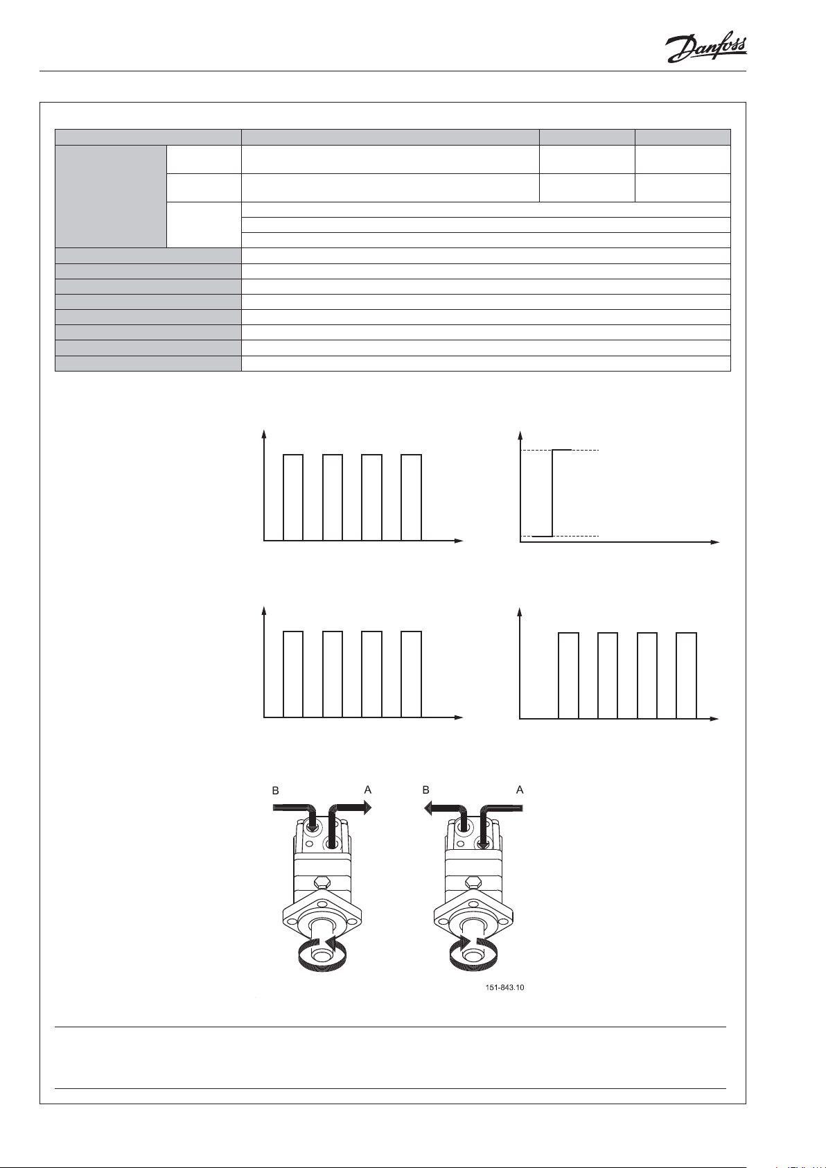
Specifi cations:
D1:
D2:
D1:
Output signal* D1 D2
Pulse mode Push-pull output. Direction = CCW: high, CW: low
Confi gurable up to 180 pulse/revolutions
Quadrature
mode
2 channels with 90° phaseshift each with
90 pulses/revolution Push-pull output
Square Wave Direction
Square Wave Phase ASquare Wave Phase
CAN mode Supports CAN 2.0B with SAE J1939 Message Protocol with Proprietary Messages
Baudrate: 250 kbaud (fi xed)
Shaft velocity: ± 2500 rpm
Speed range 0 - 2500 rpm
Supply voltage 9 - 36 Vdc
Maximum power 0.8 W
Temperature range (amibient) -30 °C to 60 °C
EMC-Immunity (EMI): 100 V/m ISO 13766
Grade of enclosure** IP 69 K
2
Vibration 30 G (294 m/s
Shock 50 G (490 m/s
)
2
)
* Confi gurable with PLUS+1® Service Tool - Please contact Danfoss for further information.
** According to IEC 529.
Pulse mode
The sensor generates a speed
dependent pulse on D1 and a
direction signal on D2.
U
High
U
High
CCW
B
T301 082
Quadrature mode
The sensor generates a speed
dependent pulse on D1 and D2
with a 90 degree phaseshift.
Direction of shaft rotation
Low
CW
U
> Udc-2V U
High
Low
< 2V
P301 345
U
Low
U
> Udc-2V U
High
Low
< 2V
P301 344
U
D2:
U
High
U
Low
U
> Udc-2V U
High
Low
< 2V
P301 344
U
High
U
Low
U
> Udc-2V U
High
Low
< 2V
P301 346
Warning
Please note that the EMD speed sensor may fail. Output signals may not represent correct rotation speed or direction.
Any application of the EMD speed sensor should be subjected to appropriate hazard and risk assessment, according to relevant
safety standards for the application.
Reliability data MTTF for the EMD speed sensor are available on request from your Danfoss representative.
2 11099628 • Rev BD • Mar 2014 © Danfoss, 2014-03
CCW CW
 Loading...