

Page 1
Application Guide
Low pressure lift ejector system
Multi Ejector solution incl. Multi Ejector Low
Pressure (LP 935/1435/1935) and AK-PC 782A
Page 2

Application Guide | Low pressure lift ejector system
Contents 1. General description ..........................................................................................................................................................3
1.1 System design with Low Pressure lift ejector ..............................................................................................3
1.2 Example system load ...........................................................................................................................................4
MT (Medium Temperature) evaporators load 50 kW ................................................................................4
LT (Low Temperature) evaporators load 10 kW ..........................................................................................4
1.3 Overall control strategy and objectives ........................................................................................................5
2. Configuration PC782A .....................................................................................................................................................5
2.1 Select plant type ....................................................................................................................................................5
2.2 Suction group MT (Capacity control) .............................................................................................................6
2.3 HP control .................................................................................................................................................................7
2.4 Condenser fan control .........................................................................................................................................7
2.5 Receiver control .....................................................................................................................................................8
2.6 IO configuration .....................................................................................................................................................9
3. What is an ejector, and how does it work? ..........................................................................................................10
3.1 Danfoss Multi Ejector design ..........................................................................................................................10
3.2 Multi Ejector Capacity Control ....................................................................................................................... 11
3.3 How does the Multi Ejector solution work? .............................................................................................. 11
4. Coolselector®2 Selecting components ................................................................................................................. 12
4.1 LP ejector selection ............................................................................................................................................ 12
4.2 GBV, Gas By-Pass #1 valve selection ............................................................................................................ 13
4.3 Check valve selection ........................................................................................................................................14
4.4 Evaporator EEV selection ................................................................................................................................. 15
5. Multi Ejector Solution™ ................................................................................................................................................ 16
2 | AB322920563002en-000103 © Danfoss | DCS (vt) | 2020.08
Page 3

Application Guide | Low pressure lift ejector system
1. General description
1.1 System design with Low
Pressure lift ejector
Low pressure lift ejector systems are simpler
systems than high-pressure ejector systems,
because they do not need the parallel
compressor in order to work and give an energy
saving (see diagram on next page). In winter
time, the system works like a normal booster
system where the gas bypass valve controls the
receiver pressure with set pressure differential,
and the evaporation pressure is controlled by
adjusting the compressor capacity according to
the needed MT evaporators’ suction pressure.
The LP ejector can be considered as an add-on
to the standard system, however there are some
additional components, and a different control
strategy needs to be applied.
Below are the most important points to take
into account when designing such a system (see
diagrams on page 4):
Setpoints and operational modes
As described, an LP ejector system can operate
with two different modes: the standard mode in
low ambient temperatures and the ejector mode
in high temperatures. How it changes from one
mode to the other and the setpoint and signals
required for this are listed below:
• In the winter condition, the ejector is working
as a high-pressure valve and is not providing
any or not enough suction mass flow to put
the system into ejector operation. The system
is performing as a standard system, but with
receiver pressure controlled with a pressure
differential of 3 bar between the pressure
in the receiver (P-rec) and the common MT
evaporators’ suction line. The pressure signal
is coming from the sensor located before the
check valve (Po-MT). The pressure in the gas
cooler is controlled based on the refrigerant
outlet temperature (Sgc) and the optimum COP
algorithm.
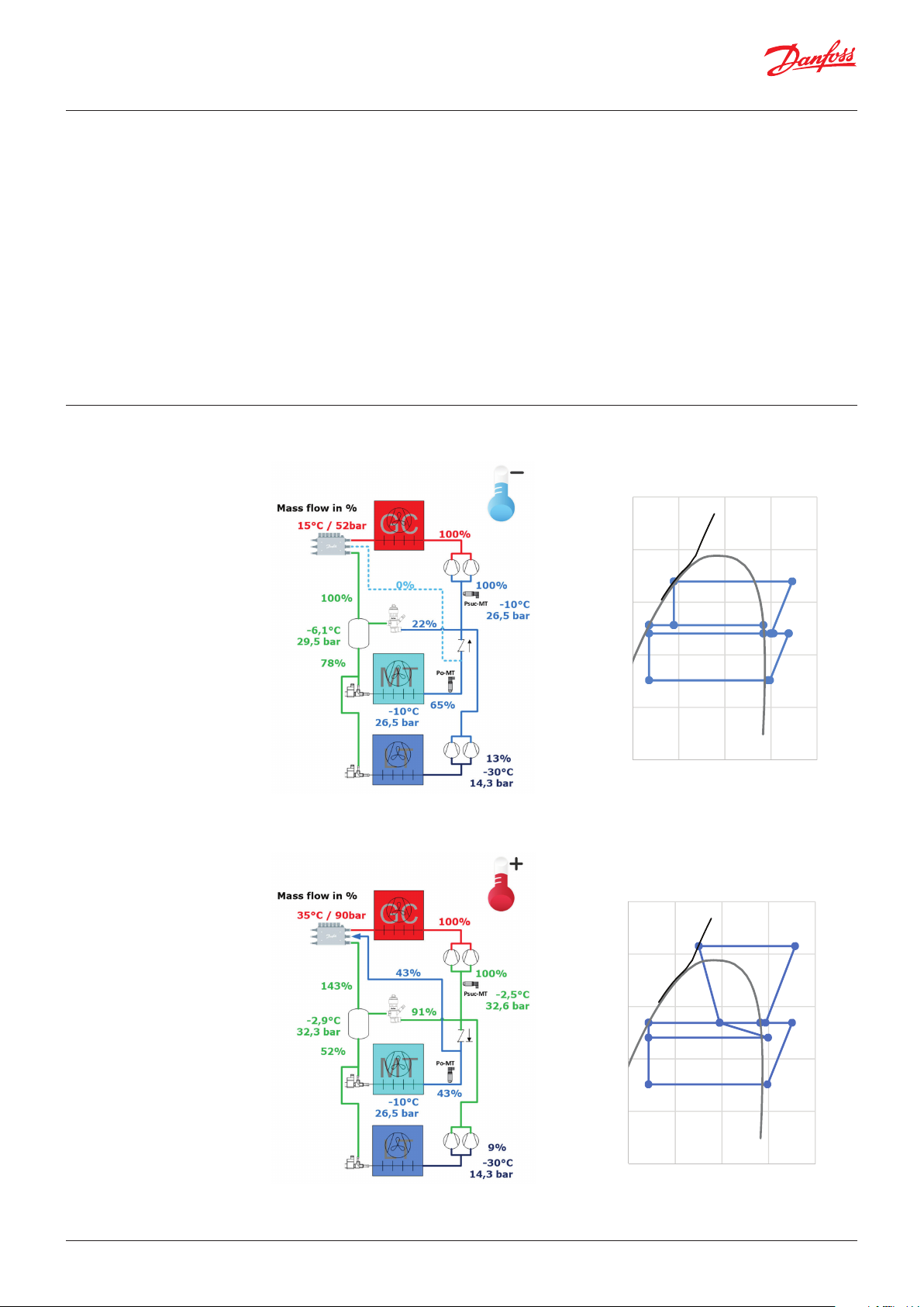
• Ambient temperatures of 17 – 18 °C result in
24 – 25 °C out of the gas cooler measured by
the temperature sensor Sgc, corresponding
to gas cooler pressure 64 to 66 bar(a). At
ambient temperatures of 17 – 18 °C there is
enough expansion work in the system for the
LP ejector to take all the mass flow from the
MT evaporators and lift it to the receiver. Since
the gas bypass valve is controlled on the basis
of pressure difference between the receiver
and MT evaporator pressure, and not fixed
pressure, the valve will start to open more and
more. Setpoint for the valve would typically be
3 bar difference and if the ejector can provide
a higher lift, the gas bypass valve will be 100%
open.
Components
The system requires some additional
components. Additionally the design criteria for
some components are different:
• Gas Bypass Valves: It will be challenging
to have one valve fulfilling good control in
both Standard and Ejector mode. In the first
mode there is limited amount of gas released
to suction MT compressors with a constant
pressure difference of 3 bar, while in the second
At 23 – 25 °C out of the gas cooler, the ejector
starts to pump all gas from the MT evaporators
and lift to the receiver with a pressure lift of
approximately 3 bar. The consequence of this is
a better COP of the system. The higher suction
pressure will also result in higher mass flow in the
same compressor and thereby a first cost saving
due to a smaller installed capacity. The first cost
saving can be as much as 30% at high ambient
temperatures and 15% energy saving compared
to a booster system.
one (LP ejector mode) there is a large amount
of gas with a minimum possible pressure
drop; our solution is with 2 x Gas Bypass Valves
(GBV). GBV #1 is a standard one and works in
all conditions, and GBV #2 mounted in parallel
with big KV value operating when the system
turns into LP Ejector mode. The idea is to have
as little as possible pressure drop across the two
GBVs, as this pressure drop will count as loss to
the LP ejector’s recovered work.
• Another option is to use a 2-way ball valve
motor mounted in parallel to GBV #1 which
can give even better system performance as
the pressure drop in the gas bypass line will be
minimal.
• Pressure sensors: The reference sensor for
controlling MT compressors should be mounted
on the common MT evaporators’ suction line
“Po_MT”, before the check valve. In systems
with MT and LT evaporators it can happen
that the MT evaporator load drops below the
minimum MT compressor capacity which will
lead to pump down situation and possible
turning off of the MT compressors. On the other
hand, LT evaporators can have a load and LT
compressors will run. To protect LT compressors’
from high pressure cut-out, a new Psuc_MT
sensor is introduced. If the pressure exceeds
the set offset pressure, the Psuc_MT will
become reference sensor for controlling the MT
compressors.
• Electronic Expansion Valves and evaporators:
The LP ejector pressure lift is relatively low.
Therefore, the system needs to be designed
accordingly, and the EEV (Electronic Expansion
Valve) for MT evaporators should be selected
according to the system requirements and
limitation. The pressure losses in evaporator
and distributors should be investigated and
designed to be a portion of the minimum
pressure lift that the ejector can provide (3
bar). Larger evaporators and distributors
may provide too high pressure loss for the LP
system. If the losses in the evaporator are high,
then it should be ensured that the system
will operate with high pressure in the gas
cooler to provide adequate pressure lift. That
can either occur when there is high ambient
temperature or when Heat Recovery is activated
in the system. The pressure losses should be
considered in the selection of the EEV
• Compressors: Compressor selection is made
using the receiver pressure at the highest
ambient temperature (design condition). This is
© Danfoss | DCS (vt) | 2020.08 AB322920563002en-000103 | 3
Page 4
80G425
80G424
80G426
160.0
Pressure bar(a)
Enthalpy kJ/kg
Danfoss
80G427
5.0
10.0
20.0
40.0
80.0
160.0
150.0250.0 350.0450.0 550.0
Pressure bar(a)
Enthalpy kJ/kg
Application Guide | Low pressure lift ejector system
1.2 Example system load
typically 6 – 7.5 bar higher than the evaporation
pressure and will yield smaller compressors
typically 20 – 30%, resulting in reduction of the
first cost of the system. The small compressor
steps in the system can be useful in the part
load situation during the cold periods.
Oil management
In booster/winter mode, the system has a safe
oil return, but when the system is in Ejector
mode, the oil will end in the receiver and will
stay there if no action is taken on it. There are
many ways to recover the oil and get it back to
the compressor. If the oil separator has a low
efficiency, the oil problem will be bigger. Part of a
safe oil return can be the LT compressors. The LT
compressors receive an oil-rich gas mixture from
MT (Medium Temperature) evaporators load 50 kW
LT (Low Temperature) evaporators load 10 kW
Danfoss
the LT evaporators. The oil is passed through the
LT compressors and can be transferred to the MT
compressors as LT discharge is connected directly
to the MT compressor suction. However, as the LT
evaporators’ load varies during the year, sufficient
oil return cannot be expected. That depends on
the load ratio between the MT and LT compressor
capacity, the oil quantity in the system and the
efficiency of the oil separator.
To be certain, an oil recovery system is needed.
By using the second pressure differential
reference “DeltaP High” and a low oil level sensor
mounted on the oil receiver, the system can
be changed from LP Ejector mode to Standard
mode. This ensures that oil will return to the MT
compressors.
Danfoss
80.0
Pressure in receiver controlled by pressure differential.
Parameter DeltaP low = 3 bar
40.0
20.0
10.0
5.0
150.0250.0 350.0450.0 550.0
Danfoss
4 | AB322920563002en-000103 © Danfoss | DCS (vt) | 2020.08
Pressure in receiver result of LP ejector lift > 3 bar
Page 5
Application Guide | Low pressure lift ejector system
1.3 Overall control strategy
and objectives
2. Configuration PC782A
The overall control objective is to maintain a
sufficiently low pressure difference between
the receiver pressure (Prec) and the evaporation
pressure (Po-MT) in order for the LP-ejector to lift
the total refrigerant flow from the refrigerated
cabinets up the receiver pressure level. The
designated MT-compressor will in this case
compress the gas (vapor) refrigerant directly from
the receiver. The pressure difference between
the sensors Prec and Po-MT, should however be
large enough for the injection valves to supply
the required refrigerant flow to the refrigerated
cabinets. If the motive energy for the ejector is
not big enough to perform the required pressure
lift, the check valve will open and the MT
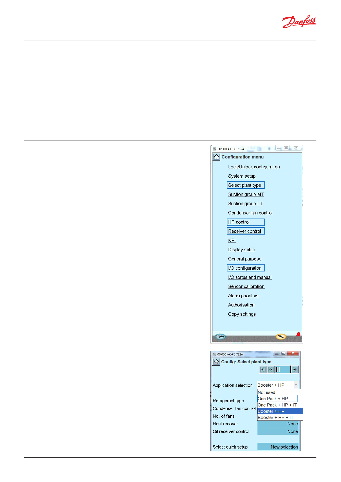
In the PC782A, the LP-system is not considered as
a dedicated “Plant type” but rather a special case
of a booster system (without IT compressor). This
means that in order to support the LP-ejector
system, a number of configurations need to be
made in respectively: ”Select Plant Type”, “Suction
Group MT”, “HP-control”, “Receiver control” and
“I/O configuration”.
compressor will take the refrigerant flow directly
from the refrigerated cabinets (instead of the
ejector).
Note that in LP ejector mode, the check valve
restricts the flow direction from the compressor
suction port (Psuc-MT) towards the MT
evaporator outlet (Po-MT). This means that if the
suction pressure (Psuc-MT) increases, it cannot
be detected in the Po-MT measurement. It is
therefore important to device a control strategy
that keeps Psuc_MT in control as well.
In the section below the control strategy and
configuration of the PC782A to support the LPejector application will be described.
2.1 Select plant type
© Danfoss | DCS (vt) | 2020.08 AB322920563002en-000103 | 5
The LP-ejector system is considered a Booster/
One pack system without any IT compressors,
therefore it is only possible to configure the Delta
P control of the receiver from these plant type
selections: "One Pack + HP" and "Booster + HP".
Page 6

80G428
Application Guide | Low pressure lift ejector system
2.2 Suction group MT
(Capacity control)
The control objective for the compressor capacity
control is to maintain a given reference for the
evaporation pressure (measured with the PoMT sensor as indicated in the drawing to the
right) by adjusting the MT compressor capacity.
Meanwhile it should be ensured that the suction
pressure (measured by Psuc-MT) is limited.
The check valve ensures that the flow can
only go from the location of the Po-MT sensor
towards the Psuc-MT sensor and not reverse. This
efficiently means that:
Psuc-MT ≥ Po-MT
Control sensors
Choosing Po-MT as the control sensor ensures
that the evaporation pressure is controlled
as desired, however this leaves Psuc-MT
uncontrolled which means that it will not be
protected against high pressure. This can lead
to dangerous situations especially in situations
where the LT compressors are starting, and the
MT compressors are at a standstill. As the LT
discharge port is connected to the MT comp.
suction port, it is not detected by the Po-MT
sensor if the LT starts and the Psuc-MT increases.
Hence, Po-MT and Psuc-MT are both used as
control sensors in such a way that the one with
the “most critical” reading is used as input for the
MT compressor capacity control.
The “most critical” sensor value is determined
in the following way: The maximum expected
pressure lift that the LP-ejector is capable of is
P_max=8 bar (“Psuc max offset”), so this will
also be the maximum pressure difference that
should be expected/allowed between Psuc-MT
and Po-MT under normal operation.
Danfoss
This means that the capacity control has two
objectives:
1. Keep Po-MT close to the Po-MT reference (“ToMT reference”)
2. Keep Psuc-MT close to the Psuc-MT reference
(“Tsuc reference”), where
Psuc reference=Po-MT reference+Psuc max offset
The decision of which is “most critical” is simply
determined by which of the two controller
objectives that has the largest control error.
Under the suction group for the MT, the selection
of running with two control sensors, Po and
Psuc, is made. By selecting “Po-MT + Psuc-MT”
as control sensor, the capacity control and the
receiver control are prepared for the DeltaP
control intended for the LP-ejectors. With this
selection, the setting of “Psuc max offset” appears
below - the default value is 8 bar.
6 | AB322920563002en-000103 © Danfoss | DCS (vt) | 2020.08
Page 7

80G429
Application Guide | Low pressure lift ejector system
2.3 HP control
2.4 Condenser fan control
As for all the Multi Ejector types the LP-ejector
is used as actuator for controlling the gas
cooler pressure. This means that the individual
ejector step will be coupled in and out in order
to maintain the optimal gas cooler pressure
(Pgc,ref) according to ambient temperature (Sc3)
and temperature reference out of gas cooler (Sgc,
ref).
The set-up is the same as for a booster system.
Note the Pgc,ref is determined based on Sgc,ref,
which is again determined based on Sc3
(ambient temperature). In case the measured Sgc
drifts more than 2K above the Sgc,ref, the Pgc,ref
will follow the measured Sgc instead of the Sgc,
ref.
Danfoss
© Danfoss | DCS (vt) | 2020.08 AB322920563002en-000103 | 7
Page 8

Application Guide | Low pressure lift ejector system
2.5 Receiver control
The receiver pressure is controlled using the
gas bypass valve (GBV). One or two valves in
sequential control mode might be used mainly to
ensure low pressure drop across the GBV in the
ejector mode where the MT compressor sucks
directly from the receiver through the GBV.
The receiver pressure is controlled with a fixed
“Delta P Low”(default 5 bar, but in a real system
preferably 3 bar) over the expansion valves and
MT evaporators.
Prec reference = Po-MT reference + Delta P low
Note that reference calculation for the receiver
is based on the reference of “Po-MT” and not
the measured value, meaning that the “Prec
reference” will remain constant irrespectively of
the actual value of Po-MT. This avoids the risk of
Prec getting pulled down into the neutral zone of
the MT compressors, e.g. during a pump down,
which would lead to a critical deadlock situation
where no cooling is provided.
By setting the control sensor to “Po-MT +
Psuc-MT” the receiver is prepared for Delta P
control. In the receiver two predefined Delta P
references “Delta P low” and “Delta P high” are
configured. It is possible to switch between the
two references by activating a digital input (DI).
“Delta P High enable” is now visible under the I/O
configuration.
Oil return
In the ejector mode, oil will accumulate in the
receiver and not return to the MT compressors.
Therefore, a special oil return strategy must be
devised. An oil-return cycle must be executed
when the low oil level switch in the oil receiver
indicates critical oil level. Oil-return strategy
efficiently means shifting to standard mode. This
can be done by increasing the receiver pressure
to a level where the LP-ejector cannot lift (to the
“Delta P high” setpoint). This means that GBV
will start closing and the check valve will open,
allowing the oil to return to the MT compressor
from the evaporator outlet.
Vrec output type
In winter mode, the GBV#1 secures that the
receiver pressure is maintained around the
requested setpoint. In the LP ejector mode
it will not be possible for the GBV#1 to keep
the receiver pressure at or below its reference
though the valve/valves are fully open. This is
because the LP-ejector in this scenario can lift
the total evaporated flow of refrigerant out of
the MT evaporators up and above the “Prec
reference”. This will cause the receiver control to
saturate the GBVs at 100% and the check valve
to close, bringing the system into LP ejector
mode. In ejector mode, the MT compressors
will remove the gas (vapor) refrigerant directly
from the receiver (as the check valve is closed),
but they will do so through the fully open GBV.
It is therefore important in the ejector mode to
reduce the pressure drop across the GBV(s), as
this results in increased compressor work. This
is the reasoning for the request for supporting
two sequential operated GBVs. The GBVs can be
different sizes.
Separator
Receiver
Danfoss
80G431
8 | AB322920563002en-000103 © Danfoss | DCS (vt) | 2020.08
Page 9

80G430
Application Guide | Low pressure lift ejector system
As with 2 Stepper (sequential) the requested
Opening Degree is split evenly. The “Kp” default
was 7 but should now be 7/2=3.5
Delta P low
“Delta P low” is the intended setpoint for
operation when the LP-ejector is sufficient (lifting
the total mass flow to the receiver).
Note: The “Delta P low” setting must be larger
than half the neutral zone of the MT capacity
control (which is
5K
= 2.5 ~ 2.3 bar
2
),
hence avoiding that the receiver pressure
can enter the neutral zone of the MT. This can
otherwise lead to a situation where the MT
compressor will not start after a standstill. The
setpoint for “Delta P low” should be lower than
the pressure lift that the ejector is capable of, but
large enough to secure the necessary pressure
drop over the expansion valves. Recommended
setting is 3 bar (default setting is 5 bar).
Delta P high
“Delta P high” is the setpoint that the receiver
will follow when the DI “Delta P High enable” is
enabled. The intention is that if the oil level in
the oil receiver is low, this DI is triggered causing
the reference to go to a level higher than what
the ejector is capable of lifting (more than 8 bar,
the “Psuc Max Offset” ).This efficiently causes
the check valve to open (see description in the
receiver control), enabling the oil return to the
compressor. Default setting is 10 bar (larger than
“Psuc Max Offset” default 8 bar).
Delta P high delay
“Delta P high delay” is a user defined delay timer
which delays the switchback from the “Delta P
high” to the “Delta P low” setpoint. The intention
is that if the “Delta P high” has been triggered due
to a low oil-receiver level, then the system should
stay in this “oil-return mode” for a certain time
(Delta P high delay) after the low oil level has
disappeared. This in order to secure a sufficient
return of oil (see also section below on oil return).
Default setting is 0 min.
Danfoss
2.6 IO configuration
When the AK-PC controller has been configured
for control of an LP ejector system, several input
and output need to be configured.
This includes the new Psuc_MT sensor (analogue
input), the signal for changing mode for oil return
(digital input) and the output used for controlling
the Multi Ejector (Digital Output).
The outputs used for controlling the smallest
ejectors must be of the Solid State Relay type
(SSR).
In this example the four smallest ejectors are
configured to be controlled by the four SSR
outputs available on the AK-PC controller (IO
points 1-12 to 1-14).
The ejector always has higher priority than the
HP valve. So although it is configured, it will not
be used except in the P-bands at high/low Pgc.
In most cases it is preferred to operate without
the HP valve. In this case the output type for the
HP valve can be left unconfigured.
© Danfoss | DCS (vt) | 2020.08 AB322920563002en-000103 | 9
Page 10

Danfoss
P
32F870.10
Application Guide | Low pressure lift ejector system
3. What is an ejector, and
how does it work?
An ejector is a device that utilizes the energy
from the high pressure work. The ejector converts
the high pressure potential energy in the motive
flow (primary) into kinetic energy, drawing a flow
from the suction port (secondary flow).
The process, shown in the diagram to the right, is
driven by the high pressure CO gas leaving the
gas cooler. The gas enters the ejector at the high
pressure port (PH) and flows through the throat,
causing the flow to accelerate. At the exit of the
ejector nozzle, the gas is at supersonic speed,
creating a low pressure (PS). As low pressure (PS)
is lower than the pressure (PL) at the suction
(secondary) nozzle, CO is flowing from the
suction port into the ejector. The two flows are
mixed in the mixing chamber and the pressure
is gradually increased. The flow finally enters the
diffuser at the end of the ejector. Because of the
conic diffuser shape, the flow gradually slows
down, and the pressure is increased. This means
that the kinetic energy of the flow (velocity)
is converted to potential energy (pressure).
After leaving the diffuser, the gas is at a higher
pressure (PD) than the suction pressure (PL).
32F996.12
Nozzle Throat Exit Mixing chamber Diffuser
H
P
P
Pressure
P
P
H
D
L
S
Intake due to
pressure differential
P
S
P
L
Pressure increase due to
reducing flow velocity
P
D
3.1 Danfoss Multi Ejector
design
All ejectors in the Danfoss portfolio have a high
pressure inlet for CO gas coming from the gas
cooler, a suction inlet from MT evaporators and
an outlet for returning the gas and liquid to the
receiver.
The coils activating the individual ejectors are
available from 110 – 230 V, 50 and 60 Hertz.
The gas ejectors are delivered with three pressure
transmitters, used for pressure control in the pack
controller.
Each block has a variable number of ejectors of
different sizes mounted vertically.
Coils adv. (230 V DIN and 120 V UL all 50 – 60 Hz)
HP Pressure
transmitter
MT Pressure
transmitter
Multi Ejectors LP are available with 4 to 6 ejectors.
The capacity demand is matched by using
different numbers and combinations of ejectors.
The characteristics of the ejectors remain the
same no matter how many ejectors are in use.
On each individual ejector a built-in non-return
valve prevents backflow, removing the need for
external check valves in suction lines.
Each individual ejector and the strainer are easily
serviced by simply removing the four mounting
screws, using a flat screwdriver to lift the ejector
or strainer, and pulling it out of the block. The
strainer can easily be taken apart for cleaning or
replacement.
Strainer
HP inlet from
gas cooker
Suction inlet from
MT evaporator
Danfoss
Outlet to
receiver
Receiver pressure
transmitter
All pressure transmitters MBS 8250 with round Packard, radiometric output and 7/16-20 UNF (same type as CCMT valves)
10 | AB322920563002en-000103 © Danfoss | DCS (vt) | 2020.08
Page 11

2500
Step
6
5
4
3
2
1
Mass flow [kg/hr @ 90 bar 35C]
Application Guide | Low pressure lift ejector system
3.2 Multi Ejector Capacity
Control
3.3 How does the Multi
Ejector solution work?
Multi Ejector capacity control is achieved
through a binary coupling of various capacities
of a number of ejectors. The Multi Ejector LP, for
2000
example, comes in three versions. The 4-ejector
version has ejectors providing 60 kg/h, 125 kg/h,
1500
250 kg/h and 500 kg/h resulting in a total of 935
kg/h of motive mass flow.
The 5-ejector version has an additional 500 kg/h
ejector providing a total of 1435 kg/h of motive
1000
500
mass flow.
0
The 6-ejector version has two additional 500 kg/h
ejectors providing a total of 1935 kg/h of motive
mass flow. This allows to modulate capacity in
32 steps between 0 and 1935 kg/h. But if more
capacity is required, a second Multi Ejector can
be added which will be controlled parallel to the
first one.
12345678910 11 12 13 14 15 16 17 18 19 20 21 22 23 24 25 26 27 28 29 30 31 32
LP 60 Ejector 1
LP 125 Ejector 2
LP 250 Ejector 3
LP 500 Ejector 4, 5, 6
The AK-PC equalizes the number of on/off switches between
equal sized ejectors to optimize the electrical and mechanical
lifetime of the AK-PC.
There are 4 different ejector cartridge sizes for LP Multi Ejectors (approx. 60, 125, 250 and 500 kg/h).
The largest ejectors are placed closest to the connectors.
Multi Ejector blocks
Type Code no. Product name
CTM 6 032F5678 CTM Multi Ejector LP 935 60 125 250 500
CTM 6 032F5693 CTM Multi Ejector LP 1435 60 125 250 500 500
CTM 6 032F5679 CTM Multi Ejector LP 1935 60 125 250 500 500 500
Ejector 1 Ejector 2 Ejector 3 Ejector 4 Ejector 5 Ejector 6
kg/h kg/h kg/h kg/h kg/h kg/h
Danfoss
84B8247
Ejector
Ejector
Ejector
Ejector
Ejector
Ejector
The flow enters the Multi Ejector through the
strainer in front of the high pressure inlet. The AKPC controller decides which ejector is activated to
meet the requested capacity. Through the open
nozzle, the high-pressure flow is transformed into
high velocity flow. The high velocity creates a
very low pressure, making the suction of the MT
possible.
OFF OFF OFF ON ON ON
High
pressure inlet
MT
pressure inlet
Receiver
pressure inlet
The flow from the MT suction inlet enters
the ejector through the check valve, mixing
with the high velocity flow. The mixed flow is
slowed down in the diffuser part of the ejector,
transforming the velocity to pressure. From here
the mixed flow is lead to the receiver and thereby
recovering a part of the expansion work.
Danfoss
84B8248
© Danfoss | DCS (vt) | 2020.08 AB322920563002en-000103 | 11
Page 12

Application Guide | Low pressure lift ejector system
4. Coolselector®2
Selecting components
4.1 LP ejector selection
DeltaP … LP ejector pressure lift
DeltaP=P_receiver – Po_MT = 32,3-26,5 = 5,8 bar
m_comp_MT … Motive flow
m_evap_MT … Suction flow
m_BP … Gas By-pas flow
er … Entrainment ratio
m
evapMT
er = = = 0,43
m
compMT
719
1656
Gas quality in receiver
m
compMT
BP
+ m
evapMT
x = = = 0,636 ~ 0,64
m
1512
1656 + 719
Operating envelope
12 | AB322920563002en-000103 © Danfoss | DCS (vt) | 2020.08
Page 13

Application Guide | Low pressure lift ejector system
4.2 GBV, Gas By-Pass #1
valve selection
Select Gas By-Pass valve like for standard Booster system, because even you will run in summer time
in LP ejector mode; there will be a time where we will turn the system to standard operation with Prec
Delta P high to get oil back.
Valves and Line Components
Transcritical gas bypass valves
Selection Sgc 40 °C ; DeltaP high 10 bar
Gas bypass line (transcritical system, R744, Gas bypass valve)
Selection Sgc 24 – 25 °C; DeltaP low 3 bar; Standard mode
LP ej selection to find out Sgc temperature when the ejector pressure lift exceeds DeltaP Low
DeltaP … LP ejector pressure lift
DeltaP=P_receiver – Po_MT = 29, 56-26, 5 ~ 3 bar
© Danfoss | DCS (vt) | 2020.08 AB322920563002en-000103 | 13
Page 14

Application Guide | Low pressure lift ejector system
GBV #1 selection
Gas bypass line (transcritical system, R744, Gas bypass valve)
Conclusion:
We receive very similar results for high ambient temperature and DeltaP high (10 bar) and at
temperature out of the gas cooler 24 – 25 °C and DeltaP low (3 bar)
4.3 Check valve selection
Valves and Line Components
Check valves
14 | AB322920563002en-000103 © Danfoss | DCS (vt) | 2020.08
Page 15

Application Guide | Low pressure lift ejector system
4.4 Evaporator EEV selection In section “System design with Low Pressure lift ejector” point 5 it was explained what the limitations
for selecting right AKVP/PS are. If e.g. the pressure differential Delta P Low is 3 bar and we assume the
pressure loss on suction line is 1 bar, and distributor + evaporator additionally 1 bar, then there is 1 bar
pressure difference for MT EEV left.
Valves and Line Components
Electronic expansion valves
Delta P Low = 3 bar
Pressure drop 2 bar for suction line + distributor + evaporator
1 bar pressure drop for AKV PS
© Danfoss | DCS (vt) | 2020.08 AB322920563002en-000103 | 15
Page 16

5. Multi Ejector Solution™
Danfoss offers a wide range of market leading Multi Ejectors. Supported by 3 MBS 8250 sensors, coils
with LED plug.
Multi Ejector LP 935
The Multi Ejector Low Pressure (LP) with a nominal motive mass flow capacity of 935
kg/h is the smallest in the LP range and consists of 4 LP ejectors, 2 blanks and 1 strainer.
It is recommended for stores with a refrigeration load in the range of 18 – 35 kW.
Multi Ejector LP 1435
The Multi Ejector Low Pressure (LP) with a nominal motive mass flow capacity of 1435
kg/h consists of 5 LP ejectors, 1 blank and 1 strainer.
It is recommended for stores with a refrigeration load in the range of 18 – 53 kW.
Multi Ejector LP 1935
The Multi Ejector Low Pressure (LP) with a nominal motive mass flow capacity of 1935
kg/h is the biggest in the LP range. It consists of 6 LP ejectors, and 1 strainer.
It is recommended for stores with a refrigeration load in the range of 18 – 72 kW.
Controller AK-PC 782A
Danfoss offers a wide range of market leading Pack Controllers.
Being the flagship and best in class controller for transcritical CO packs controls, the
AK-PC 782A offers the highest possible efficiency with the Multi Ejector, CTM.
The complete application control features:
• Complete booster pack control of up to 3 suction groups (max. 12 compressors) and
high pressure system
• Significant savings with heat recovery for tap water and heat reclaim
• Extensive control of oil flow and pressurization
• Best in class safety monitoring and fail-safe functions
• Minimal energy consumption while ensuring optimal food quality
• Auto-configured, easy-to-use graphical representation with Danfoss System Manager
• Independent, customized control and monitoring of auxiliary function
Temperature sensors and pressure transmitters
Danfoss offers a comprehensive range of sensors for temperature and pressure sensors
developed to meet the requirements of the entire pack application.
The sensor range delivers the following key features and benefits:
• Long term reliability minimize system downtime
• Robust construction protects again mechanical shock and vibration
• Temperature sensor design ensures fast response time and precise measurement
• Hermetically sealed pressure element ensures no leakage
• Pressure transmitter output calibrated for perfect fit to the application
• Pulse snubber ensures protection against liquid hammering, cavitation or pressure peaks
© Danfoss | DCS (vt) | 2020.08 AB322920563002en-000103 | 16
ADAP-KOOL®
 Loading...