

Page 1
Service Kit Instructions
Series 42
Loop flushing valve
PURPOSE:
The loop flushing consists of the loop flushing shuttle valve
and the loop flushing relief valve. The assemblies may be
removed for cleaning and installation of new O-rings. The
relief valve poppet may be exchanged for one with a different
flow rating. Sauer-Sundstrand strongly recommends using all
new hardware include in the kit.
PROCEDURE:
Loop Flushing Valve
1. Remove the loop flushing valve plug from the pump
housing (1 1/16 in Hex). Remove the O-ring from the
plug.
2. Remove the loop flushing valve spool assembly from
the housing.
3. Inspect the parts for damage or foreign material. The
centering spring must be securely retained to the
spool by the washer.
4. Install the loop flushing valve spool assembly into its
bore. Install a new O-ring on the loop flushing plug
and torque to 27-37 Nm (20-35 ft•lbf).
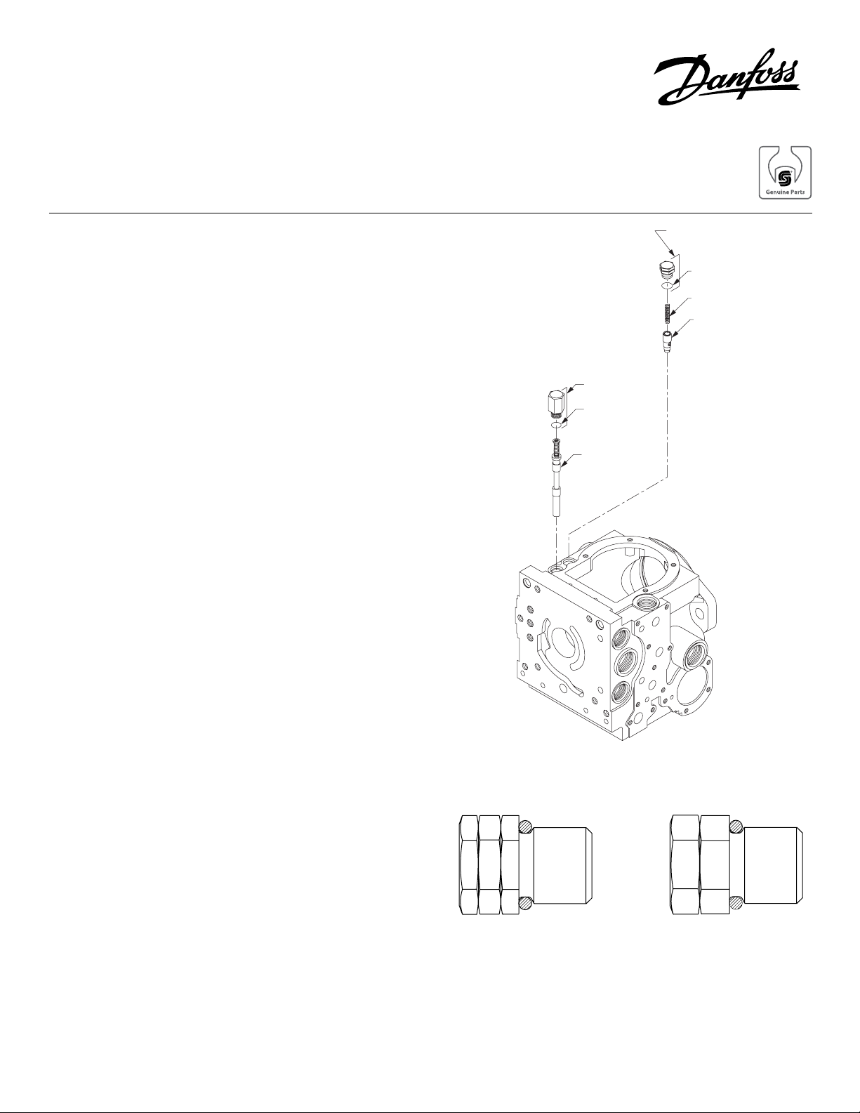
Loop Flushing
Relief Plug
O-Ring
Spring
Poppet
Loop
Flushing Plug
O-Ring
Loop Flushing
Spool Assembly
Loop Flushing Relief Valve
1. Remove the loop flushing relief valve external hex
plug (5/8 in Hex) from the pump housing. Remove the
O-ring from the plug.
2. Remove the spring and poppet from the housing.
3. Remove and discard all shims which are found
between the spring and valve plug.
4. Inspect the poppet and mating seat in the housing for
damage or foreign material. Inspect the orifice in the
valve poppet.
6. Install a new O-ring on the valve plug. Reinstall the
poppet, spring, and plug (with O-ring) into the pump
housing. Torque plug to 21-34 Nm (15-25 ft•lbf).
Note:
There are two valve plugs in each kit. In order to
determine which plug to use it is necessary to know
the charge pressure. If the charge pressure is greater
than 18 bar, use the plug with two identifying grooves.
If the charge pressure is less than 18 bar, use the plug
with one identifying groove.
Loop Flushing Valve Components
rab 81 wolebevoba dna rab 81
Relief Valve Plugs
© Danfoss, 2013 BLN-10121 • Rev AA • September 2013 1
 Loading...