

Page 1
Service Kit Instructions
Series 40 - M46
Load Control Field Conversion Kit Installation Instructions
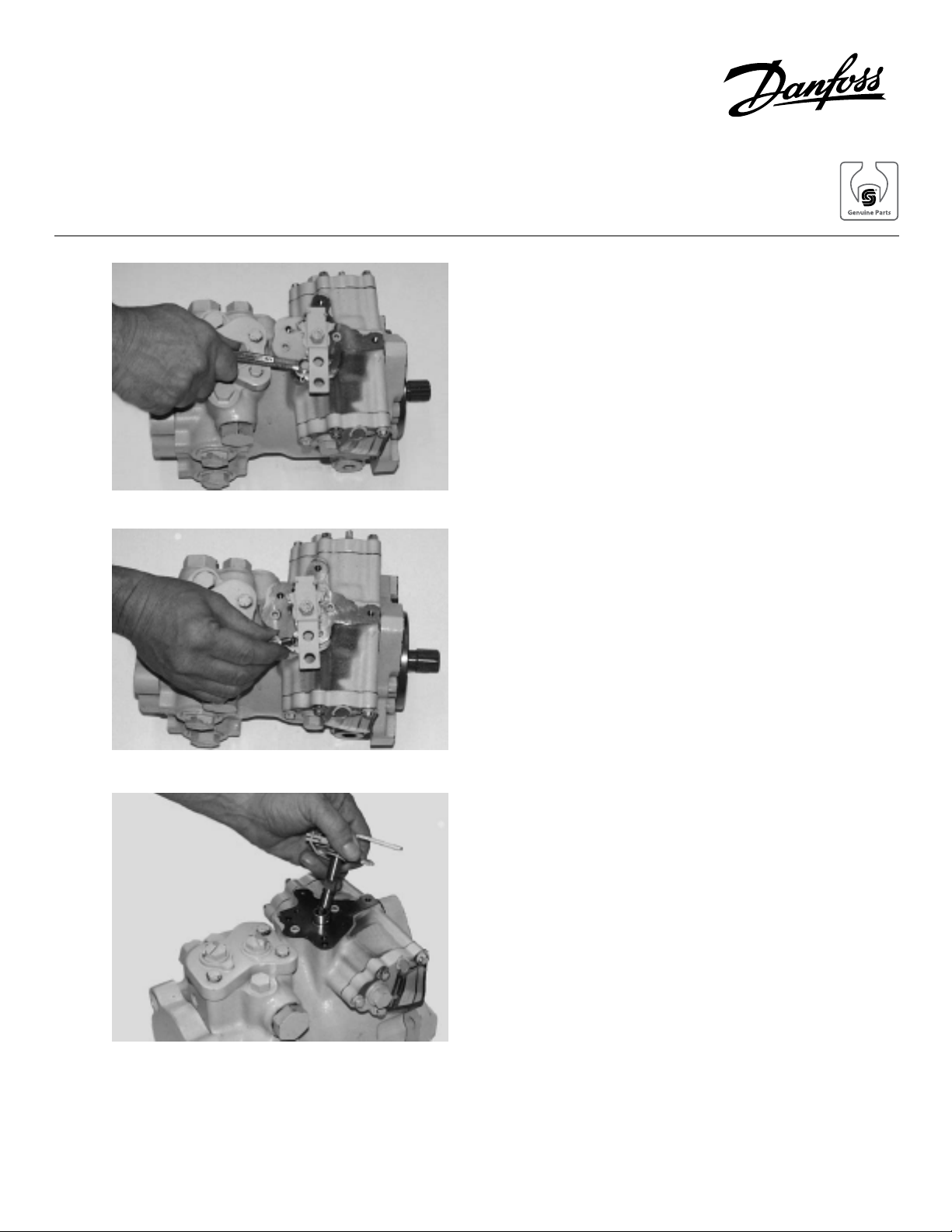
With the pump controller facing upward loosen the screw or
flange head screw retaining the neutral bracket to the
housing using a 7/16” or 3/8” wrench.
Remove the screw and washer or flange head screw from
the housing.
Remove the MDC spool assembly from the housing.
© Danfoss, 2013 BLN-10193 • Rev AA • September 2013 1
Page 2
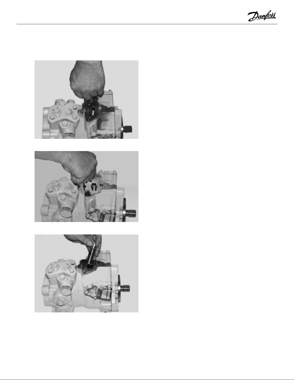
Remove the 2 plugs on both sides of the control sleeve.
On pumps with date code 86-14 or below, remove the
control inlet using a 9/16 in. hex wrench. On pumps with
dates code above 86-14, use a 3/16 in. internal hex wrench.
Remove control inlet orifice.
Remove the control sleeve from the unit by carefully
gripping the end of the sleeve with pliers and pulling out.
© Danfoss, 2013 BLN-10193 • Rev AA • September 2013 2
Page 3
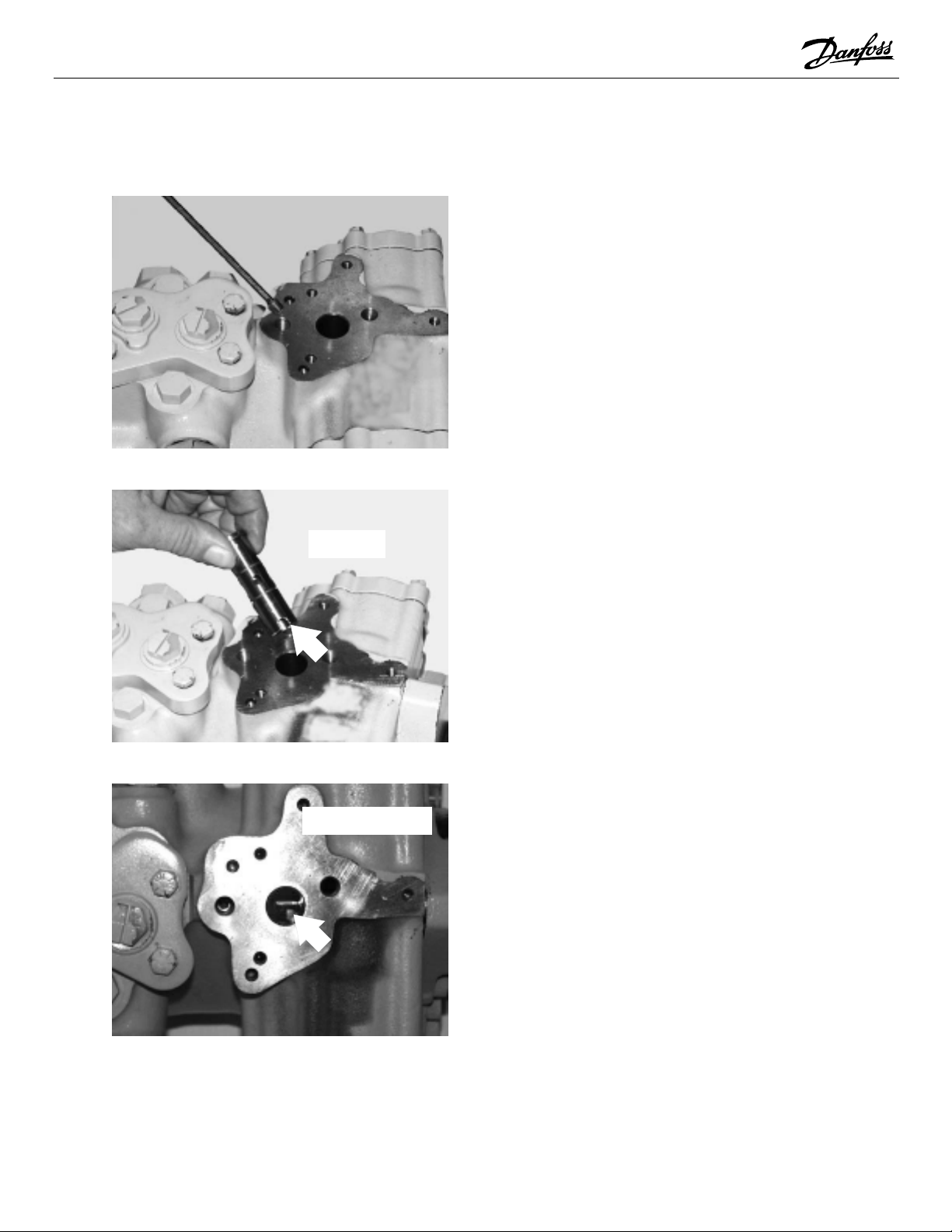
S L O T
Install screened orifice. Torque to 2 to 3 Nm [20 to 30 lbf •in]
Align the new control sleeve so its slot will engage the
swashplate feedback pin.
FEED BACK PIN
Swashplate feedback pin.
© Danfoss, 2013 BLN-10193 • Rev AA • September 2013 3
Page 4

Carefully push the control sleeve all the way down by hand.
Using petroleum jelly to retain them, make sure all O-rings
are in place on the bottom side of the EDC.
Carefully install the EDC onto the pump.
© Danfoss, 2013 BLN-10193 • Rev AA • September 2013 4
Page 5

Install the 4 mounting screws.
Torque screws to 13-14 Nm [10 to 12 lbs•ft]
© Danfoss, 2013 BLN-10193 • Rev AA • September 2013 5
Page 6

Stamp information on new tag.
STAMP NEW MODELS NUMBERS
IN THIS AREA
“M46-20578”
STAMP THE DATE THE EDC
WAS INSTALLED
IN THIS AREA
STAMP COMPLETE ORIGINAL
SERIAL NUMBER IN THIS AREA
Loosen and remove retaining screw with tag attached.
Combine old and new tags.
Install screw with tags in place and torque screw to 15 - 18
Nm [11-13 lbf•ft].
© Danfoss, 2013 BLN-10193 • Rev AA • September 2013 6
Page 7

Electrical Displacement Control (EDC) Neutral
Adjustment
Remove the electrical connector at the EDC. Install a 0 to
300 PSI (0 to 21 BAR) gauge in each servo port.
Warning
The following procedure may require the
vehicle/machine to be disabled (wheels raised off
the ground, work function disconnected, ect.)
while performing the procedure in order to prevent injury to the technician and bystanders.
Start the prime mover and slowly accelerate to normal
operating RPM.
Loosen lock nut with 1/2” wrench and slowly rotate the
neutral adjustment screw, with 5/32” internal hex wrench,
until the pressure is equal on both servo gages.
Slowly rotate the neutral adjust screw until one of the servo
gauges starts to increase in pressure.
Noting the amount of rotation, slowly rotate the neutral
adjust screw in the opposite direction until the other servo
gauge begins to increase in pressure.
Turn the neutral adjust screw back one-half the amount
noted above. Hold the neutral adjust screw and torque the
lock nut to 25 to 30 lbs•in. (2.8 to 3.4 Nm).
Stop the prime mover. Connect the control input. Remove
the servo pressure gauges. Return the machine to normal
operating condition. Restart prime mover and assure that
hydrostatic system is in neutral.
© Danfoss, 2013 BLN-10193 • Rev AA • September 2013 7
 Loading...