

Page 1
Application guidelines
Danfoss scroll for refrigeration
LLZ013 to 034 with NI/VI/LI
Low temperature
50-60 Hz - R404A, R507
http://cc.danfoss.com
Page 2

Page 3

Content
GENERAL INFORMATION ........................ 4
PRODUCT INFORMATION ....................... 5
Features..................................................... 5
Overview ......................................................................5
Compressor model designation ............. 6
Nomenclature ............................................................6
Technical specications ........................... 7
50-60 Hz data .............................................................7
Dimensions ............................................. 10
Single compressors LLZ013-015-018 ...............10
Single compressors LLZ024 .................................11
Single compressors LLZ034 ...............................12
Electrical data, connections and wiring 14
Motor voltage ...........................................................14
Wiring connections ................................................ 14
IP rating .......................................................................15
Three phase electrical characteristics ............. 15
Motor protection.....................................................16
Approval and certicates ...................... 17
Pressure equipment directive ............................17
Low voltage directive ............................................ 17
Machines directive .................................................17
Internal free volume...............................................17
SYSTEM DESIGN ..................................... 18
Design piping ......................................... 18
General requirements ...........................................18
Design compressor mounting .............. 19
General requirements ...........................................19
Single compressor requirements ......................19
Manage sound and vibration ................ 20
Compressor sound radiation ............................. 20
Mechanical vibrations ...........................................21
Gas pulsation ............................................................21
Manage operating envelope ................. 22
Requirement ............................................................ 22
Evaluate the risk ...................................................... 24
Theory of Injection cycle ....................... 25
Theory of Vapor injection cycle ........................ 25
Theory of liquid injection cycle ........................ 25
TREV installation ..................................................... 26
Manage superheat ................................. 28
Requirement ............................................................ 28
Evaluate the risk ...................................................... 28
Test, criteria and solutions .................................. 28
Manage o cycle migration ................... 29
Requirement ............................................................ 29
Evaluate the risk ...................................................... 29
Test, criteria and solutions .................................. 29
Control logic ...........................................30
Safety control logic requirements ................... 30
Cycle rate limit requirements ............................ 30
Oil management logic recommendations ... 30
Defrost logic recommendations ...................... 30
Pump-down logic recommendations .............31
Provide power supply and electrical
protection ............................................... 32
Wiring information ................................................ 32
INTEGRATION INTO SYSTEMS ..............33
Reduce moisture in the system ............. 33
Requirements .......................................................... 33
Solutions ................................................................... 33
Assembly line procedure ....................... 34
Compressor storage .............................................. 34
Compressor holding charge .............................. 34
Handling ................................................................... 34
Piping assembly...................................................... 35
System pressure test and leak detection ...... 35
Vacuum evacuation and moisture removal 36
Refrigerant charging ............................................. 36
Dielectric strength and insulation resistance
tests ............................................................................. 36
Commissioning ....................................... 37
Preliminary check....................................................37
Initial start-up ...........................................................37
System monitoring .................................................37
Dismantle and disposal ......................... 38
ORDERING INFORMATION ................... 39
Packaging ............................................... 39
Ordering codes ....................................... 40
Accessories .............................................. 41
3FRCC.PC.039.A1.02
Page 4
General Information
PRODUCT INFORMATIONSYSTEM DESIGNINTEGRATION INTO SYSTEMORDERING INFORMATION GENERAL INFORMATION
Danfoss scroll compressors are designed and
manufactured according to the state of the
art and to valid European and US regulations.
Particular emphasis has been placed on
safety and reliability. Related instructions are
highlighted with the following icons:
R
This icon indicates instructions to avoid
reliability risk.
This icon indicates instructions to avoid
safety risk.
You are strongly advised to follow these
instructions. For any deviation from the
guidelines, please contact Danfoss Technical
Support.
In any case, Danfoss accepts no liability as a result
of the improper integration of the compressor
into the unit by the system manufacturer.
4 FRCC.PC.039.A1.02
Page 5
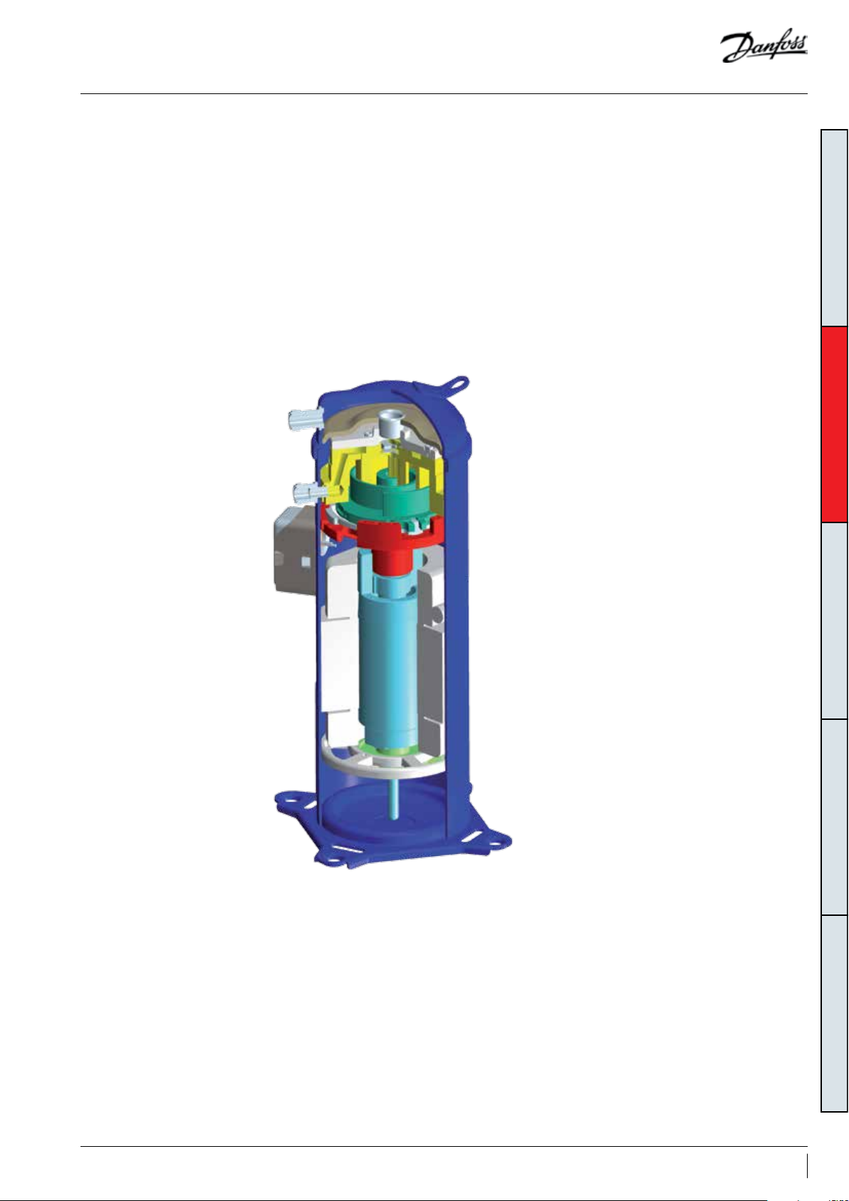
Features
Overview Economized compressor: In the LLZ range of
Danfoss scroll compressor for refrigeration, LLZ,
with its unique scroll design and manufacturing
process exibility, oers a highly ecient solution
for demanding refrigeration applications.
This new family of refrigeration scroll
compressors includes 5 sizes of low temperature
scroll compressors designed for commercial
refrigeration applications. These compressors are
engineered for refrigeration and oer cooling
capacity from 5 to 12 kW (4 to 10 HP) at common
voltages and frequencies as well as any of the
common refrigerants (R404A / R507).
refrigeration scrolls, the compressors can work
with the economizer line activated, named as
economized compressor; or with the economizer
line disabled, named as standard compressor. The
economized compressor has been developed to
provide improved performance and an enlarged
operating envelope in refrigeration applications.
The economized compressor system presents
benets over standard refrigeration compressor
systems of equivalent horse power due to the
following:
• Capacity improvement: The capacity is
improved without increasing compressor
displacement, as it is increased by further
increasing system sub cooling with a
heat exchanger acting as an economizer
(connected to the compressor economizer
line). Furthermore a smaller economized
compressor can be used to achieve the same
capacity as a larger standard compressor,
leading to cost advantages.
• Eciency improvement: With a suitable sized
heat exchanger, the eciency improves
due to the fact that the gain in capacity is
greater than the increase in power that the
compressor consumes.
GENERAL INFORMATIONSYSTEM DESIGNINTEGRATION INTO SYSTEMORDERING INFORMATION PRODUCT INFORMATION
• Enlarged operating envelope: The injection
of vapour through the economizer line
will reduce the discharge temperature and
therefore enlarge the operating envelope
based on the same suction status.
Standard compressor with liquid injection: The
standard compressor can also connect with a
liquid valve to reduce the discharge temperature
and enlarge the envelope.
• Enlarged operating envelope: The liquid
injection of refrigerant into the compressor
will ash and absorb heat from the
compressed gas and scroll set leading to
cooling of the discharge gas, thus keeping
the discharge gas temperature within safe
limits. The enlarged operating envelope is
therefore based on the same suction status.
5FRCC.PC.039.A1.02
Page 6
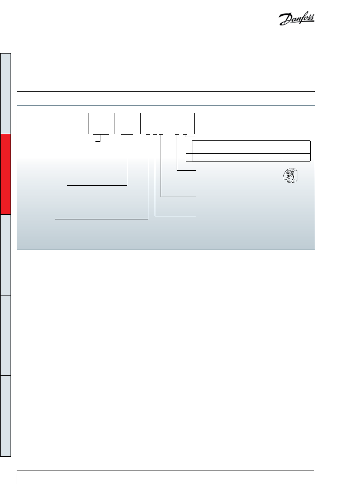
Compressor model designation
Nomenclature
GENERAL INFORMATIONSYSTEM DESIGNINTEGRATION INTO SYSTEMORDERING INFORMATION PRODUCT INFORMATION
Family, Refrigerant & lubricant
LLZ: low temperature refrigeration,
R404A, R507 & PVE lubricant
Nominal capacity
In thousand Btu/h at 60 Hz,
ARI, LBP conditions
Model variation
T: design optimised for refrigeration
Danfoss scroll compressor LLZ for R404A, R507
is available as single compressor and can be
assembled in manifolding combinations.
Type FeaturesMotorSize
LLZ Q 9T 4 L
013
9
The example below presents the compressor
nomenclature which equals the technical
reference as shown on the compressor
nameplate. Code numbers for ordering are listed
section “Ordering information and packaging”.
Other features
Oil sight
glass
Threaded
Tubing and electrical connections
Q: rotolock connections, screw terminals
Motor protection
L: internal motor protection
Motor voltage code
2: 200-220V/3~/50 Hz & 208-230V/3~/60 Hz
4: 380-415V/3~/50 Hz & 460V/3~/60 Hz
9: 380V/3~/60 Hz
Oil
equalisation
None Schrader None
Oil
drain
LP gauge
port
equalisation
Gas
port
None
6 FRCC.PC.039.A1.02
Page 7

Technical specications
50-60 Hz data
Model with activated economizer line only
Models
Refrigerant
Nominal
tons 60 Hz
TR W Btu/h W W/W Btu/h/W cm
Nominal cooling
capacity
Power
input
COP E.E.R.
Swept
volume
Displace-
ment
3
/rev m3/h dm
Oil charge
3
Net weight
LL Z013 4 4044 138 02 3 011 1.34 4.57 67. 4 11.7 1.62 42
LL Z015 5 4840 16519 3511 1.38 4.71 83.5 14. 5 1.62 42
50 Hz
R404A/507*
LLZ018 6 5766 19679 4041 1.43 4.88 97. 6 17 1.62 43
LLZ024 8 7242 24717 4994 1.45 4.95 120 .2 20.9 2.51 46
LLZ034 10 9907 33812 6597 1.50 5.12 168.7 29.4 2.51 51
LL Z013 4 4863 16597 3482 1.40 4.78 67.4 14.2 1.62 42
LL Z015 5 5778 19720 415 8 1.39 4.74 83.5 17.5 1.62 42
60 Hz
R404A/507*
LLZ018 6 6905 23567 4739 1.46 4.98 97.6 20.5 1.62 43
LLZ024 8 8555 29198 5784 1.48 5.05 120. 2 25.3 2.51 46
LLZ034 10 12 041 4109 6 7807 1.54 5.26 168.7 35.4 2. 51 51
Displacement at nominal speed: 2900 rpm at 50 Hz, 3500 rpm at 60 Hz
Net weight with oil charge
TR: Ton of Refrigeration, Standard rating conditions: EN12900 Evaporating temperature: -35 °C Superheat: 10 K
EER: Energy Eciency Ratio Refrigerant: R404A* Condensing temperature: 40 °C Subcooling: 5 K
COP: Coecient Of Performance Economizer SH: 5 K Economizer ΔT: 5K
All of the compressor performance test after run-in 72h
*R507 performance data are nearly identical to R404A performance data
Subject to modication without prior notication.
Data given for motor code 4 compressor, for full data details and capacity tables refer to Online Datasheet Generator: www.danfoss.com/odsg
Model without activated economizer line, without liquid injection
kg
GENERAL INFORMATIONSYSTEM DESIGNINTEGRATION INTO SYSTEMORDERING INFORMATION PRODUCT INFORMATION
Models
Refrigerant
Nominal
tons 60 Hz
TR W Btu/h W W/W Btu/h/W cm
Nominal cooling
capacity
Power
input
COP E.E.R.
Swept
volume
Displace-
ment
3
/rev m3/h dm
Oil charge
3
LL Z013 4 2417 8249 2366 1.02 3.48 67.4 11. 7 1.62 42
LL Z015 5 2937 10024 2776 1.06 3.62 83.5 14.5 1.62 42
50 Hz
R404A/R507*
LLZ018 6 3453 117 85 3150 1.10 3.75 97. 6 17 1.62 43
LLZ024 8 4 411 15055 3957 1.11 3.79 120.2 20.9 2.51 46
LLZ034 10 6051 20652 5458 1.11 3.79 168 .7 29.4 2.51 51
LL Z013 4 2896 9884 2774 1.04 3.55 67.4 14.2 1.62 42
LL Z015 5 3552 1212 3 3307 1.07 3.65 83.5 17.5 1.62 42
60 Hz
R404A/R507*
LLZ018 6 4228 1443 0 3799 1.11 3.79 97. 6 20.5 1. 62 43
LLZ024 8 5278 18014 4 611 1.14 3.89 120.2 25.3 2. 51 46
LLZ034 10 740 4 25270 6157 1.20 4.10 168.7 35.4 2.51 51
Displacement at nominal speed: 2900 rpm at 50 Hz, 3500 rpm at 60 Hz
Net weight with oil charge
TR: Ton of Refrigeration, Standard rating conditions: EN12900 Evaporating temperature: -35 °C Superheat: 10 K
EER: Energy Eciency Ratio Refrigerant: R404A* Condensing temperature: 40 °C Subcooling: 0 K
COP: Coecient Of Performance
All of the compressor performance test after run-in 72h
*R507 performance data are nearly identical to R404A performance data
Subject to modication without prior notication.
Data given for motor code 4 compressor, for full data details and capacity tables refer to Online Datasheet Generator: www.danfoss.com/odsg
Net weight
kg
7FRCC.PC.039.A1.02
Page 8
Technical specications
50-60 Hz data
Model with activated economizer line only
Models
Refrigerant
Nominal
tons 60 Hz
TR W Btu/h W W/W Btu/h/W cm
Nominal cooling
capacity
Power
input
COP E.E.R.
Swept
volume
Displace-
ment
3
/rev m3/h dm
Oil charge
LL Z013 4 4819 16447 3087 1.56 5. 32 6 7.4 11.7 1.62 42
LL Z015 5 5713 19498 3595 1.59 5.43 83.5 14.5 1.62 42
50 Hz
R404A
GENERAL INFORMATIONSYSTEM DESIGNINTEGRATION INTO SYSTEMORDERING INFORMATION PRODUCT INFORMATION
LLZ018 6 6806 23229 4137 1.64 5.60 97. 6 17 1.62 43
LLZ024 8 8548 29174 5113 1.67 5.70 120.2 20.9 2.51 46
LLZ034 10 11624 39672 6805 1.71 5.84 168.7 29.4 2.51 51
LL Z013 4 5776 19713 3573 1.62 5.53 67. 4 14.2 1.62 42
LL Z015 5 6821 23280 4266 1.60 5.46 83.5 17. 5 1.62 42
60 Hz
R404A
LLZ018 6 8152 27823 48 61 1.68 5.73 97. 6 20.5 1.62 43
LLZ024 8 10100 34471 5934 1.70 5.80 120. 2 25.3 2. 51 46
LLZ034 10 14028 47877 8055 1.74 5.94 168.7 35.4 2.51 51
Displacement at nominal speed: 2900 rpm at 50 Hz, 3500 rpm at 60 Hz
Net weight with oil charge
TR: Ton of Refrigeration, Standard rating conditions: ARI Evaporating temperature: -31.7 °C Superheat: 50 K
EER: Energy Eciency Ratio Refrigerant: R404A* Condensing temperature: 40.6 °C Subcooling: 5 K
COP: Coecient Of Performance Economizer SH: 5 K Economizer ΔT: 5K
All of the compressor performance test after run-in 72h
*R507 performance data are nearly identical to R404A performance data
Subject to modication without prior notication.
Data given for motor code 4 compressor, for full data details and capacity tables refer to Online Datasheet Generator: www.danfoss.com/odsg
Model without activated economizer line, without liquid injection
3
Net weight
kg
Models
Refrigerant
Nominal
tons 60 Hz
TR W Btu/h W W/W Btu/h/W cm
Nominal cooling
capacity
Power
input
COP E.E.R.
Swept
volume
Displace-
ment
3
/rev m3/h dm
Oil charge
3
Net weight
LL Z013 4 3213 10966 2507 1.28 4.37 67. 4 11. 7 1.62 42
LL Z015 5 3898 133 04 2949 1.32 4. 51 83.5 14.5 1.62 42
50 Hz
R404A
LLZ018 6 4583 15642 3346 1.37 4.68 97.6 17 1.62 43
LLZ024 8 5854 19980 4204 1.39 4.74 120 .2 20.9 2. 51 46
LLZ034 10 7991 27273 5772 1.38 4.71 168 .7 29.4 2.51 51
LL Z013 4 3857 13164 2938 1. 31 4.47 67.4 14.2 1.62 42
LL Z015 5 4718 16102 3507 1.35 4. 61 83.5 17. 5 1.62 42
60 Hz
R404A
LLZ018 6 5616 19167 4028 1.39 4.74 97. 6 20.5 1.62 43
LLZ024 8 7 011 23928 4889 1.43 4.88 120. 2 25.3 2.51 46
LLZ034 10 9791 33416 6616 1.48 5.05 168.7 35.4 2.51 51
Displacement at nominal speed: 2900 rpm at 50 Hz, 3500 rpm at 60 Hz
Net weight with oil charge
TR: Ton of Refrigeration, Standard rating conditions: ARI Evaporating temperature: -31.7 °C Superheat: 50 K
EER: Energy Eciency Ratio Refrigerant: R404A* Condensing temperature: 40.6 °C Subcooling: 0 K
COP: Coecient Of Performance
All of the compressor performance test after run-in 72h
*R507 performance data are nearly identical to R404A performance data
Subject to modication without prior notication.
Data given for motor code 4 compressor, for full data details and capacity tables refer to Online Datasheet Generator: www.danfoss.com/odsg
kg
8 FRCC.PC.039.A1.02
Page 9

Technical specications
50-60 Hz data
Model with liquid injection only
Models
Refrigerant
Nominal
tons 60 Hz
TR W Btu/h W W/W Btu/h/W cm
Nominal cooling
capacity
Power
input
COP E.E.R.
Swept
volume
Displace-
ment
3
/rev m3/h dm
Oil charge
3
Net weight
LL Z013 4 2255 7694 2285 0.99 3.38 6 7.4 11 .7 1.62 42
LL Z015 5 2 814 9601 2811 1.00 3.41 83.5 14.5 1.62 42
50 Hz
R404A/507*
LLZ018 6 3307 112 83 3247 1.02 3.48 9 7.6 17 1.62 43
LLZ024 8 4086 13941 4016 1.02 3.47 120. 2 20.9 2.51 46
LLZ034 10 5807 19 813 5619 1.03 3. 53 168.7 29.4 2.51 51
LL Z013 4 2754 9397 2750 1. 00 3.41 67.4 14.2 1.62 42
LL Z015 5 3407 116 25 3355 1.02 3.46 83.5 17.5 1.62 42
60 Hz
R404A/507*
LLZ018 6 4031 13754 3809 1. 06 3.61 97.6 20.5 1.62 43
LLZ024 8 5024 17142 4703 1.07 3.64 120. 2 25.3 2 .51 46
LLZ034 10 7154 24409 6383 1.12 3.82 168.7 35.4 2.51 51
Displacement at nominal speed: 2900 rpm at 50 Hz, 3500 rpm at 60 Hz
Net weight with oil charge
TR: Ton of Refrigeration, Standard rating conditions: EN12900 Evaporating temperature: -35 °C Superheat: 10 K
EER: Energy Eciency Ratio Refrigerant: R404A* Condensing temperature: 40 °C Subcooling: 0 K
COP: Coecient Of Performance
All of the compressor performance test after run-in 72h
*R507 performance data are nearly identical to R404A performance data
Subject to modication without prior notication.
Data given for motor code 4 compressor, for full data details and capacity tables refer to Online Datasheet Generator: www.danfoss.com/odsg
All of these performance data base on using the injection valve: Sporlan Y1037-1/2-230-3/8ODFX3/8ODF
Model with liquid injection only
kg
GENERAL INFORMATIONSYSTEM DESIGNINTEGRATION INTO SYSTEMORDERING INFORMATION PRODUCT INFORMATION
Models
Refrigerant
Nominal
tons 60 Hz
TR W Btu/h W W/W Btu/h/W cm
Nominal cooling
capacity
Power
input
COP E.E.R.
Swept
volume
Displace-
ment
3
/rev m3/h dm
Oil charge
3
Net weight
LL Z013 4 3027 10341 2403 1.26 4.30 6 7.4 11. 7 1.62 42
LL Z015 5 3777 12887 2957 1.28 4.36 83.5 14.5 1.62 42
50 Hz
R404A/507*
LLZ018 6 4439 15146 3 415 1.30 4.44 9 7.6 17 1.62 43
LLZ024 8 5450 18595 4225 1. 29 4.40 120.2 20.9 2.51 46
LLZ034 10 7 746 26429 5912 1. 31 4.47 168.7 29.4 2.51 51
LL Z013 4 3694 12604 2896 1.28 4.35 6 7.4 14. 2 1.62 42
LL Z015 5 4569 16688 3533 1.29 4.41 83.5 17.5 1.62 42
60 Hz
R404A/507*
LLZ018 6 5406 18445 4 011 1. 35 4.60 97.6 20.5 1. 62 43
LLZ024 8 6691 22830 4956 1.35 4.60 120.2 25.3 2.51 46
LLZ034 10 9528 32510 6727 1.41 4.83 168.7 35.4 2.51 51
Displacement at nominal speed: 2900 rpm at 50 Hz, 3500 rpm at 60 Hz
Net weight with oil charge
TR: Ton of Refrigeration, Standard rating conditions: ARI Evaporating temperature: -31.7 °C Superheat: 50 K
EER: Energy Eciency Ratio Refrigerant: R404A* Condensing temperature: 40.6 °C Subcooling: 0 K
COP: Coecient Of Performance
All of the compressor performance test after run-in 72h
*R507 performance data are nearly identical to R404A performance data
Subject to modication without prior notication.
Data given for motor code 4 compressor, for full data details and capacity tables refer to Online Datasheet Generator: www.danfoss.com/odsg
All of these performance data base on using the injection valve: Sporlan Y1037-1/2-230-3/8ODFX3/8ODF
kg
9FRCC.PC.039.A1.02
Page 10
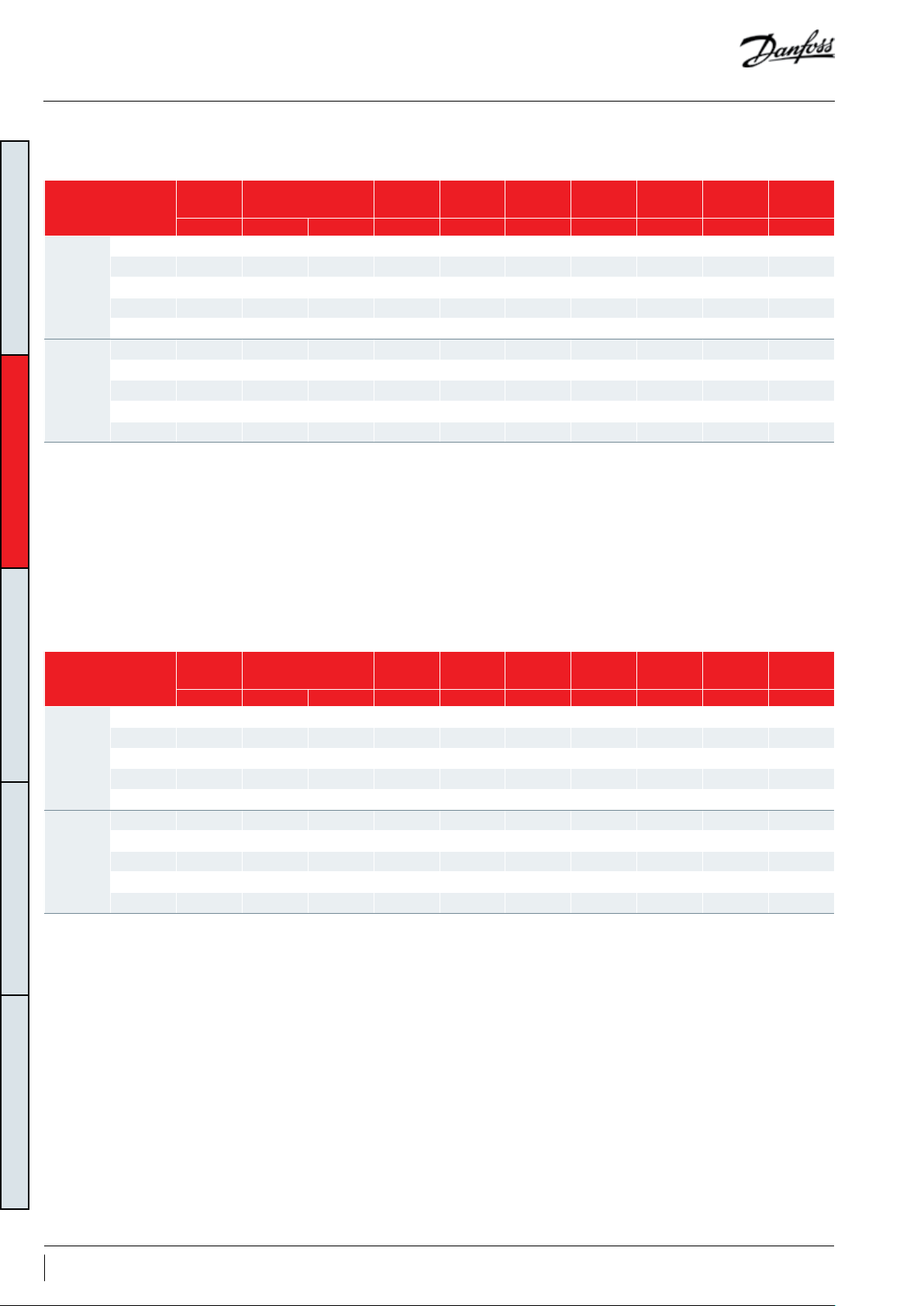
Dimensions
231.9
451
7.2
Single compressors
LLZ013-015-018
95.3
231.9
190.25 - 190.75
1°
Schrader valve
and cover
95.3
GENERAL INFORMATIONSYSTEM DESIGNINTEGRATION INTO SYSTEMORDERING INFORMATION PRODUCT INFORMATION
133
108.8
Schrader
119.3
78.5 - 80.5
Discharge line
Ø1.00" - 14UN (2A)
92 - 94
34°
31°
45°±2°
124.9
suction
106.4
line
sight
glass
190.25 - 190.75
Injection line
Ø1.00" - 14UN (2A)
Suction line
Ø1.25" - 12UN (2A)
478.2
238.4
C
T₁
R
T₃
Ring connect screw terminals
C terminal box type
Sight glass
86.4
374.5
302.2
Mounting grommetTerminal box
1.7
S
T₂
41
29.5
Ø 41
Recommended torque for
mounting bolts: 11 Nm (±1 Nm)
Ø11
5/16" - 18 UNC
self tapping
10 FRCC.PC.039.A1.02
Page 11
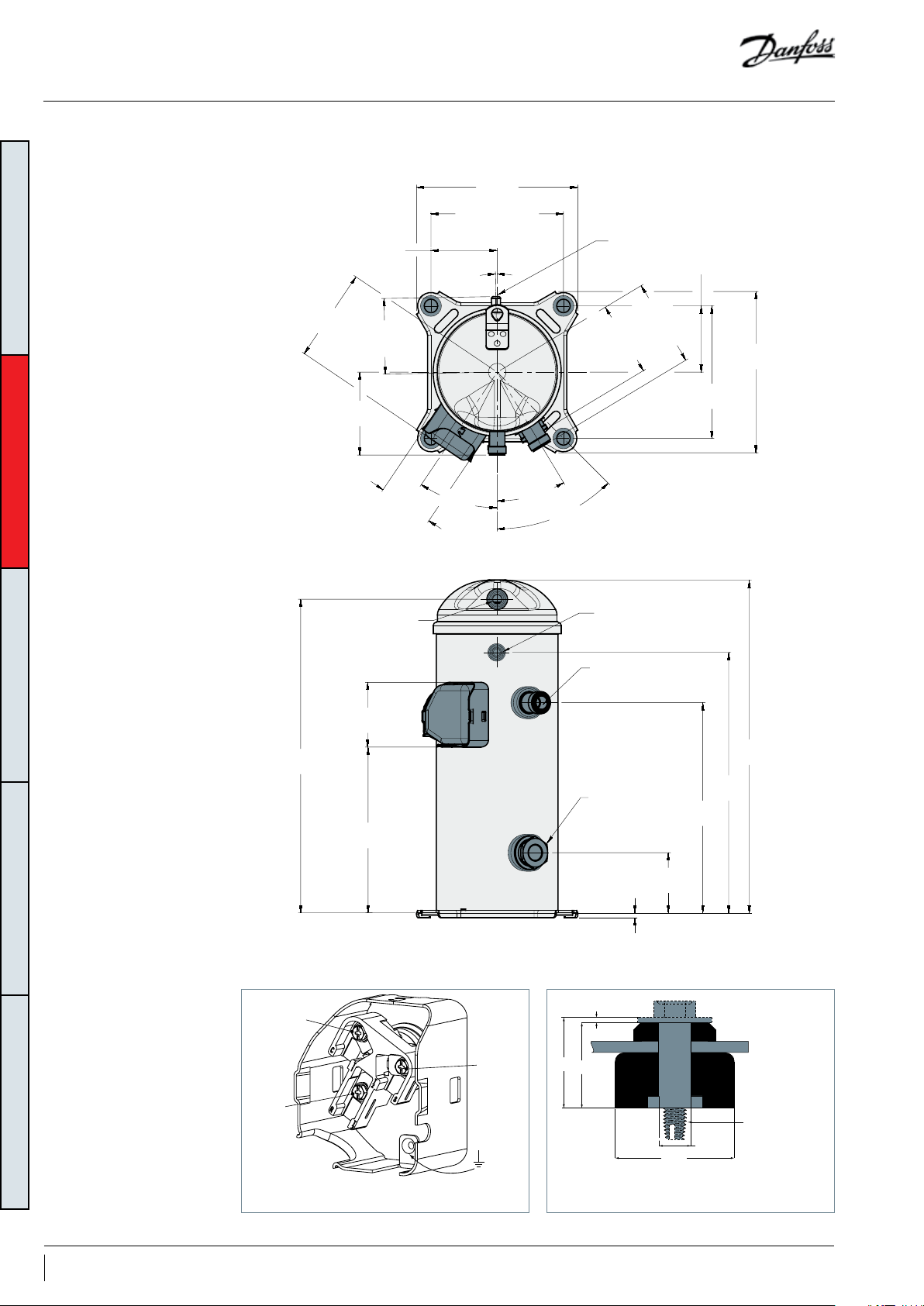
Dimensions
Single compressors
LLZ024
133
119.3
95.25
231.9
190.25-190.75
108.8
4x Ø19.0 - 20.0
106.4
sight
glass
14°±2°
124.9
suction
line
95.25
190.25-
190.75
231.9
GENERAL INFORMATIONSYSTEM DESIGNINTEGRATION INTO SYSTEMORDERING INFORMATION PRODUCT INFORMATION
Discharge line
Ø1.25" - 12UN (2A)
92.0-94.0
505.5
278.4
78.5-80.5
34°
31°
45°±2°
Ø183.14-185.14
73°
Injection line
Ø1.00" - 14UN (2A)
Suction line
Ø1.75" - 12UN (2A)
Sight glass
Schrader valve
and cover
7.2
48.4
532.7
414.5
342.2
126.4
C
T₁
R
T₃
Ring connect screw terminals
C terminal box type
Mounting grommetTerminal box
1.7
S
T₂
41
29.5
Ø 41
Recommended torque for
mounting bolts: 11 Nm (±1 Nm)
Ø11
5/16" - 18 UNC
self tapping
11FRCC.PC.039.A1.02
Page 12
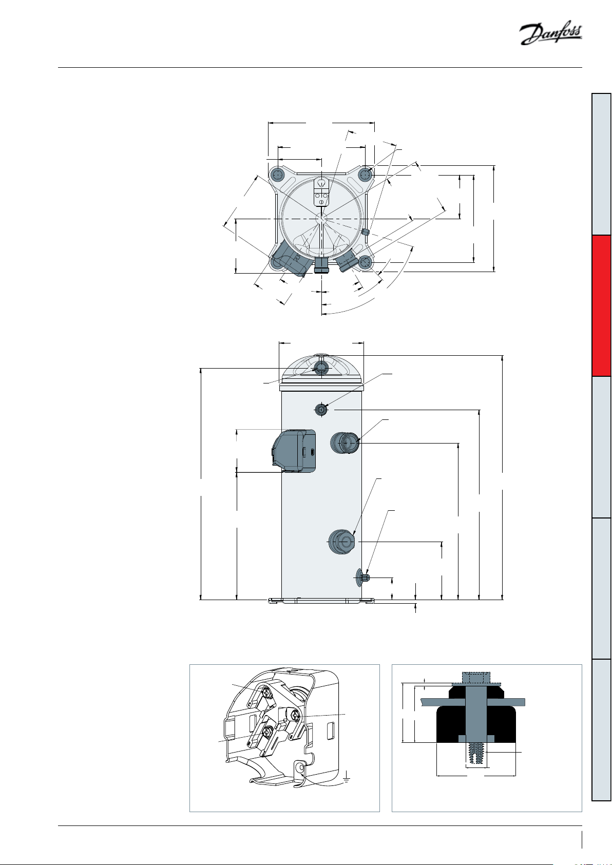
Dimensions
7.2
530.5
231.9
Single compressors
LLZ034
GENERAL INFORMATIONSYSTEM DESIGNINTEGRATION INTO SYSTEMORDERING INFORMATION PRODUCT INFORMATION
133
95.25
190.25 - 190.75
108.8
Schrader
106.4
sight
glass
4x Ø19 - 20
124.9
suction
line
95.25
231.9
190.25 - 190.75
119.3
78.5 - 80.5
Discharge line
Ø1.25" - 14UN (2A)
92 - 94
303.4
34°
183.14 - 185.14
31°
45°±2°
14°±2°
73°
Injection line
Ø1.00" - 14UN (2A)
Suction line
Ø1.75" - 12UN (2A)
Sight glass
Schrader valve
and cover
557.7
439.5
367.2
12 FRCC.PC.039.A1.02
C
T₁
R
T₃
Ring connect screw terminals
C terminal box type
126.4
48.4
Mounting grommetTerminal box
1.7
S
T₂
41
29.5
Ø 41
Recommended torque for
mounting bolts: 11 Nm (±1 Nm)
Ø11
5/16" - 18 UNC
self tapping
Page 13
Dimensions
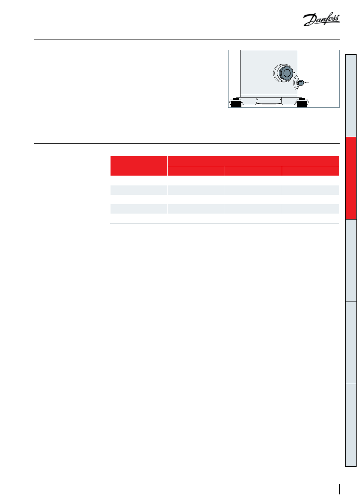
Oil sight glass
Schrader
Suction and discharge
connections
LLZ scroll compressors come equipped with a
threaded oil sight glass with 1"1/8 - 18 UNEF
connection. It can be used for a visual check
of the oil amount and condition or it may be
replaced by an accessory oil management device.
The oil level must be visible in the sight glass
during operation.
The oil ll and drain connection and gauge port
is a 1/4" male are connector incorporating a
schrader valve.
LLZ scroll compressors are factory delivered with rotolock connections only.
Compressor Models
Suction Fitting (in) Discharge Fitting (in) Injection Fitting (in)
LZL013 1"1/4 1" 1"
LL Z015 1"1/4 1" 1"
LLZ018 1"1/4 1" 1"
LLZ024 1"3/4 1"1/4 1"
LLZ034 1"3/4 1"1/4 1"
Rotolock Sizes
Oil sight glass
Schrader valve
and cap
GENERAL INFORMATIONSYSTEM DESIGNINTEGRATION INTO SYSTEMORDERING INFORMATION PRODUCT INFORMATION
13FRCC.PC.039.A1.02
Page 14
Electrical data, connections and wiring
Danfoss scroll compressors LLZ are available in 3 dierent motor voltages as listed below.Motor voltage
GENERAL INFORMATIONSYSTEM DESIGNINTEGRATION INTO SYSTEMORDERING INFORMATION PRODUCT INFORMATION
Motor voltage code Code 2 Code 4 Code 9
Nominal voltage 200-220V-3 ph 380-415V - 3 ph -
50 Hz
Voltage range 180 -242V* 342-457 V
Nominal voltage 208-230V-3 ph 460V - 3 ph 380V -3 ph
60 Hz
Voltage range 187-253V* 414-5 06 V 342-418V
Wiring connections
The maximum allowable voltage imbalance is
2%. Voltage imbalance causes high amperage
over one or several phases, which in turn leads to
% voltage
imbalance
Vavg = Mean voltage of phases 1, 2, 3.
V1-2 = Voltage between phases 1 and 2.
Danfoss scroll compressors LLZ will only
R
= x 100
| Vavg - V1-2 | + | Vavg - V1-3 | + | Vavg - V2-3 |
compress gas while rotating counter-clockwise
(when viewed from the compressor top).
Three-phase motors will start and run in either
direction, depending on the phase angles of
the supplied power. Care must be taken during
installation to ensure that the compressor
operates in the correct direction (see “Phase
sequence and reverse rotation protection”).
The drawings hereafter show electrical terminal
labelling and should be used as a reference
when wiring the compressor. For three phase
applications, the terminals are labelled T1, T2, and
T3. . For single-phase applications the terminals
are labelled C (common), S (start), and R (run).
overheating and possible motor damage. Voltage
imbalance is given by the formula:
2 x Vavg
V1-3 = Voltage between phases 1 and 3.
V2-3 = Voltage between phases 2 and 3.
C
T1
S
T2
R
T3
Ring connect screw terminals
C terminal box type
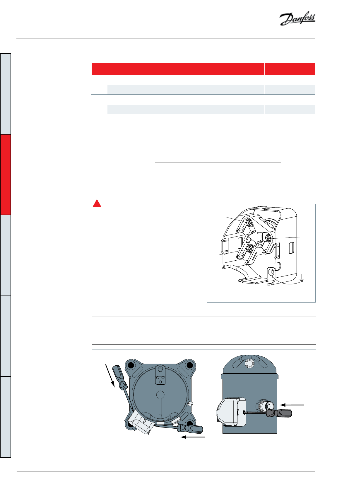
Terminal cover mounting
Terminal cover removal
14 FRCC.PC.039.A1.02
The terminal cover and gasket should be installed
prior to operation of the compressor. Respect the
"up" marking on gasket and cover and ensure
push
push
that the two outside tabs of the cover engage the
terminal box.
push
Page 15

Electrical data, connections and wiring
IP rating
Three phase electrical
characteristics
The compressor terminal box IP rating according to CEI 529 is IP22 for all models. IP ratings is only valid
when correctly sized cable glands of the IP rating is applied.
First numeral, level of protection against contact and foreign objects
2 - Protection against object size over 12.5 mm (ngers of similar)
Second numeral, level of protection against water
2 - Protection against dripping water when tilted up to 15°
The IP rating can be upgraded to IP54 with an accessory kit (see section “Accessories”).
Max. operating
current with
economizer
Winding
resistance
Compressor model
Motor voltage code 2
200-220 V / 3 / 50Hz
208-230 V / 3 / 60Hz
Motor voltage code 4
380-415/3ph/50Hz
460V/3ph/60Hz
Motor voltage code 9
380V/3ph/60Hz
LRA MCC
A A A A Ω
LL Z013 123 .0 25.0 16.4 20.0 0.60
LL Z015 180.0 29.0 18.9 23.0 0.50
LLZ018 184. 0 31.0 24.1 29.4 0.43
LLZ024 190 .0 40.0 28.4 34.7 0.37
LLZ034 250.0 50.0 42.4 44.7 0.29
LL Z013 62.0 12.0 8.0 9.8 2.30
LL Z015 88.5 15. 0 9.8 12.0 1.69
LLZ018 90.0 15.0 11.8 14.4 1.61
LLZ024 95.0 21.0 15. 0 18 .3 1.4 8
LLZ034 150. 0 26.0 19.1 22.7 0.84
LL Z013 81.0 14.0 9.4 11.8 1.49
LL Z015 81.0 17.0 11. 3 14.2 1.49
LLZ018 106.0 20.0 13.7 16. 5 1.13
LLZ024 135 .0 21.0 17.1 19. 4 0.93
LLZ034 155.0 29.6 22.9 25.5 0.63
Max. operating
current
GENERAL INFORMATIONSYSTEM DESIGNINTEGRATION INTO SYSTEMORDERING INFORMATION PRODUCT INFORMATION
15FRCC.PC.039.A1.02
Page 16

Electrical data, connections and wiring
LRA (Locked Rotor Amp)
MCC (Maximum Continuous
Current)
GENERAL INFORMATIONSYSTEM DESIGNINTEGRATION INTO SYSTEMORDERING INFORMATION PRODUCT INFORMATION
Max. operating Current
Winding resistance
Locked Rotor Amp value is the higher average
current as measured on mechanically blocked
compressor tested under nominal voltage. The
LRA value can be used as rough estimation for
The MCC is the current at which the motor
protection trips under maximum load and
low voltage conditions. This MCC value is the
maximum at which the compressor can be
operated in transient conditions and out of
The max. operating current is the current when
the compressors operate at maximum load
conditions and 10% below nominal voltage
(+15°C evaporating temperature and +68°C
Winding resistance is the resistance between
phases at 25°C (resistance value +/- 7%).
Winding resistance is generally low and it
requires adapted tools for precise measurement.
Use a digital ohm-meter, a "4 wires" method and
measure under stabilised ambient temperature.
Winding resistance varies strongly with winding
temperature. If the compressor is stabilised
at a dierent value than 25°C, the measured
resistance must be corrected using the following
formula:
the starting current. However in most cases, the
real starting current will be lower. A soft starter
can be applied to reduce starting current.
the application envelope. Above this value, the
overload or external electronic module will cutout the compressor to protect the motor.
condensing temperature). Max Oper. A can be
used to select cables and contactors. In normal
operation, the compressor current consumption
is always less than the Max Oper. A. value.
a + t
R
= R
tamb
25°C
a + t
t
: reference temperature = 25°C
25°C
t
: temperature during measurement (°C)
amb
R
: winding resistance at 25°C
25°C
R
: winding resistance at tamb
amb
amb
_______
25°C
Coecient a = 234.5
Motor protection
Phase sequence and reverse
rotation protection
Danfoss scroll compressors LLZ are equipped
with an internal line break protector mounted
on the motor windings. The protector is an
automatic reset device, containing a snap action
bimetal switch.
Internal protectors respond to over-current and
overheating. They are designed to interrupt
The compressor will only operate properly in a
single direction. Use a phase meter to establish
the phase orders and connect line phases L1, L2
and L3 to terminals T1, T2 and T3, respectively.
For three-phase compressors, the motor will run
equally well in both directions. Reverse rotation
results in excessive noise; no pressure dierential
between suction and discharge; and suction
line warming rather than immediate cooling. A
Motor current under a variety of fault conditions,
such as failure to start, running overload, and fan
failure.
If the internal overload protector trips out, it must
cool down to about 60°C to reset. Depending on
ambient temperature, this may take up to several
hours.
service technician should be present at initial
start-up to verify that supply power is properly
phased and that compressor and auxiliaries are
rotating in the correct direction.
Phase monitors are required for LLZ compressors.
The selected phase monitor should lock out the
compressor from operation in reverse.
16 FRCC.PC.039.A1.02
Page 17

Approval and certicates
Pressure equipment
directive 97/23/EC
Low voltage directive
2006/95/EC
Machines directive
2006/42/EC
LLZ scroll compressors comply with the following
approvals and certicates.
CE 0062 or CE 0038 or CE0871
(European Directive)
UL
(Underwriters Laboratories)
Other approvals / certicates Contact Danfoss
*LVD compliant without Annex AA
Products LLZ013-034
Refrigerating uids Group 2
Category PED I
Evaluation module no scope
Products LLZ013-034
Declaration of conformity
ref. Low voltage Directive 2006/95/EC
Products LLZ013-034
Manufacturer’s declaration of incorporation ref.
Machines Directive 2006/42/EC
Certicates are listed on the product datasheets:
http://www.danfoss.com/odsg
All LLZ models
All LLZ models
Contact Danfoss
Contact Danfoss
GENERAL INFORMATIONSYSTEM DESIGNINTEGRATION INTO SYSTEMORDERING INFORMATION PRODUCT INFORMATION
Internal free volume
Products Internal free volume at LP side without oil (litre)
LLZ013-015-018 4.74
LLZ024-034 5.95
17FRCC.PC.039.A1.02
Page 18

Design piping
U-trap, as short as possible
U-trap
General requirements Proper piping practices should be employed to:
1. Ensure adequate oil return, even under
minimum load conditions (refrigerant speed,
piping slopes…). For validation tests see section
“Manage oil in the circuit”.
GENERAL INFORMATIONPRODUCT INFORMATIONINTEGRATION INTO SYSTEMORDERING INFORMATION SYSTEM DESIGN
max. 4 m
max. 4 m
g.1
0.5% slope,
4 m/s or more
U-trap, as short as possible
8 to 12 m/s
0.5% slope,
4 m/s or more
Evaporator
To condenser
U-trap
2. Avoid condensed liquid refrigerant from
draining back to the compressor when stopped
(discharge piping upper loop). For validation
tests see section “Manage o cycle migration”.
General recommendations are described in the
gures below:
g. 2
HP
Upper loop
Condenser
LP
3D exibility
3. Piping should be designed with adequate
three-dimensional exibility to avoid excess
vibration. It should not be in contact with the
surrounding structure, unless a proper tubing
mount has been installed. For more information
on noise and vibration, see section on: “Sound
and vibration management”.
18 FRCC.PC.039.A1.02
Page 19

Design compressor mounting
General requirements
Single compressor
requirements
Compressors used in single application must be
mounted with exible grommets
Compressors used in parallel application must be
mounted with rigid mounting spacers onto rails
LLZ compressors are delivered with exible
grommets, accessory mounting kit.
Mounting grommet
1.7
41
29.5
5/16" - 18 UNC
Ø11
Ø 41
Recommended torque for
mounting bolts: 11 Nm (±1 Nm)
self tapping
and the manifold assembly must be mounted
with exible grommets onto frame.
During operation, maximum inclination from the
vertical plane must not exceed 3 degrees.
The grommets must be compressed until contact
between the at washer and the steel mounting
sleeve is established. The required bolt size for
the LLZ013-034 compressors is M8*45mm. This
bolt must be tightened to a torque of 11 Nm.
GENERAL INFORMATIONPRODUCT INFORMATIONINTEGRATION INTO SYSTEMORDERING INFORMATION SYSTEM DESIGN
19FRCC.PC.039.A1.02
Page 20

Manage sound and vibration
Compressor sound
radiation
GENERAL INFORMATIONPRODUCT INFORMATIONINTEGRATION INTO SYSTEMORDERING INFORMATION SYSTEM DESIGN
Typical sounds and vibrations in systems can be
broken down into the following three categories:
• Sound radiation (through air)
• Mechanical vibrations (through parts and
• Gas pulsation (through refrigerant)
The following sections focus on the causes and
methods of mitigation for each of the above
sources.
structure)
For sound radiating from the compressors,
the emission path is air and the sound waves
are travelling directly from the machine in all
directions.
Sound levels are as follows:
• For compressors running alone:
50 Hz 60 Hz
Compressor model
LL Z013 78 8 80 8 12 0Z5052
LL Z015 80 8 83 8 120Z5052
LLZ018 83 10 84 10 120Z505 2
LLZ024 85 10 86 10 120Z5053
LLZ034 85 8 86 8 120Z5 055
Sound power and attenuation are given at ARI LBP conditions, measured in free space
Attenuation given with acoustic hood
Materials are UL approved and RoHS compliant
Sound power
dB(A)
Attenuation
dBA
Sound power
dB(A)
Attenuation
dBA
Acoustic hood
code number
LLZ scroll compressors have a unique discharge
valve design that minimizes stopping noise. This
results in very low shutdown sound.
Note: During compressor shut down, a short
reverse rotation sound is generated. The duration
of this sound depends on pressure dierence at
shut down and should be less than 3 seconds.
This phenomenon has no impact on compressor
reliability.
Mitigations methods:
We can consider two means to reduce
compressors sound radiations:
1. Acoustic hoods are quick and easy to install
and do not increase the overall size of the
compressors to a great extent. Acoustic hoods
are available from Danfoss as accessories. Refer
to table above for sound levels, attenuation and
code numbers.
2. Use of sound-insulation materials on the inside
of unit panels is also an eective means to reduce
radiation.
20 FRCC.PC.039.A1.02
Page 21

Manage sound and vibration
Mechanical vibrations
Gas pulsation
Vibration isolation constitutes the primary
method for controlling structural vibration. LLZ
scroll compressors are designed to produce
minimal vibration during operations. The use of
rubber isolators on the compressor base plate or
on the frame of a manifolded unit is very eective
in reducing vibration being transmitted from the
compressor(s) to the unit. Rubber grommets are
supplied with all LLZ scroll compressors.
Once the supplied rubber grommets have
been properly mounted, vibration transmitted
from the compressor base plate to the unit
are held to a strict minimum. In addition, it is
The LLZ scroll compressors have been designed
and tested to ensure that gas pulsation has
been minimized for the most commonly
encountered refrigeration pressure ratio. On
installations where the pressure ratio lies beyond
the typical range, testing should be conducted
under all expected conditions and operating
congurations to ensure that minimum gas
pulsation is present.
extremely important that the frame supporting
the mounted compressor be of sucient mass
and stiness to help dampen any residual
vibration potentially transmitted to the frame.
The tubing should be designed so as to both
reduce the transmission of vibrations to other
structures and withstand vibration without
incurring any damage. Tubing should also be
designed for three-dimensional exibility. For
more information on piping design, please see
the section entitled “Essential piping design
considerations”.
Mitigations methods:
If an unacceptable level is identied, a discharge
muer with the appropriate resonant volume
and mass can be installed.
GENERAL INFORMATIONPRODUCT INFORMATIONINTEGRATION INTO SYSTEMORDERING INFORMATION SYSTEM DESIGN
21FRCC.PC.039.A1.02
Page 22

Manage operating envelope
Saturated discharge temperature (°C)
Saturated suction temperature (°C)
RGT 18.3°C
SH 20K
LLZ No Injection Operating Envelope (R404A/R507)
-45 -40 -35 -30 -25 -20 -15 -10 -5
5
0
10
15
20
25
30
35
40
45
50
55
60
65
Saturated discharge temperature (°C)
Saturated suction temperature (°C)
RGT 18.3°C
LLZ with economizer Operating Envelope (R404A/R507)
-45 -40 -35 -30 -25 -20 -15 -10 -5
5
0
10
15
20
25
30
35
40
45
50
55
60
65
Requirement
GENERAL INFORMATIONPRODUCT INFORMATIONINTEGRATION INTO SYSTEMORDERING INFORMATION SYSTEM DESIGN
R
The operating envelope for LLZ scroll
compressors is given in the gures below and
Steady-state operation envelope is valid for a
suction superheat high than 5K
guarantees reliable operations of the compressor
for steady-state and operation.
LLZ compressor operating envelop are dierence with refrigerant and with/with out injection. The
detail as following.
LLZ Compressor with R404A/R507, code2/4/9, Non Injection
LLZ Compressor with R404A/R507, code2/4/9, with economizer line
22 FRCC.PC.039.A1.02
Page 23

Saturated discharge temperature (°C)
Saturated suction temperature (°C)
20°C RGT No LI
20°C RGT+LI
30K SH+LI
LLZ Liquid Injection Operating Envelope (R404A/R507)
-45 -40 -35 -30 -25 -20 -15 -10 -5
5
0
10
15
20
25
30
35
40
45
50
55
60
65
Manage operating envelope
LLZ Compressor with R404A/R507, code2/4/9, with liquid injection(LI)
GENERAL INFORMATIONPRODUCT INFORMATIONINTEGRATION INTO SYSTEMORDERING INFORMATION SYSTEM DESIGN
Pressure settings R404A/R507
Working range high side bar(g) 5. 94 -27. 74
Working range low side bar(g) 0.33-3.34
Maximum high pressure safety switch setting bar(g) 29.7
Minimum low pressure safety switch setting bar(g) 0.15
Minimum low pressure pump-down switch setting bar(g) 0.33
R
LP and HP safety switches must never
be bypassed nor delayed and must stop all the
compressors.
HP safety switch must be manual reset
Depending on application operating envelope,
you must dene HP and LP limits within
operating envelope and pressure setting table
above.
For LLZ compressors, the external Discharge
Gas Temperature protection (DGT) is required
if the high and low pressure switch settings do
not protect the compressor against operations
beyond its specic application envelope.
The discharge gas thermostat accessory kit (code
7750009) includes all components required
for installation as shown on the right. DGT
installation must respect below requirements:
When caused low by LP safety switch, limit the
number of auto-restart to maximum 5 times
within 12 hours.
• The thermostat must be attached to the
discharge line within 150 mm from the
compressor discharge port and must be
thermally insulated and tightly xed on the
pipe.
• The DGT should be set to open at a discharge
gas temperature of 135°C.
Thermostat
Discharge line
Insulation
Bracket
23FRCC.PC.039.A1.02
Page 24

Manage operating envelope
Evaluate the risk We consider two types of operating envelope
management:
GENERAL INFORMATIONPRODUCT INFORMATIONINTEGRATION INTO SYSTEMORDERING INFORMATION SYSTEM DESIGN
Basic:
• HP and LP switch
• MOP (Max Operating Pressure) ensured by expansion
device
• Condensing pressure control
• (DGT integrated)
HP switch setting
DGT (integrated)
MOP
LP switch setting
Condensing pressure control
Advanced:
• HP and LP sensor
• Operating envelope limits (permanent and transient)
integrated into control logic
• (DGT integrated)
No additional test are required
24 FRCC.PC.039.A1.02
Page 25

Theory of Injection cycle
Theory of Vapor injection
cycle
Economizer system conguration
The below schematic shows a system
conguration with a heat exchanger acting as an
economizer for economized cycle (12345671).
The economizer is used to provide subcooling
to the refrigerant leaving the condenser before
it enters into the evaporator. This subcooling
process provides an increased capacity gain for
P
P
i
the system. Meanwhile, another small amount of
refrigerant leaving the condenser goes through
the expansion device and is then evaporated and
superheated. The superheated refrigerant is then
injected into the mid-compression cycle of the
compressor and compressed together with the
suction ow. The injected vapour also provides
cooling and therefore lowers the disch arge
temperature.
Economizer cycle 12345671
6
7
1
m+i
5
i
m
4
3
2
h
GENERAL INFORMATIONPRODUCT INFORMATIONINTEGRATION INTO SYSTEMORDERING INFORMATION SYSTEM DESIGN
Theory of liquid injection
cycle
Liquid injection system conguration
The below schematic shows a system
conguration with a liquid injection
cycle(1234561). The liquid refrigerant is injected
into scroll pocket, the injected liquid will ash
and absorb heat from compressed gas and
scroll set then cooling the discharge gas, keep
discharge gas temperature within safe limits.
Liquid injection is achieved by utilization of a
Discharge Temperature Responsive Expansion
Valve. The same valve can be used for all LLZ
models with R404A. The valve can regulates
the injection mass ow according to discharge
temperature.
An additional solenoid valve has to be installed
in case of power shortage to prevent from liquid
injection.
For the liquid injection system to be eective,
a minimum of 5°K sub cooled liquid at the at
the injection valve inlet is required. To prevent
a partial or full blockage at the injection port
caused through shavings, foreign bodies etc a
lter should be installed in the liquid line prior to
the injection valve inlet.
Liquid injection cycle 1234561
25FRCC.PC.039.A1.02
Page 26

Theory of Injection cycle
TREV installation o Recommended TREV : Sporlan
Y1037-1/2-230-3/8ODFX3/8ODF
o Liquid injection special accessories:
• Thermal insulator 1pc
• Rotolock sleeve 1" to 3/8" injection
connection 1pc
• Gasket o-ring 1pc
o Sleeve solder and valve location
GENERAL INFORMATIONPRODUCT INFORMATIONINTEGRATION INTO SYSTEMORDERING INFORMATION SYSTEM DESIGN
Insert nut rst , solder sleeve with valve outlet
pipe (Figure A) ; It is not necessary to disassemble
the TREV when soldering to the connecting lines.
Figure A Rotolock tting
Any of the commonly used types of solders or
brazing materials,e.g., 95-5, Sil-Fos, Easy-Flo,
Phos-Copper, Stay Brite 8 or equivalents may
be used for copper to copper connections. It
is important, however, regardless of the solder
used, to direct the ame away from the valve
body. As an extra precaution, a wet cloth may be
wrapped around the body during the soldering
operation. Screw the nut with compressor
injection tting (Figure A/gureB) ;Valve position
should be 30°to 45°with compressor center axis
,the nut screw torque is 80±10NM.
Figure B Valve location
26 FRCC.PC.039.A1.02
Page 27

Theory of Injection cycle
o Bulb location (Figure C)
• Good thermal contact between the bulb and
discharge line is essential. Before assembly,
make sure the pipe and bulb surface is clean,
remove oil and impurities. We recommend to
add thermal Conductive Adhesive or silver paint
at the contact surface .
• Strapping the sensing bulb as close to the
compressor discharge valve as possible, not to
Figure C Bulb location
exceed 20cm.Strap the center of the bulb with
discharge pipe, the screw force should be taken
care, otherwise the bulb will be deformed, the
setting will be changed.
• The control temperature of the valve may be
slightly higher due to the cooling eects of
ambient temperature on the sensing bulb.
Therefore, insulating the bulb with insulator is
mandatory. Remove the paper surface, align the
cut with clamp, wrap around bulb.
GENERAL INFORMATIONPRODUCT INFORMATIONINTEGRATION INTO SYSTEMORDERING INFORMATION SYSTEM DESIGN
* Others refer to Sporlan SD-168 “Installation & eld service instructions” delivered with valve.
27FRCC.PC.039.A1.02
Page 28

Manage superheat
Requirement
GENERAL INFORMATIONPRODUCT INFORMATIONINTEGRATION INTO SYSTEMORDERING INFORMATION SYSTEM DESIGN
Evaluate the risk
During normal operation, refrigerant enters
the compressor as a superheated vapor. Liquid
ood back occurs when a part of the refrigerant
entering the compressor is still in liquid state.
In steady state conditions,
• suction superheat must be higher than 5K
• Discharge superheat must be higher than 15K
• Oil superheat must be higher than 10K
Discharge temperature sensor must be placed
onto the discharge tting and be insulated.
Oil temperature sensor must be placed between
oil sight glass and compressor baseplate and be
insulated.
Use the tables below in relation with the system
charge and the application to quickly evaluate
the risk and potential tests to perform.
BELOW charge limit ABOVE charge limit
No test or additional safeties required Liquid ood back test
Liquid ood back can cause oil dilution and, in
extreme situations lead to liquid slugging that
can damage compression parts.
In transient conditions,
• Discharge superheat must be higher than 5K
• Oil superheat must be higher than 10K
Charge limit is dened in table below:
Models Refrigerant charge limit (kg)
Single
LLZ013-015-018 4.54
LLZ024-034 7.26
Test, criteria and solutions
Tes t Purpose Test condition Pass criteria Solutions
Liquid ood back testing must be
carried out under expansion valve
threshold operating conditions: a
high pressure ratio and minimum
Liquid ood
back test
Defrost test
Steady-state
Transient
Check liquid
oodback
during defrost
cycle
evaporator load (A).
A
Tests must be carried out with most
unfavorable conditions :
• fan staging,
• compressor staging
• …
Defrost test must be carried out in
the most unfavorable condition (at
0°C evaporating temperature)
Oil superheat>10K
Steady-state discharge
superheat>15K
Oil superheat>10K
Transient discharge superheat >5K
Oil superheat>10K
Transient discharge superheat >5K
1. Check expansion valve selection
and setting
2. Add a suction accumulator*
1. Check expansion valve selection
and setting.
-For Thermostatic expansion valve
(TXV) check bulb position...
-For Electronic expansion valve
(EXV) check measurement chain and
PID....
2. Add a suction accumulator*
In refrigeration system, there are
dierent defrost method, such as
electric method. (for more details
see “Control Logic”).
*Suction accumulator oers protection by trapping the liquid refrigerant upstream from the compressor. The accumulator should be sized at least 50 % of
the total system charge. Suction accumulator dimensions can impact oil return (gas velocity, oil return hole size…), therefore oil return has to be checked
according to section “Manage oil in the circuit”.
28 FRCC.PC.039.A1.02
Page 29

Manage o cycle migration
Requirement
Evaluate the risk
Test, criteria and solutions
R
O -cycle refrigerant migration happens:
• when the compressor is located at the coldest
part of the installation, refrigerant vapor
condenses in the compressor.
• or directly in liquid-phase by gravity.
Amount of liquid refrigerant in the compressors
must not overpass the charge limit (refer to
charge limit table in section “Manage superheat”)
Use the table below in relation with the system
charge (refer to charge limit table in section
“Manage superheat”) and the application to
BELOW cHargE Limit aBOV E cHargE Limit
Non split No test or additional safeties required
Since each installation is unique, no test can fully evaluate o-cycle migration, therefore
Split
the following safeties are required:
• Belt type crankcase heater *
• Liquid Line Solenoid Valve**+ pump-down cycle***
When the compressor starts running again, the
refrigerant diluted in the oil generates poor
lubrication conditions. In extreme situations,
this leads to liquid slugging that can damage
compression parts.
GENERAL INFORMATIONPRODUCT INFORMATIONINTEGRATION INTO SYSTEMORDERING INFORMATION SYSTEM DESIGN
quickly dene necessary safeties to implement
and test to perform:
• Belt type crank case heater *
• Migration test
• (External Non-Return Valve)
Tes t N° Purpose Test condition Pass criteria Solutions
Migration test
Check that
there is no
migration of
refrigerant into
the compressor
(either liquid
or vapour
condensating)
Energize CCH*.
Stabilize the non-running system at
a pressure equivalent to 5°C .
Raise the system pressure
equivalent to 20°C. When saturated
condensing temperature reaches
20°C then start the unit.
Oil temperature sensor must be placed between
oil sight glass and compressor baseplate and be
insulated.
*Crank case heater (CCH)
The blet type sump heaters are designed
to protect the compressor against o-cycle
migration of refrigerant.
Additional heater power or thermal insulation
might be needed in case of ambient temperature
below -5°C and a wind speed above 5m/second.
The heater must be energized whenever all the
When all compressors are idle:
• Check in liquid line sight glass that
there is no liquid refrigerant transfer
• Oil superheat must be >10K during
o-cycle
After compressors has started:
• Oil superheat must remain >10K
It is recommended that the heater be turned on
for a minimum of 12 hours prior to starting the
compressor.
**Liquid line solenoid valve (LLSV)
A LLSV is used to isolate the liquid charge
on the condenser side, thereby preventing
against charge transfer to the compressor
during o -cycles. The quantity of refrigerant
on the low-pressure side of the system can be
further reduced by using a pump-down cycle in
association with the LLSV.
1. Check bulb position, tightness of
expansion device,
2. add LLSV**
3. add pump down cycle***
4. Check Crank case heater eciency
compressors are o.
Crank case heater accessories are available from
Danfoss (see section “Accessories”).
***Pump-down cycle
By decreasing pressure in the sump, pump down:
• evacuates refrigerant from oil
• set the sump saturating pressure much
lower than ambiance temperature and due
Optimum
location area
to that, avoid refrigerant condensation in the
compressor.
Pump-down must be set heigher than 0.33Bar(g)
for R404a.
For more details on pump-down cycle see
section “Control Logic”.
29FRCC.PC.039.A1.02
Page 30

Control logic
T
Safety control logic
requirements
HP switch
LP safety switch
GENERAL INFORMATIONPRODUCT INFORMATIONINTEGRATION INTO SYSTEMORDERING INFORMATION SYSTEM DESIGN
Electronic module (Motor
protection, DGT)
Tripping conditions Re-start conditions
Value Time Value Time
See Pressure settings table
from section “Manage
operating envelope”
Contact M1-M2 opened
Immediate, no delay.
No by- pass
Conditions back to normal.
Switch closed again
Manual reset
Maximum 5 auto reset during
a period of 12 hours, then
manual reset.
Maximum 5 auto reset during
a period of 12 hours, then
manual reset.
Cycle rate limit
requirements
Oil management logic
recommendations
Danfoss requires a minimum compressor running
time of 2 minutes to ensure proper oil return and
sucient motor cooling.
Additionally, compressor service life is based on a
maximum of 12 starts per hour.
~
KA
A1
H
T T
A2
TH
KA
~
A2 A3A1
180 s
In some cases, oil management can be enhanced
by control logic:
• If oil return test failed, a function can be
integrated in control to run all compressors
simultaneously during one minute every hour
in order to boost oil return. Time and delay can
be ne-tuned by oil return test N°1 in section
“Manage oil in the circuit”. During oil boost, pay
special attention to superheat management to
avoid liquid ood back and foaming.
Therefore, to guarantee these 2 requirements,
a three-minute (180- sec) time out is
recommended.
• If after running long time in full load, oil
unbalance appears, then a function can be in
control to stop all compressors in manifold
during one minute every two hours in order
to balance oil between compressors. Time and
delay can be ne-tuned by Oil balancing test
N°2 in section “Manage oil in the circuit”.
Defrost logic
recommendations
30 FRCC.PC.039.A1.02
In refrigeration system applications, there
are dierent defrost methods, such as electric
heating defrost, hot gas bypass defrost, reversible
defrost etc. For the systems which use hot gas
bypass or reversible defrost method, suction
accumulator is necessary as a result of the
possibility of a substantial quantity of liquid
refrigerant remaining in the evaporator.
This liquid refrigerant can then return to the
compressor, either ooding the sump or as
a dynamic liquid slug when the cycle switch
back to normal cooling operations. Sustained
and repeated liquid slugging and ooding can
seriously impair the oil’s ability to lubricate the
compressor bearings. In such cases a suction
accumulator is a must.
Page 31

Control logic
Pump-down logic
recommendations
Pump-down cycle: Once the system has reached
its set point and is about to shut o, the LLSV
on the liquid line closes. The compressor then
pumps the majority of the refrigerant charge into
the high pressure side before the system stops on
the low pressure pump-down switch. This step
reduces the amount of charge on the low side in
order to prevent o-cycle migration.
A pump-down cycle represents one of the most
eective ways to protect against the
o-cycle migration of refrigerant; however it is
only convenient to apply on application with
thermostatic control.
Rack application with pressostatic control can use
timer delay to empty the evaporators before the
stop. Time should be carefully set to not interfere
with the low safety pressure switch.
For low pressure pump-down switch settings,
refer to section “High and low pressure
protection”. For suggested wiring diagrams,
please see section “Wiring diagram”.
Under certain conditions, the internal valve may
not completely seal, and due to the refrigerant
back ow the compressor might restart during
pump-down applications. Repeated short cycling
can result in a compressor breakdown. It is
recommended to install an external magnetic
check valve (such as Danfoss Part No. 120Z5046)
close to the compressor’s discharge connector so
the discharge volume is minimized.
A magnetic check valve is recommended for
this as it oers the best solution regarding
minimal required and maximal pressure drop
over the wide application envelope of the LLZ
scroll compressors. If a Danfoss NRV check valve
is applied it has to be carefully selected for the
specic operation conditions of the individual
system.
Tests for pump down cycle approval:
• As the pump-down switch setting is inside the
application envelope, tests should be carried
out to check unexpected cut-out during
transient conditions (i.e. defrost - cold starting).
When unwanted cut-outs occur, the low
pressure pump-down switch can be delayed. In
this case a low pressure safety switch without
any delay timer is mandatory.
• While the thermostat is o, the number of
pressure switch resets should be limited to
avoid short cycling of the compressor. Use
dedicated wiring and an additional relay which
allows for one shot pump-down.
GENERAL INFORMATIONPRODUCT INFORMATIONINTEGRATION INTO SYSTEMORDERING INFORMATION SYSTEM DESIGN
31FRCC.PC.039.A1.02
Page 32

Provide power supply and electrical protection
Wiring information
GENERAL INFORMATIONPRODUCT INFORMATIONINTEGRATION INTO SYSTEMORDERING INFORMATION SYSTEM DESIGN
Requirements:
• An additional external overload protection is
still advisable for either alarm or manual reset.
For overload setting, take the max current
• Provide separate electrical supply for the
heaters so that they remain energized even
when the machine is out of service (e.g.
seasonal shutdown).
you can face on the application and add
10%. Setting must always be lower than Max
Operating Current (see table…)
The wiring diagrams below are examples for a
safe and reliable compressor wiring:
• HP safety switch and DGT must be wired in the
safety chain. Other safety devices such as LP can
be either hardware or software managed.
The wiring diagrams below are examples for a safe and reliable compressor wiring:
Compressor model LLZ 013 - 015 - 018 - 024 - 034
CONTROL CIRCUIT
KM
F1F1
KA KA
PM
KA
KS
L1 L3 L2
Q1
KM
Control device.............................................TH
Optional short cycle timer (3 mins) .180 s
Control relay.................................................KA
Liquid Line Solenoid valve..................LLSV
Compressor contactor.............................KM
Phase monitor............................................PM
Safety lock out relay...................................KS
Pump-down control low
pressure switch............................................LP
High pressure safety switch..................HPs
Fused disconnect.......................................Q1
Fuses................................................................F1
Compressor motor.......................................M
Discharge gas thermostat....................DGT
A1
KM
KS
LP
KA
A3
180 s
A2
TH
KS
LLSV KS
T1
HPs
DGT
T2
T3
M
Wiring diagram with pump-down cycle
Note:
For LLZ phase monitors are mandatory. The selected phase monitor should lock out the compressor from operation in reverse.
32 FRCC.PC.039.A1.02
Page 33

Reduce moisture in the system
Requirements
Solutions
Excessive air and moisture
• can increase condensing pressure and cause
excessively high discharge temperatures.
• can create acid giving rise to copper platting.
• can destroy the lubricating properties of the oil.
LLZ compressors are delivered with < 100 ppm
moisture level.
To achieve this requirement, a properly sized
and type of drier is required. Important selection
criteria’s include:
• driers water content capacity,
• system refrigeration capacity,
• system refrigerant charge.
All these phenomena can reduce service life
and cause mechanical and electrical compressor
failure.
At the time of commissioning, system moisture
content may be up to 100 ppm. During
operation, the lter drier must reduce this to a
level between 20 and 50 ppm.
For new installations with LLZ compressors with
polyolester oil, Danfoss recommends using the
Danfoss DML (100% molecular sieve) solid core
lter drier.
GENERAL INFORMATIONPRODUCT INFORMATIONSYSTEM DESIGNORDERING INFORMATION INTEGRATION INTO SYSTEM
33FRCC.PC.039.A1.02
Page 34

Assembly line procedure
Compressor storage
Compressor holding
charge
GENERAL INFORMATIONPRODUCT INFORMATIONSYSTEM DESIGNORDERING INFORMATION INTEGRATION INTO SYSTEM
Handling
HEAVY
Store the compressor not exposed to rain,
corrosive or ammable atmosphere between
-35°C and 70°C when charged with nitrogen.
Each compressor is shipped with a nominal dry
nitrogen holding charge between 0.4 and 0.7 bar
and is sealed with elastomer plugs.
R
Respect the following sequence:
• Remove the nitrogen holding charge via the
suction schrader valve to avoid an oil mist blow
out.
R
Compressor handling
LLZ Compressors are provided with a lifting
lug. This lug should always be used to lift the
compressor.
Once the compressor is installed, the lifting
lug should never be used to lift the complete
• Remove the suction plug rst and the discharge
plug afterwards to avoid discharge check valve
gets stuck in open position.
An opened compressor must not be exposed to
air for more than 20 minutes to avoid moisture is
captured by the PVE oil.
installation. The compressor must be handled
with caution in the vertical position, with a
maximum inclination of 15° from vertical.
do not lift
manually
34 FRCC.PC.039.A1.02
Page 35

Assembly line procedure
Piping assembly Good practices for piping assembly is a pre-requisite to ensure compressor service life.
System cleanliness
Circuit contamination possible cause: Requirement:
Brazing and welding oxides During brazing, ow nitrogen through the system
Filings and particles from the removal of burrs in
pipe-work
Moisture and air
Remove any particles and burrs generated by tube
cutting and hole drilling
Use only clean and dehydrated refrigeration grade
copper tubing
Opened compressor must not be exposed to air more
than 20 minutes to avoid moisture captured by POE oil
GENERAL INFORMATIONPRODUCT INFORMATIONSYSTEM DESIGNORDERING INFORMATION INTEGRATION INTO SYSTEM
Brazing procedure:
• Brazing operations must be performed by
qualied personnel.
• Make sure that no electrical wiring is connected
to the compressor.
• To prevent compressor shell and electrical box
overheating, use a heat shield and/or a heatabsorbent compound.
• Clean up connections with degreasing agent
• Flow nitrogen through the compressor.
• Use ux in paste or ux coated brazing rod.
R
Before eventual un-brazing of the
compressor or any system component, the
refrigerant charge must be removed.
• Use brazing rod with a minimum of 5% silver
content.
• It is recommended to use double-tipped torch
using acetylene to ensure a uniform heating of
connection.
• For discharge connections brazing time should
be less than 2 minutes to avoid NRVI damages
if any.
• To enhance the resistance to rust, a varnish on
the connection is recommended.
heat shield
A
C
B
System pressure test and
leak detection
The compressor has been strength tested
and leak proof tested (<3g/year) at the factory.
For system tests:
• Pressurize the system on HP side rst then LP
side.
• Do not exceed the following pressures:
• Always use an inert gas such as Nitrogen or
Helium.
Maximum compressor test pressures
Maximum compressor test pressure high side (HP) 31.1 bar (g)
Maximum compressor test pressure low side (LP) 31.1 bar (g)
35FRCC.PC.039.A1.02
Page 36

Assembly line procedure
Vacuum evacuation and
moisture removal
Refrigerant charging
GENERAL INFORMATIONPRODUCT INFORMATIONSYSTEM DESIGNORDERING INFORMATION INTEGRATION INTO SYSTEM
Dielectric strength and
insulation resistance tests
Requirements:
• Never use the compressor to evacuate the
system.
• Connect a vacuum pump to both the LP and HP
sides.
• Evacuate the system to a pressure of 500 μm Hg
(0.67 mbar) absolute.
R
Initial charge:
• For the initial charge, the compressor must not
run.
• Charge refrigerant as close as possible to the
nominal system charge.
• This initial charging operation must be done in
liquid phase between the condenser outlet and
the lter drier.
The tests are performed on each compressor at
the factory between each phase and ground.
• Dielectric strength test is done with a high
potential voltage (hi-pot) of 2Un +1000V AC
at least, and leakage current must be less than
5 mA. Additional tests of this type are not
recommended as it may reduce motor lifetime.
Nevertheless, if such a test is necessary, it must
be performed at a lower voltage.
Recommendations:
• Energized heaters improve moisture removal.
• Alternate vacuum phases and break vacuum.
with Nitrogen to improve moisture removal.
For more detailed information see “Vacuum
pump-down and dehydration procedure”
TI-026-0302.
If needed, a complement of charge can be done:
• In liquid phase while compressor is running by
slowly throttling liquid in.
• On the low pressure side, as far away as possible
from the compressor suction connection.
• Never bypass safety low pressure switch.
For more detailed information see
“Recommended refrigerant system charging
practice“ FRCC.EN.050.
• Insulation resistance is measured with a 500 V
DC megohm tester and must be higher than 1
megohm.
• The presence of refrigerant around the
motor windings will result in lower resistance
values to ground and higher leakage current
readings. Such readings do not indicate a faulty
compressor. To prevent this, the system can be
rst operated briey to distribute refrigerant.
Do not use a megohm meter nor apply
R
power to the compressor while it is under
vacuum as this may cause internal damage.
36 FRCC.PC.039.A1.02
Page 37

Commissioning
Preliminary check
Initial start-up
System monitoring
Check electrical power supply:
• Phase order: For LLZ compressors equipped
with an electronic module, reverse rotation will
be automatically detected. For more details refer
to section “Motor protection”.
• Surface sump heaters must be energized at least
6 hours in advance to remove refrigerant.
• A quicker start-up is possible by “jogging” the
compressor to evacuate refrigerant. Start the
The system must be monitored after initial
startup for a minimum of 60 minutes to ensure
proper operating characteristics such as:
• Correct superheat and subcooling.
• Current draw of individual compressors within
acceptable values (max operating current).
• No abnormal vibrations and noise.
• Correct oil level.
• Voltage and voltage unbalance within tolerance:
For more details refer to section “Motor voltage”.
compressor for 1 second, then wait for 1 to 2
minutes. After 3 or 4 jogs the compressor can
be started. This operation must be repeated for
each compressor individually.
If Oil Top-up is needed, it must be done while the
compressor is idle. Use the schrader connector
or any other accessible connector on the
compressor suction line. Always use original
Danfoss POE oil 160SZ from new cans.
For more detailed information see “Lubricants
lling in instructions for Danfoss Commercial
Compressors” TI 2-025-0402.
GENERAL INFORMATIONPRODUCT INFORMATIONSYSTEM DESIGNORDERING INFORMATION INTEGRATION INTO SYSTEM
37FRCC.PC.039.A1.02
Page 38

Dismantle and disposal
GENERAL INFORMATIONPRODUCT INFORMATIONSYSTEM DESIGNORDERING INFORMATION INTEGRATION INTO SYSTEM
Danfoss recommends that compressors and compressor oil should be recycled by a
suitable company at its site.
38 FRCC.PC.039.A1.02
Page 39

Packaging
Single pack
Industrial pack
Compressors are packed individually in a
cardboard box. They can be ordered in any
quantity. Minimum ordering quantity = 1.
Compressor model
LL Z013 116 9 965 730 460
LL Z015 1169 965 718 460
LLZ018 1169 965 718 468
LLZ024 116 9 965 775 495
LLZ034 1169 965 817 544
Note : Here including 9 single pack compressors
Length
(mm)
Compressors are not packed individually but
are shipped all together on one pallet. They
can be ordered in quantities of full pallets only,
Compressor model Nbr*
As far as possible, Danfoss will ship the boxes on
full pallets of 9 compressors according below
table.
Width
(mm)
Height
(mm)
multiples of 12 compressors, according below
table.
Length
(mm)
Width
(mm)
Height
(mm)
Gross
weight
(kg)
Gross
weight
(kg)
Static
stacking
pallets
GENERAL INFORMATIONPRODUCT INFORMATIONSYSTEM DESIGNINTEGRATION INTO SYSTEMORDERING INFORMATION
LL Z013 12 1170 815 665 538 4
LL Z015 12 1170 815 750 538 4
LLZ018 12 1170 815 750 550 4
LLZ024 12 1170 815 720 586 4
LLZ034 12 1170 815 817 651 4
39FRCC.PC.039.A1.02
Page 40

Ordering codes
Compressor code numbers
Single pack
GENERAL INFORMATIONPRODUCT INFORMATIONSYSTEM DESIGNINTEGRATION INTO SYSTEMORDERING INFORMATION
Compressor
model
LL Z013 T Q 9 121L9519 121L9517 121L9531
LL Z015 T Q 9 121L9515 121L9513 121L9529
LLZ018 T Q 9 121L9511 121L9509 121L9527
LLz024 T Q 9 121L9507 121L9505 121L9525
LLZ034 T Q 9 121L9523* 121L9521 121L9533*
Note: These codes are preliminary
Model
Variation
Danfoss scroll compressors LLZ can be ordered in
either industrial packs or in single packs. Please
Connections Feature
200-230/3/50
208-230/3/60
use the code numbers from below tables for
ordering.
Code no.
2 4 9
380-415/3/50
460/3/60
380-400/3/60
Industrial pack
Code no.
Compressor
model
LL Z013 T Q 9 121L9518 121L9516 121L9530
LL Z015 T Q 9 121L9514 121L9512 121L9528
LLZ018 T Q 9 121L9510 121L9508 121L9526
LLz024 T Q 9 121L9506 121L9504 121L9524
LLZ034 T Q 9 121L9522* 121L9520 121L9532*
Note: These codes are preliminary
Model
Variation
Connections Feature
2 4 9
200-230/3/50
208-230/3/60
380-415/3/50
460/3/60
380-400/3/60
40 FRCC.PC.039.A1.02
Page 41

Accessories
Crankcase heater
Typ e Code No Description Application Packaging
120Z5040 Belt type crankcase heater, 70 W, 240 V, UL, CE mark
120Z5041 Belt type crankcase heater, 70 W, 400/460 V, UL, CE mark Multipack 4
120Z5042 Belt type crankcase heater, 70 W, 575 V, UL, CE mark Multipack 4
120Z0059 Belt type crankcase heater, 65 W, 230 V, UL, CE mark Multipack 6
120Z0060 Belt type crankcase heater, 65 W, 400 V, UL, CE mark Multipack 6
All models
Multipack 4
Discharge temperature protection
Typ e Code No Description Application Packaging
7750009 Discharge thermostat kit All models Multipack 10
7973008 Discharge thermostat kit All models Industry pack 50
Magnetic discharge non return valve
Pack
Size
GENERAL INFORMATIONPRODUCT INFORMATIONSYSTEM DESIGNINTEGRATION INTO SYSTEMORDERING INFORMATION
Pack
Size
Typ e Code No Description Application Packaging
120Z5046 Magnetic discharge non return valve All models Multipack 6
Lubricant
Typ e Code No Description Application Packaging
120Z5035 PVE lubricant, (0.95 litre can) All models Multipack 1
Pack
Size
Pack
Size
41FRCC.PC.039.A1.02
Page 42

Accessories
Mounting kit
Typ e Code No Description Application Packaging
Mounting kit for 1 scroll compressor including 4
grommets, 4 sleeves, 4 bolts, 4 washers, rotolock
GENERAL INFORMATIONPRODUCT INFORMATIONSYSTEM DESIGNINTEGRATION INTO SYSTEMORDERING INFORMATION
120Z0629
120Z0630
connection kit for suction, discharge, economizer
tting and Liquid injection tting for 1 scroll
compressor including 3 Teon seals, 2 nuts, 3 sleeves,
1thermal insulator.
Mounting kit for 1 scroll compressor including 4
grommets, 4 sleeves, 4 bolts, 4 washers, rotolock
connection kit for suction,discharge, economizer
tting and Liquid injection tting for 1 scroll
compressor including 3 Teon seals, 2 nuts, 3 sleeves,
1thermal insulator.
LLZ013/015/018 single 1
LLZ024/034 single 1
Mounting hardware
Typ e Code No Description Application Packaging
120 Z5 017 Mounting grommet All models Single Pack 1
120Z5014 Mounting sleeve All models Single Pack 1
120Z5031 Mounting kit, including 1 bolt, 1 sleeve, 1 washer All models Single Pack 1
120Z5064
Mounting kit for 1 scroll compressor including 4
grommets, 4 sleeves, 4 bolts, 4 washers
All models Single Pack 1
Pack
Size
Pack
Size
Acoustic hood
Typ e Code No Description Application Packaging
120Z5052 Acoustic hood for scroll compressor LL Z013-015- 018 Single pack 1
120Z5053 Acoustic hood for scroll compressor LLZ024 Single pack 1
120Z5055 Acoustic hood for scroll compressor LLZ034 Single pack 1
Pack
Size
42 FRCC.PC.039.A1.02
Page 43

Accessories
Terminal box
Typ e Code No Description Application Packaging
120Z5018 Square terminal box (C & Q version) C and Q version Multipack 10
IP54 upgrade kit
Typ e Code No Description Application Packaging
118 U0 057 IP54 upgrade kit All models Multipack 6
Pack
Size
GENERAL INFORMATIONPRODUCT INFORMATIONSYSTEM DESIGNINTEGRATION INTO SYSTEMORDERING INFORMATION
Pack
Size
43FRCC.PC.039.A1.02
Page 44

Danfoss Commercial Compressors
Danfoss Inverter Scrolls
is a worldwide manufacturer of compressors and condensing units for refrigeration and HVAC applications. With a wide range
of high quality and innovative products we help your company to find the best possible energy efficient solution that respects
the environment and reduces total life cycle costs.
We have 40 years of experience within the development of hermetic compressors which has brought us amongst the global
leaders in our business, and positioned us as distinct variable speed technology specialists. Today we operate from engineering
and manufacturing facilities spanning across three continents.
Danfoss Turbocor Compressors
Danfoss Scrolls
Danfoss Optyma Condensing Units
Danfoss Maneurop Reciprocating Compressors
Danfoss Light Commercial Refrigeration
Compressors
Our products can be found in a variety of applications such as rooftops, chillers, residential air conditioners,
heatpumps, coldrooms, supermarkets, milk tank cooling and industrial cooling processes.
http://cc.danfoss.com
Danfoss Commercial Compressors, BP 331, 01603 Trévoux Cedex, France | +334 74 00 28 29
FRCC.PC.039.A1.02 © Danfoss | DCS (CC) | 2016.06
 Loading...