

Page 1
Data Sheet
Liquid level switch
Type LLS 4000 and LLS 4000U
Compact, cost-ecient, and reliable switch for liquid level measurements
The LLS 4000/4000U liquid level switch is
designed to detect the state (gas or liquid) of
the refrigerant in front of the sensing head,
while installed in a wide range of refrigeration
applications.
The LLS level switch comes in 2 variants, LLS
4000 and LLS 4000U. They are identical except
for the connector thread interface to the
system. The LLS 4000 is provided with G
thread, while the LLS 4000U is provided with
3
NPT
⁄4” thread.
3
⁄4”
The LLS 4000/4000U liquid level switch is based
on the proven reectometry measuring
technology (microwave level measurement)
adapted specically for the new LLS
4000/4000U switch.
LLS 4000/4000U liquid level switches can be
used to control the liquid level of many
dierent refrigerants in vessels, accumulators,
receivers, standpipes, etc. The switches are
normally installed in a pair of two, controlling
the upper liquid level and the lower liquid level.
The level switch includes a relay that switches
by change in refrigerant state. The on site
conguration of the LLS allows the normally
open/closed relay setting depending on the
desired correlation.
For SIL applications a SIL2 version is available
with blocked conguration (not congurable).
All conguration and readings from the LLS
switch are performed through Bluetooth and a
downloadable special Danfoss app.
AI323832972563en-000401
Page 2
Liquid level switch, type LLS 4000 and LLS 4000U
Features
• Plug and play liquid level switch
• Easy installation and minimum or no need for conguration
• SIL design with redundancy on microprocessor and relay
• Convenient communication with all units via Bluetooth and a Danfoss app
• SIL2 compliant version
• Two commonly used connection variants
• Maintenance free
• Replacement of electronic part without removing mechanical part (not applicable for SIL2 devices)
• Applicable for ammonia and commonly used H(C)FCs
• Applicable for R1234ze(E) with POE oils (miscible) or oil free systems
• Applicable for refrigerant oils in Ammonia and H(C)FC systems with a refrigerant gas temperature up to max. 80 °C
• For other medias and mixed medias, please contact Danfoss
• Well proven reectometry measuring principle
• Conforms to: Telecommunications Directive RED 2014/53 EU. Low voltage directive 2014/35/EU. EMC directive
2014/30/EU. ROHS 2011/65/EU
• Approvals: SIL2, FCC, IC, EAC, UA, CMIIT, ANATEL, NBTC CRN
© Danfoss | Climate Solutions | 2022.04 AI323832972563en-000401 | 2
Page 3
Liquid level switch, type LLS 4000 and LLS 4000U
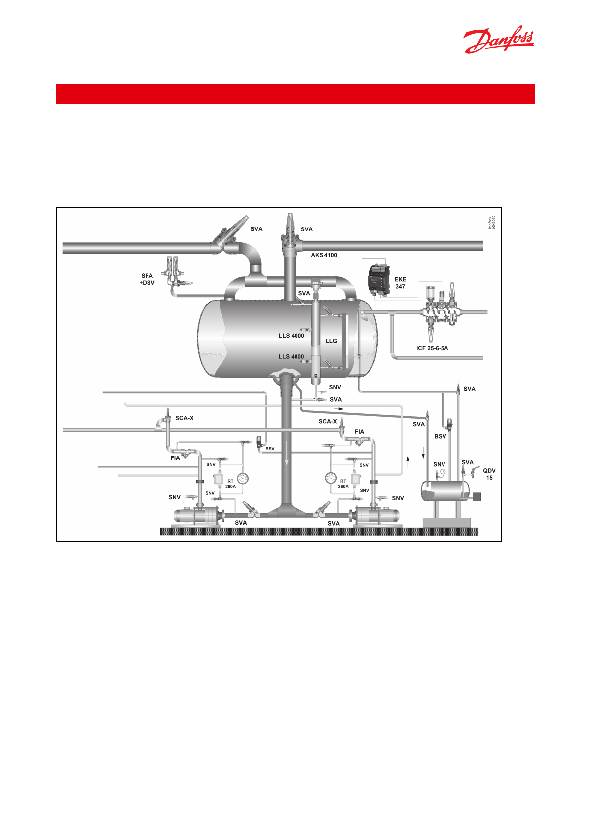
Applications
To control if a liquid level is within predened allowed limits, two LLS 4000 are installed in an upper and a lower limit
position respectively. By this setup the liquid level is between the two level switches and the lower switch will sense
liquid, while the upper will sense gas.
In case the liquid level moves outside the limits, one of the switches will sense opposite and switch the built-in relay.
This relay switch function should be used for alarm settings. This is made easy when connected to the system PLC.
Figure 1: LLS locations
NOTE:
The LLS can be used wherever liquid levels of selected refrigerants and refrigerant oils must be controlled.
© Danfoss | Climate Solutions | 2022.04 AI323832972563en-000401 | 3
Page 4
ABC
Upper LLS 4000/U
Lower LLS 4000/U
Liq. Level
A B
Danfoss
60L9031
ABWith liquid
Without liquid
Liquid level switch, type LLS 4000 and LLS 4000U
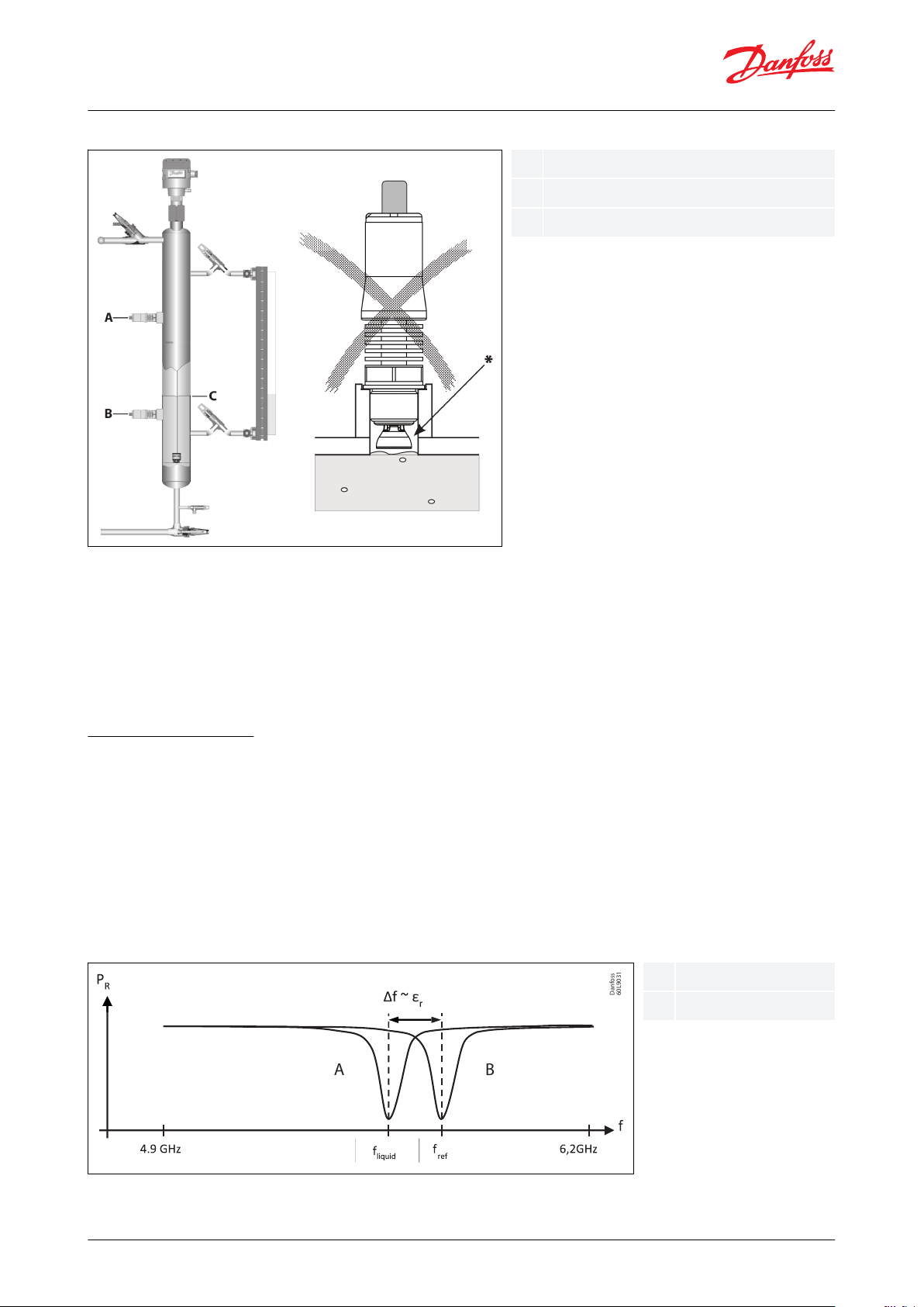
Figure 2: LLS orientation
NOTE:
Horizontal installation recommended. Vertical or inclined installation not recommended: * Risk of Gas Pockets
The LLS comes in two versions:
• A standard version, which is applicable for most refrigeration or processing plants, and is fully congurable
regarding type of liquid and relay setting.
• A SIL2 version applicable for SIL compliant process plants. This version is non-congurable regarding relay setting
(see Congurable parameters) and is intended specic as the upper level switch.
Measuring principle
The measurement principle of the LLS is based on reectometry with a 4.8 GHz to 6.4 GHz linear sweep (Microwave
switch technology). The reected signal is characterized by a resonance frequency.
The resonance frequency in air is taken as a reference (f
the resonance frequency is shifting to a lower frequency. This is due to the change of the dielectric constant of the
medium.
The point level switch monitors the resonance frequency and indicates whether the sensing element is surrounded
by liquid or gas. The gure below shows the reference frequency with air (dielectric constant εr=1) in front of the
sensing element and with a liquid dielectric constant εr>1.35.
Figure 3: Reference frequency
). When the sensing element is in contact with the liquid,
ref
© Danfoss | Climate Solutions | 2022.04 AI323832972563en-000401 | 4
Page 5
Media
Saturation temperature range
Ammonia and listed H(C)FCs and HFOs.
NOTE: For other medias and mixed medias, please contact
Danfoss.
R717 (Ammonia)
-50 °C – +105 °C (-58 °F – +221 °F)
R22 (HCFC)
-50 °C – +86 °C (-58 °F – +187 °F)
R507A (HCFC)
-50 °C – +60 °C (-58 °F – +140 °F)
R134a (HFC)
-50 °C – +91 °C (-58 °F – +196 °F)
R404A (HFC)
-50 °C – +63 °C (-58 °F – +145 °F)
R407A (HFC)
-50 °C – +72 °C (-58 °F – +162 °F)
R410A (HFC)
-50 °C – +61 °C (-58 °F – +142 °F)
R513A (HFC)
-50 °C – +83 °C (-58 °F – +181 °F)
R1234ze(E) (HFO)
(1)
-50 °C – +85 °C (-58 °F – +185 °F)
PAO (Oil)
(2)
Max 5000 cP and +120 °C (Max 5000 cP and +248 °F)
POE (Oil)
(2)
Max 5000 cP and +120 °C (Max 5000 cP and +248 °F)
Mineral (Oil)
(2)
Max 5000 cP and +120 °C (Max 5000 cP and +248 °F)
Liquid level switch, type LLS 4000 and LLS 4000U
Media
Refrigerants
Table 1: Approved media
(1)
(1)
R1234ze(E) with POE oils (miscible)
R1234ze(E) with POE oils (miscible)
(2)
(2)
When detecting oils in Ammonia, H(C)FC and HFO systems, the refrigerant gas temperature above the oil must be lower than 80 °C
When detecting oils in Ammonia, H(C)FC and HFO systems, the refrigerant gas temperature above the oil must be lower than 80 °C
New refrigerants
Danfoss products are continually evaluated for use with new refrigerants depending on market requirements.
When a refrigerant is approved for use by Danfoss, it is added to the relevant portfolio, and the R number of the
refrigerant (e.g. R513A) will be added to the technical data of the code number. Therefore, products for specic
refrigerants are best checked at store.danfoss.com/en/, or by contacting your local Danfoss representative.
© Danfoss | Climate Solutions | 2022.04 AI323832972563en-000401 | 5
Page 6

Features
Specications
Supply
24 V DC +/-25%, 80 mA
Standard power supply of type: SELV (Safety Extra Low Voltage) with current limit of max. 8A.
Relay (Solid state)
Max 30 V DC, 200 mA
Same power supply as to supply can be used.
Observe: In applications with request for SIL2, another separate SELV power supply may be needed.
Min. cycles: 1.000.000
Default delay between detection and relay switching:
PV02: 1 seconds
PV03: 2 seconds
Product Version number can be found on product label. See Figure 9: Nameplate
Actual delay highly inuenced by media viscosity and shall be validated before commissioning.
Overvoltage category
Category II for supply and output
Electrical connection
M12 (4 pins) male on the device
Measuring technology
Microwave reectometry (Not TLPR category)
Communication option
Bluetooth comply to ETSI EN 300 328
Features
Specications
Max. medium viscosity
5000 cP (Un-detection is delayed up to 20 seconds)
Max. working pressure
140 bar (2030 psi)
Ambient temperature range
-40 °C – 65 °C (-40 °F – 149 °F)
Medium temperature range
-50 °C – 120 °C (-58 °F – 248 °F)
Observe restrictions on saturation temperature for approved medias
Operating environment
Pollution degree 3, altitude 2000 max., outdoor use
Relative humidity RH4 to RH99 % (IEC 60721-3-4: 1995 Class 4K4)
Connection type
G ¾” or NPT ¾”
Weight
350 g (0.77 lb)
Enclosure rating
IP 66 / IP 67
IEC 60529: 1989 + A1: 1999 + A2: 2013
NEMA 250: 4X
Housing material (electronics)
Transparent and UV resistant. Compliance with IEC 60695-11-10, UL 94 HB
Housing material (mechanics)
Stainless Steel 316L
Vibration resistance
Long term random 7,54 g RMS (Curve A, IEC 60068-2-64)
Level on pipes and brackets in direct and immediate vicinity of motors, compressors etc
Resonance frequency
600 – 650 Hz
Liquid level switch, type LLS 4000 and LLS 4000U
Product specication
Electrical data
Table 2: Electrical data
Mechanical data
Table 3: Mechanical data
© Danfoss | Climate Solutions | 2022.04 AI323832972563en-000401 | 6
Page 7

3
9
7
2
5
4
6
6
8
1
Pos
Item
Material
Qty.
(1)
1
Housing
Cast Iron, zinc chromated, EN-GJS-400-18-LT
1
2
LLS 4000/U
Stainless Steel
1
3
Top cover
Cast Iron, zinc chromated, EN-GJS-400-18-LT
1
4
Alu gasket
Aluminium
2
5
Plug
Stainless Steel
1
6
Flange bolts
Stainless steel, A2-70 (DIN 267-11) / ASTM A-276
8
7
Gasket
Fiber, non asbestos
1
8
Flange gasket
Fiber, non asbestos
2
9
Top cover bolts
Stainless steel, A2-70 (DIN 267-11) / ASTM A-276
4
Pressure range
AKS 38 housing is designed for a max. working pressure of 28 barg / 406
psig
Temperature range
-50 °C – 65 °C / -58 °F – 149 °F
Red
White
Green
Black
1
24 V DC
24 V DC
*A
Liquid level switch, type LLS 4000 and LLS 4000U
LLS 4000 Retrot AKS 38 kit
Figure 4: Material AKS 38 Retrot housing
Table 4: Material/Technical data AKS 38 Retrot housing
(1)
(1)
QTY included in LLS 4000 Retrot AKS 38 kit
QTY included in LLS 4000 Retrot AKS 38 kit
Wiring diagram
Figure 5: Wiring diagram
NOTE:
*A. Coil voltage must match supply voltage
© Danfoss | Climate Solutions | 2022.04 AI323832972563en-000401 | 7
Page 8

LLS 4000
LLS 4000U NPT ¾”
G ¾”
Weld
connector
25 mm
1 in
min.
Ø30 mm min.
No reduction
45 mm
1.8 in
max.
Area where insulation
is allowed, if media
temperature is less than
ambient temperature
Liquid level switch, type LLS 4000 and LLS 4000U
NOTE:
For ON/OFF level control with 1 x LLS 4000 an externally time delay may be used. The time delay shall be set with
care and provide a dierential NOT higher than 50 – 75 mm under all operating conditions.
Connection types
Beside the two versions the LLS also comes with two dierent thread types, LLS 4000 and LLS 4000U. They are
identical except for the connector thread for installation to the system. The LLS 4000 is provided with G
while the LLS 4000U is provided with NPT
For connection to the actual part of the system appropriate weld connectors are needed. Danfoss oers weld
connectors for both G and NPT
Figure 6: LLS 4000/4000U installation
3
⁄4” thread as accessory. Please note geometric restrictions below.
3
⁄4” thread.
3
⁄4” thread,
Electrical installation/connection
The LLS 4000 level switch must be installed as one unit (mechanical and electrical assembled) without disassembly
to avoid the need for recalibration.
For powering the device, a low power source (LPS) must be used with safety extra low voltage output (SELV) and
current limited to 8A maximum.
After connecting the M12 female cable to the power supply and relay circuit the M12 plug can be installed on the
M12 male connector and the power can be switched on.
At this stage the green light LED will turn on and be visible through the transparent housing (see Figure 8).
The LLS is now ready for conguration via the Danfoss Bluetooth app (see Congurable parameters).
Danfoss M12 cables (ordered separately)
M12 straight cable female x 2 meter,
M12 straight cable female x 8 meter
(M12 angle cable are not recommended)
© Danfoss | Climate Solutions | 2022.04 AI323832972563en-000401 | 8
Page 9

1
2
3
4
+ Red
- White
Green
Black
Relay: 30 V DC
200 mA
24 V DC
+/- 25%
Red light LED
Yellow light LED
Green light LED
Liquid level switch, type LLS 4000 and LLS 4000U
Figure 7: M12 cable connection
LED light indicators
Figure 8: LED position
There are three LED indicators inside the LLS 4000 behind the transparent cover.
• Green indicates the state of power to the switch
◦ If ashing: Bluetooth connection is established
• Yellow indicates if liquid is in front of switch
• Red indicates if alarm is present
Congurable parameters
The set-up of the LLS 4000 is easy and simple, since only few parameters in the LLS software are congurable.
These are:
• Media type - Ammonia, HFC, HCFC; HFO or Oil. Factory default: Ammonia
• Relay NO (normally open when no liquid) or NC (normally closed when no liquid). Factory default: Normally closed
For plants where factory defaults are valid, the installation and set-up is simply Plug & play.
Table 5 shows possible congurations, relay state for given conguration/liquid level and LED indications.
© Danfoss | Climate Solutions | 2022.04 AI323832972563en-000401 | 9
Page 10

Level
Open at no Liquid
(Normally Open)
(1)
Closed at no Liquid
(Normally Closed)
(1)
Voltage con‐
nected
Level detec‐
tion
LLS Fault
Green LED
Yellow LED
Red LED
High Level sensor
SIL2 fixed
configuration
(2)
Low Level sensor
(3)
Voltage supply outside spec.
LLS 4000/4000U fault
(4)
(5)
Liquid level switch, type LLS 4000 and LLS 4000U
Table 5: Conguration chart
(1)
(1)
Conguration dependent. Non-SIL2 fully congurable. SIL2 xed conguration and only applicable for High Level sensor
Conguration dependent. Non-SIL2 fully congurable. SIL2 xed conguration and only applicable for High Level sensor
(2)
(2)
Not recommended in these applications: A High Level Alarm may not be registered at a power failure
Not recommended in these applications: A High Level Alarm may not be registered at a power failure
(3)
(3)
Not recommended in these applications: A Low Level Alarm may not be registered at a power failure
Not recommended in these applications: A Low Level Alarm may not be registered at a power failure
(4)
(4)
For failure types please connect the device to the Bluetooth App, enter fault state mode, and read the failure type
For failure types please connect the device to the Bluetooth App, enter fault state mode, and read the failure type
(5)
(5)
Fault can be detected at any detected level, ie. two or all three lights on
Fault can be detected at any detected level, ie. two or all three lights on
Maintenance/service & calibration precautions
NOTE:
The LLS 4000 is considered maintenance free, but there are a few precautions that needs attention.
The ns shall be kept free of dirt, dust, paint and oil etc. that potentially reduces the thermal heat transfer from the
ns to the air.
For LLS cleaning use soft cloth dry or wet or compressed air.
If the electronic part is separated from the mechanical part during installation, service or maintenance, the ingress
of any foreign substances to the electronic or mechanical part shall be avoided.
Generally the separating of electronic and mechanical parts should be avoided due to calibration, and the mixing of
mechanical and electronic parts from dierent switches must be avoided. In case of the incident mixing of
mechanical and electronic parts from dierent switches, subsequent recalibration might be required.
Prior to calibration the following must be ensured:
The LLS must be out of liquid state (in gas phase), otherwise the calibration might end up incorrect.
This can be secured by either emptying the actual vessel or uninstall the LLS to ambient air.
While in “dry” surroundings, connect power to the LLS switch and perform the calibration.
The Danfoss LLS app includes the calibration possibility. Calibration is not applicable for devices congured for SIL2
devices).
Ice build-up on the LLS switch reduces the accessibility for the Bluetooth connection.
• 10 cm icecap reduces the distance from app device to the LLS to 1 meter
• 20 cm icecap is considered as the maximum to be able to connect
© Danfoss | Climate Solutions | 2022.04 AI323832972563en-000401 | 10
Page 11

Liquid level switch, type LLS 4000 and LLS 4000U
Ice as such do not impact the functionality of the product as far as the minimum ambient temperature is respected.
Bluetooth communication
• A special Danfoss LLS app can be downloaded from Android google play or IOS app store.
• All communication with all LLS installed in a plant is done by use of this app. Communication can only happen
with one LLS at a time.
• Each LLS switch includes its own serial number, which will appear in the app when connected. At the same time
the green light LED in the actual connected LLS will be ashing.
Bluetooth® word mark and logos are registered trademarks of Bluetooth SIG Inc.
Android and Google Play are registered trademark of Google LLC. App Store is registered trademarks of Apple Inc.
Bluetooth conguration
Always download or update to latest App version. Devices with Firmware PV01 (see product label) must be
Firmware updated to latest rmware before conguration. Please contact Danfoss.
The rst time parameter setting of an individual LLS switch is done by opening of the app and performing a scan for
devices. The app will get a list of LLS that are present at the actual location. The list will include a name and the
matching serial number for each of the present LLS.
The name and congurable parameters of any LLS can be changed at any time.
1.
Choose the rst item on the list and observe which LLS’ green LED is ashing
2.
Log-in with the provided PIN code. (Default code is 0000. For safety reason the PIN code should be changed
afterwards)
3.
Touch the Menu Icon
4.
Touch the Log-in
5.
Enter the Password provided
◦ Default code is 12131400. For safety reason the Password should be changed afterwards
6.
Rename the device to an up to 24 symbol name (8 symbols displayed)
7.
Check the parameter settings and if needed change one or both parameters Media type/ Switch state.
◦ Changing media type may require a restart (power o/on) of the LLS 4000/U
8.
Note the ID: Name, serial number, media type and switch state
9.
Close the app and observe that the green light stops ashing
10.
This LLS is now ready for operation
11.
If more LLS are present choose the next item on the list and repeat steps 1 to 10
Safety/Approvals
WARNING:
This is a Class A device. This device may cause radio interference in residential areas. In case of interference, the
operator may be required to take appropriate measures. This instrument has to be mounted on a metallic tank. The
device is intended to be used in industrial areas.
© Danfoss | Climate Solutions | 2022.04 AI323832972563en-000401 | 11
Page 12

Read and apply safety instructions contained in product documentation
S/N:
Supply: 24 V DC
Connection type:
MWP (PS): 140 bars
Process temp IP66/IP67
MD:
FCC ID:
ANATEL ID: 14992-20-10104
IC ID: 1991D-SWSILBT01 CMIIT ID: 2020DJ7335
xxxxxxxxxxxxxxxx
xxxxxxxxx
xxxxxxxx
MADE IN FRANCE
Danfoss A/S, 6430 Nordborg, Denmark
lbl. nr. FZ 4007312201
xxxxxxxxxxxxxxxx
xxxx/xx
x
xxxxxxxxxxxxxxx
Q6BSWSILBT01
PV02
-50 °C to +120 °C
xxxxxxxx
xxxxxxxx / xxxx
80 mA
Direct current
Liquid level switch, type LLS 4000 and LLS 4000U
General warnings/precautions
• Every use that is not described in this data sheet is considered incorrect and is not authorized by the
manufacturer.
• The LLS device should only be used with approved media listed under Technical data. Use with other media must
be validated by Danfoss before installation.
• Verify that the installation and operating conditions of the device respect those specied in this sheet, especially
concerning the supply voltage and environmental conditions.
• All service and maintenance operations must be performed by qualied personnel.
• Installation must comply with local standards and legislation.
• Before carrying out any maintenance operations on the device, disconnect the device from the main power
supply.
• Before unscrewing the LLS device from the pipe or tank ensure that pipe or tank is empty and not under pressure.
• Liability for injury or damage caused by incorrect use of the device lies solely with the user.
• Depending on the application, the metallic part of the instrument may be hot or cold.
• If media detection or non-detection by the level switch could generate a hazard the SIL version and specic
instructions described in the safety manual (periodic proof test) should be used. The SIL safety manual can be
downloaded from the Danfoss web site.
Figure 9: Nameplate
NOTE:
Contact : Danfoss A/S, 6430 Nordborg, Denmark
USA/Canada:
This device complies with Part 15 of the FCC Rules and with RSS-210 of Industry Canada.
Operation is subject to the following two conditions.
1.
This device may not cause harmful interference.
2.
This device must accept any interference received, including interference that may cause undesired operation.
This equipment has been tested and found to comply with the limits for a Class A digital device, pursuant to Part 15
of the FCC Rules. These limits are designed to provide reasonable protection against harmful interference when the
equipment is operated in a commercial environment. This equipment generates, uses, and can radiate radio
frequency energy and, if not installed and used in accordance with the instruction manual, may cause harmful
interference to radio communications. Operation of this equipment in a residential area is likely to cause harmful
interference in which case the user will be required to correct the interference at his own expense.
Under Industry Canada regulations, this radio transmitter may only operate using an antenna of a type and
maximum (or lesser) gain approved for the transmitter by Industry Canada. To reduce potential radio interference to
other users, the antenna type and its gain should be so chosen that the equivalent isotropically radiated power
(e.i.r.p.) is not more than that necessary for successful communication.
© Danfoss | Climate Solutions | 2022.04 AI323832972563en-000401 | 12
Page 13

2
05
m
m
[8
in
]
140 mm
[51/2 in]
220 mm
[8 5/8 in]
88
m
m
[3
1/
2
in
]
50
m
m
[2
in
]
2
9
m
m
[1
1
/
8
in
]
LLS 4000 [mm]
LLS 4000U [in]
M12x1
G3/4
36
H32
71,32
34
2015
142,4
19,5
Danfoss
60L9032
Danfoss
60L9033
2.80.78
3/4 NPT
H32
1.4
5.6
M12x1
0.77
0.6
Weight: approx. 350 g / 0.77 lbs
Weight: approx. 350 g / 0.77 lbs
A- A ( 1 : 1 )
A
A
30 mm
[ 1 1 /8 in]
2
0
m
m
[
3
/
4
i
n
]
4
4
,
8
m
m
[
1
3
/
4
i
n
]
Danfoss
60N9036
Liquid level switch, type LLS 4000 and LLS 4000U
This device complies with FCC and ISED RF radiation exposure limits set forth for general population. This device
must be installed to provide a separation distance of at least 20 cm from all persons and must not be co-located or
operating in conjunction with any other antenna or transmitter.
The Product Marketing name of the instrument is ‘LLS 4000 series’.
Dimensions and weights
Table 6: Dimensions and weights
Figure 10: Weld connector ¾" G or NPT female
Figure 11: LLS 4000 Retrot AKS 38 kit
© Danfoss | Climate Solutions | 2022.04 AI323832972563en-000401 | 13
Page 14

Description
Code Number
LLS 4000 liquid level switch (excl. welding connector & M12 cable) G ¾”
084H6001
LLS 4000 SIL2 liquid level switch (excl. welding connector & M12 cable) G ¾”
084H6002
LLS 4000U liquid level switch (excl. welding connector & M12 cable) NPT ¾”
084H6003
LLS 4000U SIL2 liquid level switch (excl. welding connector & M12 cable) NPT ¾”
084H6004
Description
Code Number
Weld connector G ¾”
084H6012
Weld connector G ¾” Stainless Steel
084H6014
Weld connector NPT ¾” (excl. teon tape)
084H6015
LLS 4000/U Electronic top part (not applicable for SIL2 device)
084H6010
M12 Danfoss female straight cable, 2 meter (6.6 ft)
034G2201
M12 Danfoss female straight cable, 8 meter (26.2 ft)
034G2200
LLS 4000/U Inspection sealing kit
084H6011
Description
Code Number
LLS 4000 Retrot AKS 38 kit incl. 1 x LLS 4000 G ¾”
148H3504
AK-PS 075, 0,75A/100-240V 50/60Hz Power Supply
080Z0053
Liquid level switch, type LLS 4000 and LLS 4000U
Ordering
Table 7: LLS 4000/4000U
Table 8: Spare parts / Accessories
Table 9: AKS 38 Retrot
© Danfoss | Climate Solutions | 2022.04 AI323832972563en-000401 | 14
Page 15

Radio Equipment Directive (RED) 2014/53/EU
EN 300 328 V2.1.1
EN 62311: 2008
Low voltage directive 2014/35/EU
EN 61010-1 (edition III)
EMC directive 2014/30/EU
EN 61326-1: 2013
PED
2014/68/EU, A4P3
ROHS 2011/65/EU
2011/65/EU
2015/863/EU
Approvals
CE: PED, EMC, RED, RoHS, LVD
CRN
SIL2
FCC
IC
EAC
UA
CMIIT
ANATEL
NBTC
Liquid level switch, type LLS 4000 and LLS 4000U
Certicates, declarations, and approvals
The list contains all certicates, declarations, and approvals for this product type. Individual code number may have
some or all of these approvals, and certain local approvals may not appear on the list.
Some approvals may change over time. You can check the most current status at danfoss.com or contact your local
Danfoss representative if you have any questions.
Table 10: EU conformity
Table 11: Approvals
© Danfoss | Climate Solutions | 2022.04 AI323832972563en-000401 | 15
Page 16

Online support
oss oers a wide range of support along with our products, including digital product information, software,
Danf
mobile apps, and expert guidance. See the possibilities below.
The Danfoss Product Store
The Danfoss Product Store is your one-stop shop for everything product related—no matter where
you are in the world or what area of the cooling industry you work in. Get quick access to essential
information like product specs, code numbers, technical documentation, certications, accessories,
and more.
Start browsing at store.danfoss.com.
Find technical documentation
Find the technical documentation you need to get your project up and running. Get direct access to
our ocial collection of data sheets, certicates and declarations, manuals and guides, 3D models
and drawings, case stories, brochures, and much more.
Start searching now at www.danfoss.com/en/service-and-support/documentation.
Danfoss Learning
Danfoss Learning is a free online learning platform. It features courses and materials specically
designed to help engineers, installers, service technicians, and wholesalers better understand the
products, applications, industry topics, and trends that will help you do your job better.
Create your Danfoss Learning account for free at www.danfoss.com/en/service-and-support/learning.
Get local information and support
Local Danfoss websites are the main sources for help and information about our company and
products. Find product availability, get the latest regional news, or connect with a nearby expert—all
in your own language.
Find your local Danfoss website here: www.danfoss.com/en/choose-region.
Spare Parts
Get access to the Danfoss spare parts and service kit catalog right from your smartphone. The app
contains a wide range of components for air conditioning and refrigeration applications, such as
valves, strainers, pressure switches, and sensors.
Download the Spare Parts app for free at www.danfoss.com/en/service-and-support/downloads.
Coolselector®2 - nd the best components for you HVAC/R system
Coolselector®2 makes it easy for engineers, consultants, and designers to nd and order the best
components for refrigeration and air conditioning systems. Run calculations based on your operating
conditions and then choose the best setup for your system design.
Download Coolselector®2 for free at coolselector.danfoss.com.
© Danfoss | Climate Solutions | 2022.04 AI323832972563en-000401 | 16
 Loading...