

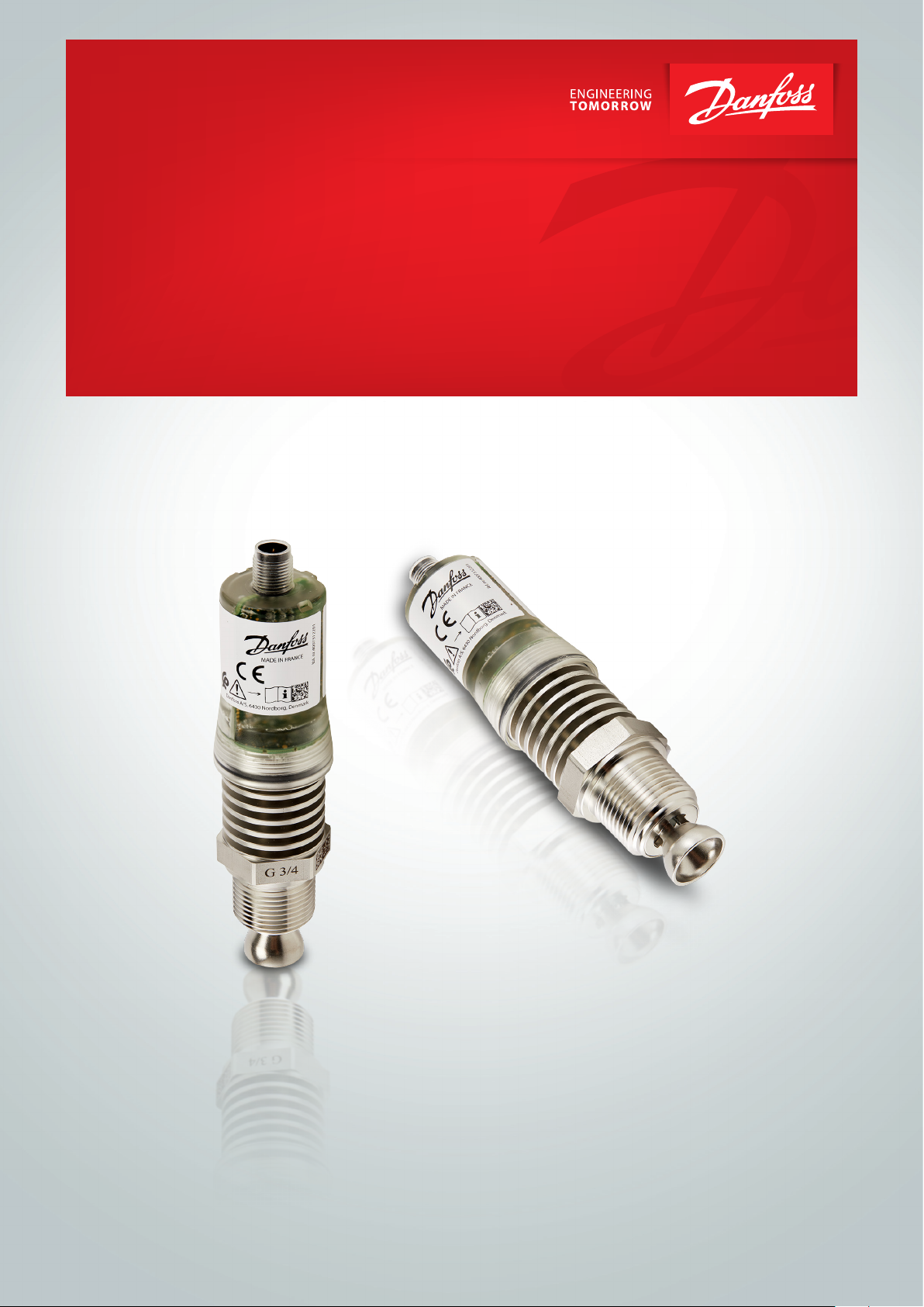
Safety Guide
LLS 4000/4000U

Safety Guide | LLS 4000/4000U
Contents Introduction .......................................................................................................................................................................................................................................................................................................................... 3
Scope of the document ............................................................................................................................................................................................................................................................................ 3
Revision history ........................................................................................................................................................................................................................................................................................................ 3
Device description .............................................................................................................................................................................................................................................................................................. 3
Device variants .......................................................................................................................................................................................................................................................................................................... 4
Related documentation............................................................................................................................................................................................................................................................................. 4
Terms and denitions ....................................................................................................................................................................................................................................................................................5
Specication of safety function ......................................................................................................................................................................................................................................................... 6
Preliminary requirements ........................................................................................................................................................................................................................................................................6
Denition of the safety function ................................................................................................................................................................................................................................................. 6
General notes .............................................................................................................................................................................................................................................................................................. 6
Definition of the safety function ...................................................................................................................................................................................................................................... 6
Process response time .....................................................................................................................................................................................................................................................................6
Safety function characteristics ........................................................................................................................................................................................................................................... 7
Safety application conditions (SAC) ...................................................................................................................................................................................................................................... 7
Operation ................................................................................................................................................................................................................................................................................................................................... 9
Conditions of use .................................................................................................................................................................................................................................................................................................. 9
Failure state .....................................................................................................................................................................................................................................................................................................................9
Switch output - relay ................................................................................................................................................................................................................................................................................... 9
Error conditions ....................................................................................................................................................................................................................................................................................................... 9
User parameters .........................................................................................................................................................................................................................................................................................................10
Limits for change of parameters .............................................................................................................................................................................................................................................10
Service .......................................................................................................................................................................................................................................................................................................................................... 11
Periodic maintenance ...............................................................................................................................................................................................................................................................................11
Availability of services ............................................................................................................................................................................................................................................................................... 11
Operation modes and proof tests ........................................................................................................................................................................................................................................11
Continuous and high demand mode .................................................................................................................................................................................................................. 11
Low demand mode ........................................................................................................................................................................................................................................................................11
Proof test ........................................................................................................................................................................................................................................................................................................11
Equipment needed .......................................................................................................................................................................................................................................................................... 12
How to make sure that the device installation is correct ...........................................................................................................................................................12
How to make sure of the relay output capability .................................................................................................................................................................................13
How to make sure of the correct behavior of the device ............................................................................................................................................................13
Troubleshooting .................................................................................................................................................................................................................................................................................................14
Technical Data ...............................................................................................................................................................................................................................................................................................................15
Characteristics for the device safety function ..................................................................................................................................................................................................15
Assumptions .............................................................................................................................................................................................................................................................................................................16
FMEDA is applicable for the conditions that follow: ........................................................................................................................................................................16
Support for SIL-approved devices ........................................................................................................................................................................................................................................16
Appendix ............................................................................................................................................................................................................................................................................. 17
Proof test report form (for copying) ..................................................................................................................................................................................................................................17
2 | BH331633043895en-000501
© Danfoss | Climate Solutions | 2022.03
Safety Guide | LLS 4000/4000U
Introduction Scope of the document
This document supplies functional safety data about the device. This data agrees with the IEC 61508
standard.
General hint
This level detector is a functionally-safe level detector. It may be deployed within safety critical
systems requiring the safety function (for more data, refer to Specication of the safety function on
page 7) at a safety integrity level 2.
In case of a detected potentially hazardous failure, the system performs a safety reaction to bring the
device to a safe state, which is indicated by a safe position on the output relay. Depending on the
failure class, the device will resume the detection mode as soon as the cause of the failure disappears
(application dependent failure) or remains in failure mode (internal system failure). In the latter case,
operator’s interaction is required to restart the detection mode.
For safe operation, the operator / integrator must full some conditions. These conditions are dened
as Safety Application Conditions (SAC). For more data, refer to Safety application conditions (SAC) on
page 7.
INFORMATION!
The data in this supplement only contains the data applicable to the SIL approval. The technical data
for the standard version in the Datasheet (document [N1]) shall be valid, provided that it is not
rendered invalid or replaced by this supplement. If necessary, parts of document [N1] are referenced herein.
INFORMATION!
Installation, commissioning and maintenance may only be carried out by approved personnel.
Device description
Detections are given through 1 output options:
• one switch output - relay
Detections can also be displayed via an application on a smart device with Bluetooth connection. The
switch output - relay is the safety function.
When the device detects a measurement error, it switches the output relay to “safe” position. The “safe”
position is the OPEN state.
Refer also to “Device description” in the Datasheet (document [N1]).
© Danfoss | Climate Solutions | 2022.03
BH331633043895en-000501 | 3
Safety Guide | LLS 4000/4000U
x
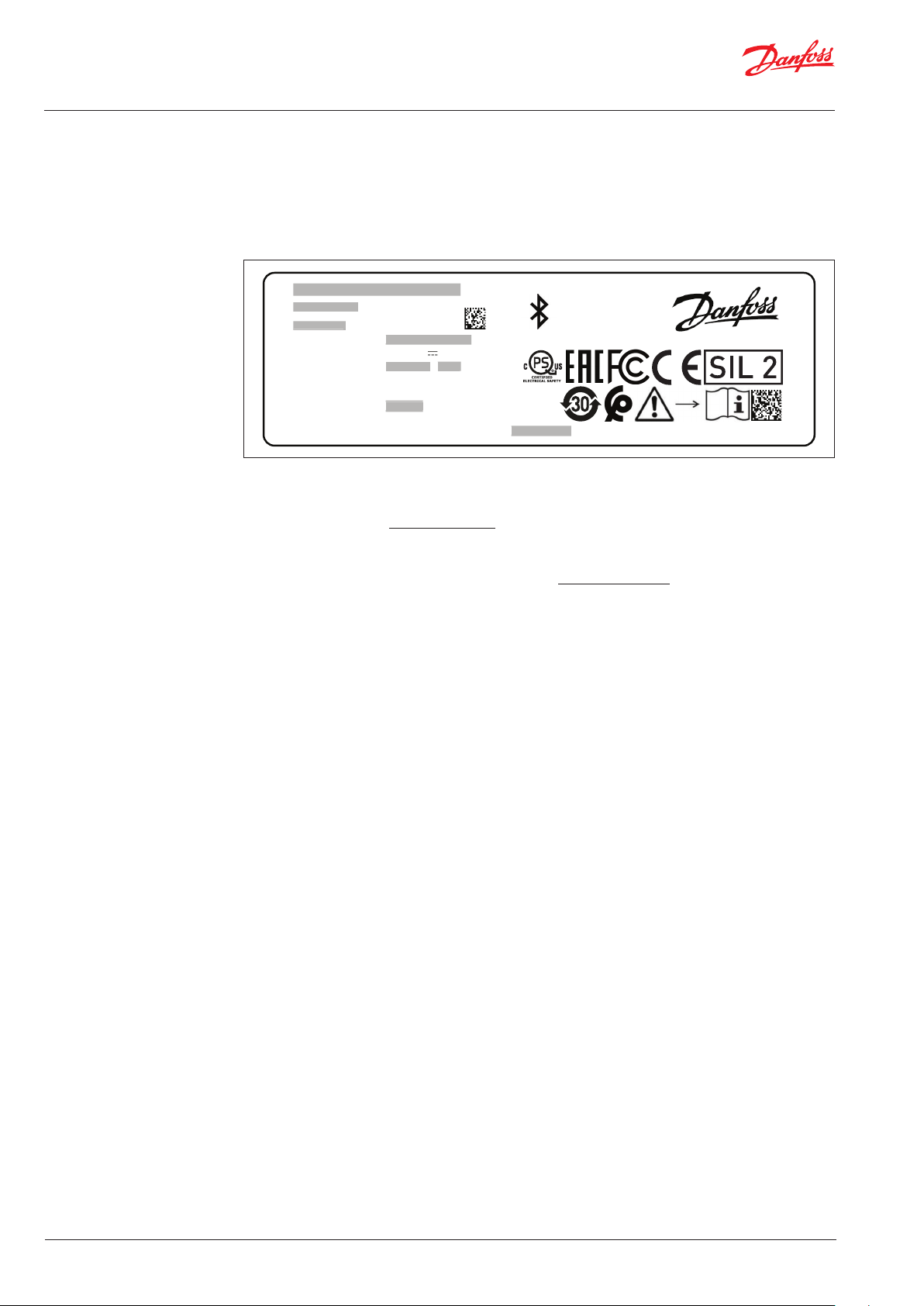
Device variants
The model name for the level transmitter and its options are identied by the VF type code on the
device nameplate.
The SIL variant of the device shows a SIL2 logo on the device nameplate. When this logo appears on
the device nameplate, the device is delivered for safety applications If this logo does not appear on
the device nameplate, the device shall not be used for safety applications.
xxxxxxxxxxxxxxxx
xxxxxxxxxxxxxxx
xxxxxxxxx
xxxxxxxx
xxxxxxx
S/N: xxxxxxxxxxxxxxxx
Supply: 24 V DC 80 mA
Connection type: xxxxxxxx / xxxx
MWP (PS): 65 bars
Process temp.: -50°C to +120°C
MD: xxxx/xx IP66/IP67
FCC ID:
IC: 1991D-SWSILBT01 CMIIT: xxxxxxxxxxx
xxxxxxxxxxxxxxxx
xxxxxxxx xxxx
xxxx/xx
Q6BSWSILBT01
xxx PV01
xxxxxxxxxxx
Danfoss A/S, 6430 Nordborg, Denmark
MADE IN FRANCE
lbl. nr. FZ 4007312201
Figure 1-1: Location of the SIL logo on the device nameplate is in the middle right
Related documentation
[N1] LLS 4000 Datasheet AI323832972563
[N2] IEC 61508-1 to 7: 2010 Functional safety of electrical / electronic / programmable electronic
safety-related systems
[N3] Liquid Level Switch Installation guide/Quick start AN317523977313
4 | BH331633043895en-000501
© Danfoss | Climate Solutions | 2022.03
Safety Guide | LLS 4000/4000U
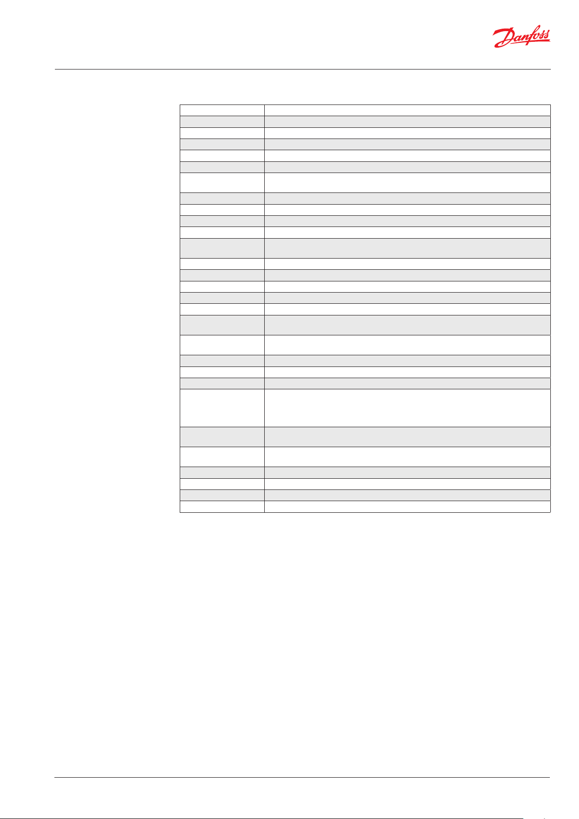
Terms and denitions
DC
D
Diagnostic Coverage of dangerous failures
Firmware Software embedded in the device
FIT Failure In Time (1×10⁻⁹ failures per hour)
FMEDA Failure Modes, Eects and Diagnostics Analysis
FRT Fault Response Time (diagnostic test interval + Fault Reaction Time)
HFT Hardware Fault Tolerance
High demand or
continuous mode
λ
DD
λ
DU
λ
SD
λ
SU
Low demand mode
Where the frequency of demands for operation made on a safety-related system is greater
than one time per year
Rate for dangerous detected failure
Rate for dangerous undetected failure
Rate for safe detected failure
Rate for safe undetected failure
Where the frequency of demands for operation made on a safety-related system is no
greater than one time per year
MTBF Mean Time Between Failures
MTTF Mean Time To Failure
MTTR Mean Time To Recovery
PFD
AVG
Average Probability of Failure on Demand
PFH Probability of a dangerous Failure per Hour
Process safety time
Safety Application
Conditions
The time interval between a potentially dangerous failure and an error value from the
current output
Conditions that are demands to be observed when using a safety related system or subsystem
SFF Safe Failure Fraction
SIL Safety Integrity Level
SIS Safety Instrumented System
Measure (expressed on a scale of SC 1 to SC 3) of the condence that the systematic safety
Systematic Capability
integrity of an element meets the requirements of the specied SIL, in respect of the
specied element safety function, when the element is applied in accordance with the
instructions
Type A system
Type B system
"Non-complex" system (all failure modes are well dened). For more data, refer to
subsection 7.4.3.1.2 of IEC 61508-2
"Complex" system (all failure modes are not well dened). For more data, refer to
subsection 7.4.3.1.2 of IEC 61508-2
T[Proof] Proof Test Interval
T[Repair] Time to Repair
T[Test] Internal Diagnostics Test Interval
2oo2 2 out of 2 channels architecture
© Danfoss | Climate Solutions | 2022.03
BH331633043895en-000501 | 5

Safety Guide | LLS 4000/4000U
Specication of
safety function
Preliminary requirements
The device must be operated within the process and ambient conditions specied in the Datasheet
(document [N1]) of the device.
The following chapter denes additional conditions, which have to be obeyed for safety applications
Denition of the safety function
General notes
The device contains a safety function that agrees with International Standard IEC 61508 (document [N2])
This safety function operates if the device detects a liquid in front of it.
Denition of the safety function
Within a maximum fault response time of 10s, the device sets its output relay to its fundamental state
(open) if the level of a specied liquid in a tank has reached the middle of the sensing interface ±5 mm
tolerance.
The safety integrity level of this safety function is SIL2.
Fault response time
The fault response time is the time that is necessary for the device to go into safe state after an error
occurred in the safety function.
The maximum time is 10 seconds, as it is the time for the device to run all its internal diagnostics.
.
6 | BH331633043895en-000501
© Danfoss | Climate Solutions | 2022.03

Safety Guide | LLS 4000/4000U
Safety function characteristics
The safety function uses only digital binary output signal to indicates the presence of the product and
give the device status.
WARNING!
The device must have the applicable options and settings for the application. The ambient and
process conditions must agree with the technical data given in the Datasheet (document [N1]) and
this document
(safety guide). You must obey the installation instructions given in the Datasheet
(document [N1]).
Function input None
Function output Switch output - relay
If the device nds a fault:
Output relay, safe
state
Open
(Remark: The relay is considered as Open even in case of the output oscillates between
close and open)
If a logic solver is used, it must use the output relay safe state to set itself to a fail-safe condition.
Safety application conditions (SAC)
Installation (refer to Installation guide - AN317523977313)
• The device must be installed with a minimum distance to any object (e.g. TDR probe) in front of the
sensing part. The minimum distance is 25 mm
• The device must be installed with a maximum angle relative to horizontal in order to avoid liquid
reservoirs. The maximum angle is 10°
• The device must be installed to avoid overow due to a potential thicker layer of foreign liquid on top
of the media in focus (like oil on refrigerant). Foreign liquid might not be detected and could
potentially provoke an overow
• The mechanical part of the device must not be disconnected from the electronic part of the device.
The change of the electronic part is not allowed as it would lead to a signicant loss of accuracy and
the device would not be able to sense the product correctly
Operation
• The device must not be used for products with a viscosity above 5000 cps
• The device must not be used with foreign particles in the medium. Foreign particles can cause the
device to detect the medium incorrectly
• The device must be tested after installation to ensure correct functionality. See chapter §5.3 for proof
tests denition
• The device won’t detect the presence of gas or the bubbles of a liquid medium. The device is
parametrized to detect only a liquid phase of a product
• When the device reset in case of error detection, the relay stays in a safe position for at least
100 milliseconds
© Danfoss | Climate Solutions | 2022.03
BH331633043895en-000501 | 7

Safety Guide | LLS 4000/4000U
Functionally-safe conguration
• The device must be congured accordingly with the real product in the tank. This setting is in the
parameter “Product Type”. By default, this parameter is set to Ammonia
• It is only possible to use the safety function with:
• The safe state relay is set to “OPEN”. The normally open relay setting is not able to guarantee the
safety function of the devices
• Device protects from product overll. The device is not able to protect safely enough the
emptiness state of a tank
• If you use the device in a continuous mode or high demand mode of operation, the process safety
time must be more than 10 seconds. This minimum time agrees with International Standard
IEC 61508 Part 2 (document [N2]), section 7.4.4.1.4
• If you use the device in a high demand mode of position, the maximum frequency of demands is
1 demand every 17 minutes. This frequency agrees with International Standard IEC 61508 Part 2
(document [N2]), section 7.4.4.1.4
Functionally-safe use of the Bluetooth communication
The communication with the device is authorized using the Bluetooth communication and the
dedicated application with the following restrictions.
• The default PIN code of a device is 0000. This code must be changed at start. To change this code
please check the installation guide (document [N3])
• The dedicated application permits to change the settings of the device. For safety reason, it is only
possible to change the parameter “Product Type” within the rst 15 minutes after the starting up of
the device
After the change of parameter(s), the device proceeds to a warm reset and restart with new
parameters. The relay set its state to a safe state for 2 seconds.
If a device is connected to logic solver, the logic solver should implement a diagnostic when
this case happens
• The dedicated application can be used with a specic mode to test the entire safety loop (proof tests).
For this test, the relay must be set OPEN or CLOSE.
This means that the safety information of the device is not guarantee during this part of proof test
• The Bluetooth communication is only used for set-up, calibration and diagnostic purposes. It is not
used during safety operation mode
WARNING!
The use of the latest revision available of the smartphone application is mandatory. If the
application doesn’t have the possibility to check if a new version exists, you have to check it by
yourself.
8 | BH331633043895en-000501
© Danfoss | Climate Solutions | 2022.03

Safety Guide | LLS 4000/4000U
Operation
Conditions of use
WARNING!
Only approved personnel can change device settings. Keep a report of changes to the device
settings. These reports must include the date, the menu item, the old parameter and the new
parameter.
The conguration is protected with a password. For more data on password protection and device
conguration, refer to the “Conguration” chapter in the installation guide (document [N3]).
Failure state
Switch output - relay
Output relay state Description
CLOSED
OPEN
Information of safe measurement, the device does not
detect product
The safety function changes the value to the “safe state”,
when the device detects a product, or the internal
diagnostics detect a safe or dangerous detected failure.
Error conditions
The device can sense the error conditions in the table that follows. When the device detects a
measurement error, it supplies the “safe” position on the output relay.
Error condition Cause
Device does not start immediately
Component hardware errors
Ambient temperature is too high The ambient temperature is more than 80 °C (176 °F)
Ambient temperature is too low The ambient temperature is less than -40 °C (-40 °F)
Incorrect detection signal The device is not able to sense correctly the product
This error occurs if more than 5 seconds are necessary to
start the device
Memory failure internal to the device
Voltage failure internal to the device
No signal for product detection
Microcontroller failure internal error
Antenna resonance is not correct
© Danfoss | Climate Solutions | 2022.03
BH331633043895en-000501 | 9

Safety Guide | LLS 4000/4000U
User parameters INFORMATION!
If you change a parameter in one or more of the menu items that follow, this will have an eect on the
safety function.
Limits for change of parameters
CAUTION !
If you change the values of one or more of the parameters given in the “User parameters” section, this can have
an unwanted eect on the safety function. Do a check of the safety function after you change a parameter.
LEGAL NOTICE!
The manufacturer declines all responsibility for the correct operation of the safety function if these
parameters are changed by the customer with the service access.
Parameter name Function description Selection list
Media Type
Switch State
Selection of the type of media
the device measure.
State of the relay when the
device does not detect the
presence of the media
List of possible medias* Ammonia
Normally Close,
Normally Open
Default value and
comments
Normally Close
It is not possible to change
this value for SIL devices
* See AI323832972563, LLS 4000 Data Sheet for complete list of medias.
CAUTION !
If the smartphone or the application crashed during parametrization, check the parameters of the
device before using the safety function.
10 | BH331633043895en-000501
© Danfoss | Climate Solutions | 2022.03

Safety Guide | LLS 4000/4000U
Service Periodic maintenance
You must follow the maintenance instructions given in the Datasheet (document [N1]).
Operation modes and proof tests
Continuous and high demand mode
If you operate the level transmitter in a continuous or high-demand mode in the specied
environmental limits, calculate the frequency to perform the necessary proof tests during its useful
lifetime (for more data, refer to Characteristics for the device safety functions on page 15). Obey safety
application conditions (SAC) that relate to useful lifetime and constant failure rates.
Low demand mode
The level transmitter includes a comprehensive set of online diagnostic tests which are executed
fast and frequently, resulting in a very low mean down time. Assuming reasonable low repair and
restoration times as well, the device fulls SIL2-compatible PFD values.
Proof tests
It is necessary to do proof tests to make sure that the safety function is applicable to the product
detection.
• The device settings must be correct. If a parameter is incorrect, the device will not detect correctly
• The electronic components must not be defective
• The software programs (rmware etc.) must operate correctly
• The mechanical installation of the device must not have an eect on the performance of the
sensing part
We recommend that you do a proof test:
• Immediately after you install and start the device
• Immediately after you change the parameters of the device
© Danfoss | Climate Solutions | 2022.03
BH331633043895en-000501 | 11

Safety Guide | LLS 4000/4000U
WARNING!
SIS engineers must calculate the interval of proof tests. This interval must agree with the specied
PFD
. The minimum time between proof tests must be less than 5 years, but the interval between
AVG
proof tests must also agree with the safety system used on site.
Prepare the device for the proof tests.
CAUTION !
• Proof tests done by the customer must be equivalent or more dicult than the tests given in this
section
• Keep a report of each proof test. These reports must include the date, the tests results (performance
of the safety function or faults found), a list of approved personnel who did the test and the report
revision number. These reports must be put into storage and made easily available. A proof test
report form (for copying) is available on page 18
• If the proof test results are not correct because the device is not set correctly or it does not detect
the product, speak or write to the manufacturer
• The location of the device and how it is installed on the tank can have an eect on the performance.
Make sure that you obey the installation instructions given in the installation guide (document [N3])
• Disconnect the device from the safety system PLC when you do proof tests because this system
conguration can open the circuit breaker
Equipment needed
• Device installed on the process
• Smartphone application connected to the device
• ohmmeter
• Reference device: an approved level meter or indicator
Reference device
4 3
1 2
Tank
Power
supply
How to make sure that the device installation is correct
Do a visual check of the device position
• Check that the device is set on the tank to prevent for overlling
Do a visual check of the device
• Check on the device nameplate if the following SIL logo appears
SIL 2
ohmmeter
12 | BH331633043895en-000501
© Danfoss | Climate Solutions | 2022.03

Safety Guide | LLS 4000/4000U
Do a check of the Product Type
• Power the device
• Power the smartphone and launch the application
• Connect the device with the smartphone application
• Go into section CONFIGURATION
• Check the Product Type parameter is correctly set according to the product in the tank
• If the Product Type parameter is not set correctly then the test is a failure
Do a check of the Relay State conguration
• Connect the device with the smartphone application
• Go into section CONFIGURATION
• Check the “Switch State” parameter is set to “Normally Closed”. If the parameter is not
“Normally Closed” then the test is a failure
How to make sure of the relay output capability
Do a check of the output relay “safe” position
• Power the device
• Power the smartphone and launch the application
• Connect the device with the smartphone application
• Go into “settings” and Login with service password
• Open the section “Relay switch test”
• Click on the button “OPEN RELAY”
• Check the output relay for more than 10 seconds:
• if the value of the ohmmeter is greater than 50 ohms during the 10 seconds, the output relay is
considered as open. This test is successful
• If the value of the ohmmeter is spuriously lower or equal than 50 ohms during the 10 seconds,
the output relay must be considered as close. This test is a failure
Click on “EXIT TEST” to end the checking of the open state of the relay.
WARNING: If there is no action on “EXIT TEST”, the relay will stay open independently of the product
detection.
Do a check of the output relay normal position
• Power the device
• Power the smartphone and launch the application
• Connect the device with the smartphone application
• In the settings, enter the device service login
• Go into section Additional info
• Click on the button “CLOSE RELAY”
• Check that the output relay is close: if the value of the ohmmeter is lower than 50 ohms, the relay of
the device is close. This test is successful
Click on “EXIT TEST” to end the checking of the close state of the relay.
WARNING: If there is no action on “EXIT TEST”, the relay will stay close independently of the product
detection, and can hide a dangerous state.
How to make sure of the correct behavior of the device
Do a functional check of the device
• Power the device
• Use the reference level indicator for setting the level below the device position
• Check the output relay is close: if the value of the ohmmeter is lower than 50 ohms, the relay of
the device is close
• Use the reference level indicator for lling the tank until the level gets higher than the device
position
• Check the output relay is open: if the value of the ohmmeter is greater than 50 ohms, the relay
of the device is open
• Use the reference level indicator for emptying the tank until the level gets lower than the device
position
• Check the output relay is close: if the value of the ohmmeter is lower than 50 ohms, the relay of
the device is close
• If the relay of the device is not set properly in the previous checks, then the test is a failure
© Danfoss | Climate Solutions | 2022.03
BH331633043895en-000501 | 13

Safety Guide | LLS 4000/4000U
CAUTION !
Do a visual inspection of the housing, seals and electrical wires to make sure that they are serviceable.
If you do the tests in this section, it is possible to get this proof test coverage:
Device information Proof test coverage (PTC)
Output relay 95%
Troubleshooting
INFORMATION!
Modications to the device are not permitted.
Only approved personnel can repair the device.
If you nd a problem, please contact your local representative. If the device must go back to the
manufacturer.
Send a report to the manufacturer if there is a failure that is related to functional safety. If you nd a
problem, please contact your local representative.
14 | BH331633043895en-000501
© Danfoss | Climate Solutions | 2022.03

Safety Guide | LLS 4000/4000U
Technical Data
Characteristics for the device safety function
Version LLS 4000
Product Version PV02
Device type Type B system
Systematic capability 2
Safety integrity level
Dual channel SIL2
Architecture 2oo2
HFT 1
PFH 7.37 x 10
SFF 98%
λ
SD
λ
SU
λ
DD
λ
DU
PFD
(T[Proof ] = 1 year) 2.48 x 10
AVG
PFD
(T[Proof ] = 3 years) 7.43 x 10
AVG
PFD
(T[Proof ] = 5 years) 1.24 x 10
AVG
Proof test coverage 95%
Diagnostic test interval 10 s
Fault reaction time < 1 s
MTBF 304 years
5.1 x 10
160 x 10
165 x 10
5.65 x 10
-9
-9
-9
-9
-9
-5
-5
-4
© Danfoss | Climate Solutions | 2022.03
BH331633043895en-000501 | 15

Safety Guide | LLS 4000/4000U
Assumptions
FMEDA is applicable for the conditions that follow:
• Use of the device agrees with its design and performance characteristics. This includes ambient and
process conditions
• Installation of the device must agree with the instructions and the requirements of the application
• We can ignore wear of mechanical parts. Failure rates are constant
• Failures that follow one after the other are put in the same group as the failure that is the source of
the problem
• The Bluetooth protocol is only used for set-up, calibration and diagnostic purposes. It is not used
during safety operation mode
• All components that are not part of the safety function and cannot inuence the safety function
(feedback immune) are not included
• The output relay is used for safety applications
• The Mean Time to Recovery after safe failure is 72 hours (MTTR = 72 h)
• External power failure rates are not included
INFORMATION!
The FMEDA of the device was calculated with the exida tool FMEDA v7.1.17, with the conguration that
follows:
Database SN 29500
Ambient temperature is 40 °C
T[Proof] is from 1 to 10 years (87600 hours)
T[Repair] is 72 hours
T[Test] is 10 seconds (all internal test functions are done a minimum of one time during this period)
Support for SIL-approved devices
If the manufacturer makes a modication that has an eect on the safety function of the device, the
manufacturer will tell you about the modication immediately.
16 | BH331633043895en-000501
© Danfoss | Climate Solutions | 2022.03

Safety Guide | LLS 4000/4000U
Appendix Proof test report form (for copying)
CAUTION !
Complete the report form that follows when you do a proof test.
For more data, refer to Proof tests on page 11.
Recorded by: Date:
Unique device ID (e.g. serial number):
Recorded value Correct value Approved
Device mounting position Device protects overlling. [Yes] [No]
Visual check of the SIL logo
Product Type parameter value Value according to the product in the tank [Yes] [No]
Relay Init State parameter value Value set to 0 (zero) [Yes] [No]
Recorded value Correct value Approved
Check output relay in “safe”
position
Check output relay in normal
position
With a level below the device
position, output relay is in
normal position
With a level increasing above
the device position, output
relay is in “safe” position
With a level decreasing below
the device position, output
relay is in normal position
Parameter value check
Proof tests results
There is the logo
Functional check
Proof tests results
output relay is open (ohmmeter gives an
error or >50 ohms)
output relay is closed (ohmmeter gives an
error or <50 ohms)
output relay is closed (ohmmeter gives an
error or <50 ohms)
output relay is open (ohmmeter gives an
error or >50 ohms)
output relay is closed (ohmmeter gives an
error or <50 ohms)
on the nameplate
SIL 2
[Yes] [No]
[Yes] [No]
[Yes] [No]
[Yes] [No]
[Yes] [No]
[Yes] [No]
Conclusion
Does the device operate satisfactorily in safety-related systems? [Yes] [No]
Signature:
© Danfoss | Climate Solutions | 2022.03
BH331633043895en-000501 | 17

18 | BH331633043895en-000501
© Danfoss | Climate Solutions | 2022.03
 Loading...