

Page 1

MAKING MODERN LIVING POSSIBLE
living connect®
Installation and User Guide
Danfoss Heating Solutions
Page 2

2
living connect®
Page 3

Thank you f or buying a Danfoss product
Danke für d en Kauf eines Dan foss Produkts
Tak fordi du købte et Danfoss produkt
Bedankt dat u een Danfoss product heeft g ekocht
UK
DE
DK
NL
Danfoss Heating Solutions
3
Page 4
Contents
UK
1. System overview ................................................................ 5
DE
2. Overview of display and control buttons ................. 5
3. Installation - step by step ................................................6
DK
3.1 Preparation ................................................................ 6
NL
3.2 Installation of living connect® .............................6
3.3 Configuring Danfoss LinkTM CC ..........................7
3.4 Connecting to Danfoss LinkTM CC ...................... 9
4. Technical settings..............................................................10
4.1 Reinstallation mode ............................................. 10
4.2 Testing the connection .......................................10
4.3 Adjustments for over/undersized radiators 11
4.4 Reset to factory settings ....................................11
4.5 Technical data ........................................................12
5. Safety precautions ............................................................ 13
6. Removing living connect® ..............................................13
7. Disposal ................................................................................13
User Guide ...............................................................................14
4
living connect®
Page 5
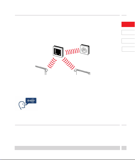
1. System overview
living connect® is an electronic radiator thermostat
for homes. It is controlled by a central device called a
Danfoss LinkTM CC.
Danfoss LinkTM CC can also control floor heating and
on/off switches in the building.
Danfoss LinkTM CC
living connect®
Danfoss LinkTM RS
UK
DE
DK
NL
Please refer to the separate Danfoss LinkTM CC and
room sensor Danfoss Link
information.
technology. More information is
available at www.danfoss.com/living
living connect® uses Z-Wave wireless
TM
RS manuals for more
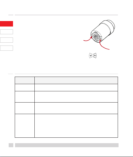
2. Overview of display and control buttons
See page 15.
Danfoss Heating Solutions
5
Page 6
3. Installation - step by step
3.1 Preparation
UK
living connect® is supplied with adapters for Danfoss
RA valves and valves with M30X1.5 (K) connections
DE
(014G0002), two alkaline AA batteries and a 2 mm
Allen key.
DK
Inserting the batteries
NL
Remove the battery cover and insert
the two batteries.
Ensure that the batteries are correctly
inserted. M must flash on the display before
installation, if this is not the case, see reinstallation
mode page 10.
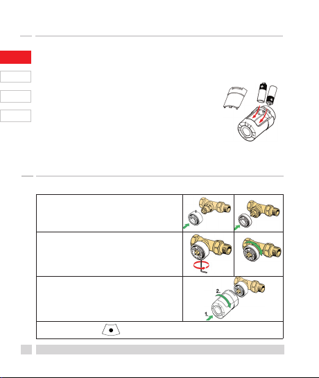
3.2 Installation of living connect®
1. Start by mounting the the adapter.
2. Tighten the RA adapter using the
Allen key.
Tighten the K adapter by hand
(max. 5 Nm).
3. Screw the thermostat onto the
adapter and hand-tighten (max.
5 Nm).
4. Press and hold for approx. 3 seconds to fix the thermostat.
6
RA K
2mm
Key
living connect®
Page 7
3. Installation - step by step
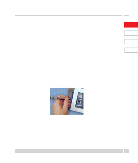
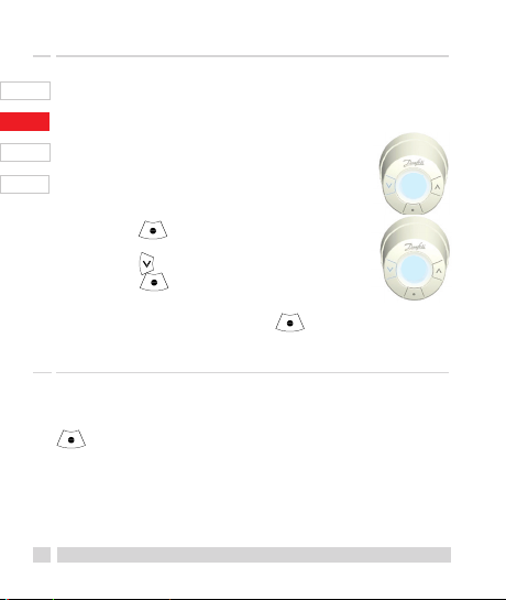
3.3 Configuring Danfoss LinkTM CC
For practical reasons, it is recommended that the
Danfoss LinkTM CC is connected to a battery pack
(014G0262). This makes the device mobile, and it can
then easily be positioned at a distance of up to 1.5 m
from each radiator thermostat that is to be added to
the system.
Remove the front cover from the Danfoss LinkTM CC
by carefully levering it off, starting with the bottom
corners. Press and hold down the setup button using
a ballpoint pen for approximately three seconds to
start the installation menu (the start-up phase may
take several minutes).
For Help, press ? in the lower right corner.
For installation without a battery pack, please see
www.danfoss.com/living.
Danfoss Heating Solutions
UK
DE
DK
NL
7
Page 8
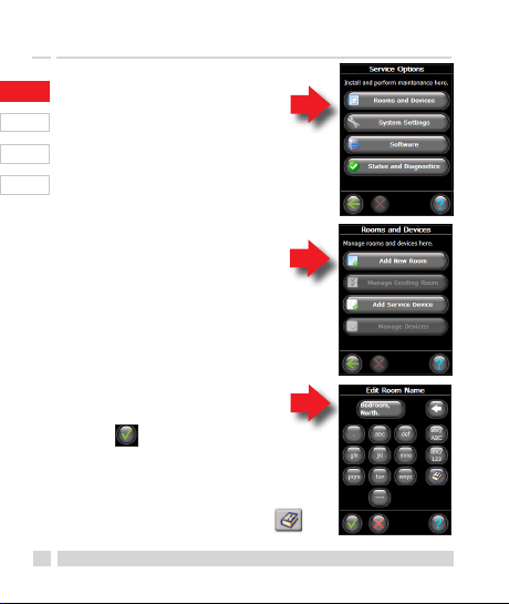
3. Installation - step by step
1. Configure the rooms
UK
in which the radiator
thermostats have been
DE
installed.
DK
NL
2. Add a new room.
3. Edit or enter the
room name.
Press to confirm.
Note – a list of common room names
can be found using this button
8
living connect®
Page 9
3. Installation - step by step
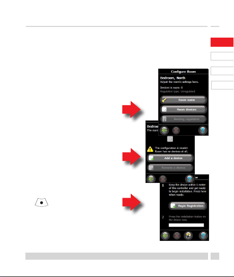
3.4 Connecting to Danfoss LinkTM CC
Each thermostat must be connected to the Danfoss
LinkTM CC. This is best done by standing beside each
thermostat with the Danfoss LinkTM CC (connected to
the recommended 014G0262 battery
pack).
1. The “Configure room”
menu is displayed.
Select “Room devices”.
2. Select “Add a device”.
3. Press Begin Registration,
and then press and release
on the thermostat.
4. Repeat for each device.
5. Once all devices have been
registered and the Danfoss LinkTM CC
is placed in its final position, perform
a network test (see separate Danfoss
LinkTM CC manual).
Danfoss Heating Solutions
UK
DE
DK
NL
9
Page 10
4. Technical settings
4.1 Reinstallation mode
If the thermostat has been removed from the radiator
UK
and needs to be reinstalled (after being used), it is
DE
necessary to activate installation mode to prevent
damage to the thermostat.
DK
To enter installation mode:
NL
Press until M is displayed.
Press to withdraw the spindle.
M flashes.
Reinstall the thermostat on the valve.
Press for approx. 3 seconds to exit.
Please also refer to section 6 regarding removal of the thermostat from the
radiator valve.
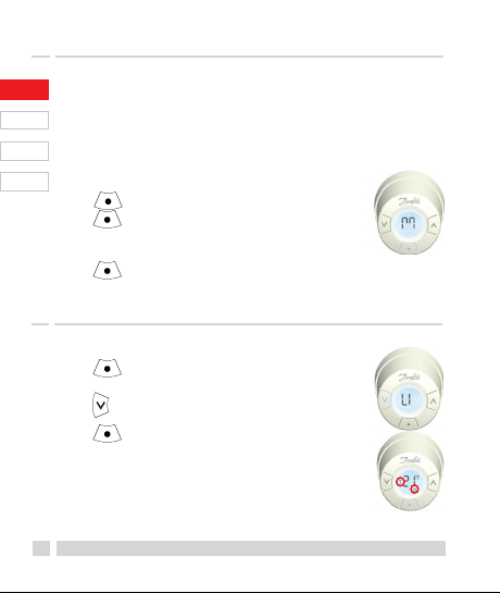
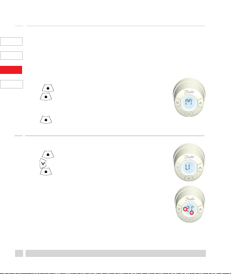
4.2 Testing the connection
Press for at least 3 seconds until M is
displayed.
Press until LI is displayed.
Press to make the connection.
LI disappears when the connection is made.
If no connection can be made, the alarm
and antenna symbols flash together.
Refer to “Troubleshooting” at
www.danfoss.com/living
10
living connect®
Page 11
4. Technical settings
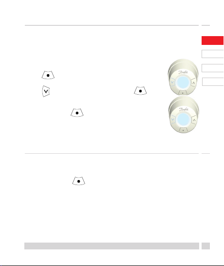
4.3 Adjustments for over/undersized radiators
The factory setting is P2.
Use P1 if the radiator appears oversized for the room.
Use P3 if it is undersized.*
Press for at least 3 seconds until
M is displayed.
Press until Pb is displayed. Press
Select P1, P2 or P3 using the arrow keys,
and exit using
*The frequency of P1, P2 and P3 regulation
varies to compensate for radiator over/under
sizing.
4.4 Reset to factory settings
Remove the battery cover and take out one battery.
Press and hold for approx. 5 seconds, while
reinserting the battery.
Danfoss LinkTM CC will then display “device removed”.
Press OK.
Note that if the thermostat is moved to another room, it
is recommended it be reset to the factory default settings.
The thermostat will be reset and disconnected from
Danfoss LinkTM CC.
Danfoss Heating Solutions
pb
p2
UK
DE
DK
NL
11
Page 12
4. Technical settings
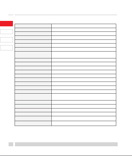
4.5 Technical data
UK
Actuator type Elec tromechanical
Software classification A
DE
Safety classification Type 1
Recommended use Residential
DK
Open window function Yes
Synchronizing Every 5 minute
NL
Mechanical strength 70 N (max. force from valve)
Maximum water tem-
perature
Movement type Linear
Battery life 2 years
Spindle movement 2-3 mm on the valve
Maximum extension 4.5 mm
Temperature sampling Measures temp. every minute
Speed of adjustment 1 mm/s
Power supply 2x1.5V AA alkaline, class III (SELV)
Power consumption 3 mW in standby, 1.2W when active
Ambient temperature 0° to 40°C
Transportation
temperature range
Temperature setting range 4 to 28°C
Size (mm) L: 91 Ø: 51 (RA)
Ball pressure test 75°C
Weight 177 g
Transmission frequency Wireless Z-Wave/868.42 MHz
IP class* 20
*This thermostat should not be used in hazardous
installations or in places where it will be exposed to
water.
12
90°C
-20 to 65°C
living connect®
Page 13
5. Safety precautions
The thermostat is not intended for children and must
not be used as a toy.
Please dispose of packaging materials in accordance
with local regulations and ensure all packaging is
kept away from children to prevent the possibility
of injury.
Do not attempt to dismantle the thermostat as it
contains no user-serviceable parts. Please return any
defective thermostat to the distributor.
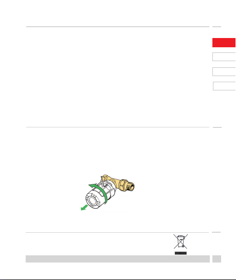
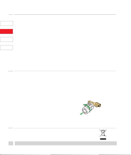
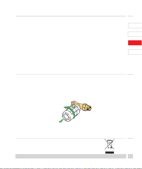
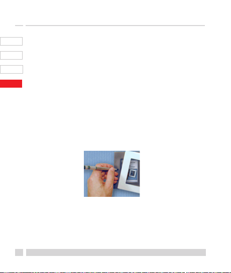
6. Removing living connect®
To remove the thermostat, insert an appropriate
tool in the hole in the thermostat's battery chamber
and in the hole in the black ring behind the chamber
(see illustration). Keeping the tool in position, turn
the entire thermostat anticlockwise until it is completely unscrewed.
See section 4.1 regarding reinstallation mode.
7. Disposal
The thermostat must be disposed of as
electronic waste.
Danfoss Heating Solutions
UK
DE
DK
NL
13
Page 14
User Guide for living connect®
UK
Contents
1. System overview ...............................................................14
DE
2. Overview of display and control buttons ................15
DK
3. Changing the batteries ...................................................15
NL
4. Temperature control and adjustment ....................... 16
5. Troubleshooting ................................................................16
1. System overview
See page 5.
14
living connect®
Page 15
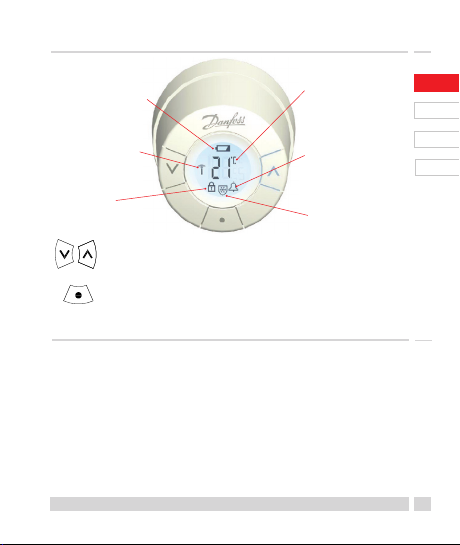
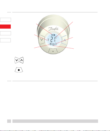
2. Overview of display and control buttons
Battery symbol Temperature
set point
Network
connection Alarm
Lock Frost
protection
Use these buttons to navigate within the
menu and to adjust the temperature.
Use this button to select the menu and
confirm choices.
3. Changing the batteries
When the battery level is low, the alarm bell and
battery icon will flash simultaneously.
If the battery goes flat, the system switches
automatically to frost protection mode.
Rechargeable batteries may not be used.
Note - please only use 1.5V AA alkaline batteries.
Remove the battery cover and insert two batteries.
Ensure that the batteries are correctly oriented.
Danfoss Heating Solutions
UK
DE
DK
NL
15
Page 16
4. Temperature control and adjustment
The temperature is usually
UK
controlled via Danfoss LinkTM CC,
but may be changed at any time
DE
using the thermostat's buttons. If
this is done, the thermostat sends
DK
a message to Danfoss LinkTM CC,
instructing it to synchronise the
NL
other thermostats in the room.
The change only remains in effect
until the next programmed period.
Temperature range 4-28°C
18
19
20
21
Press to change the
temperature.
5. Troubleshooting
Error code Error
E1 Transmitter failure. Contact your local service technician.
E2 Malfunction in thermostat's front temperature sensor.
E3 Malfunction in thermostat's rear temperature sensor.
Antenna
and alarm
bell symbol flash
together
Contact your local service technician.
Contact your local service technician.
No connection to Danfoss LinkTM CC, follow the
instructions at www.danfoss.com/living.
26
25
24
23
16
living connect®
Page 17
Inhalt
1. Systemüberblick ................................................................ 18
2. Überblick - Anzeige und Tasten ...................................18
3. Installation - Schritt für Schritt .....................................19
3.1 Vorbereitung............................................................ 19
3.2 living connect® installieren .................................. 19
3.3 Danfoss LinkTM CC konfigurieren ...................... 20
3.4 Mit Danfoss LinkTM CC verbinden .....................22
4. Einstellungen......................................................................23
4.1 Re-Installation/Installation nach Demon-
tage ............................................................................ 23
4.2 Die Verbindung prüfen ....................................... 23
4.3 Anpassung an Heizkörper und Raum ...........24
4.4 Auf Werkseinstellungen zurücksetzen ..........24
4.5 Technische Daten .................................................25
5. Sicherheitsvorkehrungen ..............................................26
6. Demontage living connect® .......................................... 26
7. Entsorgung .......................................................................... 26
Bedienungsanleitung ..........................................................27
UK
DE
DK
NL
Danfoss Heating Solutions
17
Page 18

1. Systemüberblick
living connect® ist ein elektronischer Heizkörperther-
UK
mostat zur Raumtemperaturregelung. Die Steuerung
erfolgt über das Zentralgerät „Danfoss LinkTM CC“.
DE
Dieses kann auch für elektrische oder WarmwasserFußbodenheizungen sowie Ein-Ausschalt-Relais
DK
eingesetzt werden.
NL
Danfoss LinkTM CC
living connect®
Weitere Informationen finden Sie in den jeweiligen
Bedienungsanleitungen für Danfoss LinkTM CC und
eventuell angeschlossener Komponenten wie Fußbodenheizungsregler oder Raumtemperaturfühler
Danfoss Link
TM
RS.
living connect® nutzt die Drahtlos-
Technologie Z-Wave. Weitere Informationen
siehe www.danfoss.com/living.
Danfoss LinkTM RS
2. Überblick - Anzeige und Tasten
Siehe Seite 28.
18
living connect®
Page 19

3. Installation - Schritt für Schritt
3.1 Vorbereitung
living connect® wird mit Adaptern für Danfoss RA-
Ventile und Ventile mit M30X1,5 Anschluss (K), zwei
Alkaline AA-Batterien sowie einem 2 mm Inbusschlüssel geliefert.
Batterien einlegen
Die Batterieabdeckung abnehmen und
die beiden Batterien einlegen.
Sicherstellen, dass die Batterien korrekt
eingelegt werden. M blinkt nun in der
Anzeige. Ist dies nicht der Fall, siehe Kapitel 4.1.
„Re-Installation/Installation nach Demontage“ auf der
Seite 23.
3.2 living connect® installieren
1. Mit der Montage des Adapters
beginnen.
2. Einen RA-Adapter mithilfe des
Inbusschlüssels festziehen.
Einen K-Adapter von Hand
(max. 5 Nm) festziehen.
3. Den Thermostat auf den Adapter
schrauben und handfest
(max. 5 Nm) anziehen.
4. ca. 3 Sekunden lang gedrückt halten, um den Thermostat
zu fixieren.
Danfoss Heating Solutions
RA K
2 mm
Schlüssel
UK
DE
DK
NL
19
Page 20

3. Installation - Schritt für Schritt
3.3 Danfoss LinkTM CC konfigurieren
UK
Aus praktischen Gründen empfiehlt sich der Anschluss
DE
des Danfoss LinkTM CC an das als Zubehör erhältiche
Batterieteil (014G0252). Damit ist das Gerät für die
DK
Erstinbetriebnahme und Anmeldung anzuschließender Komponenten, die in einem Abstand von 1,5 m vor-
NL
genommen werden, mobil einsetzbar. Sofern Ihnen
dieses Batterieteil nicht zur Verfügung steht, müssten
Sie das Gerät während der gesamten Programmierung dauerhaft mit Spannung versorgen.
Die Frontabdeckung des Danfoss LinkTM CC vorsichtig,
beginnend mit den unteren Ecken, abhebeln. Mit einem Kugelschreiber die Setuptaste ca. drei Sekunden
lang gedrückt halten, um das Installationsmenü zu
starten (die Initialisierungsphase kann einige Minuten
dauern).
Für Hilfe auf das ? in der unteren rechten Ecke drücken.
Informationen zur Installation erhalten Sie auch unter
www.danfoss.com/living.
20
living connect®
Page 21

3. Installation - Schritt für Schritt
1. Die Räume, in denen die
Heizkörperthermostate
eingebaut wurden,
konfigurieren.
2. Einen neuen Raum
hinzufügen.
3. Den Namen des Raumes
bearbeiten oder eingeben.
Zum Bestätigen drücken.
Hinweis – eine Liste mit gebräuchlichen
Raumnamen finden Sie mithilfe dieser
Schaltfläche
UK
DE
DK
NL
Danfoss Heating Solutions
21
Page 22

3. Installation - Schritt für Schritt
3.4 Mit Danfoss LinkTM CC verbinden
UK
Jede Komponente muss mit dem Danfoss LinkTM CC
verbunden sein. Das geht am besten, wenn man mit dem
DE
empfohlenen, mit Danfoss LinkTM CC verbundenen
Batterieteil (014G0262), neben der anzuschließenden
DK
Komponente steht (Abstand max. 1,5 m).
NL
1. Das Menü „Raum konfigurieren“ wird angezeigt.
Wählen Sie „Raumgeräte“.
2. Wählen Sie „Gerät hinzufügen“.
3. Drücken Sie auf Registrierung
beginnen, dann auf am
Thermostat.
4. Wiederholen Sie den
Vorgang für jedes Gerät.
5. Führen Sie einen Netzwerktest
durch, nachdem alle Geräte
registriert und der Danfoss LinkTM in
seine endgültige Position gebracht
wurden (siehe separates Danfoss
LinkTM CC Handbuch).
22
living connect®
Page 23

4. Einstellungen
4.1 Re-Installation/Installation nach Demontage
Wenn ein Thermostat nach einer Demontage wieder
montiert werden soll, muss immer der Installationsmodus aktiviert werden, um eine Beschädigung des
Thermostates zu vermeiden.
Zum Aktivieren des Installationsmodus:
Drücken Sie bis M angezeigt wird.
Drücken Sie , um die Spindel
zurückzubewegen.
M blinkt nun.
Installieren Sie den Thermostat auf das Ventilgehäuse.
Drücken Sie ca. 3 Sekunden lang, um die Montage
zu beenden.
Informationen zur Demontage finden Sie in Abschnitt 6.
4.2 Die Verbindung prüfen
Drücken Sie mindestens 3 Sekunden
lang, bis M angezeigt wird.
Drücken Sie , bis LI angezeigt wird.
Drücken Sie , um die Verbindung herzustellen.
Sobald die Verbindung hergestellt ist, wird LI
ausgeblendet.
Wenn keine Verbindung hergestellt werden
kann, blinken die Symbole Alarm und Antenne
gleichzeitig. Weitere Informationen unter „Fehlerbeseitigung“ unter www.danfoss.com/living
Danfoss Heating Solutions
UK
DE
DK
NL
23
Page 24
4. Einstellungen
4.3 Anpassung an Heizkörper und Raum
Jeder Raum hat eine gewisse Wärmeträgheit.
UK
Um eine eventuell vorhandene Unter- oder
DE
Überdimensionierung der Heizkörper und der Heizkörperleistung auszugleichen, kann eine Kompen-
DK
sation über das Gerät erforderlich werden.
Bei Überdimensionierung wird die Werks-
NL
einstellung P2 auf P3 verändert, bei Unterdimensionierung auf P1*.
Drücken Sie mindestens 3 Sekunden,
bis M angezeigt wird.
Drücken Sie , bis Pb angezeigt wird.
Drücken Sie
Wählen Sie P1, P2 oder P3 mithilfe der
Pfeiltasten und beenden Sie mit
*Die Regulierungshäufigkeit für P1, P2 und P3 variiert, um die Über-
bzw. Unterdimensionierung des Heizkörpers zu kompensieren.
4.4 Auf Werkseinstellungen zurücksetzen
Die Batterieabdeckung abnehmen und eine Batterie
entnehmen. Warten, bis das Display erlischt, dann
gedrückt halten, Batterie einsetzen und loslassen,
sobald das Display vollständig zu sehen ist.
Danfoss LinkTM CC zeigt nun „Gerät entfernt“ an.
Drücken Sie OK.
Beachten Sie: Es wird empfohlen, den Thermostat auf die Werkseinstellungen
zurückzusetzen, wenn er in einem anderen Raum montiert wird. Der Thermostat wird zurückgesetzt und vom Danfoss LinkTM CC getrennt.
24
living connect®
pb
p2
Page 25

4. Einstellungen
4.5 Technische Daten
Typ Elektromechanisch
Softwareklasse A
Sicherheitsklasse Typ 1
Empfohlener Einsatzzweck Wohnungen
Fensteröffnungserkennung Ja
Synchronisierung Alle 5 Minuten
Mechanische
Belastbarkeit
Maximale
Wassertemperatur
Bewegungsart Linear
Batterielebensdauer 2 Jahre
Spindelbewegung 2-3 mm am Ventil
Maximale Verlängerung 4,5 mm
Frequenz Temperaturmessung jede Minute
Anpassungsgeschwindigkeit 1 mm/s
Spannungsversorgung 2 x 1,5 V AA Alkaline, Klasse III (SELV)
Leistungsaufnahme Standby 3 mW, Aktiv 1,2 W
Umgebungstemperatur 0° bis 40°C
Temperaturbereich
Transport
Regelbereich 4 bis 28°C
Abmessungen (mm) Länge: 91 Ø: 51 (RA)
Kugeldruckprüfung 75°C
Gewicht 177 g
Übertragungsfrequenz Drahtlose Z-Wave Kommunikation/868,42 MHz
Schutzklasse* IP20
*Der Thermostat ist nicht geeignet für den Einsatz in
Gefahrenumgebungen oder in Umgebungen, in denen
er Wasser ausgesetzt ist.
Danfoss Heating Solutions
70 N (max. Druck vom Ventil)
90°C
-20 bis 65°C
UK
DE
DK
NL
25
Page 26
5. Sicherheitsvorkehrungen
Der Thermostat ist nicht für Kinder geeignet und
UK
darf nicht als Spielzeug verwendet werden.
Bitte entsorgen Sie Verpackungsmaterialien
DE
entsprechend den lokalen Bestimmungen und
stellen Sie sicher, dass alle Verpackungen für
DK
Kinder unzugänglich aufbewahrt werden, um die
Möglichkeit von Verletzungen auszuschließen.
NL
Den Thermostat nicht auseinanderen bauen, er
enthält keine vom Benutzer zu wartenden Teile.
Informieren Sie im Bedarfsfall Ihren Installateur.
6. Demontage living connect®
Zum Demontieren des Thermostats ein geeignetes
Werkzeug, z.B. Inbusschlüssel, in die Bohrung im
Batteriefach und in eine in dem dahinterliegenden
schwarzen Ring stecken. Mit dem in der Position
verbleibenden Werkzeug den gesamten Thermostat
gegen den Uhrzeigersinn drehen, bis er komplett
abgeschraubt ist.
Vor der Demontage muss sich
der Thermostat im Installationsmodus befinden.
Informationen zum Installationsmodus in Abschnitt 4.1.
7. Entsorgung
Der Thermostat muss als Elektronikschrott
entsorgt werden.
26
living connect®
Page 27
Bedienungsanleitung für living connect®
Inhalt
1. Systemüberblick ................................................................ 27
2. Überblick - Anzeige und Tasten ...................................28
3. Batterien wechseln ........................................................... 28
4. Temperatursteuerung und -anpassung .................... 29
5. Fehlerbeseitigung ............................................................29
1. Systemüberblick
Siehe Seite 18.
Danfoss Heating Solutions
UK
DE
DK
NL
27
Page 28
2. Überblick - Anzeige und Tasten
UK
Batterie-Symbol Temperatur einstellwert
DE
Netzwerk-
DK
verbindung Alarm
NL
Verriegelung Frost-
schutz
Tasten zur Navigation im Menü und zum
Anpassen der Temperatur.
Taste zur Menüauswahl und
zur Bestätigung der Auswahl.
3. Batterien wechseln
Wenn die Batterien fast leer sind, blinken die Symbole
für Alarm und Batterie gleichzeitig.
Wenn die Batterien komplett leer sind, schaltet das
System automatisch auf den Frostschutzmodus.
Wiederaufladbare Batterien dürfen nicht verwendet
werden.
Hinweis. Bitte nur 1,5 V AA Alkaline Batterien verwenden.
Die Batterieabdeckung abnehmen und zwei Batterien
einlegen.
Sicherstellen, dass diese korrekt eingelegt werden.
28
living connect®
Page 29

4. Temperatursteuerung und -anpassung
Die Temperatur wird normalerweise via Danfoss LinkTM CC gesteuert,
kann aber jederzeit mithilfe der
Tasten am Thermostat geändert
werden. Wenn dies geschehen
ist, sendet der Thermostat eine
Meldung an Danfoss LinkTM CC,
der dann eventuell in diesem Raum
vorhandene weitere Thermostate
synchronisiert. Die Änderung
bleibt lediglich bis zur nächsten
programmierten Periode wirksam.
18
19
20
21
Drücken Sie zum
Ändern der Temperatur.
5. Fehlerbeseitigung
Fehlercode Fehler
E1 Ausfall Transmitter. Benachrichtigen Sie Ihren Installateur
E2 Fehlfunktion Temperatursensor. Benachrichtigen Sie
E3 Fehlfunktion Temperatursensor. Benachrichtigen Sie
Symbole
Alarm und
Antenne
blinken
gleichzeitig.
(mit Angabe des Fehlercodes E1).
Ihren Installateur (mit Angabe des Fehlercodes E2).
Ihren Installateur (mit Angabe des Fehlercodes E3).
Keine Verbindung zu Danfoss LinkTM CC. Folgen Sie den
Anweisungen auf www.danfoss.com/living.
UK
DE
26
DK
25
24
NL
23
Danfoss Heating Solutions
29
Page 30

Indeks
UK
1. Systemoversigt............................................... ................ 31
DE
2. Oversigt over display og knapper .............................. 31
3. Installation - trin for trin ................................................. 32
DK
3.1 Indledende trin....................................................32
NL
3.2 Montering af living connect® ............................. 32
3.3 Konfiguration af Danfoss LinkTM CC ................33
3.4 Tilmelding til Danfoss LinkTM CC.......................35
4. Tekniske indstillinger ...................................................... 36
4.1 Genmontering ....................................................... 36
4.2 Test af forbindelse ...............................................36
4.3 Tilpasning til radiator og rum .........................37
4.4 Reset til fabriksindstilling ................................. 37
4.5 Tekniske data .........................................................38
5. Sikkerhedsanvisninger ...................................................39
6. Afmontering af living connect® ...................................39
7. Bortskaffelse .......................................................................39
Brugervejledning .................................................................. 40
30
living connect®
Page 31

1. Systemoversigt
living connect® er en elektronisk radiatortermostat for
boliger. Den styres af en central enhed, kaldet Danfoss
LinkTM CC.
Danfoss LinkTM CC kan også styre husets gulvvarme og
tænd/sluk kontakter.
Danfoss LinkTM CC
living connect®
Danfoss LinkTM RS
UK
DE
DK
NL
Se særskilte manualer for hhv. Danfoss LinkTM CC og
rumføler Danfoss Link
teknologi. Find mere information på
www.danfoss.com/living
living connect® anvender Z-Wave trådløs
TM
RS for mere information.
2. Oversigt over display og knapper
Se side 41.
Danfoss Heating Solutions
31
Page 32

3. Installation - trin for trin
3.1 Indledende trin
UK
living connect® leveres med adaptere til Danfoss
RA-ventiler, 2 stk. AA alkaline batterier og en 2 mm
DE
unbraconøgle.
DK
Isætning af batterier
Fjern dæksel på batterikammer og isæt
NL
de to batterier.
Vær opmærksom på korrekt orientering.
M skal blinke i displayet før montering, hvis dette
ikke er tilfældet, se genmontering side 36.
3.2 Montering af living connect®
1. Termostaten sættes på
ventilen, og spændes med
unbrakonøglen.
2. Hold inde i ca. 3 sek. for at fiksere termostaten.
32
living connect®
Page 33

3. Installation - trin for trin
3.3 Konfiguration af Danfoss LinkTM CC
Af praktiske årsager anbefales det at tilslutte Danfoss
LinkTM CC til batteripakken (014G0262). Dermed er
enheden mobil og kan let bringes i en afstand af
max. 1,5 m fra hver radiatortermostat, der skal tilføjes
systemet.
Fjern frontdækslet fra Danfoss LinkTM CC ved forsigtigt
at vippe dette af ved de nederste hjørner. Tryk og
hold setup knappen inde med en kuglepen i ca. 3 sek.
for at starte installationsmenuen (opstartsfasen kan
tage op til flere minutter).
For hjælp tryk på ? i nederste højre hjørne.
For installation uden batteripakke se www.danfoss.
com/living
UK
DE
DK
NL
Danfoss Heating Solutions
33
Page 34

3. Installation - trin for trin
1. Opret nu rummene, hvor
UK
radiatortermostaterne er
monteret.
DE
DK
NL
2. Opret nyt rum.
3. Rediger eller indtast
rummets navn.
Tryk for at godkende.
Bemærk - under dette ikon er der
fordefinerede navne.
34
living connect®
Page 35

3. Installation - trin for trin
3.4 Tilmelding til Danfoss LinkTM CC
Hver enkelt termostat skal kobles til Danfoss LinkTM
CC. Dette gøres lettest ved at stå ved hver enkelt termostat med Danfoss LinkTM CC (tilsluttet til anbefalet
batteripakke 014G0262).
1. “Konfigurer rum”
-menuen viser sig nu.
Tryk “Rummets enheder”.
2. Vælg ”Tilføj en ny enhed”.
3. Tryk start registrering, og
derefter tryk kort på på
termostaten.
4. Gentages for hver enkelt enhed.
5. Når alle enheder er tilmeldte og
Danfoss LinkTM CC er placeret i sin
endelige position, foretages en net-
værkstest, se særskilt manual for Danfoss Link
Danfoss Heating Solutions
TM
CC.
UK
DE
DK
NL
35
Page 36
4. Tekniske indstillinger
4.1 Genmontering
UK
Hvis termostaten er blevet afmonteret og skal genmonteres (efter den er taget i brug), er det nødven-
DE
digt at aktivere montageindstillingen.
DK
For at komme i montageindstilling gør følgende:
NL
Hold inde indtil M vises i display.
Tryk for at køre spindlen tilbage.
M blinker.
Genmonter termostaten på ventilen.
Tryk i ca. 3 sek. for at afslutte.
Se endvidere afsnit 6 vedr. afmontering.
4.2 Test af forbindelse
Hold inde i min. 3 sek. til M vises.
Tryk indtil LI vises.
Tryk for at etablere forbindelsen.
LI forsvinder, når forbindelsen er oprettet.
Hvis forbindelsen ikke oprettes, blinker
alarm- og antennesymbolet samtidig.
Se fejlfinding på www.danfoss.com/living.
36
living connect®
Page 37

4. Tekniske indstillinger
4.3 Tilpasning til radiator og rum
Fabriksindstilling er P2.
P1 anvendes, hvis radiatoren forekommer overdi-
mensioneret. P3 hvis underdimensioneret.*
Hold inde i min. 3 sekunder til M vises.
Tryk indtil Pb vises i display. Tryk
Vælg P1, P2 eller P3 med piletasterne og
afslut med
*Reguleringshyppigheden ved P1, P2 og P3
er forskellig.
4.4 Reset til fabriksindstilling
Fjern batteridækslet og tag det ene batteri ud.
Hold inde i ca. 5 sek. og sæt samtidig batteriet
tilbage.
Danfoss LinkTM CC meddeler “enhed ernet”. Tryk ok.
Bemærk, hvis termostaten afmonteres og flyttes til et
andet rum, anbefales det at resette elektronikken til fabriksindstilling. Termostaten bliver nulstillet og afmeldt
Danfoss LinkTM CC.
Danfoss Heating Solutions
pb
p2
UK
DE
DK
NL
37
Page 38

4. Tekniske indstillinger
4.5 Tekniske data
UK
Aktuatortype Elektromekanisk
Softwareklasse A
DE
Sikkerhedsklasse Type 1
Anbefal et brug Boliger
DK
Åben vind uesfunktio n Ja
Synkronisering Hver t 5. minut
NL
Mekanisk s tyrke 70 N (max. tryk fra venti l)
Max. vand temperatur 90°C
Bevægelsestype Lineær
Batterilevetid 2 år
Spindelvandring 2-3 mm på ve ntil
Fuld slag 4,5 mm
Frekve ns Måler temp. hv ert minut
Reguleringshastighed 1 mm/s
Strømforsyning 2x1,5V AA al kaline, klasse I II (SELV)
Strømforbrug 3 mW i standby tilstan d 1,2W i aktiv tilstan d
Driftstemperatur 0°C til 40° C
Transporttemperatur -20 -til 65°C
Indstillingsområde 4 til 28°C
Størrelse (mm) L: 91 Ø: 51 (RA)
Ball pressu re test 75°C
Vægt 177 g
Sendefrekvens Trådl øs Z-Wave/868,42 MHz
IP klasse* 20
*Termostaten må ikke installeres ved farlige installationer og på steder, hvor den kan blive udsat for
vand.
38
living connect®
Page 39
5. Sikkerhedsanvisninger
Termostaten er ikke beregnet til børn, og må ikke
bruges som legetøj.
Efterlad ikke emballagemateriale, så børn kan blive
fristet til at lege med det, hvilket er yderst farligt.
Forsøg ikke at skille termostaten ad, da den ikke
indeholder komponenter, der skal serviceres af brugeren. I tilfælde af fejl bedes termostaten returneret
til forhandleren.
6. Afmontering af living connect®
For at afmontere termostaten indføres et passende
værktøj i hullet i termostatens batterikammer og i
hullet i den bagvedliggende sorte ring, se billede.
I denne tilstand skrues hele termostaten mod uret,
indtil termostaten er frigjort af gevindet.
For montageindstilling se afsnit 4.1.
7. Bortskaffelse
Termostaten bortskaffes som elektronisk
affald.
Danfoss Heating Solutions
UK
DE
DK
NL
39
Page 40

Brugervejledning living connect®
UK
Indeks
1. Systemoversigt .................................................................. 40
DE
2. Oversigt over display og knapper .............................. 41
DK
3. Batteriskift ........................................................................... 41
4. Temperatur .........................................................................42
NL
5. Fejlfinding ...........................................................................42
1. Systemoversigt
Se side 31.
40
living connect®
Page 41

2. Oversigt over display og knapper
Batterisymbol Indstillede
temperatur
Netværks-
forbindelse Alarm
Lås Frostsikring
Anvendes til at navigere i menuen, samt
justering af temperatur.
Anvendes til at vælge menu og til at bekræfte
valg.
3. Batteriskift
Ved lavt batteri blinker alarm- og batteriikon samtidigt.
Ved afladte batterier, frostsikres systemet automatisk.
Genopladelige batterier må ikke anvendes.
Anvend kun 1,5V AA Alkaline batterier.
Fjern dæksel på batterikammer og isæt to batterier.
Vær opmærksom på at batterierne vender rigtigt.
UK
DE
DK
NL
Danfoss Heating Solutions
41
Page 42

4. Temperatur
Overordnet styres temperaturen
UK
via Danfoss LinkTM CC, men med
termostatens knapper kan tem-
DE
peraturen på et hvert tidspunkt
ændres. Hvis dette gøres, sender
DK
termostaten besked til Danfoss
LinkTM CC om at synkronisere de
NL
øvrige termostater i rummet.
Denne ændring gælder kun til
næste indlagte periode.
Indstillingsområde 4-28°
18
19
20
21
Tryk på for at ændre
temperaturen.
5. Fejlfinding
Fejlkode Fejl
E1 Sender e r ude af drift. Kon takt din lokal e installatør.
E2 Temperaturføler forrest i termostat er ude af drift.
E3 Temperaturføler bagerst i termostat er ude af drift.
Antenne
og alarmklokke
blinker
samtidig
Kontakt din lokale installatør.
Kontakt din lokale installatør.
Der er ingen forbindelse til Danfoss LinkTM CC, følg
instruktionen på www.danfoss.com/living.
26
25
24
23
42
living connect®
Page 43

Inhoud
1. Systeemoverzicht..............................................................44
2. Overzicht van het display en de
bedieningsknoppen ......................................................... 44
3. Stapsgewijze installatie .................................................. 45
3.1 Voorbereiding .........................................................45
3.2 living connect® installeren ................................... 45
3.3 De Danfoss LinkTM CC configureren ................. 46
3.4 Verbinden met de Danfoss LinkTM CC .............48
4. Instellingen .........................................................................49
4.1 Herinstallatie mode .............................................49
4.2 De verbinding testen ..........................................49
4.3 Afstemming van de radiatoren op de kamer.. 50
4.4 Fabrieksinstellingen herstellen ........................50
4.5 Technische gegevens .......................................... 51
5. Veiligheidsmaatregelen ..................................................52
6. Demonteren van living connect® ................................. 52
7. Verwijderen/Afvoeren ..................................................... 52
Gebruikershandleiding .......................................................53
UK
DE
DK
NL
Danfoss Heating Solutions
43
Page 44

1. Systeemoverzicht
living connect® is een elektronische radiatorthermos-
UK
taat voor in de woning, die wordt geregeld door een
centrale regelaar, genaamd Danfoss LinkTM CC.
DE
De Danfoss LinkTM CC kan ook de vloerverwarming en
de aan/uit-schakelaars in het gebouw regelen.
DK
NL
Danfoss LinkTM CC
living connect®
Danfoss LinkTM RS
Raadpleeg de afzonderlijke handleidingen van de
Danfoss LinkTM CC en de kamersensor Danfoss Link
RS voor meer informatie.
living connect® maakt gebruik van
Z-Wave draadloze technologie.
Meer informatie hierover vindt u
op www.danfoss.com/living.
2. Overzicht van het display en de
bedieningsknoppen
Zie pagina 54.
44
living connect®
TM
Page 45

3. Stapsgewijze installatie
3.1 Voorbereiding
living connect® wordt geleverd met adapters voor
Danfoss RA-afsluiters en afsluiters met M30x1,5-aansluitingen (014G0002), twee alkaline AA-batterijen
en een 2 mm-inbussleutel.
De batterijen plaatsen
Verwijder het batterijdeksel en plaats
de twee batterijen.
Controleer of de batterijen correct
zijn ingebracht. M moet, voor de installatie, op het display knipperen. Indien
dit niet het geval is, ga dan naar de herinstallatie
mode (hoofdstuk 4.1) op pagina 49.
3.2 living connect® installeren
1. Monteer eerst de adapter op de
afsluiter.
2. Draai de RA-adapter vast met de
inbussleutel.
Draai de K-adapter vast met de hand
(max. 5 Nm).
3. Schroef de thermostaat op de
adapter en draai deze vast met de
hand (max. 5 Nm).
4. Houd ongeveer 3 seconden ingedrukt om de thermostaat te
bevestigen.
Danfoss Heating Solutions
RA K
2mm
inbussleutel
UK
DE
DK
NL
45
Page 46
3. Stapsgewijze installatie
3.3 De Danfoss LinkTM CC configureren
UK
Uit praktische overwegingen raden we aan de
DE
Danfoss LinkTM CC aan te sluiten op een battery pack
(014G0262). Dit maakt het apparaat mobiel zodat
DK
het gemakkelijk geplaatst kan worden binnen een
afstand van 1,5 m van elke radiatorthermostaat die
NL
aan het systeem moet worden toegevoegd.
Verwijder het voorpaneel van de Danfoss LinkTM CC
door dit voorzichtig los te wrikken, te beginnen in de
hoeken onderaan. Houdt gedurende ongeveer drie
seconden de “setup”-knop ingedrukt met behulp van
een balpen om het installatiemenu op te starten (de
opstartfase kan een aantal minuten in beslag nemen).
Druk op ? in de rechterbenedenhoek voor hulp.
Informatie over installatie zonder een battery pack
vindt u op www.danfoss.com/living.
46
living connect®
Page 47

3. Stapsgewijze installatie
1. Configureer de kamers waar waarin
de radiatorthermostaten zijn
geïnstalleerd zijn.
2. Voeg een nieuwe kamer
toe.
3. Voer de kamernaam in
of wijzig de naam.
Druk op om te bevestigen.
Opmerking: een lijst met vaak voorkomende kamernamen vindt u via deze
knop
Danfoss Heating Solutions
UK
DE
DK
NL
47
Page 48

3. Stapsgewijze installatie
3.4 Verbinden met de Danfoss LinkTM CC
UK
Elke thermostaat moet op de Danfoss LinkTM CC wor- worden aangemeld. Dit kunt u het beste doen door naast
DE
elke thermostaat te gaan staan met de Danfoss LinkTM
CC (aangesloten op de aanbevolen
DK
battery pack).
NL
1. Het menu “Kamer configureren“
wordt weergegeven.
Selecteer “kamerapparaten“.
2. Selecteer “Apparaat
toevoegen“.
3. Druk op Start registratie en
vervolgens kortstondig op
op de thermostaat.
4. Herhaal dit voor elk
apparaat.
5. Zodra alle apparaten aangemeld zijn
en de Danfoss LinkTM CC is ge monteerd op de definitieve montagepositie, dient
u een netwerktest uit te voeren (zie de
afzonderlijke Danfoss LinkTM CC-handleiding).
48
living connect®
Page 49

4. Instellingen
4.1 Herinstallatie mode
Als de thermostaat van de radiator is gedemonteerd en
opnieuw geïnstalleerd moet worden (na gebruikt te
zijn geweest), is het nodig om de installatiemodus te
activeren om schade aan de thermostaat te voorkomen.
De installatiemodus openen:
Druk op tot M wordt weergegeven.
Druk op om de spindel in te trekken.
M knippert.
Monteer de thermostaat op de afsluiter.
Druk gedurende ongeveer 3 seconden op
om af te sluiten.
Raadpleeg ook hoofdstuk 6 over het verwijderen van de thermostaat van de
radiatorafsluiter.
4.2 De verbinding testen
Druk gedurende ten minste 3 seconden
op tot M wordt weergegeven.
Druk op tot LI wordt weergegeven.
Druk op om de verbinding tot stand
te brengen.
LI verdwijnt wanneer de verbinding tot
stand is gebracht.
Als er geen verbinding gemaakt kan
worden, zullen het alarm- en het
antennesymbool samen knipperen.
Zie “Problemen oplossen“ op www.danfoss.com/living.
Danfoss Heating Solutions
UK
DE
DK
NL
49
Page 50

4. Instellingen
4.3 Afstemming van de radiatoren op de kamer
UK
De fabrieksinstelling is P2. Gebruik P1 als de radiator te
groot lijkt voor de kamer. Gebruik P3 als hij te klein lijkt.*
DE
Druk gedurende ten minste 3 seconden
DK
op tot M wordt weergegeven.
NL
Druk op tot Pb wordt weergegeven.
Druk op
Selecteer P1, P2 of P3 met behulp van de
pijltoetsen en sluit af met
*Gebruik de instelling P1, P2 en P3 om te
compenseren voor grote/kleine radiatoren.
4.4 Fabrieksinstellingen herstellen
Verwijder het batterijdeksel en haal er één batterij uit.
Houd gedurende ongeveer 5 seconden ingedrukt
en voer tegelijkertijd de batterij opnieuw in.
De Danfoss LinkTM CC zal vervolgens “device removed”
weergeven. Druk op OK.
Opgelet: wanneer u de thermostaat naar een andere
kamer verplaatst, is het aangeraden om de fabrieksinstellingen te herstellen. De thermostaat zal worden
gereset en losgekoppeld van de Danfoss LinkTM CC.
50
living connect®
pb
p2
Page 51

4. Instellingen
4.5 Technische gegevens
Type servomotor Electromechanisch
Softwareklasse A
Veiligheidsklasse Type 1
Aanbevolen gebruik Woningbouw
Open-raamfunctie Ja
Synchroniseren Elke 5 minuten
Mechanische sterkte 70 N (max. druk van afsluiter)
Maximale
watertemperatuur
Type beweging Lineair
Levensduur batterij 2 jaar
Spindelbeweging 2-3 mm op de afsluiter
Maximale extensie 4,5 mm
Frequentie Meet elke minuut de temperatuur
Aanpassingssnelheid 1 mm/s
Voedingsspanning 2 x 1,5V AA alkaline, klasse III (SELV)
Energieverbruik 3 mW in stand-by, 1,2 W in actieve modus
Bedrijfstemperatuur 0 tot 40 °C
Temperatuurbereik
bij vervoer
Temperatuurbereik 4 tot 28°C
Grootte (mm) L: 91 Ø: 51 (RA)
Kogeltest 75 °C
Gewicht 177 g
Zendfrequentie Wireless Z-Wave/868.42 MHz
IP class* 20
*De thermostaat mag niet gebruikt worden in
gevaarlijke installaties of op plaatsen waar hij
wordt blootgesteld aan water.
Danfoss Heating Solutions
90°C
-20 tot 65°C
UK
DE
DK
NL
51
Page 52

5. Veiligheidsmaatregelen
De thermostaat is niet bedoeld voor kinderen en
mag niet worden gebruikt als speelgoed.
UK
Ruim de verpakkingsmaterialen op in overeenstem-
DE
ming met de lokale regelgeving en zorg ervoor dat
alle verpakkingen uit de buurt van kinderen worden
DK
gehouden om mogelijk letsel te voorkomen.
NL
Probeer de thermostaat niet te demonteren. Hij
bevat geen onderdelen die door de gebruiker
gerepareerd kunnen worden. Stuur defecte
thermostaten terug naar de leverancier.
6. Demonteren van living connect®
Wanneer u de thermostaat wilt demonteren, plaats
dan een geschikt gereedschap door het gaatje in de
batterijkamer van de thermostaat in het gaatje van de
zwarte ring eronder (zie afbeelding). Houdt het gereedschap op zijn plaats en draai de volledige thermostaat
tegen de richting van de klok in totdat hij helemaal
losgedraaid is.
Zie sectie 4.1 over de installatiemodus.
7. Verwijderen/Afvoeren
De thermostaat moet worden afgevoerd als
elektronisch afval.
52
living connect®
Page 53

Gebruikershandleiding voor living connect®
Inhoud
1. Overzicht van het systeem ............................................ 53
2. Overzicht van het display en de
bedieningsknoppen ......................................................... 54
3. De batterijen vervangen ................................................54
4. Temperatuur aanpassen .................................................55
5. Problemen oplossen ........................................................ 55
1. Overzicht van het systeem
Zie pagina 44.
Danfoss Heating Solutions
UK
DE
DK
NL
53
Page 54

2. Overzicht van het display en de
bedieningsknoppen
UK
Lage
batterijspanning Temperatuur-
DE
instelling
DK
Netwerk-
NL
verbinding Alarm
Kinderslot Vorst-
beveiliging
Gebruik deze knoppen om door het menu
te bladeren en de temperatuur aan te passen.
Gebruik deze knop om het menu te
selecteren en keuzes te bevestigen.
3. De batterijen vervangen
Wanneer het batterijniveau laag is, zullen het
alarmbel- en batterijpictogram gelijktijdig knipperen.
Als de batterij leeg is, schakelt het systeem
automatisch over op vorstbeschermingsmodus.
Gebruik geen oplaadbare batterijen.
Opgelet - gebruik uitsluitend AA-alkalinebatterijen
van 1,5 V.
Verwijder het batterijdeksel en plaats twee batterijen.
Controleer of de batterijen correct zijn geplaatst.
54
living connect®
Page 55

4. Temperatuur aanpassen
De temperatuur wordt standaard
geregeld via de Danfoss LinkTM
CC, maar kan op elk moment worden gewijzigd via de knoppen van
de thermostaat. Als dit gebeurd is,
geeft de thermostaat de Danfoss
LinkTM CC de instructie om de
andere thermostaten in de kamer te
synchroniseren.
Deze wijziging blijft slechts gelden
tot de volgende geprogrammeerde
periode.
18
19
20
21
Druk op om de
temperatuur te wijzigen.
5. Problemen oplossen
Foutcode Fout
E1 Communicatiefout. Neem contact op met uw lokale
E2 Storing in de voorste temperatuursensor van de thermos-
E3 Storing in de achterste temperatuursensor van de ther-
Antenne- en
alarmbelsymbool knipperen
gelijktijdig
servicetechnicus.
taat. Neem contact op met uw lokale servicetechnicus.
mostaat. Neem contact op met uw lokale servicetechnicus.
Geen verbinding met de Danfoss LinkTM CC, volg de
instructies op www.danfoss.com/living.
UK
DE
26
DK
25
24
NL
23
Danfoss Heating Solutions
55
Page 56

Danfos s A/S
Haarupv aenget 11
DK-860 0 Silkeborg
Denmark
Phone: +45 748 8 8000
Fax: +45 7488 8100
Interne t: www.danfoss .com/living
Danfoss can a ccept no responsib ility for poss ible errors in cat alogues, bro chures and other
printed mat erial. Danfoss re serves the right t o alter its produc ts without noti ce. This also
applies to p roducts alrea dy on order provid ed that such altera tions can be made w ithout
subseque ntial changes bei ng necessary i n specification s already agreed . All trademark s in
this materia l are propert y of the respect ive companies. Da nfoss and the Danfos s logotype
are tradem arks of Danfoss A /S. All rights res erved.
013R9501, VIFNE29P
 Loading...