


MAKING MO DERN LIVING POSSIBLE
Danfoss Link™ PR Plug-In Relay
Installation Guide
Danfoss Heating Solutions

Installation Guide Danfoss Link™ PR
2
VISGY45X © Danfoss 04/2011

Installation Guide Danfoss Link™ PR
Installation Guide
Installationsanleitung
Guide d’installation
Installationsmanual
Installationshandbok
Asennusohje
Installatiehandleiding
Instrukcja instalacji
Instalační příručka
GB
DE
FR
DK
SE
FI
NL
PL
CZ
VISGY45X © Danfoss 04/2011
3

Installation Guide Danfoss Link™ PR
Index
Introduction . . . . . . . . . . . . . . . . . . . . . . . . . . . . . . . . . . . . . . . . . . . . . . . 5
Installation. . . . . . . . . . . . . . . . . . . . . . . . . . . . . . . . . . . . . . . . . . . . . . . . . 6
Adding device
Perform network test. . . . . . . . . . . . . . . . . . . . . . . . . . . . . . . . . . . . . . . 8
Factory reset . . . . . . . . . . . . . . . . . . . . . . . . . . . . . . . . . . . . . . . . . . . . . . . 8
Trouble shooting . . . . . . . . . . . . . . . . . . . . . . . . . . . . . . . . . . . . . . . . . . . 8
Technical specifications
Disposal instructions . . . . . . . . . . . . . . . . . . . . . . . . . . . . . . . . . . . . . . . 9
. . . . . . . . . . . . . . . . . . . . . . . . . . . . . . . . . . . . . . . . . . . . . 7
. . . . . . . . . . . . . . . . . . . . . . . . . . . . . . . . . . . . 9
4
VISGY45X © Danfoss 04/2011
Installation Guide Danfoss Link™ PR
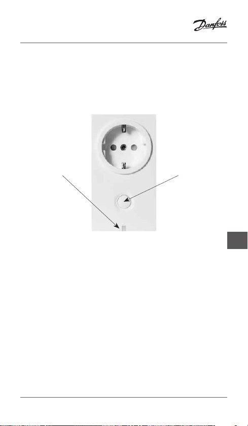
Introduction
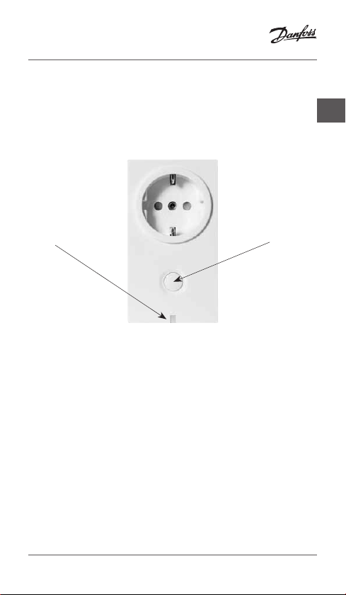
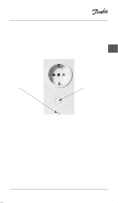
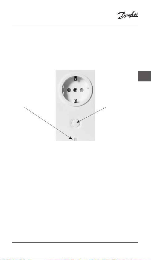
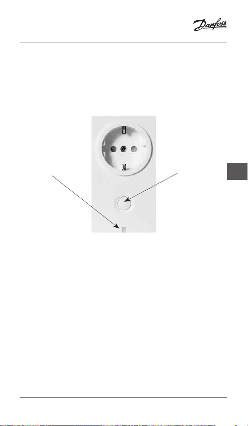
The Danfoss Link™ PR (Plug in relay) is a device for switching heating elements or other electrical equipments ON/
OFF, either manually or by schedule.
GB
LED
The Danfoss Link™ PR Plug in Relay is powered by 230 V~
and is to be installed in a free socket/outlet.
VISGY45X © Danfoss 04/2011
Install/
Link test
5

Installation Guide Danfoss Link™ PR
Installation
The Danfoss Link™ wireless system’s transmission range is
sufficient for most applications; however each building has
different obstacles affecting communication and maximum
transmission distance.
If communication problems occur Danfoss suggests that
accessories would be required to support the system, such as
repeaters. In exceptional cases the wireless system may not be
suitable for your installation.
Please be aware of the following, when installing Danfoss
Link™ PR:
Installation and placement must be according to
local building regulations.
Operation mode
Danfoss Link™ PR supports two types of operation modes:
1. ON/OFF switching.
2. Heating regulation (when using Danfoss Link™ PR as heat-
ing regulation in a room you also have to install a Danfoss
Link™ RS).
Note! Do not install electric floor heating system without
a floor sensor, when the heating element is installed on or
beneath wooden surfaces and other surfaces sensitive to
temperature!
6
VISGY45X © Danfoss 04/2011
Installation Guide Danfoss Link™ PR
Installation
1. Connect Danfoss Link™ PR to a
SCHUCKO socket/outlet.
2. Heating elements connected to
Danfoss Link™ PR have to be self
protective against overheating.
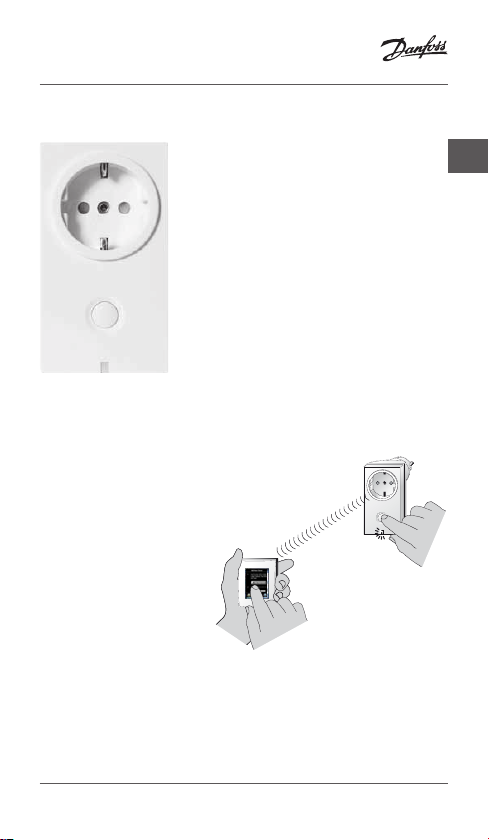
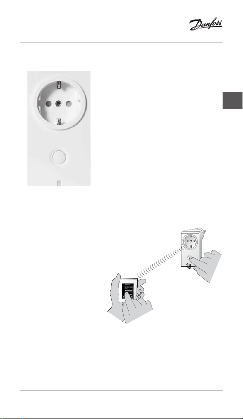
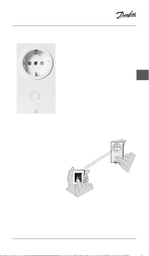
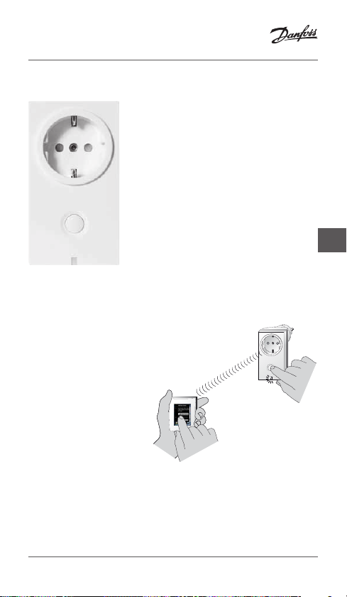
Adding device
Adding Danfoss Link™ PR to a system
is made from the Danfoss Link™ CC
Central Controller.
When adding, press the install
button until the LED gives a
fast green flash.
For further information,
see the Danfoss Link™ CC
instruction manual:
Configuration 6:
Adding devices.
1.
GB
2.
Max. 1 m
VISGY45X © Danfoss 04/2011
7
Installation Guide Danfoss Link™ PR
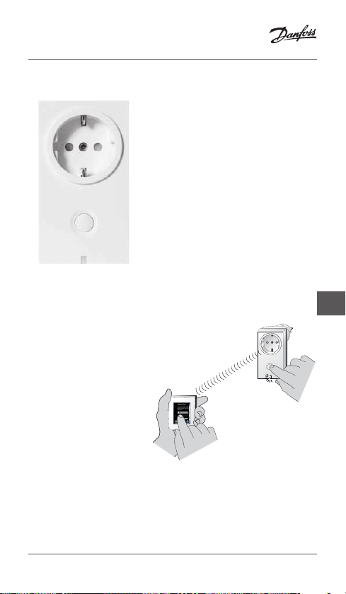
Perform network test
When the Danfoss Link™ PR has been
added to the Danfoss Link™ CC Central
Controller, a network test should be
performed.
For more information on network tests,
see the Danfoss Link™ CC instruction
manual:
Configuration 8:
Perform n etwork test.
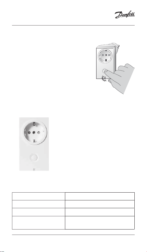
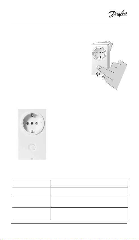
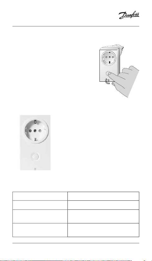
Factory reset
1. Disconnect the unit to cut off power.
Hold the install button down
while reconnecting power. Keep
pressing the install button until
the LED gives a red flash (approx.
5 seconds).
Trouble shooting
Green LED ON Relay OFF/Standby
Red LED ON Relay ON/Heating
Green LED fast flash Inclusion or link test
Red LED short flash Inclusion not OK
Link test not OK
8
VISGY45X © Danfoss 04/2011
Installation Guide Danfoss Link™ PR
Technical specifications
Operation voltage 230 V AC, 50 Hz
Standby consumption <1W
GB
Load
Regulation PWM or ON/OFF
Ambient temperature 0˚ to +35˚C
Transmission frequency
Transmission range in
normal buildings
Transmission power
IP class 20
Dimensions 106 mm × 59 mm × 75 mm
2300 W, 460 VA, 600 W
Incandescent Bulbs
868.42 MHz
Up to 30 m
Max. 1 mW
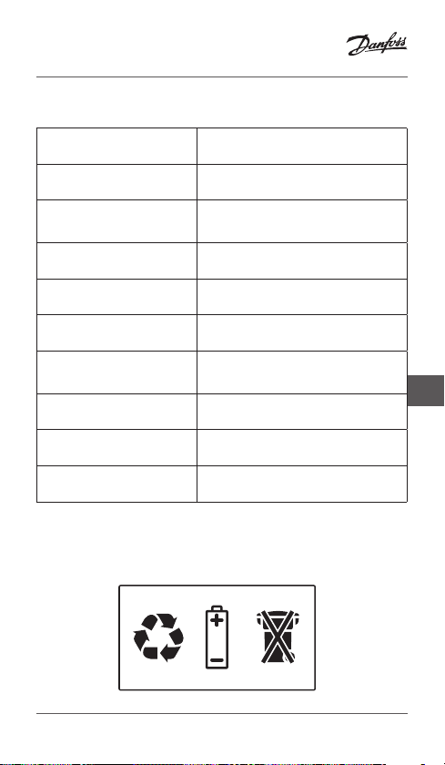
Disposal instructions
VISGY45X © Danfoss 04/2011
9

Installationsanleitung Danfoss Link™ PR
Inhaltsverzeichnis
Einführung . . . . . . . . . . . . . . . . . . . . . . . . . . . . . . . . . . . . . . . . . . . . . . . . 11
Installation. . . . . . . . . . . . . . . . . . . . . . . . . . . . . . . . . . . . . . . . . . . . . . . . 12
Hinzufügen von Geräten
Durchführen eines Netzwerktests
Rücksetzen auf Werkseinstellungen
Fehlersuche und -behebung
Technische Spezifikationen. . . . . . . . . . . . . . . . . . . . . . . . . . . . . . . . 15
Hinweise zur Entsorgung . . . . . . . . . . . . . . . . . . . . . . . . . . . . . . . . . . 15
. . . . . . . . . . . . . . . . . . . . . . . . . . . . . . . . . . 13
. . . . . . . . . . . . . . . . . . . . . . . . . 14
. . . . . . . . . . . . . . . . . . . . . . . 14
. . . . . . . . . . . . . . . . . . . . . . . . . . . . . . 14
10
VISGY45X © Danfoss 04/2011
Installationsanleitung Danfoss Link™ PR
Einführung
Das Danfoss Link™ PR (Steckrelais) ist ein Gerät zum Ein- und
Ausschalten von Heizelementen oder anderen elektrischen
Geräten. Dies kann wahlweise manuell oder zeitgesteuert
erfolgen.
DE
LED
Das Steckrelais Link™ PR von Danfoss wird mit 230 V~ betrieben und muss an eine freie Netzsteckdose angeschlossen
werden.
VISGY45X © Danfoss 04/2011
Installieren/
Verbindungs-
prüfung
11

Installationsanleitung Danfoss Link™ PR
Installation
Der Übertragungsbereich des Funksystems des Danfoss Link™
ist für die meisten Anwendungen ausreichend. Allerdings gibt
es in jedem Gebäude andere Hindernisse, die die Kommunikation und den maximalen Übertragungsbereich beeinträchtigen.
Bei Kommunikationsproblemen empfiehlt Danfoss den Einsatz
von Zubehörteilen wie beispielsweise Verstärkern. In Ausnahmefällen ist das Funksystem für Ihre Installation möglicherweise
nicht geeignet.
Bei der Montage des Danfoss Link™ PR ist Folgendes zu
beachten:
Die Platzierung und Installation muss unter
Beachtung der ör tlichen Bauvorschriften erfolgen.
Betriebsmodus
Das Danfoss Link™ PR unterstützt zwei Betriebsmodi:
1. EIN/AUS-Schalten.
2. Heizungsregelung (Wenn Sie das Danfoss Link™ PR für die
Heizungsregelung in einem Raum einsetzen, müssen Sie
zusätzlich einen Link™ RS von Danfoss installieren).
Hinweis! Wenn das Heizelement eines elektrischen Fußbodenheizsystems auf oder unter Holzflächen oder anderen temperaturempfindlichen Flächen montier t wird, muss in jedem Fall
ein Bodenfühler montiert werden!
12
VISGY45X © Danfoss 04/2011
Installationsanleitung Danfoss Link™ PR
Installation
1. Das Danfoss Link™ PR an eine
Netzsteckdose mit Schutzkontakt
(SCHUKO) anschließen.
2. An das Danfoss Link™ PR angeschlossene Heizelemente müssen
über einen Selbstschutz gegen
Überhitzung verfügen.
Hinzufügen von Geräten
Das Hinzufügen des Danfoss Link™
PR zu einem System erfolgt über den
Zentralregler Link™ CC von Danfoss.
Beim Hinzufügen die Installationstaste gedrückt halten
bis die LED schnell grün
aufblinkt.
Weitere Informationen
finden Sie im Produkthandbuch
zum Danfoss Link™ CC:
Konfiguration 6:
Hinzufügen von Geräten.
1.
DE
2.
Max. 1 m
VISGY45X © Danfoss 04/2011
13
Installationsanleitung Danfoss Link™ PR
Durchführen eines Netzwerktests
Wenn das Danfoss Link™ PR dem Zentralregler Link™ CC von Danfoss hinzugefügt
wurde, sollte ein Netzwerktest durchgeführt werden.
Weitere Informationen zu Netzwerktests
finden Sie im Produkthandbuch zum
Danfoss Link™ CC:
Konfiguration 8:
Durchführen eines Netzwerktests.
Rücksetzen auf Werkseinstellungen
1. Das Relais vom Stromnetz trennen.
Die Installationstaste gedrückt
halten und dabei die Verbindung
zum Stromnetz wiederherstellen.
Die Installationstaste gedrückt
halten bis die LED rot blinkt (ca.
5 Sekunden).
Fehlersuche und -behebung
Grüne LED EIN Relais AUS/Stand-by
Rote LED EIN Relay EIN/Heizung
Grüne LED
blinkt schnell
Rote LED
blinkt kurz
Einbindung oder Verbindungsprüfung
Einbindung fehlgeschlagen
Verbindungsprüfung fehlgeschlagen
14
VISGY45X © Danfoss 04/2011
Installationsanleitung Danfoss Link™ PR
Technische Daten
Betriebsspannung 230 V AC, 50 Hz
Stromverbrauch im
Stand-by-Modus
Last
Regelung PWM oder EIN/AUS
Umgebungstemperatur 0 ° bis +35 °C
Übertragungsfrequenz 868,42 MHz
Übertragungsbereich in
normalen Gebäuden
Übertragungsleistung
IP-Schutzart 20
Abmessungen 106 mm × 59 mm × 75 mm
<1 W
2.300 W, 460 VA, 600 W
Glühlampen
Bis zu 30 m
Max. 1 mW
Hinweise zur Entsorgung
DE
VISGY45X © Danfoss 04/2011
15

Guide d’installation Danfoss Link™ PR
Sommaire
Introduction . . . . . . . . . . . . . . . . . . . . . . . . . . . . . . . . . . . . . . . . . . . . . . 17
Installation. . . . . . . . . . . . . . . . . . . . . . . . . . . . . . . . . . . . . . . . . . . . . . . . 18
Ajout d’une unité. . . . . . . . . . . . . . . . . . . . . . . . . . . . . . . . . . . . . . . . . . 19
Réalisation d’un test du réseau
Réinitialisation aux réglages d’usine
Dépannage
Spécifications techniques
Consignes de mise au rebut
. . . . . . . . . . . . . . . . . . . . . . . . . . . . . . . . . . . . . . . . . . . . . . . 20
. . . . . . . . . . . . . . . . . . . . . . . . . . . . 20
. . . . . . . . . . . . . . . . . . . . . . . 20
. . . . . . . . . . . . . . . . . . . . . . . . . . . . . . . . . 21
. . . . . . . . . . . . . . . . . . . . . . . . . . . . . . . 21
16
VISGY45X © Danfoss 04/2011
Guide d’installation Danfoss Link™ PR
Introduction
Le relais sur prise Danfoss Link™ PR est un dispositif d’activation et de désactivation manuelles ou programmées des
éléments chauffants ou d’autres équipements électriques.
FR
LED
Le relais sur prise Danfoss Link™ PR est alimenté sur 230 V~ et
doit être installé à une prise ou une sortie libre.
VISGY45X © Danfoss 04/2011
d’installation/
Test
liaison
17

Guide d’installation Danfoss Link™ PR
Installation
La portée de transmission du système sans fil Danfoss Link™
suffit pour la plupart des applications. Chaque bâtiment présente toutefois différents obstacles susceptibles d’affecter la
communication et la distance de transmission maximale.
En cas de problèmes de communication, Danfoss préconise
l’emploi d’accessoires tels que des répétiteurs. Dans de rares
cas, il est possible que des installations ne se prêtent pas à
l’utilisation d’un système sans fil.
Lors de l’installation du Danfoss Link™ PR, veuillez tenir
compte des points suivants :
L’installation et le positionnement doivent être
conformes aux réglementations en vigueur.
Mode de fonctionnement
Le Danfoss Link™ PR prend en charge deux types de modes de
fonctionnement :
1. Marche/Arrêt.
2. Régulation du chauffage (lorsque le Danfoss Link™ PR est
utilisé comme régulateur de chauffage dans une pièce, vous
pouvez aussi installer un Danfoss Link™ RS).
Remarque : n’installez pas de système de chauffage au sol
électrique sans sonde de dalle si l’élément chauffant est
installé sur ou sous des sur faces en bois ou d’autres surfaces
sensibles à la chaleur !
18
VISGY45X © Danfoss 04/2011
Guide d’installation Danfoss Link™ PR
Installation
1. Branchez le Danfoss Link™ PR à une
prise/sortie SCHUCKO.
2. Les éléments chauffants branchés
au Danfoss Link™ PR doivent être
autoprotégés contre la surchauffe.
Ajout d’une unité
L’ajout du Danfoss Link™ PR à un
système se fait à partir du régulateur
central Danfoss Link™ CC.
Lors de l’ajout, appuyez sur le
bouton d’installation jusqu’à
ce que le voyant vert
clignote rapidement.
Pour plus d’informations,
voir le mode d’emploi du
Danfoss Link™ CC :
Configuration 6 :
Ajout d’un ités locales.
1.
FR
2.
1 m max.
VISGY45X © Danfoss 04/2011
19

Guide d’installation Danfoss Link™ PR
Réalisation d’un test du réseau
Il convient d’effectuer un test du réseau
une fois le Danfoss Link™ PR ajouté au
régulateur central Danfoss Link™ CC.
Pour de plus amples informations sur les
tests de réseau, voir le mode d’emploi du
Danfoss Link™ CC :
Configuration 8 :
Réalisation d’un te st du réseau.
Réinitialisation aux réglages d’usine
1. Débranchez l’appareil de l’alimen-
tation. Maintenez le bouton d’installation enfoncé lorsque vous rétablissez l’alimentation. Maintenez
le bouton d’installation enfoncé
jusqu’à ce que le voyant rouge
clignote (environ 5 secondes).
Dépannage
Voyant vert allumé
Voyant rouge allumé
Clignotement rapide du
voyant vert
Clignotement rapide du
voyant rouge
Relais arrêté ou en veille
Relais actif/Chauffage
Test d’inclusion ou de liaison
Inclusion incorrecte
Test de liaison incorrect
20
VISGY45X © Danfoss 04/2011

Guide d’installation Danfoss Link™ PR
Caractéristiques techniques
Tension de
fonctionnement
Consommation en veille <1W
230 V CA, 50 Hz
Charge
Régulation PWM ou Marche/Arrêt
Température ambiante
Fréquence de
transmission
Portée de transmission
dans un bâtiment normal
Puissance de transmission
Classe IP 20
Dimensions 106 mm × 59 mm × 75 mm
Ampoules à incandescence
2 300 W, 460 VA, 600 W
0˚ à +35 ˚C
868.42 MHz
Jusqu’à 30 m
Max. 1 mW
Consignes de mise au rebut
VISGY45X © Danfoss 04/2011
FR
21

Installationsmanual Danfoss Link™ PR
Indeks
Introduktion . . . . . . . . . . . . . . . . . . . . . . . . . . . . . . . . . . . . . . . . . . . . . . 23
Installation. . . . . . . . . . . . . . . . . . . . . . . . . . . . . . . . . . . . . . . . . . . . . . . . 24
Tilføjelse af enhed. . . . . . . . . . . . . . . . . . . . . . . . . . . . . . . . . . . . . . . . . 25
Udførelse af netværkstest
Fabriksnulstilling . . . . . . . . . . . . . . . . . . . . . . . . . . . . . . . . . . . . . . . . . . 26
Fejlfinding
Tekniske specifikationer . . . . . . . . . . . . . . . . . . . . . . . . . . . . . . . . . . . 27
Vejledning for bortskaffelse
. . . . . . . . . . . . . . . . . . . . . . . . . . . . . . . . . . . . . . . . . . . . . . . . 26
. . . . . . . . . . . . . . . . . . . . . . . . . . . . . . . . . 26
. . . . . . . . . . . . . . . . . . . . . . . . . . . . . . . 27
22
VISGY45X © Danfoss 04/2011

Installationsmanual Danfoss Link™ PR
Introduktion
Danfoss Link™ PR (relæ til stikdåse) er en enhed til ON/OFFstyring af varmeelementer og andet elektrisk udstyr enten
manuelt eller via tidsstyring.
DK
Lysdiode
Danfoss Link™ PR forsynes med 230 V~ og skal installeres i en
ledig stikkontakt.
VISGY45X © Danfoss 04/2011
Installations-
/Link-test
23

Installationsmanual Danfoss Link™ PR
Installation
Det trådløse systems transmissionsrækkevidde i Danfoss Link™
er tilstrækkelig i de fleste applikationer. Forholdene varierer
dog fra bygning til bygning, hvilket kan påvirke kommunikationen og den maksimale transmissionsafstand.
I tilfælde af kommunikationsproblemer anbefaler Danfoss,
at der tilsluttes tilbehør, som understøtter systemet, f.eks.
repeatere. I meget få tilfælde vil det trådløse system ikke være
egnet til din installation.
Følgende skal overvejes ved installation af Danfoss Link™ PR:
Installation og placering skal stemme overens med
de lokale byggeregulativer.
Driftstilstand
Danfoss Link™ PR understøtter to former for driftstilstande:
1. ON/OFF.
2. Varmeregulering (Hvis Danfoss Link™ PR benyttes til var-
meregulering i et rum, er det også nødvendigt at installere
rumtermostaten Danfoss Link™ RS).
Bemærk! Installer aldrig elektriske gulvvarmesystemer uden
gulvføler, når varmeelementet installe res på eller under overflader af træ elle r andre temperaturfølsomme materialer!
24
VISGY45X © Danfoss 04/2011

Installationsmanual Danfoss Link™ PR
Installation
1. Forbind Danfoss Link™ PR med en
stikkontakt.
2. Varmeelementer med forbindelse
til Danfoss Link™ PR skal være selvbeskyttende mod overophedning.
Tilføjelse af enhed
Tilføjelse af Danfoss Link™ PR til et
system foretages via Danfoss Link™ CC
Central Controller.
Ved tilføjelse skal der trykkes på
installationsknappen, indtil
lysdioden blinker grønt
hurtigt.
Yderligere oplysninger
fremgår af instruktionsmanualen til
Danfoss Link™ CC:
Konfiguration 6:
Tilføje lse af enheder.
1.
DK
2.
Maks. 1 m
VISGY45X © Danfoss 04/2011
25
Installationsmanual Danfoss Link™ PR
Udførelse af netværkstest
Når Danfoss Link™ PR er føjet til Danfoss
Link™ CC Central Controller, skal der udføres en netværkstest.
Du kan få flere oplysninger om netværkstest i instruktionsmanualen til Danfoss
Link™ CC:
Konfiguration 8:
Udførelse af netværkste st.
Fabriksnulstilling
1. Afbryd enheden for at slukke for
strømmen. Hold installationsknappen inde, mens der tændes for
strømmen igen. Hold installationsknappen inde, indtil lysdioden
blinker rødt (ca. 5 sekunder).
Fejlfinding
Grøn lysdiode ON
Rød lysdiode ON
Grøn lysdiode blinker
hurtigt
Rød lysdiode blinker
kortvarigt
Relæ OFF (SLUKKET/Standby)
Relæ ON (TÆNDT/Opvarmning)
Tilmeldings- eller linktest
Tilmelding ikke i orden
Linktest ikke i orden
26
VISGY45X © Danfoss 04/2011
Installationsmanual Danfoss Link™ PR
Tekniske specifikationer
Driftsspænding 230 V AC, 50 Hz
Standbyforbrug <1 W
Belastning
Regulering PWM eller ON/OFF
Omgivelsestemperatur 0˚ til +35˚ C
Transmissionsfrekvens 868,42 MHz
Transmissionsrækkevidde
i normale bygninger
Transmissionseffekt
IP-klasse 20
Dimensioner 106 mm × 59 mm × 75 mm
2.300 W, 460 VA, 600 W
glødepærer
Op til 30 m
Maks. 1 mW
Vejledning for bortskaffelse
VISGY45X © Danfoss 04/2011
DK
27

Installationshandbok Danfoss Link™ PR
Innehåll
Introduktion . . . . . . . . . . . . . . . . . . . . . . . . . . . . . . . . . . . . . . . . . . . . 29
Installation. . . . . . . . . . . . . . . . . . . . . . . . . . . . . . . . . . . . . . . . . . . . . . 30
Lägga till en enhet . . . . . . . . . . . . . . . . . . . . . . . . . . . . . . . . . . . . . . 31
Genomföra ett nätverkstest . . . . . . . . . . . . . . . . . . . . . . . . . . . . . 32
Fabriksåterställning . . . . . . . . . . . . . . . . . . . . . . . . . . . . . . . . . . . . . 32
Felsökning . . . . . . . . . . . . . . . . . . . . . . . . . . . . . . . . . . . . . . . . . . . . . . 32
Tekniska specifikationer . . . . . . . . . . . . . . . . . . . . . . . . . . . . . . . . . 33
Instruktioner för återvinning . . . . . . . . . . . . . . . . . . . . . . . . . . . . 33
28
VISGY45X © Danfoss 04/2011
Installationshandbok Danfoss Link™ PR
Introduktion
Danfoss Link™ PR är ett stickkontaktsrelä som används för
att slå på och av värmeelement eller annan elektrisk utrustning, antingen manuellt eller schemalagt.
Lysdiod
Stickkontaktsreläet Danfoss Link™ PR drivs med 230 V~ och
installeras i ett uttag som är ledigt.
VISGY45X © Danfoss 04/2011
Installation/
förbindelsetest
SE
29

Installationshandbok Danfoss Link™ PR
Installation
I de flesta fall är överföringsområdet för det trådlösa Danfoss
Link™-systemet fullt tillräckligt, men i alla byggnader finns
det olika hinder som kan påverka kommunikationen och det
maximala överföringsavståndet.
Om det uppstår problem med kommunikationen behöver
systemet antagligen stödjas av någon typ av tillbehör, till
exempel förstärkare. I undantagsfall går det inte att använda
det trådlösa systemet.
Tänk på följande när du installerar stickkontaktsreläet
Danfoss Link™ PR:
Reläet måste installeras och placeras i enlighet med
de lokala byggnadsföreskrifterna.
Driftsläge
Stickkontaktsreläet Danfoss Link™ PR stödjer två typer av
driftslägen:
1. PÅ/AV-slagning
2. Värmereglering: När du använder stickkontaktsreläet
Danfoss Link™ PR för att reglera värmen i ett rum måste du
också installera en rumsgivare av typen Danfoss Link™ RS.
Obs! Installera aldrig ett elektriskt golvvärmesystem utan
golvgivare när värmeelementet är monterat på eller under
en träyta, eller på någon annan yta som är temperaturkänslig!
30
VISGY45X © Danfoss 04/2011
Installationshandbok Danfoss Link™ PR
Installation
1. Sätt i stickproppsreläet Danfoss
Link™ PR i ett SCHUCKO-uttag.
2. Alla värmeelement som du ansluter till Danfoss Link™ PR-stickproppsreläet måste ha ett inbyggt
överhettningsskydd.
Lägga till en enhet
Du lägger till Danfoss Link™ PRstickproppsreläet i ett system via
styrenheten Danfoss Link™ CC.
När du lägger till reläet håller
du installationsknappen
intryckt tills lysdioden
börjar blinka snabbt och
grönt.
Mer information finns i
installationshandboken
för styrenheten Danfoss
Link™ CC:
Konfiguration 6:
Lägga till rumsenheter.
1.
SE
2.
Max. 1 m
VISGY45X © Danfoss 04/2011
31

Installationshandbok Danfoss Link™ PR
Genomföra ett nätverkstest
När du har lagt till Danfoss Link™
PR-stickproppsreläet i styrenheten
Danfoss Link™ CC bör du genomföra ett
nätverkstest.
Mer information finns i installationshandboken för Danfoss Link™ CC-styrenheten:
Konfiguration 8:
Genomföra ett nät verkstest.
Fabriksåterställning
1. Ta bort enheten från uttaget så
att strömförsörjningen bryts. Håll
installationsknappen intryckt
samtidigt som du sätter tillbaka
enheten i uttaget. Fortsätt att
hålla installationsknappen intryckt
tills lysdioden börjar blinka rött (i
ungefär 5 sekunder).
Felsökning
Grön lysdiod PÅ Relä AV / i vänteläge
Röd lysdiod PÅ Relä PÅ / värme
Snabbt blinkande grön
lysdiod
Kort blinkande röd
lysdiod
32
Inkludering eller
förbindelsetest
Inkludering inte OK
Förbindelsetest inte OK
VISGY45X © Danfoss 04/2011

Installationshandbok Danfoss Link™ PR
Tekniska specifikationer
Driftspänning 230 V AC, 50 Hz
Förbrukning i vänteläge < 1W
Belastning
Reglering PWM eller PÅ/AV
Omgivande temperatur 0 ˚C till + 35 ˚C
Överföringsfrekvens 868,42 MHz
Överföringsområde i
vanliga byggnader
Överföringseffekt
IP-klass 20
Mått 106 mm × 59 mm × 75 mm
2 300 W, 460 VA,
600 W-glödlampor
upp till 30 m
Max. 1 mW
Instruktioner för återvinning
VISGY45X © Danfoss 04/2011
SE
33

Asennusohje Danfoss Link™ PR
Sisällys
Johdanto . . . . . . . . . . . . . . . . . . . . . . . . . . . . . . . . . . . . . . . . . . . . . . . . . 35
Asennus
. . . . . . . . . . . . . . . . . . . . . . . . . . . . . . . . . . . . . . . . . . . . . . . . . . 36
Laitteiden lisääminen
Verkon testaaminen . . . . . . . . . . . . . . . . . . . . . . . . . . . . . . . . . . . . . . . 38
Tehdasasetusten palauttaminen. . . . . . . . . . . . . . . . . . . . . . . . . . . 38
Vianmääritys . . . . . . . . . . . . . . . . . . . . . . . . . . . . . . . . . . . . . . . . . . . . . . 38
Tekniset tiedot
Hävittäminen
. . . . . . . . . . . . . . . . . . . . . . . . . . . . . . . . . . . . . 37
. . . . . . . . . . . . . . . . . . . . . . . . . . . . . . . . . . . . . . . . . . . . 39
. . . . . . . . . . . . . . . . . . . . . . . . . . . . . . . . . . . . . . . . . . . . . 39
34
VISGY45X © Danfoss 04/2011

Asennusohje Danfoss Link™ PR
Johdanto
Danfoss Link™ PR (pistorasialähetin) on laite, jolla voi kytkeä
lämmityselementtejä tai muita sähkölaitteita päälle/pois, joko
manuaalisesti tai tietyn aikataulun mukaan.
LED-valo
Danfoss Link™ PR -pistorasialähetin toimii 230 V~ jännitteellä,
ja se tulee asentaa vapaaseen pistorasiaan.
VISGY45X © Danfoss 04/2011
Asennus/
yhteys-testi
FI
35

Asennusohje Danfoss Link™ PR
Asennus
Langattoman Danfoss Link™ -järjestelmän kantama riittää
useimmille sovelluksille, mutta kaikissa rakennuksissa on omat
esteensä, jotka vaikuttavat viestintään ja enimmäiskantamaan.
Jos viestintäongelmia esiintyy, Danfoss kehottaa harkitsemaan
lisävarusteita, kuten toistimia, järjestelmän tukena. Joihinkin
harvoihin kohteisiin langaton järjestelmä ei sovellu.
Ota huomioon seuraavat seikat Danfoss Link™ PR:n asennuksen
yhteydessä:
Asennuksessa ja laitteen sijoittamisessa on
noudatettava paikallisia rakennusmääräyksiä.
Käyttötila
Danfoss Link™ PR tukee kahta eri käyttötilaa:
1. Kytkeminen päälle/pois.
2. Lämmityksen säätely (kun Danfoss Link™ PR -pistorasialä-
hetintä käytetään huoneen lämmityksen säätelyyn, lisäksi
on asennettava Danfoss Link™ RS).
Huomautus! Älä asenna sähkökäyttöistä lattialämmitysjärjestelmää ilman lattia-anturia, kun lämpöelementti on asennettu
puulattian tai muun lämpötilalle herkän lattian päälle tai alle!
36
VISGY45X © Danfoss 04/2011

Asennusohje Danfoss Link™ PR
Asennus
1. Kytke Danfoss Link™ PR SCHUCKOpistorasiaan.
2. Danfoss Link™ PR -pistorasialähettimeen kytketyissä lämmityselementeissä on oltava ylikuumenemissuojaus.
Laitteiden lisääminen
Danfoss Link™ PR lisätään järjestelmään Danfoss Link™ CC -keskusyksiköstä.
Lisää laite painamalla asennuspainiketta, kunnes LED
vilkkuu nopeasti vihreänä.
Lisätiedot, katso Danfoss
Link™ CC -käyttöohje:
Konfigurointi 6:
Laittei den lisääminen.
1.
FI
2.
Enint. 1 m
VISGY45X © Danfoss 04/2011
37

Asennusohje Danfoss Link™ PR
Verkon testaaminen
Kun Danfoss Link™ PR -pistorasialähetin
on liitetty Danfoss Link™ CC -keskusyksikköön, on suoritettava verkkotesti.
Lisätietoja verkon testauksesta saat
Danfoss Link™ CC -käyttöohjeesta:
Konfigurointi 8:
Testaa verkko.
Tehdasasetusten palauttaminen
1. Kytke laite irti virran katkaisemisek-
si. Pidä asennuspainiketta pohjassa
kytkiessäsi virran uudelleen. Paina
asennuspainiketta, kunnes LEDvalo vilkahtaa punaisena (noin 5
sekuntia).
Vianmääritys
Vihreä LED palaa Rele pois päältä / valmiustila
Punainen LED palaa Rele päällä / lämmitys
Vihreä LED vilkkuu
nopeasti
Punainen LED vilkkuu
lyhyesti
Liittäminen tai yhteyden testaus
Liittäminen ei OK
Yhteystesti ei OK
38
VISGY45X © Danfoss 04/2011

Asennusohje Danfoss Link™ PR
Tekniset tiedot
Käyttöjännite 230 V AC, 50 Hz
Valmiustilan kulutus <1 W
Kuormitus
Säätely PWM tai päälle/pois
Käyttölämpötila 0 - +35˚C
Lähetys-taajuus 868,42 MHz
Kantama tavallisissa
rakennuksissa
Lähetysteho
IP-luokka 20
Mitat 106 mm × 59 mm × 75 mm
2300 W, 460 VA, 600 W
hehkulamput
Enintään 30 m
Enint. 1 mW
Hävittäminen
VISGY45X © Danfoss 04/2011
FI
39

Installatiehandleiding Danfoss Link™ PR
Inhoud
Inleiding . . . . . . . . . . . . . . . . . . . . . . . . . . . . . . . . . . . . . . . . . . . . . . . . . . 41
Installatie
Apparaat toevoegen
Netwerktest uitvoeren
Herstellen van fabrieksinstellingen . . . . . . . . . . . . . . . . . . . . . . . . 44
Problemen verhelpen
Technische specificaties . . . . . . . . . . . . . . . . . . . . . . . . . . . . . . . . . . . 45
Instructies voor afvoer
. . . . . . . . . . . . . . . . . . . . . . . . . . . . . . . . . . . . . . . . . . . . . . . . . 42
. . . . . . . . . . . . . . . . . . . . . . . . . . . . . . . . . . . . . . 43
. . . . . . . . . . . . . . . . . . . . . . . . . . . . . . . . . . . . 44
. . . . . . . . . . . . . . . . . . . . . . . . . . . . . . . . . . . . . 44
. . . . . . . . . . . . . . . . . . . . . . . . . . . . . . . . . . . . 45
40
VISGY45X © Danfoss 04/2011

Installatiehandleiding Danfoss Link™ PR
Inleiding
De Danfoss Link™ PR (Plug-in Relay – stekkerrelais) is een apparaat voor het in- en uitschakelen van verwarmingselementen
of andere apparatuur, handmatig of volgens schema.
Led
De Danfoss Link™ PR wordt gevoed via 230 V~ en moet worden
geïnstalleerd in een vrij stopcontact.
VISGY45X © Danfoss 04/2011
Installatie-
/verbindings-
test
NL
41

Installatiehandleiding Danfoss Link™ PR
Installatie
Het zendbereik van het draadloze systeem Danfoss Link™
volstaat voor de meeste toepassingen. Elk gebouw heeft
echter verschillende obstakels die van invloed zijn op de communicatie en het maximale zendbereik.
Danfoss adviseert om bij communicatieproblemen accessoires
te gebruiken om het systeem te ondersteunen, zoals versterkers. In uitzonderlijke gevallen bestaat de mogelijkheid dat
het draadloze systeem niet geschikt is voor uw installatie.
Let op het volgende wanneer u Danfoss Link™ PR installeert:
Installatie en plaatsing moeten worden uitgevoerd
overeenkomstig de plaatselijke bouw voorschriften.
Bedrijfsmodus
Danfoss Link™ PR ondersteunt twee bedrijfsmodi:
1. IN/UIT-schakeling.
2. Verwarmingsregeling: wanneer Danfoss Link™ PR als
warmteregeling voor een ruimte wordt gebruikt, moet u
tevens een Danfoss Link™ RS installeren.
NB! Installeer geen elektrisch vloerver warmingssysteem zonder vloersensor als het verwarmingselement is geïnstalleerd
op of onder een houten opper vlak of andere oppervlakken die
temperatuurgevoelig zijn!
42
VISGY45X © Danfoss 04/2011
Installatiehandleiding Danfoss Link™ PR
Installatie
1. Sluit de Danfoss Link™ PR aan op
een Schuko-stopcontact.
2. Verwarmingselementen die op een
Danfoss Link™ PR worden aangesloten, moeten een eigen beveiliging
tegen oververhitting hebben.
Apparaat toevoegen
Het toevoegen van de Danfoss Link™
PR aan een systeem gebeurt via de
Danfoss Link™ CC Centrale Regelaar.
Druk hiervoor de installatieknop
in totdat de led snel groen
gaat knipperen.
Meer informatie is te
vinden in de Danfoss
Link™ CC:
Configuratie 6:
Apparaten toevoegen.
VISGY45X © Danfoss 04/2011
1.
NL
2.
Max. 1 m
43

Installatiehandleiding Danfoss Link™ PR
Netwerktest uitvoeren
Wanneer de Danfoss Link™ PR aan de
Danfoss Link™ CC Centrale Regelaar is
toegevoegd, moet een netwerktest worden uitgevoerd.
Meer informatie over netwerktests is te
vinden in de Danfoss Link™ CC instructiehandleiding:
Configuratie 8:
Netwerktest uitvoeren.
Herstellen van fabrieksinstellingen
1. Koppel de eenheid los van de
voeding. Houd de installatieknop
ingedrukt terwijl u de spanning
weer inschakelt. Houd de installatieknop ingedrukt totdat de led
rood gaat knipperen (na ongeveer
5 seconden).
Problemen verhelpen
Groene led AAN Relais uit/stand-by
Rode led AAN Relais AAN/verwarmen
Groene led knippert snel Opname in netwerk of
Rode led licht kort op Opname in netwerk mislukt
verbindingstest
Verbindingstest mislukt
44
VISGY45X © Danfoss 04/2011
Installatiehandleiding Danfoss Link™ PR
Technische specificaties
Bedrijfsspanning 230 V AC, 50 Hz
Stand-byverbruik < 1 W
Belasting
Regeling PPM of AAN/UIT
Omgevingstemperatuur 0 tot +35 °C
Transmissiefrequentie 868,42 MHz
Transmissiebereik in
normale gebouwen
Transmissievermogen
IP-klasse 20
Afmetingen 106 mm × 59 mm × 75 mm
2300 W, 460 VA, 600 W
gloeilampen
Tot 30 m
Max. 1 mW
Instructies voor afvoer
VISGY45X © Danfoss 04/2011
NL
45

Instrukcja instalacji Danfoss Link™ PR
Spis treści
Wstęp. . . . . . . . . . . . . . . . . . . . . . . . . . . . . . . . . . . . . . . . . . . . . . . . . . . . . 47
Instalacja. . . . . . . . . . . . . . . . . . . . . . . . . . . . . . . . . . . . . . . . . . . . . . . . . . 48
Dodawanie urządzenia . . . . . . . . . . . . . . . . . . . . . . . . . . . . . . . . . . . . 49
Sprawdzenie sieci
Przywracanie ustawień fabrycznych . . . . . . . . . . . . . . . . . . . . . . . 50
Rozwiązywanie problemów
Specyfikacje techniczne. . . . . . . . . . . . . . . . . . . . . . . . . . . . . . . . . . . 51
Instrukcje usuwania
. . . . . . . . . . . . . . . . . . . . . . . . . . . . . . . . . . . . . . . . . 50
. . . . . . . . . . . . . . . . . . . . . . . . . . . . . . . 50
. . . . . . . . . . . . . . . . . . . . . . . . . . . . . . . . . . . . . . . 51
46
VISGY45X © Danfoss 04/2011
Instrukcja instalacji Danfoss Link™ PR
Wstęp
Danfoss Link™ HR (przekaźnik gniazdkowy) jest urządzeniem
służącym do włączania i wyłączania elementów grzejnych
ręcznie lub w zaprogramowany sposób.
Dioda LED
Przekaźnik gniazdkowy Danfoss Link™ PR jest zasilany prądem
o napięciu 230 V~ i należy go instalować w wolnym gniazdku
zasilania.
VISGY45X © Danfoss 04/2011
Test instalacji
/połączenia
PL
47

Instrukcja instalacji Danfoss Link™ PR
Instalacja
Zasięg transmisji systemu bezprzewodowego Danfoss Link™
jest wystarczający dla większości zastosowań; jednak w każdym
budynku znajdują się różnorodne przeszkody, wpływające na
komunikację i maksymalny zasięg.
W razie wystąpienia problemów z komunikacją, Danfoss
zaleca zastosowanie w układzie urządzeń wspomagających,
takich jak wzmacniaki. W wyjątkowych wypadkach system
bezprzewodowy może nie być odpowiedni do danej instalacji.
Proszę mieć na uwadze następujące kwestie przy instalowaniu
Danfoss Link™ PR:
Instalacja i położenie urządzenia muszą spełniać
wymagania lokalnych przepisów budowlanych.
Tryb pracy
Danfoss Link™ PR ma dwa rodzaje trybów pracy:
1. Włączanie i wyłączanie.
2. Regulacja ogrzewania: używając Danfoss Link™ PR w roli
regulatora ogrzewania w pomieszczeniach, należy również
zainstalować Danfoss Link™ RS.
Uwaga! Nie wolno instalować elektr ycznego ogrzewania
podłogowego bez czujnika podłogowego, gdy element
grzewczy jest zainstalowany pod powierzchnią drewnianą lub
inną wrażliwą na wysokie temperatur y!
48
VISGY45X © Danfoss 04/2011

Instrukcja instalacji Danfoss Link™ PR
Instalacja
1. Podłączyć Danfoss Link™ PR do
gniazdka SCHUCKO.
2. Elementy grzejne podłączone
do Danfoss Link™ PR muszą być
samodzielnie zabezpieczone przed
przegrzaniem.
Dodawanie urządzenia
Przekaźnik Danfoss Link™ PR dodaje
się do systemu z poziomu sterownika
centralnego Danfoss Link™ CC.
Podczas dodawania urządzenia
należy nacisnąć i przytrzymać przycisk instalacji, aż
dioda LED zacznie szybko
migać na zielono.
Więcej informacji znajduje
się w instrukcji obsługi
Danfoss Link™ CC:
Konfiguracj a 6:
Dodawan ie urządzeń.
1.
2.
Maks. 1 m
PL
VISGY45X © Danfoss 04/2011
49

Instrukcja instalacji Danfoss Link™ PR
Sprawdzenie sieci
Po dodaniu Danfoss Link™ PR z poziomu
sterownika centralnego Danfoss Link™ CC
należy wykonać sprawdzenie sieci.
Więcej informacji na temat sprawdzania
sieci znajduje się w instrukcji obsługi
Danfoss Link™ CC:
Konfiguracj a 8:
Sprawdzenie sieci.
Przywracanie ustawień fabrycznych
1. Odłączyć urządzenie, aby odciąć
zasilanie. Podczas ponownego
podłączania zasilania należy przytrzymać przycisk instalacji. Przycisk
instalacji należy przytrzymywać aż
dioda LED zamiga na czerwono (ok.
5 sekund).
Rozwiązywanie problemów
Dioda LED świeci na zielono Przekaźnik WYŁ./tryb gotowości
Dioda LED świeci na
czerwono
Dioda LED szybko miga na
zielono
Dioda LED krótko miga na
czerwono
Przekaźnik WŁ./Grzanie
Włączanie do instalacji lub test
połąc zenia
Włączanie do instalacji nie
powiodło się
Test połączenia nie powiódł się
50
VISGY45X © Danfoss 04/2011

Instrukcja instalacji Danfoss Link™ PR
Specyfikacje techniczne
Napięcie robocze 230 V AC, 50 Hz
Pobór mocy w trybie
gotowości
Obciążenie
Regulacja
Temperatura otoczenia od 0˚ do +35˚C
Częstotliwość transmisji 868,42 MHz
Zasięg transmisji w
zwykłych budynkach
Moc transmisji
Klasa IP 20
Wymiary 106 mm x 59 mm x 75 mm
< 1W
2300 W, 460 VA, 600 W Żarówki
włóknowe
PWM lub WŁ./WYŁ.
do 30 m
Maks. 1 mW
Instrukcje usuwania
PL
VISGY45X © Danfoss 04/2011
51

Instalační příručka Danfoss Link™ PR
Obsah
Úvod. . . . . . . . . . . . . . . . . . . . . . . . . . . . . . . . . . . . . . . . . . . . . . . . . . . . . . 53
Instalace
. . . . . . . . . . . . . . . . . . . . . . . . . . . . . . . . . . . . . . . . . . . . . . . . . . 54
Přidání zařízení. . . . . . . . . . . . . . . . . . . . . . . . . . . . . . . . . . . . . . . . . . . . 55
Test sítě . . . . . . . . . . . . . . . . . . . . . . . . . . . . . . . . . . . . . . . . . . . . . . . . . . . 56
Obnovení továrních nastavení. . . . . . . . . . . . . . . . . . . . . . . . . . . . . 56
Řešení problémů . . . . . . . . . . . . . . . . . . . . . . . . . . . . . . . . . . . . . . . . . . 56
Technické údaje . . . . . . . . . . . . . . . . . . . . . . . . . . . . . . . . . . . . . . . . . . . 57
Pokyny k likvidaci
. . . . . . . . . . . . . . . . . . . . . . . . . . . . . . . . . . . . . . . . . 57
52
VISGY45X © Danfoss 04/2011

Instalační příručka Danfoss Link™ PR
Úvod
Zásuvné relé Danfoss Link™ PR (Plug in relay) je prvek, který
slouží k ručnímu nebo naplánovanému zapínání a vypínání
topných těles nebo jiných elektrických zařízení.
Kontrolka
Zásuvné relé Danfoss Link™ PR je napájeno síťovým napětím
230 V~ a instaluje se do volné el. zásuvky.
VISGY45X © Danfoss 04/2011
Instalace/
test spojení
CZ
53

Instalační příručka Danfoss Link™ PR
Instalace
Dosah bezdrátového systému je ve většině případů Danfoss
Link™ dostačující. Nicméně, v každé budově se vysk ytují různé
překážky bránící komunikaci a omezující maximální dosah.
Pokud dochází k potížím s komunikací, společnost Danfoss
doporučuje použít pro podporu systému vhodné příslušenství, např. zesilovače. Ve výjimečných případech nemusí být
bezdrátový systém pro vaši instalaci vhodný.
Při instalaci zásuvného relé Danfoss Link™ PR dodržujte následující pravidla:
Instalace a umístění musí odpovídat místním
stavebním předpisům.
Provozní režim
Relé Danfoss Link™ PR podporuje dva typy provozního režimu:
1. Zapínání a vypínání.
2. Regulace vytápění: Při použití zásuvného relé Danfoss
Link™ PR pro regulaci vytápění v místnosti je potřeba nainstalovat také pokojový termostat Danfoss Link™ RS.
Poznámka: Neinstalujte elek trické podlahové vytápění
bez podlahového čidla, když je topné těleso instalováno v
dřevěném povrchu neb o pod ním nebo v podobných površích
citlivých na teplotu!
54
VISGY45X © Danfoss 04/2011

Instalační příručka Danfoss Link™ PR
Instalace
1. Zapojte zásuvné relé Danfoss
Link™ PR do el. zásuvky SCHUCKO.
2. Topná tělesa připojená k zásuvnému relé Danfoss Link™ PR musí mít
vlastní ochranu proti přehřátí.
Přidání zařízení
Relé Danfoss Link™ PR se připojuje k
systému pomocí centrálního ovladače
Danfoss Link™ CC.
Při přidávání stiskněte instalační
tlačítko a podržte ho, dokud
kontrolka rychle zeleně
nezabliká.
Další informace naleznete v
návodu k použití ovladače
Danfoss Link™ CC:
Konfigurace 6:
Přidávání zařízení.
1.
2.
CZ
Max. 1 m
VISGY45X © Danfoss 04/2011
55

Instalační příručka Danfoss Link™ PR
Test sítě
Po přidání zásuvného relé Danfoss Link™
PR do centrálního ovladače Danfoss Link™
CC proveďte test sítě.
Další informace o testech sítě naleznete
v návodu k použití ovladače Danfoss
Link™ CC:
Konfigurace 8:
Test sítě.
Obnovení továrních nastavení
1. Odpojte relé od napájení. Během
opětovného připojování k napájení
držte stisknuté instalační tlačítko.
Držte instalační tlačítko stisknuté,
dokud kontrolka červeně nezabliká
(přibl. po dobu 5 sekund).
Řešení problémů
Kontrolka svítí zeleně Relé vypnuto/pohotovostní
Kontrolka svítí červeně Relé zapnuto/Systém topí
Kontrolka rychle
zeleně bliká
Kontrolka rychle
červeně bliká
režim
Probíhá přidávání nebo test
spojení
Přidání neproběhlo v pořádku
Test spojení neproběhl v pořádku
56
VISGY45X © Danfoss 04/2011

Instalační příručka Danfoss Link™ PR
Technické údaje
Pracovní napětí 230 V AC, 50 Hz
Spotřeba v
pohotovostním režimu
Zatížení 2300 W, 460 VA, 600 W žárovky
Regulace
Teplota okolí 0 až +35 ˚C
Vysílací frekvence 868,42 MHz
Dosah v normálních
budovách
Přenosový výkon
Třída IP 20
Rozměry 106 × 59 × 75 mm
<1 W
modulace šířkou impulzů nebo
zapnutí/vypnutí
Do 30 m
Max. 1 mW
Pokyny k likvidaci
CZ
VISGY45X © Danfoss 04/2011
57

58
VISGY45X © Danfoss 04/2011

VISGY45X © Danfoss 04/2011
59

Danfoss A/S
Heating Solutions
Haarupvaenget 11
8600 Silkeborg
Denmark
Phone: +45 7488 8000
Fax: +45 7488 8100
Email: heating.solutions@danfoss.com
www.heating.danfoss.com
ARTICL E NO. 088L0437 VISGY45X © Danfoss 04/2011
 Loading...