

Page 1
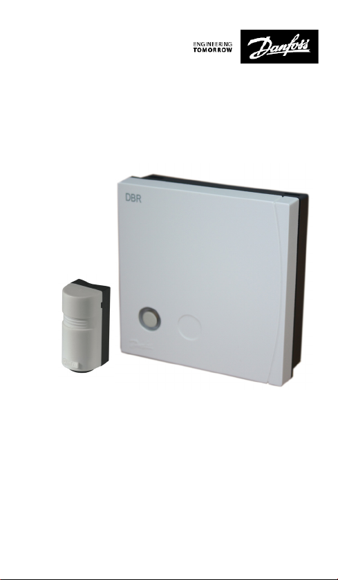
Danfoss Link™ Dynamic Boiler Relay
Installation Guide
Danfoss Heating
Page 2
Installation Guide Danfoss Link™ DBR
UK
UK
NL
FR
Hearby, Danfoss A/S declares that the radio equipment type Danfoss Link DBR is in compliance
with directive 2014/53/EU.
The full text of the EU declaration of conformity is available at the following internet address, http://
heating.danfoss.co.uk
Danfoss can accept no responsibility for possible errors in catalogues, brochures, and other printed
material. All trademarks in this material are property of the respective companies. Danfoss and the
Danfoss logotype are trademarks of Danfoss A/S. All rights reserved.
2
VIIOS202 © Danfoss 07/2017
Page 3

Table of Contents
Introduction.................................................. 4
Installation ................................................... 4
Installation in application with bypass valve using AVDO....... 5
Mounting .................................................... 6
Wiring ....................................................... 7
Adding the device ............................................ 7
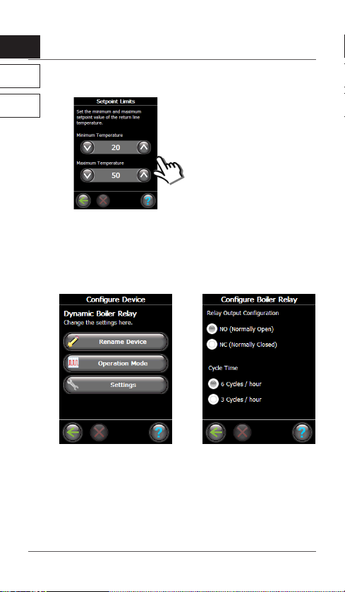
Congure Danfoss Link™ DBR ................................. 8
Congure the DBR Operation Mode........................... 9
Congure the DBR Settings .................................. 10
Perform network test . . . . . . . . . . . . . . . . . . . . . . . . . . . . . . . . . . . . . . . . 11
Factory reset ................................................ 11
Status indicator.............................................. 11
Technical specications...................................... 12
Disposal instructions ........................................ 12
Important information
For safety reasons the heating system must have a bypass
function. This is either built into the boiler or it must be
installed in the system.
Demount other heating control timers in the installation or
they will interfere with the Danfoss Link™ heating control
algorithm. If weather compensation is present it should be set
to constant comfort.
Electric heating devices are not supported.
VIIOS202 © Danfoss 07/2017
3
Page 4
Installation Guide Danfoss Link™ DBR
UK
NL
Introduction
The Danfoss Link™ Dynamic Boiler Relay (DBR) is an electronic
FR
device for turning gas and oil boilers ON/OFF depending on
heat demand.
The Danfoss Link™ DBR must in applications with bypass valve
such as AVDO, be installed in combination with the ESM-11
temperature sensor (included inside the box) for turning the
boiler ON/OFF based on heating demand and water temperature in return pipe for running the system at optimal energy
efficiency.
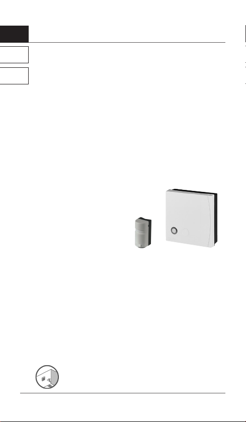
This pack includes:
1 x Danfoss Link™ Dynamic Boiler Relay
1 x ESM-11 Temperature Sensor
Installation
The Danfoss Link™ wireless system’s transmission range is sucient for most applications; however each building has dierent
obstacles aecting communication and maximum transmission
distance. If communication problems occur Danfoss suggests
that accessories would be required to support the system, such
as repeaters.
In exceptional cases the wireless system may not be suitable for
your installation.
Be aware that installation and placement must be
according to local building regulations.
4
VIIOS202 © Danfoss 07/2017
Page 5
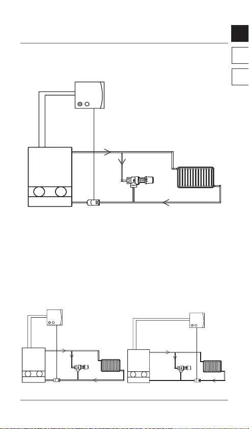
UK
Condensing
Boiler
Bypass
Valve
(AVDO)
Dynamic Boiler
Relay (DBR)
ESM-11
Temperature
Sensor
70C
70C
50C
50C
Condensing
Boiler
Bypass
Valve
(AVDO)
Dynamic Boiler
Relay (DBR)
ESM-11
Temperature
Sensor
70C
70C
50C
50C
Condensing
Boiler
Dynamic Boiler
Relay (DBR)
70C
70C
50C
50C
Bypass
Valve
(AVDO)
ESM-11
Temperature
Sensor
Installation in application with bypass valve
using AVDO
In installations with bypass using AVDO, remember to mount
and wire the ESM-11 Temperature Sensor included in the pack.
Note:
· The ESM-11 Temperature Sensor needs to b e mounted on the
return pipe.
·Mount t he ESM-11 Tempe rature Sensor in the bypass circuit
(gure 1) and not outside of the circuit (gure 2). Pay at tention
that the ESM -11 must be o utside the circuit of an e ventual storage tank
Figure 1
Figure 2
VIIOS202 © Danfoss 07/2017
NL
FR
5
Page 6
Installation Guide Danfoss Link™ DBR
UK
NL
The Danfoss Link™ DBR is not recommended in application
FR
without bypass valve. Install Danfoss Link™ DBR together with
e.g. AVDO bypass valve.
If boiler has internal bypass valve and installed with weather
compensation, the Danfoss Link™ DBR can be installed without
the Return Sensor, in operation mode “On when Heat Demand”
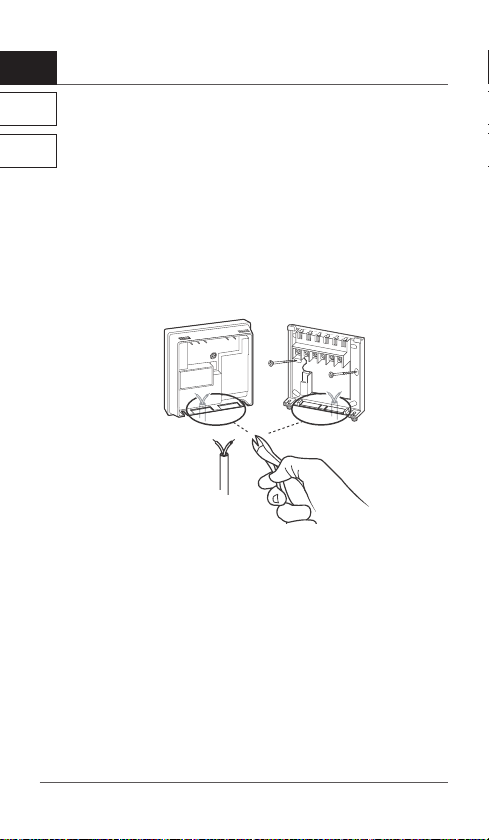
Mounting
Note:
The Danfoss Link™ DBR must be mounted on a at surface.
For mounting the temperature sensor correctly on the pipe
please see enclosed installation guide for ESM-11 Temperature
Sensor.
6
VIIOS202 © Danfoss 07/2017
Page 7
UK
UK
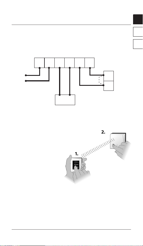
Wiring
Danfoss Link™ DBR
Electronics
Remove
1NL 234
230 V AC
ESM-11
Note: Refer to boiler manufacturer’s manual for wiring connections
to the boiler.
jumper
if tted
T
T
Boiler ON/OFF
terminals
Adding the device
The process of adding the D anfoss Link™ DBR
to a system is performed on the Danfoss
Lin k™ CC.
Note that the Danfoss Link™ DBR
must be added as a Service
Device.
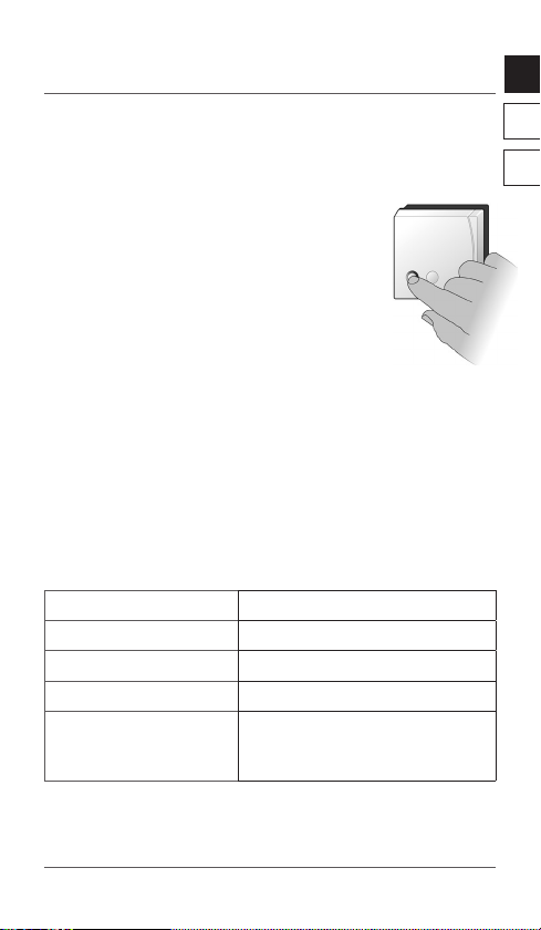
When adding, press and
release the install button,
and observe that the LED
gives a fast green ash.
If adding is successful the LED turns green permanently.
For further information, see the D anfoss Link™ CC instruction
manual.
NL
FR
Note: If adding the D anfoss Link™ DBR to the Danfoss Link™ CC is
unsuccessful, make sure th e right Danfoss Link™ CC software
version is applied. Correct ver sion: 4.1.0 or higher.
VIIOS202 © Danfoss 07/2017
7
Page 8
Installation Guide Danfoss Link™ DBR
UK
NL
Congure Danfoss LinkTM DBR
FR
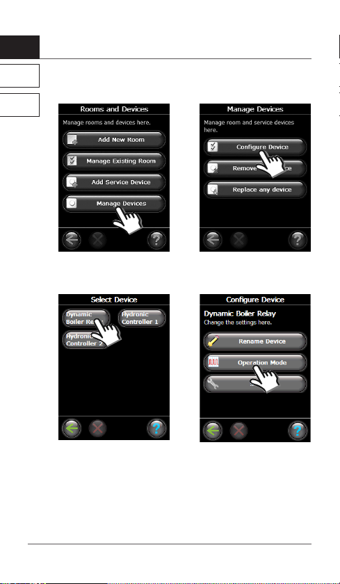
Select “Manage Devices” in
“Rooms and Devices”.
Select Device to congure Select operation mode
8
VIIOS202 © Danfoss 07/2017
Select “Congure Device”.
according to the application
Page 9
UK
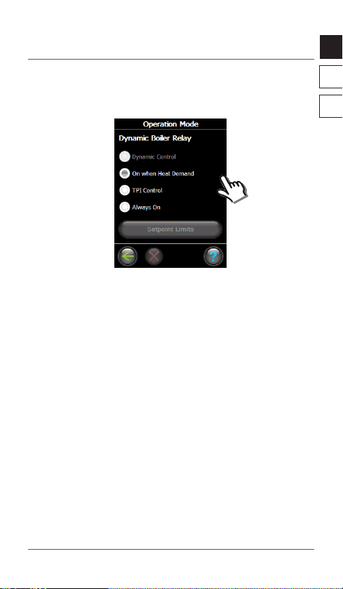
Congure the Danfoss LinkTM DBR Operation
Mode
Dynamic Control (Recommended)
When Dynamic Control is selected, the on/o cycles are determined by the heat demand in the rooms and the temperature
of the return pipe into the boiler to optimize energy savings.
Recommended in systems with bypass in heating circuit, such
as AVDO valve. It is possible to adjust the Setpoint Limits in
this mode. Dynamic Control only possible to select with ESM11 sensor mounted on return pipe
On when Heat Demand
The boiler is only ON when there is heat demand from a
reference room in the system. Recommended for modulating boilers and non-condensing boilers.
TPI (Time Proportional Interval)
A duty cycle is calculated and used to control the boiler.
Select ‘Cycle Time’ in Settings.
NL
FR
VIIOS202 © Danfoss 07/2017
9
Page 10
UK
Installation Guide Danfoss Link™ DBR
NL
Setpoint Limits
FR
The recommended Maximum Temperature is below 54 degrees to
ensure maximum eciency with condensing boilers.
If Maximum Temperature is set too low, there is a risk of not reaching
the desired temperature.
Congure the Minimum
Temperature and Maximum
temperature for Return Line
setpoint temperatures for
Danfoss Link™ DBR here.
(Note: You can only set these
setpoint limits within the
Dynamic mode.)
Congure settings of the Danfoss LinkTM DBR
Relay Output Conguration
NO (Normally Open) and NC (Normally Closed)
Cycle time
• 6 cycles/hour is recommended for condensing non-modulating gas boilers.
• 3 cycles/hour is recommended for condensing non-modulating oil boilers.
10
VIIOS202 © Danfoss 07/2017
Page 11
UK
Perform network test
Once the Danfoss Link™ DBR and all other devices in the system
have been registered and the Danfoss Link™ CC is placed in
its nal position, perform a network test (see
separate Danfoss Link™ CC manual).
Note: If the connection to the Danfoss Link™ CC is
lost for more than 1½ hour, the Danfoss Link™
DBR will go into safety mode. In this mode the
boiler will be turned ON continuously.
Factory reset
Turn o the power to the device, then press and hold the install
button in front of the device for approx. 5 sec. while the power
is switched on again. The button must be held until LED gives a
red ash.
Status indicator
Green LED OFF Relay OFF/Standby
Green LED ON Relay ON/Heating
Green LED fast ash Adding or link test
Green LED short ash Ready for adding
Red LED slow ash Adding not OK
Link test not OK
Safe State Active
NL
FR
VIIOS202 © Danfoss 07/2017
11
Page 12

Installation Guide Danfoss Link™ DBR
UK
NL
Technical specications
FR
Operation voltage 230 V AC, 50 Hz
Standby consumption 1.6 W
Load
Rated impulse voltage 2.5 kV
Switching Type 1B
Regulation ON/OFF
Ambient temperature 0˚ to +45˚C
Transmission frequency Wireless Z-wave 868.42 MHz
Transmission range in
normal buildings
Transmission power Max. 1 mW
Pollution situation Degree 2
Ball pressure test 75˚C
Software classication Class A
Software version 4.1.0 or higher
IP class 40
Dimensions 84 × 84 × 30 mm
3 amps resistive
1 amp inductive
Up to 30 m
Disposal instructions
12
VIIOS202 © Danfoss 07/2017
Page 13

VIIOS202 © Danfoss 07/2017
13
Page 14

Installatiehandleiding Danfoss Link™ DBR
UK
NL
NL
Inhoudsopgave
Inleiding................................................... 15
FR
Installatie ............................................... 15
Installatie in een toepassing met een AVDO-bypassklep ..16
Montage .................................................. 17
Bedrading . . . . . . . . . . . . . . . . . . . . . . . . . . . . . . . . . . . . . . . . . . . . . . . . . 18
Het apparaat toevoegen .................................. 18
Danfoss Link™ DBR congureren ............................. 19
Danfoss Link™ DBR-bedrijfsmodus congureren.............. 20
De instellingen van het Danfoss Link™ DBR congureren ..... 21
Netwerktest uitvoeren .................................... 22
Terugzetten naar fabrieksinstellingen..................... 22
Statusindicator .......................................... 22
Technische specicaties................................... 23
Instructies voor verwijdering.............................. 23
Belangrijke informatie
Om veiligheidsredenen moet het verwarmingssysteem zijn
voorzien van een bypassfunctie. Deze functie is ingebouwd in
de cv-ketel of moet worden geïnstalleerd in het systeem.
Demonteer eventuele andere verwarmingsregelingstimers in de
installatie. Als u dit niet doet, zullen ze het algoritme van de Danfoss
Link™-verwarmingsregeling verstoren. Als er een weersafhankelijke
regeling beschikbaar is, moet u die instellen op constant comfort.
Elektrische verwarmingstoestellen worden niet ondersteund.
14
VIIOS202 © Danfoss 07/2017
Page 15

UK
Inleiding
Het Danfoss Link™ dynamische ketelrelais (DBR) is een elektronisch
component die de gas- en stookolieketels in- en uitschakelt op basis
van de warmtevraag.
Het Danfoss Link™ DBR moet in toepassingen met een
bypassklep, zoals AVDO, worden geïnstalleerd met de
ESM-11-temperatuursensor (opgenomen in de doos) om de
cv-ketel in en uit te schakelen op basis van de warmtevraag en
de watertemperatuur in de retourbuis, om het systeem zo
energie-eciënt mogelijk te laten werken.
Dit pakket bestaat uit:
1 Danfoss Link™ dynamisch ketelrelais
1 ESM-11-temperatuursensor
Installatie
Het transmissiebereik van het draadloze Danfoss Link™-systeem
is groot genoeg voor de meeste toepassingen; elk gebouw kent
echter andere obstakels die de communicatie en de maximale
transmissieafstand kunnen beïnvloeden. Danfoss beveelt aan
om bij communicatieproblemen accessoires te gebruiken om
het systeem te ondersteunen, zoals signaalversterkers, de RU.
In uitzonderlijke gevallen kan het zijn dat het draadloze systeem
niet geschikt is voor uw installatie.
NL
FR
De installatie en plaatsing moeten voldoen aan
de lokale bouwvoorschriften.
VIIOS202 © Danfoss 07/2017
15
Page 16

UK
HR-ketel
Bypassklep
(AVDO)
Dynamisch
ketelrelais
(DBR)
ESM-11
Temperatuursensor
70 °C
70 °C
50 °C
50 °C
HR-ketel
Bypassklep
(AVDO)
Dynamisch
ketelrelais
(DBR)
ESM-11
Temperatuursensor
70 °C
70 °C
50 °C
50 °C
HR-ketel
Dynamisch
ketelrelais (DBR)
70 °C
70 °C
50 °C
50 °C
Bypassklep
(AVDO)
ESM-11
Temperatuursensor
Installatiehandleiding Danfoss Link™ DBR
NL
Installatie in een toepassing met een
AVDO-bypassklep
FR
In installaties met een AVDO-bypassklep moet u niet vergeten
om de bij het pakket geleverde ESM-11-temperatuursensor
te monteren en te bedraden.
Let op:
· De E SM-11-temperatuur sensor moet op de r etourbuis worde n
gemonteerd.
· Mo nteer de ESM-11-temp eratuursensor i n het bypasscircui t
(afbeel ding 1) en niet buiten he t circuit (afbeeld ing 2). Let op!
De sensor n iet op de centrale re tour plaatsen wa nneer er een
indirect gestookte boiler in het systeem zit.
Afbeelding 1
Afbeelding 2
16
VIIOS202 © Danfoss 07/2017
Page 17

UK
NL
Het wordt niet aanbevolen het Danfoss Link™ DBR te gebruiken in
toepassingen zonder bypassklep. Installeer het Danfoss Link™ DBR
in combinatie met, bijvoorbeeld, een AVDO-bypassklep.
Als de cv-ketel is uitgerust met een interne bypassklep en werkt op
basis van een weersafhankelijke regeling, kunt u het Danfoss Link™
DBR zonder retoursensor installeren, in de bedrijfsmodus “Aan
bij warmtevraag”. Bij deze instelling kijkt de regeling niet naar
de retoursensor.
Montage
Let op:
De Danfoss Link ™ DBR moet op een vlakke ondergrond worden
gemonteerd.
Raadpleeg de bijgesloten installatiegids van de ESM-11-temperatuursensor voor de juiste montage van de temperatuursensor op de retour.
FR
VIIOS202 © Danfoss 07/2017
17
Page 18

Installatiehandleiding Danfoss Link™ DBR
UK
NL
Bedrading
FR
Elektronica van het
Danfoss Link™
DBR
1NL 234
Verwijder de
doorverbinding
indien aanwezig.
230 V AC
ESM-11
Let op: Raadpleeg het bedienings- en installatievoorschrift van de
ketelfabrikant voor de bedradingsaansluitingen naar de ketel.
T
T
Aan-uitklemmen
van ketel
(kamerthermo-
staataansluiting)
Het apparaat toevoegen
Het toevoegen van het Danfoss Link™ DBR aan
het systeem gebeurt via de D anfoss Link™ CC.
Het Danfoss Link™ DBR moet
worden toegevoegd als een
Servicecomponent.
Tijdens het toevoegen
moet de installatieknop
kort ingedrukt worden; kijk
gelijktijdig of de groene led
snel gaat knipperen.
Als het toevoegen geslaagd
is, brandt de groene led
permanent.
Zie de instructiehandleiding van de Danfoss Link™ CC voor meer
informatie.
Let op: Als het niet gel ukt is om het Danfoss Link™ DBR a an de Danfoss
Link™ CC toe te voegen, mo et u controleren of de correc te softwareversie van d e Danfoss Link™ CC gebruikt is. Res et eventueel
de DBR en prob eer het opnieuw. Correcte ve rsie: 4.1.0 of hoge r.
18
VIIOS202 © Danfoss 07/2017
Page 19

UK
Danfoss Link™ DBR congureren
Selecteer “Componenten beheren” in “Ruimtes en apparaten”.
Selecteer de component
die u wilt congureren.
Selecteer “Component
congureren”.
Selecteer de bedrijfsmodus
op basis van de toepassing.
NL
FR
VIIOS202 © Danfoss 07/2017
19
Page 20

UK
Installatiehandleiding Danfoss Link™ DBR
NL
Danfoss Link™ DBR-bedrijfsmodus
congureren
FR
Dynamische regeling (aanbevolen)
Wanneer Dynamische regeling is geselecteerd, worden de
aan/uit-cycli bepaald door de warmtevraag in de ruimtes en
de temperatuur van de retour naar de cv-ketel, zodat optimale
energiebesparingen kunnen worden behaald.
Aanbevolen in systemen met een bypass zoals de AVDO-klep.
In deze modus kunt u de setpointlimieten, max. en min. retourtemperatuur aanpassen. Dynamische regeling kan alleen
geselecteerd worden als de ESM-11 sensor gemonteerd is op de
retourleiding.
Aan bij warmtevraag
De ketel staat alleen aan wanneer een referentieruimte in het
systeem warmte vraagt. Aanbevolen voor niet-condenserende
ketels.
TPI (tijdklokinterval)
Om de ketel te sturen wordt een werkcyclus berekend en gebruikt.
Selecteer “Cyclustijd” in Instellingen.
20
VIIOS202 © Danfoss 07/2017
Page 21

UK
Setpointlimieten
Hier congureert u de
minimale en de maximale
setpointtemperatuur voor
de retour.
(Let op: u kunt deze setpointlimieten alleen in de Dynamische
modus instellen.)
De aanbevolen maximumtemperatuur bedraagt minder dan 54 graden
met het oog op maximale eciëntie van condenserende ketels.
Wanneer een te lage maximumtemperatuur wordt ingesteld, bestaat
het risico dat de ketel de gewenste temperatuur niet bereikt.
De instellingen van het Danfoss Link™ DBR
congureren
Relaisuitgang conguratie
NO (normaal open) en NC (normaal gesloten)
Cyclustijd
• 6 cycli per uur worden aanbevolen voor condenserende
niet-modulerende gasgestookte cv-ketels.
• 3 cycli per uur worden aanbevolen voor condenserende
niet-modulerende oliegestookte cv-ketels. En trage systemen
met bijvoorbeeld vloerverwarming als hoofdverwarming.
NL
FR
VIIOS202 © Danfoss 07/2017
21
Page 22

Installatiehandleiding Danfoss Link™ DBR
UK
NL
Netwerktest uitvoeren
Zodra het Danfoss Link™ DBR en alle andere
FR
systeemcomponenten zijn geregistreerd en
de Danfoss Link™ CC op de uiteindelijke locatie
gemonteerd is, voert u een netwerktest uit
(zie de afzonderlijke handleiding van de
Danfoss Link™ CC).
Let op: Als de verbinding met de Danfoss Link™ CC
langer dan 1,5 uur verbroken is, zal het
Danfoss Link™ DBR naar de veiligheidsmodus gaan. In deze modus zal de ketel continu AAN staan,
begrensd op zijn maximaal ingestelde retourtemperatuur.
Terugzetten naar fabrieksinstellingen
Schakel de stroom naar de component uit, houd de installatieknop
aan de voorzijde van het toestel ingedrukt en schakel de stroom weer
in; laat de knop niet los! De knop moet ingedrukt gehouden worden
tot de rode led knippert.
Statusindicator
Groene led UIT Relais uit/stand-by
Groene led AAN Relais aan/verwarming
Groene led knippert snel Toevoegen of verbindingstest
Groene led knippert kort Klaar om toe te voegen
Rode led knippert
langzaam
Toevoegen niet gelukt
Verbindingstest niet geslaagd
Veiligheidsstatus actief
22
VIIOS202 © Danfoss 07/2017
Page 23

UK
NL
Bedrijfsspanning 230 V AC, 50 Hz
Verbruik in stand-by 1,6 W
Belasting
Nominale impulsspanning 2,5 kV
Schakeling Type 1B
Regeling AAN/UIT
Omgevingstemperatuur 0 tot +45 °C
Transmissiefrequentie Draadloze Z-wave 868,42 MHz
Transmissiebereik in
normale gebouwen
Transmissievermogen Max. 1 mW
Verontreinigingsgraad Niveau 2
Druktest kogel 75 °C
Softwareclassicatie Klasse A
Software Versie 4.1.0 of hoger
Beschermingsgraad IP 40
Afmetingen 84 × 84 × 30 mm
3 A resistief
1 A inductief
Tot 30 m
Instructies voor verwijdering
FR
VIIOS202 © Danfoss 07/2017
23
Page 24

Manuel d’installation Danfoss Link™ DBR
UK
NL
Sommaire
Introduction................................................. 25
FR
Installation .................................................. 25
Installation dans une application avec une vanne
de bipasse AVDO ............................................ 26
Montage . . . . . . . . . . . . . . . . . . . . . . . . . . . . . . . . . . . . . . . . . . . . . . . . . . . . 27
Câblage ..................................................... 28
Ajout de l’appareil........................................... 28
Conguration du Danfoss Link™ DBR ........................... 29
Conguration du mode de fonctionnement DBR ............. 30
Conguration des réglages DBR.............................. 29
Test du réseau............................................... 32
Restauration des réglages par défaut......................... 32
Indicateur d’état............................................. 32
Caractéristiques techniques.................................. 33
Instructions pour la mise au rebut............................ 33
Informations importantes
Pour des raisons de sécurité, le système de chauage doit disposer
d’une vanne de décharge. Elle doit être intégrée à la chaudière ou
installée dans le système.
Démontez les autres programmateurs de commande du chauage
présents dans l’installation car ils risquent de créer des interférences
avec l’algorithme de commande du chauage Danfoss Link™.
Si un régulateur en fonction de la température extérieureest
installé, il doit être réglé sur confort constant.
Les dispositifs de chauage électriques ne sont pas pris en charge.
24
VIIOS202 © Danfoss 07/2017
Page 25

Manuel d’installation Danfoss Link™ DBR
UK
Introduction
Le Danfoss Link™ DBR (relais de chaudière dynamique) est un électronique appareil servant à allumer et à éteindre les chaudières à gaz
ou à oul, en fonction de la demande de chauage.
Le Danfoss Link™ DBR doit être installé dans des applications avec
vanne de bipasse telle que AVDO, en combinaison avec la sonde de
température ESM-11 (inclus dans la boîte) an d’allumer et éteindre
la chaudière en fonction de la demande de chauage et de la température d’eau dans la conduite de retour an d’optimiser l’ecacité
énergétique du système.
Ce pack comprend:
1 x relais de chaudière dynamique Danfoss Li nk™,
1 x sonde de température ESM-11.
Installation
La portée d’émission du système sans l Danfoss Link™ est susante
pour la plupart des applications. Chaque bâtiment présente
néanmoins des obstacles diérents qui aectent la communication
et la distance maximale de transmission. En cas de problèmes de
communication, Danfoss recommande d’installer des accessoires
pour assister le système, par exemple des répéteurs.
Dans des cas exceptionnels, le système sans l peut ne pas convenir
à votre installation.
NL
FR
N’oubliez pas que l’installation et le choix de l’emplacement
doivent respecter les réglementations locales relatives à la
construction.
VIIOS202 © Danfoss 07/2017
25
Page 26

Manuel d’installation Danfoss Link™ DBR
Chaudière à
condensation
Vanne de
bipasse
(AVDO)
Relais de chaudière
dynamique (DBR)
ESM-11
Sonde de température
70°C
70°C
50°C
50°C
Chaudière à
condensation
Vanne de
bipasse
(AVDO)
Relais de chaudière
dynamique (DBR)
ESM-11
Sonde de température
70°C
70°C
50°C
50°C
Chaudière à
condensation
Relais de chaudière
dynamique (DBR)
70°C
70°C
50°C
50°C
Vanne de
bipasse
(AVDO)
ESM-11
Sonde de température
UK
NL
Installation dans une application avec
une vanne de bipasse AVDO
FR
Pour les installations avec bipasse AVDO, n’oubliez pas de monter et
de raccorder la sonde de température ESM-11 incluse dans le pack.
Remarque :
· La so nde de températu re ESM-11 doit être mo ntée sur la conduite
de retour.
· Mo ntez la sonde de temp érature ESM-11 dans le circuit de bi passe
(gure 1) et non en d ehors du circuit (gu re 2). Faites attentio n que
ESM-11 doit être à l’exté rieur du circuit d ’un éventuel réser voir de
stockage.
Figure 1
Figure 2
26
VIIOS202 © Danfoss 07/2017
Page 27

Manuel d’installation Danfoss Link™ DBR
UK
NL
Le Danfoss Link™ DBR n’est pas conseillé dans une application
sans vanne de bipasse. Installez le Danfoss Link™ DBR avec par
ex. une vanne de bipasse AVDO.
Si la chaudière possède une vanne de bipasse interne et une
régulation en fonction de l’extérieur, le Danfoss Link™ DBR peut
être installé sans sonde de retour, en mode de fonctionnement
«Activé si demande de chauage».
Montage
Remarque :
Le Danfoss Link ™ DBR doit être monté sur une surface plane.
Veuillez consulter le guide d’installation pour sonde de
température ESM-11 en annexe an de monter la sonde
de température correctement.
FR
VIIOS202 © Danfoss 07/2017
27
Page 28

Manuel d’installation Danfoss Link™ DBR
UK
NL
Câblage
FR
Électronique
Danfoss Link™
DBR
1NL 234
Enlevez le
cavalier s’il
est installé
230 V AC
ESM-11
Remarque : reportez-vous au manuel du fabricant de la chaudière pour
les raccordements à la chaudière.
T
T
Bornes ON/OFF
de la chaudière
Ajout de l’appareil
L’ajout du D anfoss Link™ DBR à un système
s’eectue depuis le Da nfoss Link™ CC.
Notez que le D anfoss Link™ DBR doit
être ajouté en tant qu’appareil de
service.
Lors de l’ajout, appuyez sur
le bouton d’installation, puis
relâchez-le. Vériez que le
voyant émet un clignotement
vert rapide.
Si l’ajout est réussi, le voyant
reste vert en continu.
Pour de plus amples informations, consultez le mode d’emploi
du Danfoss Link™ CC .
Remarque: si l’ajout du D anfoss Link™ DBR sur le Danfoss Link™ CC
28
échoue, véri ez que la version du logi ciel du Danfoss
Link™ CC appliquée e st correcte. Version correcte :
4.1.0 ou supérieure.
VIIOS202 © Danfoss 07/2017
Page 29

Manuel d’installation Danfoss Link™ DBR
UK
Conguration du Danfoss Link™ DBR
Sélectionnez Gérer les unités
locales dans Pièces et unités
locales.
Sélectionnez le dispositif à
congurer.
Sélectionnez Congurer l’unité.
Sélectionnez le mode
de fonctionnement selon
l’application.
NL
FR
VIIOS202 © Danfoss 07/2017
29
Page 30

Manuel d’installation Danfoss Link™ DBR
UK
NL
Conguration du mode de fonctionnement
du Danfoss LinkTM DBR
FR
Contrôle dynamique (conseillé)
Lorsque le contrôle dynamique est sélectionné, les cycles allumés/
éteints sont déterminés par la demande de chaleur dans les pièces
et par la température de la conduite de retour dans la chaudière
an d’optimiser les économies d’énergie.
Recommandé pour les systèmes avec bipasse dans le circuit de
chauage tel que la vanne AVDO. Il est possible d’ajuster les
limites de la température de consigne dans ce mode. Le contrôle
dynamique n’est possible que si une sonde ESM-11 est montée sur
la conduite retour
Activé si demande de chauage
La chaudière n’est en marche que lorsqu’une pièce de référence
du système émet une demande de chaleur. Cette conguration
est recommandée pour les chaudières à marche modulée et les
chaudières sans condensation.
TPI (période du mode chrono-proportionnel)
Un cycle d’utilisation est calculé et sert à commander la chaudière.
Sélectionnez Durée du cycle dans Réglages.
30
VIIOS202 © Danfoss 07/2017
Page 31

Manuel d’installation Danfoss Link™ DBR
UK
Limites de la température de
consigne
Congurez ici la température
minimum et maximum des
températures de consigne de
la conduite de retour pour le
Danfoss Link™ DBR.
(Remarque: vous pouvez
uniquement régler ces limites
de température de consigne en
mode dynamique.)
La température maximale recommandée se situe sous les 54 degrés an
de garantir une ecacité maximale des chaudières à condensation.
Si la température maximale dénie est trop basse, la température
désirée pourrait ne pas être atteinte.
Conguration des réglages
du Danfoss LinkTM DBR
Conguration du relais de sortie
NO (normalement ouverte) et NF (normalement fermée)
Durée du cycle
• 6 cycles/heure sont recommandés pour les chaudières à gaz,
à condensation et à marche non modulée.
• 3 cycles/heure sont recommandés pour les chaudières à oul,
à condensation et à marche non modulée.
VIIOS202 © Danfoss 07/2017
NL
FR
31
Page 32

Manuel d’installation Danfoss Link™ DBR
UK
NL
Test du réseau
Une fois le Danfoss Link™ DBR et tous les autres
FR
appareils du système enregistrés et lorsque le
Danfoss Link™ CC est à son emplacement nal,
testez le réseau (voir le manuel Danfoss Link™ CC
spécique).
Remarque: si la connexion au Danfoss Link™ CC
est perdue pendant plus d’une heure
et demie, le Danfoss Link™ DBR passe
en mode de sécurité. Sous ce mode,
la chaudière reste activée en continu.
Restauration des réglages par défaut
Coupez l’alimentation du dispositif, puis appuyez sur le bouton
d’installation à l’avant du dispositif pendant 5 secondes environ
tandis que l’alimentation est rétablie. Le bouton doit rester
enfoncé jusqu’à ce que le voyant émette un clignotement rouge.
Indicateur d’état
Voyant vert éteint Relais désactivé/Veille
Voyant vert en continu Relais activé/Chauage
Clignotement vert rapide Ajout ou test de liaison
Clignotement vert court Prêt pour l’ajout
Clignotement rouge lent Ajout non eectué
Test de liaison non eectué
Mode de sécurité activé
32
VIIOS202 © Danfoss 07/2017
Page 33

Manuel d’installation Danfoss Link™ DBR
UK
Caractéristiques techniques
Tension de fonctionnement 230 V CA, 50 Hz
Consommation en veille 1,6W
Charge
Tension d’impulsions
nominale
Commutation Type 1B
Régulation ON/OFF
Température ambiante 0˚ à +45˚C
Fréquence de transmission Z-Wave sans l 868,42 MHz
Portée d’émission dans des
bâtiments normaux
Puissance de transmission 1 mW max.
Degré de pollution Degré 2
Essai à la bille 75˚C
Classe du logiciel Classe A
Version Software
Classe IP 40
Dimensions 84 × 84 × 30 mm
résistive : 3 A
inductive :1 A
2,5 kV
Jusqu’à 30m
4.1.0 ou supérieure
Instructions pour la mise au rebut
NL
FR
VIIOS202 © Danfoss 07/2017
33
Page 34

Installation Guide Danfoss Link™ DBR
34
VIIOS202 © Danfoss 07/2017
Page 35

VIIOS202 © Danfoss 07/2017
35
Page 36

Danfoss A/S
Heating Solutions
Haarupvaenget 11
8600 Silkeborg
Denmark
Email: heating.solutions@danfoss.com
www.heating.danfoss.com
013R9624 VII OS202 © Danfoss 07/2017
 Loading...