

Installation Guide
Danfoss Link™ CC Central Controller
www.danfoss.com
Installation Guide Danfoss Link™ CC
Danfoss Heating Solutions VISGL902N 01/2019
2
Installation Guide Danfoss Link™ CC
Installation Guide.................................................. 5
Guida all’installazione ...........................................39
Asennusohje .....................................................73
Montavimo vadovas .............................................107
Uzstādīšanas rokasgrāmata......................................141
Paigaldusjuhend ................................................175
Instalační příručka...............................................209
Instrukcja montażu..............................................243
Інструкція з монтажу............................................277
Danfoss Heating Solutions VISGL902N 01/2019
GB
IT
FI
LT
LV
EE
CZ
PL
UA

Installation Guide Danfoss Link™ CC
01/2019 VISGL902N Danfoss Heating Solutions
4
Installation Guide Danfoss Link™ CC
Content
1. Quick guide for installation ........................................ 7
2. Introduction ...................................................... 8
3. Guidelines for installation ......................................... 9
3.1. Correct installation plan............................................10
3.2. Incorrect installation plan ..........................................11
3.3. How and when to use repeater units ...............................12
3.4. Where to place repeater units ......................................13
4. Installation....................................................... 15
4.1. Adding devices to the system ......................................16
4.2. Connecting power,setting country, language and date/time........16
4.3. Starting up the installation menu ..................................17
4.4. Mounting Mains powered devices..................................17
4.5. Adding service devices.............................................18
4.6. Mounting battery operated devices ................................19
4.7. Creating rooms ....................................................19
4.8. Adding room devices ..............................................20
4.9. Performing a network test .........................................21
4.10. Finalizing installation ..............................................22
Danfoss Heating Solutions VISGL902N 01/2019
GB
GB
5

Installation Guide Danfoss Link™ CC
5. Modifying an existing installation................................. 23
5.1. Adding devices to an existing room ................................23
5.2. Changing parameters for Heat Regulations .........................24
5.3. Removing a room or service device from the network ..............26
5.4. Factory reset of Danfoss Link™ CC ..................................28
6. Wi-Fi and App connection.........................................29
6.1. Connect to Wi-Fi ...................................................29
6.2. Connect to App....................................................30
6.3. Edit connected devices ............................................31
7. Upgrading software version ......................................32
8. Warnings.........................................................33
8.1. Alert icons . . . . . . . . . . . . . . . . . . . . . . . . . . . . . . . . . . . . . . . . . . . . . . . . . . . . . . . . .34
9. Technical specications and approvals ............................ 35
10. Disposal instruc tions .............................................38
01/2019 VISGL902N Danfoss Heating Solutions
6
Installation Guide Danfoss Link™ CC
K”
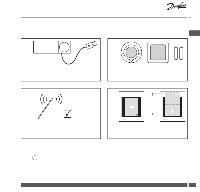
1. Quick guide for installation
1. 2.
^
^
Install all mains powered devices
rst, and add to network.
3.
“O
Perform the network test with the
Danfoss Link™ CC in its nal position.
Create rooms and add battery operated devices one by one.
4.
Unfold
Manual
Updates
Information
and
place
www.link.danfoss.com
Place the hanger onto the Danfoss
Link™ CC.
Tips!
• The ? key can be used at any point during installation.
• Always look for the latest software version at www.link.danfoss.com before installation. See chapter 7: Upgrading sof tware version.
Danfoss Heating Solutions VISGL902N 01/2019
Welcome
Wilkommen
Velkommen
Välkommen
Powitanie
Bienvenue
Information
Manual
Updates
www.link.danfoss.com
+-+
Welkom
Bienvenido
Vitán
Teretulnud
Gaidīts
Tervetuloa
GB
GB
-
7
Installation Guide Danfoss Link™ CC
!
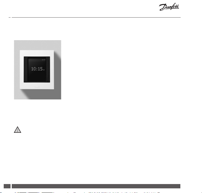
2. Introduction
Danfoss Link™ is a programmable, wireless control
system for heating systems in residential buildings (up
to approximately 300 m2).
The central controlling unit is the Danfoss Link™ CC
equipped with a colour touch screen, from which the
entire installation can be controlled.
This installation guide contains all information about
the Danfoss Link™ CC and how to get started. It guides
through recommendations and considerations that
must be taken into account when handling a wireless
system - and it describes conguration of the system,
to ensure a smooth and reliable system set-up.
Individual instructions, supplied with the service and room devices, contain
information about connecting the respective device to the network. The instruction will also state if the device is considered a service or a room device.
01/2019 VISGL902N Danfoss Heating Solutions
8

Installation Guide Danfoss Link™ CC
3. Guidelines for installation
The signal strength is sucient for most applications, however, wireless signals
are weakened on the way from the Danfoss Link™ CC to the room devices and
each building has dierent obstacles.
Ensure the best performance by keeping the following in mind for planning and
installation:
• Max. 30 m between devices in free space.
• Receiving devices should be placed on opposite or next wall as the transmitter,
if possible.
• All metallic parts in the building construction can weaken wireless signals.
• Reinforced concrete walls and oors weaken the signal strength signicantly,
but almost all types of construction materials reduce the signal to some
degree.
• Corners, which is a result of the design of the building, can weaken the wireless
signals, due to either a longer distance or missing reecting opportunities.
Note!
To get a good overview of the devices in each rooms, and their placement, Danfoss
recommends that an installation plan is made before beginning the actual installation.
Danfoss Heating Solutions VISGL902N 01/2019
GB
GB
9
Installation Guide Danfoss Link™ CC
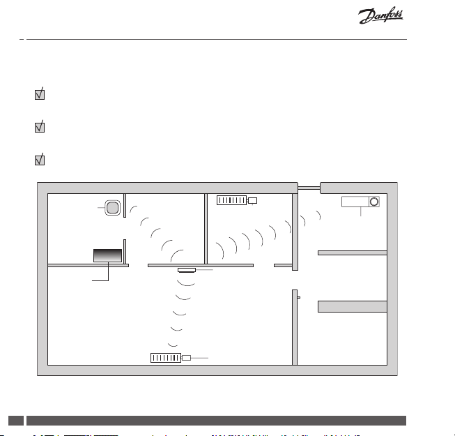
3.1. Correct installation plan
No metal objects between the Danfoss Link™ CC and other wireless Danfoss
units.
The Danfoss Link™ CC is installed as central as possible on the oor plan
(max. 30 m between devices in free space).
Wireless signal through walls on shortest possible diagonal distance.
Danfoss
Icon™ RT
(room device)
Metal
object
01/2019 VISGL902N Danfoss Heating Solutions
10
living connect®
(room device)
Danfoss Link™ CC
living connect®
(room device)
Danfoss
Link™ HC
(service device)
Installation Guide Danfoss Link™ CC
!
!
!
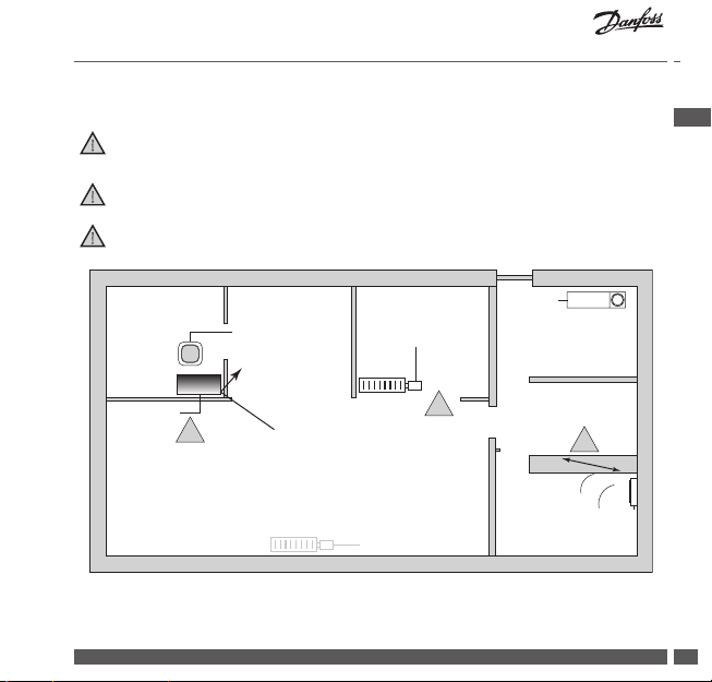
3.2. Incorrect installation plan
Metal objects between the Danfoss Link™ CC and other wireless Danfoss
units.
Decentral installation of the Danfoss Link™ CC.
Crossing walls diagonally.
Danfoss
Link™ HC
Danfoss Icon™ RT
(room device)
living connect®
(room device)
(service device)
GB
Metal
object
!
living connect®
(room device)
Danfoss Heating Solutions VISGL902N 01/2019
!
!
Danfoss Link™ CC
11
Installation Guide Danfoss Link™ CC
3.3. How and when to use repeater units
What is the purpose of a repeater unit?
A repeater unit strengthens the wireless signal, when a satisfying connection can
not be etablished between the Danfoss Link™ CC and other wireless Danfoss units.
When is a repeater unit needed ?
1. Complete the installation and perform a network test (see 4.9). If one or more
devices fail, include a repeater unit (CF-RU) in the network, between the
Danfoss Link™ CC and the device(s) that fail.
2. Alternatively, plan ahead. If “yes” is answered to one or more of the following
questions, Danfoss recommends to include a repeater unit at the beginning of
the installation (see 3.4):
• Is internal walls or deck construction between oors made of steel reinforced concrete?
• Is the distance between Danfoss Link™ CC and last device more than 20 m
and signal must pass more than two heavy walls (stone or non-reinforced
concrete)?
• Is the distance between Danfoss Link™ CC and last device more than 25 m
and signal must pass more than 2 light walls (gipsum/wood)?
• Is the distance more than 30m in free line of sight?
A repeater unit (CF-RU) can be ordered on Danfoss code no. 088U0230.
Note!
These are guidelines only, as many factors have inuence on wireless communication.
01/2019 VISGL902N Danfoss Heating Solutions
12
Installation Guide Danfoss Link™ CC
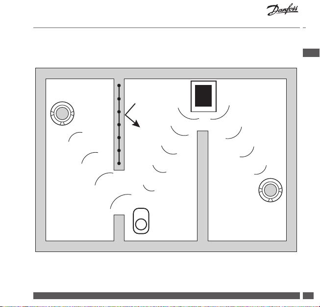
3.4. Where to place repeater units
Plan view, single oor building
Concrete wall,
steel reinforced
^
^
21
Signal
blocked
Strong signal
Repeater
unit
Danfoss Link™ CC
Strong signal
^
GB
^
21
Danfoss Heating Solutions VISGL902N 01/2019
13
Installation Guide Danfoss Link™ CC
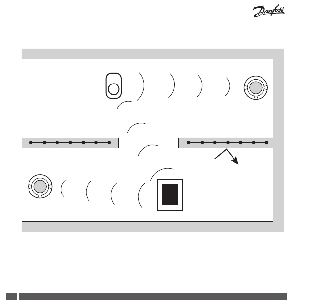
Cross section view - building with more than one oor
1st oor
Repeater unit
Strong signal
Ground level
^
Strong signal
^
21
Signal blocked
Danfoss Link™ CC
01/2019 VISGL902N Danfoss Heating Solutions
14
^
^
21
Installation Guide Danfoss Link™ CC
!
4. Installation
Danfoss Link™ CC can be installed
with either a PSU (in-wall power
supply) or a NSU (net power supply).
Installing Danfoss Link™ CC with In-Wall PSU
• Hold the PSU over the wall box and mark up the 4 screw holes.
Make sure the top is level.
• Drill holes and put tting plugs in.
• Connect the PSU according to the connection diagram on the
back side.
• Mount the PSU with the 4 screws.
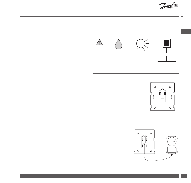
Installing Danfoss Link™ CC with NSU
• Hold the mounting plate on the wall and mark up the 4
screw holes. Make sure the top is level.
• Drill holes and put tting plugs in.
• Mount the mounting plate with the 4 screws. Do not
mount the Danfoss Link™ CC yet!
• Connect the NSU to a power outlet.
Danfoss Heating Solutions VISGL902N 01/2019
Do not
install in
bathrooms
Avoid direct
sunlight
UP
GB
140-170 cm
Installation
height
UP
PSU
NSU
15
Installation Guide Danfoss Link™ CC
Select Language
Select Country
Set Date and Time
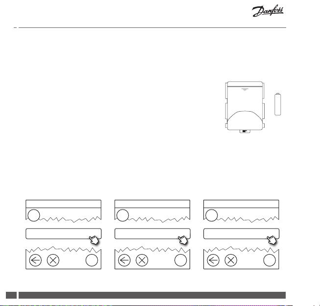
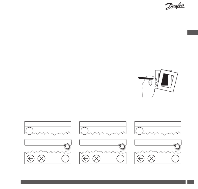
4.1. Adding devices to the system
When adding devices to the Danfoss Link™ system, the distance between the
Danfoss Link™ CC and the device must not exceed 1.5m. To accomplish this
Danfoss Link™ Battery Supply Unit (BSU) is oered as an installation tool.
1. Slide o the lid and add batteries.
2. Slide the lid back on and attach the Danfoss Link™ BSU
battery pack onto the back of the Danfoss Link™ CC. When
x 10
ready to do the commissioning, turn the switch located on
the Danfoss Link™ BSU to the ON position.
Danfoss Link™ CC will now start up. This takes approximately
30 seconds.
01
BSU
A battery pack (BSU) can be ordered on Danfoss code no. 014G0262.
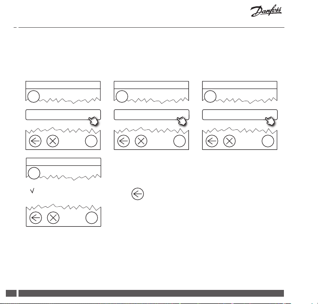
4.2. Connecting power, setting country, language and date/time
1.5 V
+
-
AA
1
Scroll down to select
?
01/2019 VISGL902N Danfoss Heating Solutions
16
2
Scroll down to select
3
Set Date and Time
?
?
Installation Guide Danfoss Link™ CC
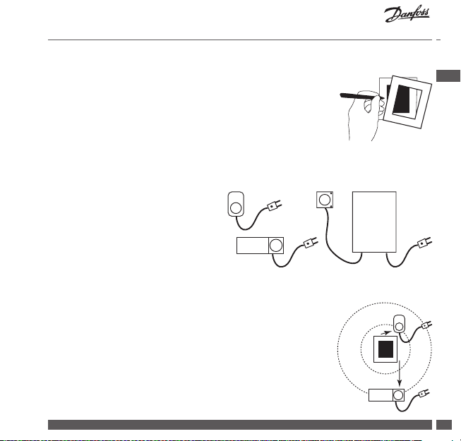
4.3. Starting up the installation menu
• Remove the front cover of the Danfoss Link™ CC by gently
pulling it o, pull near the edges of the cover.
• Press the SETUP pin for 3 seconds to enter the service
area.
4.4. Mounting mains powered devices
Power-up all mains powered
devices rst, and any repeater units
that might be needed.
Note! If Danfoss Link™ HC is used, connect all actuators ( TWA), before mains power-
ing the unit.ON/OFF relays are only visible in the end-user menu.
• Pair devices to Danfoss Link™ CC.
• Start with the device closest to the Danfoss Link™ CC,
and move outwards.
GB
Danfoss Heating Solutions VISGL902N 01/2019
17
Installation Guide Danfoss Link™ CC
!
Service Options
Rooms and Devices
Add Service Device
Edit Device Name
4.5. Adding service devices
Always add dedicated repeater units rst!
Danfoss Link™ CC supports many dierent types of service devices which functions as both simple ON/OFF devices for other electrically equipment, repeater
units and controllers for hydronic systems, and other sub-systems.
1
Rooms and Devices
?
2
Add Service Device
3
Begin Registration
?
4
Enter/Edit Device Name
?
01/2019 VISGL902N Danfoss Heating Solutions
18
?
Installation Guide Danfoss Link™ CC
^
Service Options
Rooms and Devices
Edit Device Name
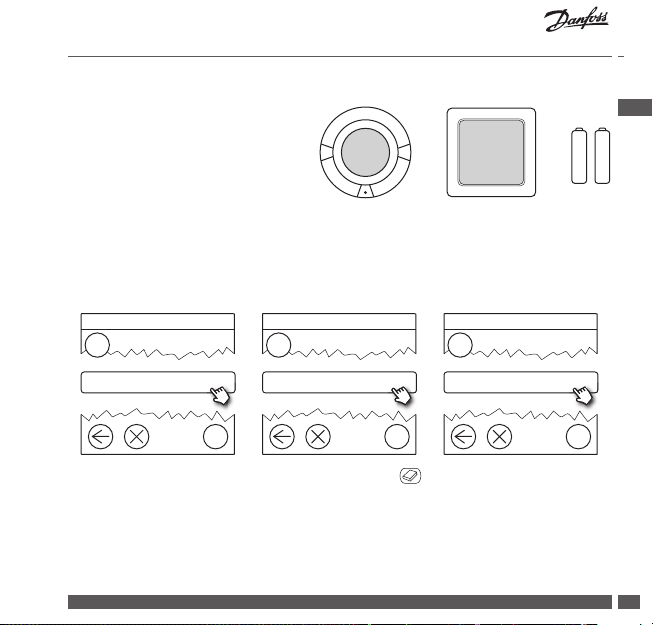
4.6. Mounting battery operated room devices
Create rooms and
operated room devices to the assigned rooms. This can be done in
any order.
add the battery
^
+-+
4.7. Creating rooms
Danfoss recommends to create and add device(s) to one room in a single step,
and thereafter move on to the next room.
GB
-
1
Rooms and Devices
2
?
Tip! A list of common room names is available here
Danfoss Heating Solutions VISGL902N 01/2019
Add New Room
3
Enter/Edit Room Name
?
ABC
.
?
19
Installation Guide Danfoss Link™ CC
Congure Room
Room Devices
Add Room Device
Room Devices
4.8. Adding room devices
A room device regulates temperature in the room where it is installed. All room
devices must be congured, according to the previous installation plan, to
ensure the signal path.
1
Room Devices
?
4
The conguration is valid
2
Press
3
Add a Device
Begin Registration
?
Note!
Danfoss Link™ CC automatically selects
the regulation principle according to the
types of devices in the room. To change
regulation principle, see 5.2 Changing
?
01/2019 VISGL902N Danfoss Heating Solutions
20
parameters for Heat Regulations.
?
Installation Guide Danfoss Link™ CC
Service Options
Status and Diagnostics
Wireless Network Status
4.9. Performing a network test
After nishing installation, perform a network test, to ensure that communication between all added devices and the Danfoss Link™ CC is stable.
Note! Do not perform the net work test before the Danfoss Link™ CC is mounted in
its nal position and ensure that all living connects® are out of mounting mode, see
instructions following the living connect®.
1. Turn o the battery pack.
2. Slide the Danfoss Link™ CC onto the previously
installed mounting plate.
3. The Danfoss Link™ CC will now power-up.
4. Remove the front cover and press the SETUP pin
for 3 seconds to enter the service area.
If there is uncertainty about the network performance, it is recommended to
perform a network test before the installation is completed entirely.
GB
1
Status and Diagnostics
Danfoss Heating Solutions VISGL902N 01/2019
2
Network
?
?
3
Start Network Test
?
21
Installation Guide Danfoss Link™ CC
At the end of the network test the Danfoss Link™ CC awaits for all battery operated
devices to wake up and report. Follow the instructions given on the screen. If the
network test is running smoothly, there will be no need for further interaction. If
the network test is performing slow, the Danfoss Link™ CC guides through trouble
shooting and gives useful tips for speeding up the process.
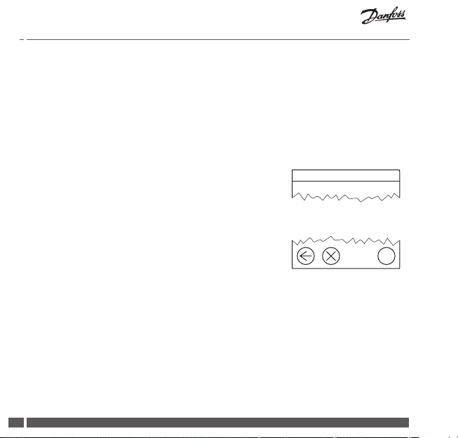
4.10. Finalising installation
Press the SETUP pin to close the installation.
10:15
01/2019 VISGL902N Danfoss Heating Solutions
22
?
Installation Guide Danfoss Link™ CC
Service Options
Rooms and Devices
Manage Existing Rooms
Congure Room
Room Devices
Add Room Device
!
5. Modifying an existing installation
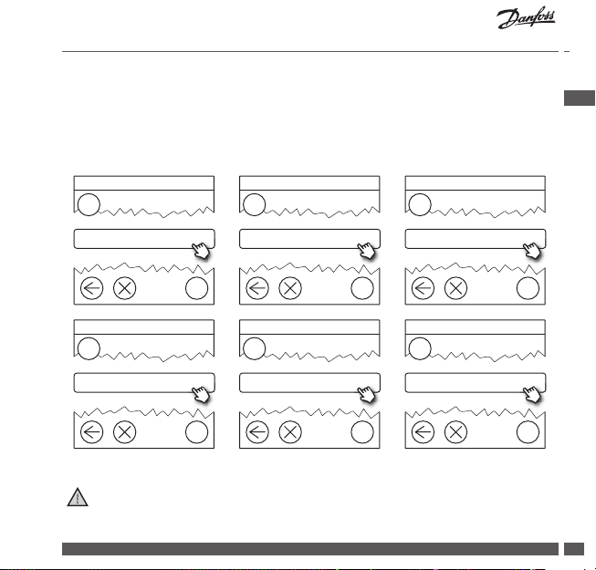
5.1. Adding devices to an existing room
Remove the front cover and press the SETUP pin for 3 seconds to enter the
service area.
1
Rooms and Devices
?
4
Room Devices
Continue until all new devices are added to the desired room.
Perform a network test after modifying the installation.
Danfoss Heating Solutions VISGL902N 01/2019
?
2
Manage Existing Rooms
?
5
Add a device
?
GB
3
Congure Existing Rooms
?
6
Begin Registration
?
23
Installation Guide Danfoss Link™ CC
Service Options
Rooms and Devices
Manage Existing Rooms
Congure Room
Heating Regulation
5.2. Changing parameters for Heat Regulations
Remove the front cover and press the SETUP pin for 3 seconds to enter the
service area.
1
Rooms and Devices
?
4
Heating Regulation
?
2
Manage Existing Rooms
5
Choose a Setting
3
Select a Room
?
?
• Forecasting method: by activation of the forecast method, the system will
automatically predict the heating start-up time necessary to reach the desired
room temperature at desired time (all heat emitter types).
• Maximum oor temperature: the default setting is 35 °C (electrical oor
heating).
• Regulation type: only in connection with electrical heating systems.
01/2019 VISGL902N Danfoss Heating Solutions
24
?

Installation Guide Danfoss Link™ CC
Note! Use pincode [0044] to change between the following regulation types:
Room sensor (regulates only by room temperature) - if only Danfoss Icon™ RT is
tted (hydronic oor heating) or Danfoss Icon™ RT + Danfoss Link™ FT (electrical
heating).
Floor sensor (regulates only by oor temperature ) - if only Danfoss Link™ FT/S
is tted.
Combined room/oor (ensures min. oor temperature and regulates room
temperature in parallel) - Danfoss Icon™ RT + Danfoss Link™ FT/S is tted.
In case of hydronic oor heating, be aware if a certain max. oor temperature is
given by the oor manufacturer. This can be assured by tting a thermostatically
controlled mixing shunt.
GB
Danfoss Heating Solutions VISGL902N 01/2019
25

Installation Guide Danfoss Link™ CC
^
e
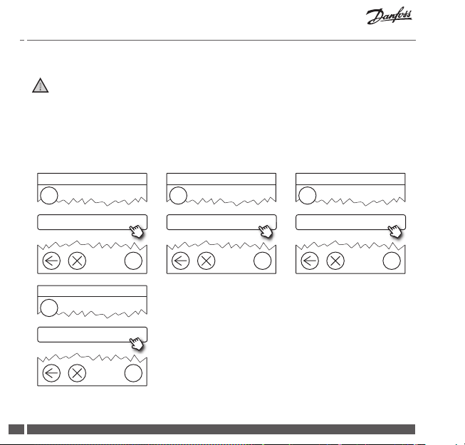
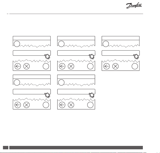
5.3. Removing a room or service device from the network
Devices can be removed from the network by pressing and holding a button
while switching the power on/o (see illustrations). Press the button for approx.
5 seconds after reconnecting the power.
^
living connect® Danfoss Link™ PR CF-RU
Danfoss Icon™ RT Danfoss Link™ HC Danfoss Link™ BR
TOP
N
NL
Danfoss Link™ HR Danfoss CCM/DCM/DLG Danfoss Link™ FT/S
01/2019 VISGL902N Danfoss Heating Solutions
26
1
2
1. Remove devic
2. Power o
Installation Guide Danfoss Link™ CC
Service Options
Rooms and Devices
Manage Devices
Remove Devices
Back-up method for removing a defective or missing device (only if/when
previous method is not possible): Remove the front cover and press the SETUP
pin for 3 seconds to enter the service area.
GB
1
Rooms and Devices
?
2
Manage Devices
3
Remove Any Device
?
4
Delete Dead Device
?
To replace a device, while retaining all settings for that device, use the function
Replace any device and follow the instructions given on the screen. By using
this function, all settings for that particular device, are transferred to the new
unit.
Danfoss Heating Solutions VISGL902N 01/2019
?
27
Installation Guide Danfoss Link™ CC
!
5.4. Factory reset of Danfoss Link™ CC
Danfoss Link™ CC can be reset to factory settings, when all devices are
removed from the network.
Remove the front cover and press and hold the reset button, on the right side of
the Danfoss Link™ CC, until the controller gives an audible signal. All rooms are
now deleted and the Danfoss Link™ CC is reset to factory settings.
01/2019 VISGL902N Danfoss Heating Solutions
28
Installation Guide Danfoss Link™ CC
House Control
Customize System
Wi-Fi and Apps
6. Wi-Fi and App connection
6.1. Connect to Wi-Fi
After nishing a successful network test, the Danfoss Link™ CC are ready to be
connected to a Wi-Fi network.
1
Settings
?
1. Press .
2. Select your Wi-Fi network and enter Wi-Fi password.
3. Select or deselect automatic software updating.
4. Press .
Danfoss Heating Solutions VISGL902N 01/2019
2
Wi-Fi and Apps
3
?
GB
On
?
29
Installation Guide Danfoss Link™ CC
House Control
Customize System
Wi-Fi and Apps
App Options
Add App
6.2. Connect to App
When the Danfoss Link™ CC is connected to a Wi-Fi network with internet access,
it can be connected to a Smart Device, using the Danfoss Link App. The app is
available on Google Play and App Store.
1
Settings
?
4
Add App
?
Follow the instructions on the screen.
01/2019 VISGL902N Danfoss Heating Solutions
30
2
Wi-Fi and Apps
5
Connect App
3
App Options
?
?
?

Installation Guide Danfoss Link™ CC
House Control
Customize System
Wi-Fi and Apps
App Options
Remove App
Remove App
6.3. Edit connected devices
Connected devices can be removed from the system without resetting all
remote settings.
GB
1
Settings
?
4
Remove App
?
Danfoss Heating Solutions VISGL902N 01/2019
2
Wi-Fi and Apps
5
Remove Selected
3
?
6
OR
?
App Options
?
Remove All
?
31

Installation Guide Danfoss Link™ CC
House Control
Customize System
Wi-Fi and Apps
7. Upgrading software version
Danfoss Link™ software is upgradable. New software versions are published on
www.link.danfoss.com.
Upgrading the software automatically:
If you have enabled Wi-Fi and selected Automatic sof tware update the Danfoss
Link™ will automatically upgrade to the latest software version.
Upgrading the software manually:
Download the software upgrade to a USB stick, and insert in the USB port.
1
Settings
?
01/2019 VISGL902N Danfoss Heating Solutions
32
2
Wi-Fi and Apps
3
App Options
?
?

Installation Guide Danfoss Link™ CC
App Options
!
Start
House Control
8. Warnings
Danfoss Heating Solutions VISGL902N 01/2019
4
Software Update
?
If a warning or an aler t occurs, a yellow alert icon will be shown on the
standby screen. Follow the procedure to nd more information.
!
1
House Control
2
? ?
GB
Alerts
?
33

Installation Guide Danfoss Link™ CC
8.1. Alert Icons
Connected devices can be removed from the system without resetting all
remote settings.
Battery warning
Critical battery level
Low battery level Manual operation
Device not responding Icon for oor temperature
Min. oor temperature
limit
Tamper proof /
Restrictions enabled
Too many dead
devices
Heating turned o in a
room
01/2019 VISGL902N Danfoss Heating Solutions
34
Icon for room temperature
Icon for TRV

Installation Guide Danfoss Link™ CC
9. Technical specications and approvals
Danfoss Link™ CC
Operating voltage 15 V DC ±10%
Standby power consumption Max. 2 W
Screen 3.5” TFT color with touch
Ambient temperature -10 to +40 °C
Storage temperature -20 to +65 °C
Ball pressure temperature 75 °C
Pollution degree 2 (domestic use)
Transmission frequency 868.42 MHz
Transmission range in normal buildings Up to 30 m
Wi- 802.11b, g or n (2.4 GHz)
Max. number of repeaters in a chain 3
Transmission power Max. 1 mW
Software class A
IP Class 21
Dimensions 125 mm × 107 mm × 25 mm
Weight 180 g
Danfoss Heating Solutions VISGL902N 01/2019
GB
35

Installation Guide Danfoss Link™ CC
Danfoss Link™ PSU (In-Wall)
Operating voltage 100-250 V AC, 50/60 Hz
Recommended protection fuse Max. 16 A
Output voltage 15 V DC ±10%
Standby power consumption Max. 0.15 W
Max. load 10 W
Cable specications Recommended 1.5 mm2, max. 2 x 2.5 mm
Danfoss Link™ NSU (Net adapter)
Operating voltage 100-240 V AC, 50/60 Hz
Recommended protection fuse Max. 16 A
Output voltage 15 V DC ±10%
Standby power consumption Max. 0.3 W
Max. load 7 W
Cable length 2.5 m
01/2019 VISGL902N Danfoss Heating Solutions
36
2

Installation Guide Danfoss Link™ CC
Danfoss Link™ BSU (Battery Supply Unit)
Output voltage 15 V DC ±10%
Number of batteries 10 x AA (not included)
Danfoss Link™ CC is tested for safety and EMC requirements as specied in
EN60730-1 and EN60730-2-9.
Danfoss Heating Solutions VISGL902N 01/2019
GB
37

Installation Guide Danfoss Link™ CC
10. Disposal instructions
SIMPLIFIED EU DECLARATION OF CONFORMITY
Hereby, Danf oss A/S declares t hat the radio equi pment type Danfoss Link CC™ is in complian ce with
The full te xt of the EU declar ation of conformi ty is available at t he following
01/2019 VISGL902N Danfoss Heating Solutions
38
Directive 2014/53/EU
internet address: heating.danfoss.com

Guida all’installazione Danfoss Link™ CC
Indice
1. Guida rapida per l’installazione ...............................................................41
2. Introduzione .............................................................................................. 42
3. Istruzioni per l’installazione .................................................................... 43
3.1. Schema di installazione corretto ...................................................................... 44
3.2. Schema di installazione non corretto ..............................................................45
3.3. Come e quando usare i ripetitori ...................................................................... 46
3.4. Dove collocare i ripetitori ..................................................................................... 47
4. Installazione .............................................................................................. 49
4.1. Aggiunta di dispositivi al sistema ......................................................................50
4.2. Collegamento dell’alimentazione,
impostazione del paese, della lingua e della data/ora ..............................50
4.3. Avvio del menu di installazione .........................................................................51
4.4. Montaggio dei dispositivi alimentati dalla rete ...........................................51
4.5. Aggiunta dei dispositivi di servizio ...................................................................52
4.6. Montaggio dei dispositivi alimentati a batteria ...........................................53
4 .7. Creazione di stanze ................................................................................................. 53
4.8. Aggiunta di dispositivi domotici ....................................................................... 54
4.9. Esecuzione di un test della rete ..........................................................................55
4.10. Finalizzazione dell’installazione ........................................................................56
IT
Danfoss Heating Solutions VISGL902N 01/2019
39

Guida all’installazione Danfoss Link™ CC
5. Modica di un impianto esistente ........................................................... 57
5.1. Aggiunta di dispositivi a una stanza esistente .............................................57
5.2. Modica dei parametri di controllo del riscaldamento ............................58
5.3. Rimozione di un dispositivo domotico o di servizio dalla rete ............. 60
5.4. Reimpostazione di fabbrica dell’unità Danfoss Link™ CC.........................62
6. Collegamento Wi-Fi e all’applicazione ................................................... 63
6.1. Wi-Fi ..............................................................................................................................63
6.2. Collegamento all’applicazione .......................................................................... 64
6.3. Modica dei dispositivi collegati .......................................................................65
7. Aggiornamento della versione del software ......................................... 66
8. Avvisi .......................................................................................................... 67
8.1. Icone di avviso .......................................................................................................... 68
9. Speciche tecniche e certicazioni ......................................................... 69
10. Istruzioni sullo smaltimento .................................................................... 72
01/2019 VISGL902N Danfoss Heating Solutions
40

Guida all’installazione Danfoss Link™ CC
"OK"
1. Guida rapida per l’installazione
1. 2.
+-+
Installare prima tutti i dispositivi
alimentati e aggiungerli alla rete.
^
^
Creare le stanze e aggiungere i
dispositivi alimentati a batteria
uno a uno.
3.
Eettuare il test della rete con l’unità
Danfoss Link™ CC nella posizione
4.
Aprire
e collo-
Manual
Updates
Information
care
www.link.danfoss.com
Collocare la staa sull’unità
Danfoss Link™ CC.
Welcome
Wilkommen
Velkommen
Välkommen
Powitanie
Bienvenue
Information
Manual
Updates
www.link.danfoss.com
Welkom
Bienvenido
Vitán
Teretulnud
Gaidīts
Tervetuloa
nale.
Consigli!
• Il tasto ? può essere usato in qualsiasi momento dell’installazione.
• Cercare sempre l’ultima versione del software all’indirizzo www.link.danfoss.com
prima dell’installazione. Vedere il capitolo 7: Aggiornamento della versione
del software
Danfoss Heating Solutions VISGL902N 01/2019
IT
-
41

Guida all’installazione Danfoss Link™ CC
!
2. Introduzione
Danfoss Link™ è un sistema di controllo wireless
programmabile per sistemi di riscaldamento in
edici residenziali (no a circa 300 m2).
L’unità di controllo centrale è composta dal dispositivo
Danfoss Link™ CC dotato di uno schermo touch screen
a colori, da cui è possibile controllare l’intero impianto.
Questa guida all’installazione contiene tutte le
informazioni sul Danfoss Link™ CC e su come iniziare.
Guida l’utente attraverso le raccomandazioni e le
considerazioni di cui tener conto quando si gestisce
un sistema wireless e descrive la congurazione del
sistema per un’installazione ecace e adabile.
Le singole istruzioni, fornite con i dispositivi di servizio e domotici, contengono informazioni sul collegamento del rispet tivo dispositivo alla rete. Le
istruzioni specicano se il dispositivo è considerato un dispositivo di ser vizio
o un dispositivo domotico.
01/2019 VISGL902N Danfoss Heating Solutions
42

Guida all’installazione Danfoss Link™ CC
3. Istruzioni per l’installazione
La forza del segnale è suciente per la maggior parte delle applicazioni,
tuttavia, i segnali wireless vengono attenuati tra il Danfoss Link™ CC e
i dispositivi domotici e ciascun edicio ha ostacoli diversi.
Assicurare le migliori prestazioni tenendo in considerazione quanto segue
per la pianicazione e l’installazione.
• Devono esservi al massimo 30 m di spazio libero tra i dispositivi.
• I dispositivi ricevitori devono essere collocati sulla parete opposta o adiacente
al trasmettitore, se possibile.
• Tutte le parti metalliche nella struttura dell’edicio possono indebolire i
segnali wireless.
• Le pareti in cemento armato e i pavimenti indeboliscono notevolmente la forza
del segnale; tuttavia, quasi tutti i tipi di materiali di costruzione indeboliscono
in parte il segnale.
• Gli angoli risultanti dalla progettazione dell’edicio possono indebolire
i segnali wireless a causa di una distanza più lunga oppure possono mancare
di possibilità di riessione.
Nota!
Per avere una buona visione d’insieme dei dispositivi in ciascuna stanza e della
loro disposizione, Danfoss raccomanda di realizzare un piano di installazione
prima di iniziare con l’installazione vera e propria.
IT
Danfoss Heating Solutions VISGL902N 01/2019
43

Guida all’installazione Danfoss Link™ CC
3.1. Schema di installazione corretto
Assenza di ogget ti metallici tra l’unità Danfoss Link™ CC e altre unità
Danfoss wireless.
L’unità Danfoss Link™ CC deve essere installata in posizione quanto più
centrale possibile sulla pianta del pavimento (max. 30 m di spazio libero
tra i dispositivi)
Il segnale wireless attraversa le pareti nella distanza diagonale più corta
possibile.
Danfoss
Icon™ RT
(dispositivo
domotico)
Oggetto
metallico
01/2019 VISGL902N Danfoss Heating Solutions
44
living connect®
(dispositivo
domotico)
Danfoss Link™ CC
living connect®
(dispositivo
domotico)
Danfoss
Link™ HC
(dispositivo
di servizio)

Guida all’installazione Danfoss Link™ CC
!
!
!
3.2. Schema di installazione non corretto
Oggetti metallici tra l’unità Danfoss Link™ CC e altre unità Danfoss wireless.
Installazione decentrata dell’unità Danfoss Link™ CC.
Attraversamento diagonale delle pareti.
IT
Danfoss
Icon™ RT
(dispositivo
domotico)
Oggetto
metallico
Danfoss Heating Solutions VISGL902N 01/2019
!
living connect®
(dispositivo
domotico)
!
living connect®
(dispositivo
domotico)
Danfoss
Link™ HC
(dispositivo
di servizio)
Danfoss Link™ CC
!
45

Guida all’installazione Danfoss Link™ CC
3.3. Come e quando usare i ripetitori
Qual è lo scopo di un ripetitore?
Un ripetitore raorza il segnale wireless quando non è possibile stabilire un
collegamento soddisfacente tra l’unità Danfoss Link™ CC e altre unità
Danfoss wireless.
Quando è necessario un ripetitore?
1. Completare l’installazione ed eettuare un test della rete (vedere la sezione
4.9). In caso di guasto di uno o più dispositivi, includere un’unità ripetitore
(CF-RU) nella rete tra l-unità Danfoss Link™ CC e i dispositivi malfunzionanti.
2. Eseguire altresì una pianicazione alternativa anticipata. Se si risponde con
“sì” a una o più delle seguenti domande, Danfoss raccomanda di includere
un’unità ripetitore all’inizio dell’installazione (vedere la sezione 3.4):
• Le pareti interne o la soletta tra i piani sono realizzate in cemento armato?
• La distanza tra l’unità Danfoss Link™ CC e l’ultimo dispositivo è superiore ai
20 m e il segnale deve attraversare più di 2 pareti massicce (in pietra
o in cemento)?
• La distanza tra l’unità Danfoss Link™ CC e l’ultimo dispositivo è superiore
ai 25 m e il segnale deve attraversare più di 2 pareti leggere (cartongesso/
legno)?
• La distanza è superiore a 30 m in linea di vista libera?
È possibile ordinare un ripetitore (CF-RU) presso Danfoss con il codice 088U0230.
Nota!
Si tratta di semplici istruzioni di massima, poiché i fattori che possono inuire sulla
comunicazione wireless sono molteplici.
01/2019 VISGL902N Danfoss Heating Solutions
46

Guida all’installazione Danfoss Link™ CC
3.4. Dove collocare i ripetitori
Planimetria, edicio a un piano
Parete in
cemento
^
^
21
Segnale forte
armato
Segnale
bloccato
Ripetitore
Danfoss Link™ CC
Segnale forte
^
IT
^
21
Danfoss Heating Solutions VISGL902N 01/2019
47

Guida all’installazione Danfoss Link™ CC
Vista in sezione - Edicio a più piani
1° piano
Ripetitore
Segnale forte
Piano terra
^
Segnale forte
^
21
Segnale bloccato
Danfoss Link™ CC
01/2019 VISGL902N Danfoss Heating Solutions
48
^
^
21

Guida all’installazione Danfoss Link™ CC
!
4. Installazione
L’unità Danfoss Link™ CC può
essere installata con un PSU
(alimentazione incassata nella
parete) o un NSU (alimentazione da rete).
Installazione dell’unità Danfoss Link™ CC con PSU
incassato nella parete
• Mantenere il PSU sopra la scatola da parete e tracciare i 4 fori
delle viti. Assicurarsi che la parte superiore sia a livello.
• Praticare i fori e inserirvi i tasselli di montaggio.
• Collegare il PSU sul lato posteriore, secondo lo schema
di collegamento.
• Montare il PSU con le 4 viti.
Installazione dell’unità Danfoss Link™ CC con l’NSU
• Tenere la piastra di montaggio sulla parete e tracciare
i 4 fori delle viti. Assicurarsi che la parte superiore sia a
livello.
• Praticare i fori e inserirvi i tasselli di montaggio.
• Montare la piastra di montaggio con le 4 viti.
Non montare ancora l’unità Danfoss Link™ CC.
• Collegare l’NSU a una presa elettrica.
Danfoss Heating Solutions VISGL902N 01/2019
installare
in stanze
da bagno
Non
Non esporre
l’unità alla
luce diretta
del sole
IT
140-170 cm
Altezza
di installazione
UP
PSU
UP
NSU
49

Guida all’installazione Danfoss Link™ CC
Imposta data e ora
4.1. Aggiunta di dispositivi al sistema
Quando si aggiungono dispositivi al sistema Danfoss Link™, la distanza tra l’unità
Danfoss Link™ CC e il dispositivo non deve superare 1,5 m. Per realizzare ciò,
l’unità di alimentazione a batteria (BSU) Danfoss Link™ viene oerta come uno
strumento di installazione.
1. Togliere il coperchio e aggiungere le batterie.
2. Riapplicare il coperchio e ssare il gruppo batterie BSU
Danfoss Link™ sulla parte posteriore dell’unità Danfoss
Link™ CC. Quando si è pronti per la messa in funzione,
portare l’interruttore situato sul BSU Danfoss Link™ in
posizione ON.
Ora l’unità Danfoss Link™ CC si attiva. Ciò richiede all’incirca
30 secondi.
01
BSU
Un gruppo batterie (BSU) può essere ordinato presso Danfoss con il codice
014G0262.
4.2. Collegamento dell’alimentazione, impostazione del paese,
della lingua e della data/ora
Seleziona la lingua
1
Scorri verso il basso per selezionare
Seleziona il Paese
2
Scorri verso il basso per selezionare
3
Imposta data e ora
x 10
1,5 V
+
-
AA
?
01/2019 VISGL902N Danfoss Heating Solutions
50
?
?

Guida all’installazione Danfoss Link™ CC
4.3. Avvio del menu di installazione
• Rimuovere il coperchio anteriore dell’unità Danfoss Link™
CC sollevandolo delicatamente, tirando in corrispondenza degli angoli del coperchio.
• Premere il pin SETUP per 3 secondi per accedere all’area
di servizio.
4.4. Montaggio dei dispositivi alimentati dalla rete
Accendere prima tutti i dispositivi alimentati dalla rete e tutti i
ripetitori che potrebbero essere
necessari.
Nota! Se viene usato Danfoss Link™ HC, collegare tutti gli at tuatori (TWA)
prima di alimentare l’unità dalla rete. I relè ON/OFF sono visibili solo nel
menu dell’utente nale.
• Accoppiare i dispositivi all’unità Danfoss Link™ CC.
• Iniziare con il dispositivo più vicino al’unità e spostarsi
verso l’esterno.
IT
Danfoss Heating Solutions VISGL902N 01/2019
51

Guida all’installazione Danfoss Link™ CC
!
Opzioni di servizio
Stanze e dispositivi
Aggiungi dispositivo di servizio
4.5. Aggiunta dei dispositivi di servizio
Aggiungere sempre per primi i ripetitori dedicati.
Danfoss Link™ CC supporta molti tipi diversi di dispositivi di servizio che
funzionano sia come semplici dispositivi ON/OFF per altre attrezzature elettriche, sia come ripetitori e controllori per sistemi idrotermici e altri sottosistemi.
1
Stanze e dispositivi
?
Modica nome del dispositivo
2
Aggiungi dispositivo di servizio
3
Inizia registrazione
?
4
Immetti/modica nome
del dispositivo
?
01/2019 VISGL902N Danfoss Heating Solutions
52
?

Guida all’installazione Danfoss Link™ CC
^
Opzioni di servizio
Stanze e dispositivi
Modica nome del dispositivo
4.6. Montaggio dei dispositivi domotici alimentati a batteria
Creare stanze e aggiungere i dispositivi domotici alimentati a batteria alle
stanze assegnate. Ciò può essere
.fatto in un ordine qualsiasi.
^
4.7. Creazione di stanze
Danfoss consiglia di creare e aggiungere dispositivi a una stanza in un unico
passaggio e in seguito passare alla stanza successiva.
+-+
IT
-
1
Stanze e dispositivi
Consiglio! Qui
Danfoss Heating Solutions VISGL902N 01/2019
2
Aggiungi nuova stanza
?
ABC
è disponibile un elenco di nomi comuni di stanze.
?
3
Immetti/modica nome della stanza
?
53

Guida all’installazione Danfoss Link™ CC
Congura stanza
Dispositivi domotici
Aggiungi dispositivo
Dispositivi domotici
4.8. Aggiunta di dispositivi domotici
Un dispositivo domotico regola la temperatura nella stanza in cui è installato.
Tutti i dispositivi domotici devono essere congurati in funzione del piano
di installazione precedente al ne di assicurare il percorso del segnale.
1
Dispositivi domotici
?
2
Aggiungi un dispositivo
3
Inizia registrazione
?
Nota!
4
La congurazione è valida
Premere
L’unità Danfoss Link™ CC seleziona
automaticamente il principio di
regolazione in base ai tipi di dispositivi
nella stanza. Per cambiare il principio
di regolazione, vedere la sezione
?
01/2019 VISGL902N Danfoss Heating Solutions
54
5.2 Cambiare i parametri di controllo
del riscaldamento.
?

Guida all’installazione Danfoss Link™ CC
Opzioni di servizio
Stato e diagnosi
Stato della rete wireless
4.9. Esecuzione di un test della rete
Una volta terminata l’installazione, eettuare un test della rete per assicurare
che la comunicazione tra tutti i dispositivi aggiunti e l’unità Danfoss Link™ CC
sia stabile.
Nota! Non eettuare il test della rete prima che l’unità Danfoss Link™ CC venga mon-
tata nella sua posizione nale e assicurarsi che tutti i componenti living connect® non
siano nella modalità di montaggio. Vedere le istruzioni riguardanti living connect®.
1. Disinserire il gruppo batterie.
2. Fare scorrere l’unità Danfoss Link™ CC sulla piastra
di montaggio installata precedentemente.
3. L’unità ora verrà accesa.
4. Rimuovere il coperchio anteriore e premere il pin
SETUP per 3 secondi per accedere all’area di servizio.
Se non si è certi delle prestazioni della rete, si raccomanda di eettuare
un test della rete prima che l’installazione sia completata.
IT
1
Stato e diagnosi
Danfoss Heating Solutions VISGL902N 01/2019
2
Rete
?
?
3
Avvia test della rete
?
55

Guida all’installazione Danfoss Link™ CC
Alla ne del test della rete, l’unità Danfoss Link™ CC attende che tutti i dispositivi
alimentati a batteria si attivino e diano segnali. Attenersi alle istruzioni riportate
sullo schermo. Se il test della rete funziona agevolmente, non sarà necessaria
alcuna ulteriore interazione. Se il test della rete funziona lentamente, l’unità
Danfoss Link™ CC guida l’utente attraverso la procedura di ricerca e risoluzione
dei guasti e fornisce consigli utili per accelerare il processo.
4.10. Finalizzazione dell’installazione
Premere il pin SETUP per uscire dall’installazione.
10:15
01/2019 VISGL902N Danfoss Heating Solutions
56
?

Guida all’installazione Danfoss Link™ CC
Opzioni di servizio
Stanze e dispositivi
Gestisci stanze esistenti
Congura stanza
Dispositivi domotici
Aggiungi dispositivo domotico
!
5. Modica di un impianto esistente
5.1. Aggiunta di dispositivi a una stanza esistente
Rimuovere il coperchio anteriore e premere il pin SETUP per 3 secondi
per accedere all’area di servizio.
IT
1
Stanze e dispositivi
4
Dispositivi domotici
Continuare nché tutti i dispositivi nuovi non sono stati aggiunti
alla stanza desiderata.
Eettuare un test della rete dopo aver modicato l’installazione.
Danfoss Heating Solutions VISGL902N 01/2019
2
Gestisci stanze esistenti
?
?
5
Aggiungi un dispositivo
?
?
3
Congura stanze esistenti
?
6
Inizia registrazione
?
57

Guida all’installazione Danfoss Link™ CC
Opzioni di servizio
Stanze e dispositivi
Gestisci stanze esistenti
Congura stanza
5.2. Modica dei parametri di controllo del riscaldamento
Rimuovere il coperchio anteriore e premere il pin SETUP per 3 secondi per accedere all’area di servizio.
1
Stanze e dispositivi
?
4
Regolazione del riscaldamento
?
2
Gestisci stanze esistenti
Regolazione del riscaldamento
5
Scegli un'impostazione
3
Seleziona una stanza
?
?
• Metodo di previsione: attivando il metodo di previsione, il sistema predirà
automaticamente il tempo di accensione del riscaldamento necessario
per raggiungere la temperatura ambiente desiderata all’ora desiderata
(tutti i tipi di sistemi di riscaldamento).
• Temperatura massima del pavimento: l’impostazione predenita è 35 °C
(riscaldamento elettrico a pavimento).
• Tipo di regolazione: solo con sistemi di riscaldamento elettrici.
01/2019 VISGL902N Danfoss Heating Solutions
58
?

Guida all’installazione Danfoss Link™ CC
Nota! Usare il codice pin [0044] per passare tra i seguenti tipi di regolazione:
Sensore ambiente (regola solamente tramite la temperatura ambiente):
se è installata solo l’unità Danfoss Icon™ RT (riscaldamento a pavimento idronico)
o l’unità Danfoss Icon™ RT + Danfoss Link™ FT (riscaldamento elettrico).
Sensore di supercie (esegue la regolazione solo tramite la temperatura
del pavimento): se è installata solo l’unità Danfoss Link™ FT/S.
Combinazione ambiente/pavimento (assicura la temperatura min. del pavimento e regola la temperatura ambiente in parallelo): se è installata
l’unità Danfoss Icon™ RT + Danfoss Link™ FT/S.
Nel caso di riscaldamento idronico del pavimento, vericare se una determinata
temperatura max. del pavimento è compatibile con le indicazioni del produttore
del pavimento. Ciò può essere assicurato installando una unità di miscelazione
con controllo termostatico
IT
Danfoss Heating Solutions VISGL902N 01/2019
59

Guida all’installazione Danfoss Link™ CC
^
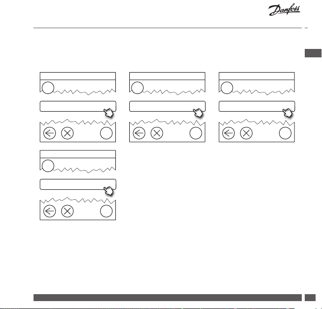
5.3. Rimozione di un dispositivo domotico o di servizio dalla rete
I dispositivi possono essere rimossi dalla rete premendo e tenendo premuto un
pulsante mentre si inserisce/disinserisce l’alimentazione (vedere le illustrazioni).
Premere il pulsante per circa 5 secondi dopo aver ricollegato l’alimentazione.
^
living connect® Danfoss Link™ PR CF-RU
Danfoss Icon™ RT Danfoss Link™ HC Danfoss Link™ BR
SU
N
NL
Danfoss Link™ HR Danfoss CCM/DCM/DLG Danfoss Link™ FT/S
01/2019 VISGL902N Danfoss Heating Solutions
60
1
2
1. Per rimuovere
il dispositivo
2. Per lo
spegnimento

Guida all’installazione Danfoss Link™ CC
Opzioni di servizio
Stanze e dispositivi
Gestisci dispositivi
Rimuovi dispositivi
Metodo alternativo per la rimozione di un dispositivo difettoso o mancante
(solo se/quando il metodo precedente non è possibile): Rimuovere il coperchio
anteriore e premere il pin SETUP per 3 secondi per accedere all’area di servizio.
1
Stanze e dispositivi
?
2
Gestisci dispositivi
3
Rimuovi qualsiasi
?
4
Cancella dispositivo inattivo
?
Per sostituire un dispositivo mantenendone tutte le impostazioni, usare la
funzione Sostituisci qualsiasi dispositivo e seguire le istruzioni indicate sullo
schermo. Usando questa funzione, tutte le impostazioni per quel particolare
dispositivo vengono trasferite alla nuova unità.
Danfoss Heating Solutions VISGL902N 01/2019
IT
?
61

Guida all’installazione Danfoss Link™ CC
!
5.4. Reimpostazione di fabbrica dell’unità Danfoss Link™ CC
L’unità Danfoss Link™ CC può essere ripor tata alle impostazioni
di fabbrica quando tut ti i dispositivi vengono rimossi dalla rete.
Rimuovere il coperchio anteriore e premere e tenere premuto il pulsante di
reset sul lato destro dell’unità Danfoss Link™ CC nché il controllore non
emette un segnale acustico. Ora tutte le stanze sono state cancellate e sono
state ripristinate le impostazioni di fabbrica dell’unità Danfoss Link™ CC.
01/2019 VISGL902N Danfoss Heating Solutions
62

Guida all’installazione Danfoss Link™ CC
Controllo domotico
Personalizza sistema
Wi-Fi e applicazioni
6. Collegamento Wi-Fi e all’applicazione
6.1. Wi-Fi
Una volta terminato il test della rete, l’unità Danfoss Link™ CC è pronta
per essere collegata a una rete Wi-Fi.
IT
1
Impostazioni
?
2
Wi-Fi e applicazioni
?
1. Premere .
2. Selezionare la rete Wi-Fi e immettere la password.
3. Selezionare o deselezionare l’aggiornamento automatico del software.
4. Premere .
Danfoss Heating Solutions VISGL902N 01/2019
3
On
?
63

Guida all’installazione Danfoss Link™ CC
Controllo domotico
Personalizza sistema
Wi-Fi e applicazioni
Opzioni dell'applicazione
Aggiungi applicazione
6.2. Collegamento all’applicazione
Quando l’unità Danfoss Link™ CC è collegata alla rete Wi-Fi con accesso Internet,
può essere collegata a uno smart device mediante l’app Danfoss Link. L’app è
disponibile su Google Play e su App Store.
1
Impostazioni
?
4
Aggiungi applicazione
?
Attenersi alle istruzioni riportate sullo schermo.
01/2019 VISGL902N Danfoss Heating Solutions
64
2
Wi-Fi e applicazioni
5
Collega applicazione
3
Opzioni dell'applicazione
?
?
?

Guida all’installazione Danfoss Link™ CC
Controllo domotico
Personalizza sistema
Wi-Fi e applicazioni
Opzioni dell'applicazione
Rimuovi applicazione
Rimuovi applicazione
6.3. Modica dei dispositivi collegati
I dispositivi collegati devono essere rimossi dal sistema senza la resettare
le impostazioni remote.
1
2
3
IT
Impostazioni
4
Rimuovi applicazione
Danfoss Heating Solutions VISGL902N 01/2019
Wi-Fi e applicazioni
?
?
5
Rimuovi selezionate
?
?
Opzioni dell'applicazione
6
0
Rimuovi tutte
?
?
65

Guida all’installazione Danfoss Link™ CC
Controllo domotico
Personalizza sistema
Wi-Fi e applicazioni
7. Aggiornamento della versione del software
Il software Danfoss Link™ può essere aggiornato. Le nuove versioni del software
vengono pubblicate su www.link.danfoss.com.
Aggiornamento automatico del software:
Se si è attivato il Wi-Fi e si è selezionato l’aggiornamento automatico
del software, Danfoss Link™ verrà aggiornato automaticamente all’ultima
versione disponibile.
Aggiornamento manuale del software:
Scaricare l’aggiornamento del software su una chiavetta USB e inserire
la chiavetta USB nell’apposita porta.
1
Impostazioni
01/2019 VISGL902N Danfoss Heating Solutions
66
?
2
Wi-Fi e applicazioni
3
Opzioni dell'applicazione
?
?

Guida all’installazione Danfoss Link™ CC
Opzioni dell'applicazione
Avvio
Controllo domotico
4
Aggiornamento software
8. Avvisi
Se si verica un avviso o un allarme, sulla schermata di standby verrà
!
visualizzata un’icona di av viso gialla. Seguire la procedura per trovare
maggiori informazioni.
Danfoss Heating Solutions VISGL902N 01/2019
?
!
1
Controllo domotico
? ?
IT
2
Allarmi
?
67

Guida all’installazione Danfoss Link™ CC
8.1. Icone di avviso
I dispositivi collegati devono essere rimossi dal sistema senza la resettare
le impostazioni remote.
Avviso batteria
Livello critico batteria
Livello basso batteria Funzionamento manuale
Limite di temperatura
min. del pavimento
Antimanomissione/
restrizioni abilitate
Il dispositivo
non risponde
Troppi dispositivi
inattivi
Riscaldamento
disattivato
in una stanza
01/2019 VISGL902N Danfoss Heating Solutions
68
Icona per temperatura
del pavimento
Icona per temperatura
ambiente
Icona per valvole
termostatiche

Guida all’installazione Danfoss Link™ CC
9. Speciche tecniche e certicazioni
Danfoss Link™ CC
Tensione operativa 15 VCC ±10%
Consumo di corrente in standby Max. 2 W
Schermo TFT touch screen a colori da 3,5”
Temperatura ambiente Da -10 a +40 °C
Temperatura di immagazzinaggio Da -20 a +65 °C
Temperatura pressione sfera 75 °C
Grado d’inquinamento 2 (uso domestico)
Frequenza di trasmissione 868,42 MHz
Portata di trasmissione in edici normali Fino a 30 m
Wi-Fi 802,11b, g o n (2,4 GHz)
Numero max. di ripetitori in una catena 3
Potenza di trasmissione Max. 1 mw
Classe software A
Classe IP 21
Dimensioni 125 mm × 107 mm × 25 mm
Peso 180 g
Danfoss Heating Solutions VISGL902N 01/2019
IT
69

Guida all’installazione Danfoss Link™ CC
PSU Danfoss Link™ (incassato nella parete)
Tensione operativa 100–250 VCA, 50/60 Hz
Fusibile di protezione consigliato Max. 16 A
Tensione di uscita 15 VCC ±10%
Consumo di corrente in standby Max. 0,15 W
Carico max. 10 W
Speciche dei cavi Consigliati 1,5 mm2, max. 2 x 2,5 mm
Danfoss Link™ NSU (adattatore di rete)
Tensione operativa 100–240 VCA, 50/60 Hz
Fusibile di protezione consigliato Max. 16 A
Tensione di uscita 15 VCC ±10%
Consumo di corrente in standby Max. 0,3 W
Carico max. 7 W
Lunghezza del cavo 2,5 m
01/2019 VISGL902N Danfoss Heating Solutions
70
2

Guida all’installazione Danfoss Link™ CC
Danfoss Link™ BSU (unità di alimentazione a batteria)
Tensione di uscita 15 VCC ±10%
Numero di batterie 10 x AA (non incluse)
L’unità Danfoss Link™ CC è testata per soddisfare i requisiti di sicurezza
ed EMC come specicato in EN60730-1 ed EN60730-2-9.
IT
Danfoss Heating Solutions VISGL902N 01/2019
71

Guida all’installazione Danfoss Link™ CC
10. Istruzioni sullo smaltimento
DICHIARAZIONE DI CONFORMITÀ UE SEMPLIFICATA
Il fabbricante, Danfoss A/S, dichiara che il tipo di apparecchiatura radio Danfoss Link™ CC è conf orme alla
Il testo com pleto della dichi arazione di conf ormità UE è dispon ibile al seguente i ndirizzo Inter net:
01/2019 VISGL902N Danfoss Heating Solutions
72
direttiva 2014/53/UE.
heating.danfoss.comm

Asennusopas Danfoss Link™ CC
Sisältö
1. Pika-asennusohje ...................................................................................... 75
2. Johdanto .................................................................................................... 76
3. Asennusta koskevat ohjeet ...................................................................... 77
3.1. Asianmukainen asennussuunnitelma ..............................................................78
3.2. Virheellinen asennussuunnitelma .....................................................................79
3.3. Miten ja milloin toistimia käytetään? .............................................................. 80
3.4. Toistimien sijoittaminen........................................................................................81
4. Asennusohje .............................................................................................. 83
4.1. Laitteiden lisääminen järjestelmään ............................................................... 84
4.2. Virran kytkeminen ja maan, kielen, päiväyksen
ja ajan asettaminen ................................................................................................ 84
4.3. Asennusvalikon käynnistäminen .......................................................................85
4.4. Verkkovirtaan kytkettyjen laitteiden asennus .............................................85
4.5. Huoltolaitteiden lisääminen ............................................................................... 86
4.6. Paristokäyttöisten laitteiden asennus .............................................................87
4 .7. Huoneiden luominen .............................................................................................87
4.8. Huonelaitteiden lisääminen ............................................................................... 88
4.9. Verkon testaaminen ................................................................................................89
4.10. Asennuksen viimeistely ........................................................................................ 90
Danfoss Heating Solutions VISGL902N 01/2019
FI
73

Asennusopas Danfoss Link™ CC
5. Nykyisen asennuksen muuttaminen ...................................................... 91
5.1. Laitteiden lisääminen nykyiseen huoneeseen .............................................91
5.2. Lämmityksen säätelyparametrien muuttaminen .......................................92
5.3. Huoneen tai huoltolaitteen poistaminen verkosta ................................... 94
5.4. Danfoss Link™ CC:n tehdasasetusten palautus ........................................... 96
6. Wi-Fi- ja ohjelmayhteys ............................................................................ 97
6.1. Yhdistä Wi-Fi-verkkoon .........................................................................................97
6.2. Yhdistä ohjelmaan .................................................................................................. 98
6.3. Muokkaa kytkettyjä laitteita ............................................................................... 99
7. Ohjelmistoversion päivittäminen ......................................................... 100
8. Varoitukset............................................................................................... 101
8.1. Varoituskuvakkeet ................................................................................................ 102
9. Tekniset tiedot ja hyväksynnät ............................................................. 103
10. Hävitysohjeet........................................................................................... 106
01/2019 VISGL902N Danfoss Heating Solutions
74

Asennusopas Danfoss Link™ CC
K”
1. Pika-asennusohje
1. 2.
^
^
Asenna ensin kaikki verkkovirtaan
kytketyt laitteet ja liitä ne verkkoon.
3.
”O
Suorita verkkotesti, kun Danfoss
Link™ CC on lopullisessa
Luo huoneet ja lisää paristokäyttöiset laitteet yksitellen.
4.
Käännä
auki ja
Manual
Information
asenna
Updates
paikalleen
www.link.danfoss.com
Welcome
Wilkommen
Velkommen
Välkommen
Powitanie
Bienvenue
Information
Manual
Updates
www.link.danfoss.com
Asenna kannatin Danfoss Link™
CC:hen.
asennuspaikassaan.
Vihjeet!
• Näppäintä ? voidaan käyttää milloin tahansa asennuksen aikana.
• Hae aina ennen asennusta uusin ohjelmistoversio osoitteesta
www.link.danfoss.com. Katso luku 7: Ohjelmistoversion päivittäminen.
Danfoss Heating Solutions VISGL902N 01/2019
+-+
Welkom
Bienvenido
Vitán
Teretulnud
Gaidīts
Tervetuloa
-
FI
75

Asennusopas Danfoss Link™ CC
!
2. Johdanto
Danfoss Link™ on ohjelmoitava, langaton
asuinrakennusten (enimmäispinta-ala noin 300 m2)
15.7.
10.15
Käyttö- ja huonelaitteiden mukana toimitetuissa ohjeissa selostetaan
laitteen kytkeminen verkkoon. Ohjeessa mainitaan myös, onko laite
käyttö- vai huonelaite.
01/2019 VISGL902N Danfoss Heating Solutions
76
lämmitysjärjestelmien ohjausjärjestelmä.
Keskusyksikkö koostuu Danfoss Link™
CC -keskusyksiköstä, joka on varustettu
värikosketusnäytöllä, jolla järjestelmän kaikkia osia voi
ohjata.
Tässä asennusoppaassa selostetaan kaikki Danfoss
Link™ CC:n tiedot sekä käyttöönotto. Oppaassa
esitetään suositukset ja ohjeet, jotka on otettava
huomioon langattoman järjestelmän käsittelyssä.
Lisäksi oppaassa selostetaan järjestelmän asetusten
määrittäminen.

Asennusopas Danfoss Link™ CC
3. Asennusta koskevat ohjeet
Signaalin voimakkuus riittää useimpiin käyttötarkoituksiin, mutta langattomat
signaalit heikentyvät Danfoss Link™ CC:n ja huonelaitteiden välillä ja signaalien
tiellä olevat esteet vaihtelevat rakennuksittain.
Ota seuraavat seikat huomioon suunnittelussa ja asennuksessa:
• Laitteiden väli saa olla enintään 30 metriä vapaassa tilassa.
• Vastaanottimet on hyvä sijoittaa lähettimen vastaiselle tai viereiselle seinälle.
• Metallirakenteet voivat heikentää langattomia signaaleja.
• Raudoitetut betoniseinät ja -lattiat vaimentavat signaalia merkittävästi, mutta
lähes kaikentyyppiset rakenteet heikentävät sitä jossain määrin.
• Myös rakennuksen muodot, kuten kulmat, voivat estää signaalin kulkua joko
pidentämällä matkaa, joka sen on kuljettava, tai haittaamalla sen heijastumista.
Huom:
Danfoss suosittelee laatimaan ennen asennusta asennussuunnitelman, joka auttaa
hahmottamaan eri huoneisiin tulevat laitteet ja niiden sijoituspaikat.
Danfoss Heating Solutions VISGL902N 01/2019
FI
77

Asennusopas Danfoss Link™ CC
3.1. Asianmukainen asennussuunnitelma
Danfoss Link™ CC:n ja muiden langattomien Danfoss-yksikköjen välillä
ei saa olla metalliesineitä.
Danfoss Link™ CC asennetaan mahdollisimman keskelle lattiatasoa
(enintään 30 metriä vapaata tilaa laitteiden välillä).
Ohjaa langaton signaali seinien läpi lyhyintä mahdollista diagonaalista
reittiä.
Danfoss
Icon™ RT
(huonelaite)
Metalliesine
01/2019 VISGL902N Danfoss Heating Solutions
78
living connect®
(huonelaite)
Danfoss Link™ CC
-keskusyksikkö
living connect®
(huonelaite)
Danfoss
Link™ HC
(huoltolaite)

Asennusopas Danfoss Link™ CC
!
!
!
3.2. Virheellinen asennussuunnitelma
Metalliesineitä Danfoss Link™ CC:n ja muiden langattomien
Danfoss-yksikköjen välillä
Danfoss Link™ CC asennettu virheellisesti.
Diagonaalinen seinien lävistys.
Danfoss
Icon™ RT
(huonelaite)
living connect®
(huonelaite)
Danfoss
Link™ HC
(huoltolaite)
FI
Metalliesine
!
living connect®
(huonelaite)
Danfoss Heating Solutions VISGL902N 01/2019
!
!
Danfoss Link™ CC
-keskusyksikkö
79

Asennusopas Danfoss Link™ CC
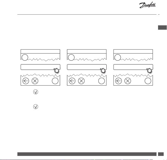
3.3. Miten ja milloin toistimia käytetään?
Mikä on toistimen tarkoitus?
Toistin vahvistaa langattoman signaalin, kun Danfoss Link™ CC:n ja muiden
langattomien Danfoss-yksikköjen välille ei voida muodostaa riittävän
voimakasta yhteyttä.
Milloin toistinta tarvitaan?
1. Suorita asennus ja suorita verkkotesti (kohdan 4.9 mukaisesti). Jos jossakin
laitteessa on vika, liitä verkkoon toistin (CF-RU) Danfoss Link™ CC:n ja viallisten
laitteiden välille.
2. Vaihtoehtoisesti jatka suunnittelua. Jos vastaat “kyllä” vähintään yhteen seuraavista kysymyksistä, Danfoss suosittelee liittämään toistimen asennuksen
alkuun (katso 3.4).
• Ovatko väliseinät tai kerrosten väliset rakenteet teräsvahvisteista betonia?
• Onko Danfoss Link™ CC:n ja viimeisen laitteen välinen etäisyys yli 20 metriä
ja onko signaalin läpäistävä enemmän kuin kaksi vahvaa seinää (kiviseinää
tai vahvistamatonta betoniseinää).
• Onko Danfoss Link™ CC:n ja viimeisen laitteen välinen etäisyys yli 25 metriä
ja onko signaalin läpäistävä enemmän kuin kaksi kevyttä seinää (kipsilevy
tai puu).
• Onko vapaa näkyvyys yli 30 metriä?
Toistin (CF-RU) voidaan tilata Danfossin tilausnumerolla 088U0230 taiLVI-numerolla 2029034
Huom:
Nämä ovat vain viitteellisiä ohjeita, koska langattomaan yhteyteen vaikuttavat
monet eri seikat.
01/2019 VISGL902N Danfoss Heating Solutions
80

Asennusopas Danfoss Link™ CC
3.4. Toistimien sijoittaminen
Suunnittelunäkymä - yksikerroksinen rakennus
Teräsvahvisteinen
betoniseinä
^
^
21
Signaali
estynyt
Danfoss Link™ CC
-keskusyksikkö
Vahva signaali
Vahva signaali
^
^
21
Toistin
Danfoss Heating Solutions VISGL902N 01/2019
FI
81

Asennusopas Danfoss Link™ CC
Poikkileikkausnäkymä - rakennus, jossa on vähintään kaksi kerrosta
2. kerros
Toistin
Vahva signaali
1. kerros
^
Vahva signaali
^
21
01/2019 VISGL902N Danfoss Heating Solutions
82
Danfoss Link™ CC
-keskusyksikkö
Signaali estynyt
^
^
21

Asennusopas Danfoss Link™ CC
!
4. Asennusohje
Danfoss Link™ CC saa virtansa joko
seinään asennettavalla kiinteällä
PSU-virtalähteellä tai NSU-verkkovirtalähteellä.
Danfoss Link™ CC:n asennus PSU-virtalähteen yhteydessä
• Pidä PSU:ta seinäkotelon päällä ja merkitse neljä ruuvin reikää.
Varmista, että yläreunat ovat kohdakkain.
• Poraa reiät ja laita niihin proput.
• Liitä PSU takapuolella olevan kytkentäkaavion mukaisesti.
• Kiinnitä PSU paikoilleen neljällä ruuvilla.
Danfoss Link™ CC:n asennus NSU-virtalähteen
yhteydessä
• Pidä asennuslevyä seinää vasten ja merkitse neljä ruuvin reikää. Varmista, että yläreunat ovat kohdakkain.
• Poraa reiät ja laita niihin proput.
• Kiinnitä asennuslevy neljällä ruuvilla.
Älä asenna Danfoss Link™ CC:tä vielä!
• Liitä NSU-pistotulppa pistorasiaan.
Ei saa
asentaa
kylpyhuo-
neisiin.
Vältä altista -
masta suoralle
auringonva-
lolle
140-170 cm
FI
Asennus-
korkeus:
UP
PSU
UP
NSU
Danfoss Heating Solutions VISGL902N 01/2019
83

Asennusopas Danfoss Link™ CC
Valitse kieli
Valitse maa
Aseta päiväys ja aika.
4.1. Laitteiden lisääminen järjestelmään
Lisättäessä laitteita Danfoss Link™ -järjestelmään Danfoss Link™ CC:n ja laitteen
välinen etäisyys saa olla enintään 1,5 m. Ehdon täyttämisessä auttaa asennustyökalu, Danfoss Link™ BSU -paristovirtalähde.
1. Liu’uta kansi auki ja asenna paristot.
2. Liu’uta kansi takaisin paikalleen ja kiinnitä Danfoss Link™
BSU -paristoyksikkö Danfoss Link™ CC:n takaosaan. Kun
olet valmis ottamaan laitteen käyttöön, käännä Danfoss
Link™ BSU:n virtakytkin ON-asentoon.
Nyt Danfoss Link™ CC käynnistyy. Tämä vie noin 30 sekuntia.
+
x 10
-
1,5 V
AA
01
BSU
Paristoyksikkö (BSU) voidaan tilata Danfossin tilausnumerolla 014G0262 tai
LVI-numerolla 4035209.
4.2. Virran kytkeminen ja maan, kielen, päiväyksen
ja ajan asettaminen
1
Vieritä alas ja valitse
?
01/2019 VISGL902N Danfoss Heating Solutions
84
2
Vieritä alas ja valitse
3
Aseta päiväys ja aika.
?
?

Asennusopas Danfoss Link™ CC
4.3. Asennusvalikon käynnistäminen
• Irrota Danfoss Link™ CC:n etukansi tarttumalla siihen reunojen läheltä ja vetämällä se varovasti pois paikaltaan.
• Paina asetuspainiketta (SETUP) 3 sekuntia huoltoalueelle
pääsemiseksi.
4.4. Verkkovirtaan kytkettyjen laitteiden asennus
Kytke ensin virta kaikkiin verkkovirtaa käyttäviin laitteisiin ja sitten
tarvittaviin toistimiin.
Huom: Jos käytössä on Danfoss Link™ HC, kytke kaikki toimilaitteet ( TWA), ennen
kuin kytket yksikön verkkovirtaan. Katkaisinreleet näkyvät vain loppukäyttäjän
valikossa.
• Muodosta pariyhteys laitteista Danfoss Link™ CC:hen.
• Aloita lähimpänä Danfoss Link™ CC:tä olevasta
laitteesta ja etene kauemmas.
FI
Danfoss Heating Solutions VISGL902N 01/2019
85

Asennusopas Danfoss Link™ CC
!
Ylläpitoasetukset
Huoneet ja laitteet
Lisää ohjauslaite
4.5. Huoltolaitteiden lisääminen
Lisää ensin erillinen toistin!
Danfoss Link™ tukee monia erityyppisiä huoltolaitteita ja niiden toimintoja,
kuten muiden sähkölaitteiden yksinkertaisia virtakytkimiä, toistimia ja
vesikiertojärjestelmien hallintalaitteita ja muita alijärjestelmiä.
1
Huoneet ja laitteet
?
Muokkaa laitteen nimeä
2
Lisää huoltolaite
3
Aloita rekisteröinti
?
4
Syötä/muokkaa laitteen nimeä
?
01/2019 VISGL902N Danfoss Heating Solutions
86
?

Asennusopas Danfoss Link™ CC
^
Ylläpitoasetukset
Huoneet ja laitteet
Muokkaa laitteen nimeä
4.6. Paristokäyttöisten huoltolaitteiden asennus
Luo huoneet ja lisää paristokäyttöiset
huonelaitteet määritettyihin huoneisiin. Tämä voidaan tehdä mielivaltai-
^
sessa järjestyksessä.
4.7. Huoneiden luominen
Danfoss suosittelee luomaan ja lisäämään yhden huoneen laitteet kerralla
ja siirtymään sitten seuraavaan huoneeseen.
+-+
-
FI
1
Huoneet ja laitteet
2
Lisää uusi huone
?
Vihje! Yleisten huonenimien luettelo on saatavana täällä
Danfoss Heating Solutions VISGL902N 01/2019
3
Syötä/muokkaa huoneen nimeä
?
ABC
.
?
87

Asennusopas Danfoss Link™ CC
Huoneen laitteet
Lisää huonelaite
Huoneen laitteet
4.8. Huonelaitteiden lisääminen
Huonelaite säätää sen huoneen lämpötilaa, johon laite on asennettu. Kaikki
laitteet on konguroitava aiemman asennussuunnitelman mukaisesti signaalin
reitin varmistamiseksi.
Muokkaa huoneen asetuksia
1
2
3
Huoneen laitteet
?
Lisää laite
Aloita rekisteröinti
?
Huom:
4
Kongurointi on voimassa
Paina
Danfoss Link™ CC valitsee
säätelyperiaatteen automaattisesti
huoneen laitteiden tyyppien perusteella.
Tietoa säätelyperiaatteen
muuttamisesta on kohdassa
?
01/2019 VISGL902N Danfoss Heating Solutions
88
5.2 Lämmityksen säätelyparametrien
muuttaminen.
?

Asennusopas Danfoss Link™ CC
Ylläpitoasetukset
Tila ja diagnoosit
Langattoman verkon tila
4.9. Verkon testaaminen
Asennuksen päätyttyä verkko on testattava sen varmistamiseksi, että viestintä
Danfoss Link™ CC:n ja kaikkien lisättyjen laitteiden kesken toimii luotettavasti.
Huom: Älä suorita verkkotestiä ennen kuin Danfoss Link™ CC on kiinnitetty lopulliseen paikkaansa. Lisäksi varmista, että kaikki living connects® -k ytkennät ovat pois
asennustilasta (lisätietoja on living connect® -ohjekohdassa).
1. Kytke paristoyksikkö pois päältä.
2. Aseta Danfoss Link™ CC aiemmin asennetulle
asennuslevylle.
3. Nyt Danfoss Link™ CC käynnistyy.
4. Poista etukansi ja paina SETUP-painiketta
3 sekunnin ajan, jotta pääset huoltoalueelle.
Jos verkon toimivuus on epävarmaa, kannattaa suorittaa verkkotesti ennen
asennuksen tekemistä kokonaan valmiiksi.
FI
1
Tila ja diagnoosit
Danfoss Heating Solutions VISGL902N 01/2019
2
Verkko
?
?
3
Aloita verkon testaus
?
89

Asennusopas Danfoss Link™ CC
Verkon testauksen lopussa Danfoss Link™ CC odottaa kaikkien paristokäyttöisten
laitteiden heräämistä ja ilmoittautumista. Noudata näytössä annettavia ohjeita.
Jos verkon testauksessa ei esiinny ongelmia, muita toimia ei tarvita. Jos verkon
testaus etenee hitaasti, Danfoss Link™ CC aloittaa ohjatun vianetsinnän ja antaa
neuvoja prosessin nopeuttamiseksi.
4.10. Asennuksen viimeistely
Sulje asennus painamalla SETUP-painiketta.
10:15
01/2019 VISGL902N Danfoss Heating Solutions
90
?

Asennusopas Danfoss Link™ CC
Ylläpitoasetukset
Huoneet ja laitteet
Hallitse nykyisiä huoneita
Muokkaa huoneen asetuksia
Huoneen laitteet
Lisää huonelaite
!
5. Nykyisen asennuksen muuttaminen
5.1. Laitteiden lisääminen nykyiseen huoneeseen
Poista etukansi ja paina SETUP-painiketta 3 sekunnin ajan, jotta pääset
huoltoalueelle.
1
2
3
FI
Huoneet ja laitteet
4
Huoneen laitteet
Jatka, kunnes kaikki uudet laitteet on lisätty haluttuun huoneeseen.
Testaa verkko aina kokoonpanon muokkaamisen jälkeen.
Danfoss Heating Solutions VISGL902N 01/2019
Hallitse nykyisiä huoneita
?
5
Lisää laite
?
Muuta nykyisten huoneiden asetuksia
?
6
?
?
Aloita rekisteröinti
?
91

Asennusopas Danfoss Link™ CC
Ylläpitoasetukset
Huoneet ja laitteet
Hallitse nykyisiä huoneita
Muokkaa huoneen asetuksia
Lämmityksen säätely
5.2. Lämmityksen säätelyparametrien muuttaminen
Poista etukansi ja paina SETUP-painiketta 3 sekunnin ajan, jotta pääset
huoltoalueelle.
1
Huoneet ja laitteet
?
4
Lämmityksen säätely
?
2
Hallitse nykyisiä huoneita
?
5
Valitse asetus
?
3
Valitse huone
• Ennakoinnin toimintaperiaate: Ennakoinnin valitsemalla järjestelmä ennakoi
lämmityksen aloittamisen automaattisesti, jotta haluttu huoneen lämpötila
saavutetaan haluttuun aikaan.
• Lattian maksimilämpötila: Oletusasetus on 35 astetta (sähköinen
lattialämmitys).
• Säätelytyyppi: on käytettävissä vain sähkölämmityksen yhteydessä.
01/2019 VISGL902N Danfoss Heating Solutions
92
?

Asennusopas Danfoss Link™ CC
Huom: Voit valita seuraavien säätelytyyppien välillä käyttämällä koodia [0044]:
Huoneanturi (säätelee vain huoneen lämpötilan mukaan) - jos vain Danfoss
Icon™ RT on asennettuna (vesikiertoinen lattialämmitys) tai jos asennettuna ovat
Danfoss Icon™ RT ja Danfoss Link™ FT (sähkölämmitys).
Lattia-anturi (säätelee vain lattian lämpötilan mukaan ) - jos vain Danfoss Link™
FT/S on asennettuna.
Yhdistetty lattia-huoneanturi (takaa lattian minimilämpötilan ja säätelee
huoneen lämpötilaa) - Danfoss Icon™ RT ja Danfoss Link™ FT/S ovat asennettuina.
Jos kyseessä on vesikiertoinen lattialämmitys, ota huomioon lattian valmistajan
ilmoittama suurin sallittu lattian lämpötila. Tämä voidaan varmistaa asentamalla
termostaatin avulla ohjattu sekoitusventtiili.
Danfoss Heating Solutions VISGL902N 01/2019
FI
93

Asennusopas Danfoss Link™ CC
^
5.3. Huoneen tai huoltolaitteen poistaminen verkosta
Laitteita voi poistaa verkosta pitämällä painiketta painettuna sekä katkaisemalla
samalla virran ja kytkemällä sen uudelleen päälle (ks. kuvat). Paina painiketta
noin 5 sekunnin ajan, kun olet kytkenyt virran uudelleen päälle.
^
living connect® Danfoss Link™ PR CF-RU
Danfoss Icon™ RT Danfoss Link™ HC Danfoss Link™ BR
YLÖS
S
SE
Danfoss Link™ HR Danfoss CCM/DCM/DLG Danfoss Link™ FT/S
01/2019 VISGL902N Danfoss Heating Solutions
94
1
2
1. Laitteen
poistaminen
2. Virran sam muttaminen

Asennusopas Danfoss Link™ CC
Ylläpitoasetukset
Huoneet ja laitteet
Hallitse laitteita
Poista laitteita
Vaihtoehtoinen tapa viallisen tai puuttuvan laitteen poistamiseen (vain jos
edellä kuvattu tapa ei ole mahdollinen): Poista etukansi ja paina SETUP-paini-
ketta 3 sekunnin ajan, jotta pääset huoltoalueelle.
1
Huoneet ja laitteet
?
2
Hallitse laitteita
3
Poista laite
?
4
Poista toimimaton laite
?
Jos haluat vaihtaa laitteen ja säilyttää laitteen asetukset, käytä toimintoa Vaihda
jokin laite ja toimi näyttöön tulevien ohjeiden mukaisesti. Tämä asetus siirtää
laitteen kaikki asetukset uuteen laitteeseen.
Danfoss Heating Solutions VISGL902N 01/2019
FI
?
95

Asennusopas Danfoss Link™ CC
!
5.4. Danfoss Link™ CC:n tehdasasetusten palautus
Danfoss Link™ CC:n tehdasasetukset voidaan palauttaa, kun kaikki laitteet
on poistettu verkosta.
Poista etukansi ja paina Danfoss Link™ CC:n oikeassa sivussa olevaa nollauspainiketta, kunnes kuulet merkkiäänen. Kaikki huoneet on nyt poistettu, ja Danfoss
Link™ CC:n tehdasasetukset on palautettu.
01/2019 VISGL902N Danfoss Heating Solutions
96

Asennusopas Danfoss Link™ CC
Talon ohjaus
Mukauta järjestelmä
Wi-Fi ja ohjelmat
6. Wi-Fi- ja ohjelmayhteys
6.1. Yhdistä Wi-Fi-verkkoon
Verkkotestin päätyttyä onnistuneesti Danfoss Link™ CC:n voi kytkeä
Wi-Fi-verkkoon.
1
2
3
FI
Asetukset
Wi-Fi ja ohjelmat
?
1. Paina .
2. Valitse Wi-Fi-verkko ja syötä salasana
3. Valitse, päivitetäänkö ohjelmisto automaattisesti.
4. Paina .
Danfoss Heating Solutions VISGL902N 01/2019
Päällä
?
?
97

Asennusopas Danfoss Link™ CC
Talon ohjaus
Mukauta järjestelmä
Wi-Fi ja ohjelmat
Ohjelma-asetukset
Lisää ohjelma
6.2. Yhdistä ohjelmaan
Kun Danfoss Link™ CC on yhdistetty Wi-Fi-verkkoon, joka on Internet-yhteydessä, se voidaan kytkeä älylaitteeseen Danfoss Link -ohjelman avulla. Ohjelma
on saatavilla Google Play -palvelussa ja App Storessa.
1
Asetukset
?
4
Lisää ohjelma
?
Noudata näytössä annettavia ohjeita.
01/2019 VISGL902N Danfoss Heating Solutions
98
2
Wi-Fi ja ohjelmat
5
Yhdistä ohjelma
3
Ohjelma-asetukset
?
?
?

Asennusopas Danfoss Link™ CC
Talon ohjaus
Mukauta järjestelmä
Wi-Fi ja ohjelmat
Ohjelma-asetukset
Poista ohjelma
Poista ohjelma
6.3. Muokkaa kytkettyjä laitteita
Kytketyt laitteet voidaan poistaa järjestelmästä nollaamatta kaikkia etäasetuksia.
1
4
Poista ohjelma
Danfoss Heating Solutions VISGL902N 01/2019
Asetukset
2
Wi-Fi ja ohjelmat
?
?
5
Poista valittu
3
Ohjelma-asetukset
6
Poista kaikki
FI
?
OR
?
?
?
99

Asennusopas Danfoss Link™ CC
Talon ohjaus
Mukauta järjestelmä
Wi-Fi ja ohjelmat
7. Ohjelmistoversion päivittäminen
Danfoss Link™ -ohjelmistoon tarjotaan päivityksiä Internetissä. Uudet
ohjelmistoversiot voi ladata ilmaiseksi osoitteesta ww w.link.danfoss.com.
Ohjelmistoversion automaattinen päivittäminen:
Jos olet ottanut käyttöön Wi-Fi-yhteyden ja valinnut Automaattinen ohjelmistopäivitys, Danfoss Link™ päivittää ohjelmiston automaattisesti uusimpaan
versioon.
Ohjelmistoversion manuaalinen päivittäminen:
Lataa ohjelmistopäivitys USB-muistitikulle ja aseta USB-muistitikku USB-porttiin.
1
Asetukset
?
01/2019 VISGL902N Danfoss Heating Solutions
100
2
Wi-Fi ja ohjelmat
3
Ohjelma-asetukset
?
?
 Loading...