

Page 1
MAKING MODERN LIVING POSSIBLE
DANFOSS HEATING SOLUTIONS
Danfoss Link™ CC Central Controller
Installation Guide
Page 2

Page 3
Installation Guide Danfoss Link™ CC - Installation
Installation Guide. . . . . . . . . . . . . . . . . . . . . . . . . . . . . . . . . . . . . . . . . . . . . . . . . . . . . . . . . . . . . . 3
Installationsanleitung. . . . . . . . . . . . . . . . . . . . . . . . . . . . . . . . . . . . . . . . . . . . . . . . . . . . . . . . . 17
Guide d’installation . . . . . . . . . . . . . . . . . . . . . . . . . . . . . . . . . . . . . . . . . . . . . . . . . . . . . . . . . . . 31
Installationsmanual. . . . . . . . . . . . . . . . . . . . . . . . . . . . . . . . . . . . . . . . . . . . . . . . . . . . . . . . . . . 45
Installationshandbok
. . . . . . . . . . . . . . . . . . . . . . . . . . . . . . . . . . . . . . . . . . . . . . . . . . . . . . . . . 59
Asennusohje . . . . . . . . . . . . . . . . . . . . . . . . . . . . . . . . . . . . . . . . . . . . . . . . . . . . . . . . . . . . . . . . . 73
Installatiehandleiding . . . . . . . . . . . . . . . . . . . . . . . . . . . . . . . . . . . . . . . . . . . . . . . . . . . . . . . . 87
Instrukcja instalacji . . . . . . . . . . . . . . . . . . . . . . . . . . . . . . . . . . . . . . . . . . . . . . . . . . . . . . . . . . 101
Instalační příručka . . . . . . . . . . . . . . . . . . . . . . . . . . . . . . . . . . . . . . . . . . . . . . . . . . . . . . . . . . . 115
GB
DE
FR
DK
SE
FI
NL
PL
CZ
VISGL45X © Danfoss 04/2011
3
Page 4
Installation Guide Danfoss Link™ CC - Introduction
Index
Introduction
Installation
Configuration
1: Adding devices to the system. . . . . . . . . . . . . . . . . . . . . . . . . . . . . . . . . . . . . . . . . . . . . . . 6
2: Set country, language and date/time . . . . . . . . . . . . . . . . . . . . . . . . . . . . . . . . . . . . . . . . . 6
3: Start up the installation menu . . . . . . . . . . . . . . . . . . . . . . . . . . . . . . . . . . . . . . . . . . . . . . 6
4: Create rooms . . . . . . . . . . . . . . . . . . . . . . . . . . . . . . . . . . . . . . . . . . . . . . . . . . . . . . . . . 7
5: Purpose of adding repeaters . . . . . . . . . . . . . . . . . . . . . . . . . . . . . . . . . . . . . . . . . . . . . . . 7
6: Adding devices . . . . . . . . . . . . . . . . . . . . . . . . . . . . . . . . . . . . . . . . . . . . . . . . . . . . . . . . 8
7: Adding service devices . . . . . . . . . . . . . . . . . . . . . . . . . . . . . . . . . . . . . . . . . . . . . . . . . . . 9
8: Perform network test . . . . . . . . . . . . . . . . . . . . . . . . . . . . . . . . . . . . . . . . . . . . . . . . . . . 10
9: Finalise installation . . . . . . . . . . . . . . . . . . . . . . . . . . . . . . . . . . . . . . . . . . . . . . . . . . . . 10
Modifying an existing Installation
1: Adding devices to an existing room. . . . . . . . . . . . . . . . . . . . . . . . . . . . . . . . . . . . . . . . . . 11
2: Changing parameters for Heat Regulation . . . . . . . . . . . . . . . . . . . . . . . . . . . . . . . . . . . . . 12
3: Removing / Resetting a device . . . . . . . . . . . . . . . . . . . . . . . . . . . . . . . . . . . . . . . . . . . . . 13
4: Factory reset of Central Controller . . . . . . . . . . . . . . . . . . . . . . . . . . . . . . . . . . . . . . . . . . . 13
Upgrading software version
Warnings
Technical specifications
Disposal instructions
. . . . . . . . . . . . . . . . . . . . . . . . . . . . . . . . . . . . . . . . . . . . . . . . . . . . . . . . . . . . . 4
. . . . . . . . . . . . . . . . . . . . . . . . . . . . . . . . . . . . . . . . . . . . . . . . . . . . . . . . . . . . . . 5
. . . . . . . . . . . . . . . . . . . . . . . . . . . . . . . . . . . . . . . . . . . . . . . . . . 14
. . . . . . . . . . . . . . . . . . . . . . . . . . . . . . . . . . . . . . . . . . . . . . . . . . . . . . . . . . . . . . . 15
. . . . . . . . . . . . . . . . . . . . . . . . . . . . . . . . . . . . . . . . . . . . . . . . . . . . . 16
. . . . . . . . . . . . . . . . . . . . . . . . . . . . . . . . . . . . . . . . . . . . . . . . . . . . . . . 16
Introduction
4
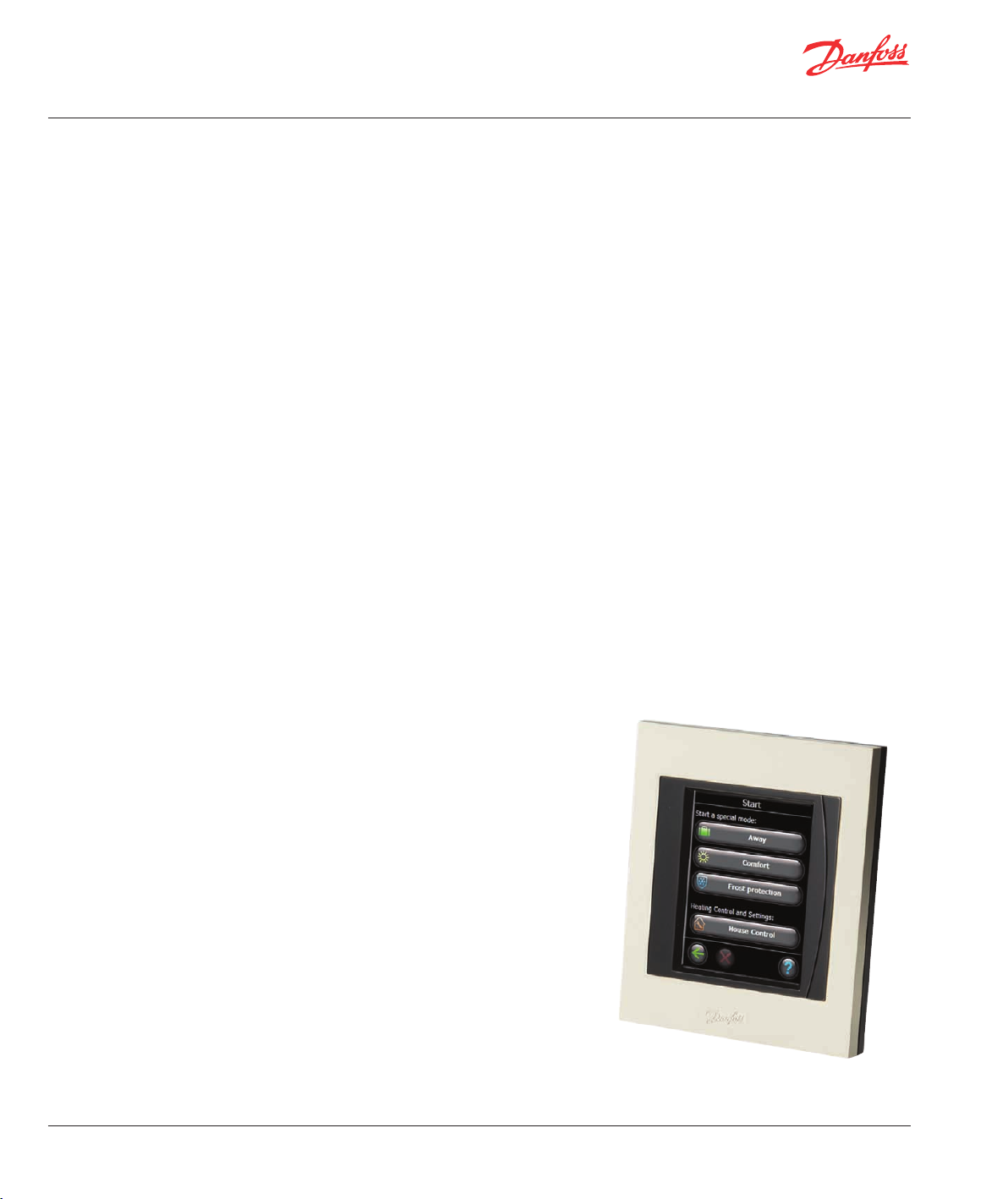
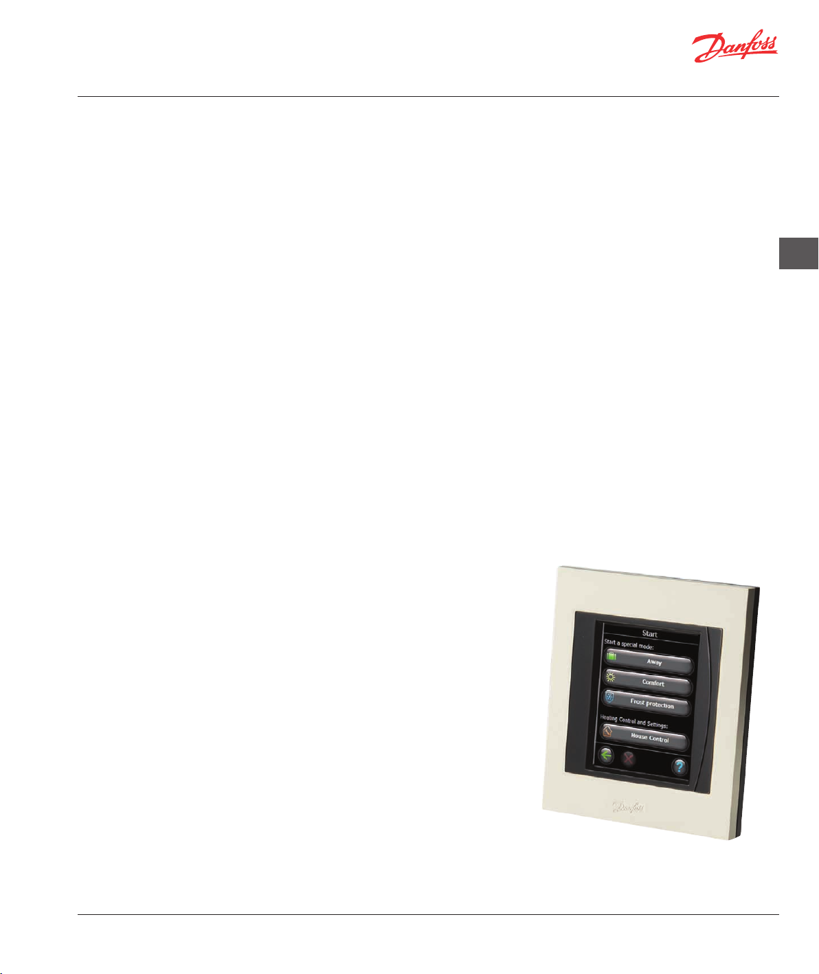
Danfoss Link™ is a wireless control system for a
variety of heating systems.
The central controlling unit is the Danfoss Link™
CC (Central Controller) equipped with a colour
touch screen. From this you can control the entire
installation.
The Danfoss Link™ CC communicates wirelessly with
all other Link devices in the installation.
VISGL45X © Danfoss 04/2011
Page 5
Installation Guide Danfoss Link™ CC - Installation
Installation
The Danfoss Link™ wireless system’s transmission
range is sufficient for most applications; however
each building has different obstacles affecting communication and maximum transmission distance.
If communication problems occur Danfoss suggests
that accessories would be required to support the
system, such as repeaters. In exceptional cases the
wireless system may not be suitable for your installation.
Note! Do not power the Devilink™ CC until the manual tells you to do so.
Do not remove the protective film on the touch screen, the end user should do this.
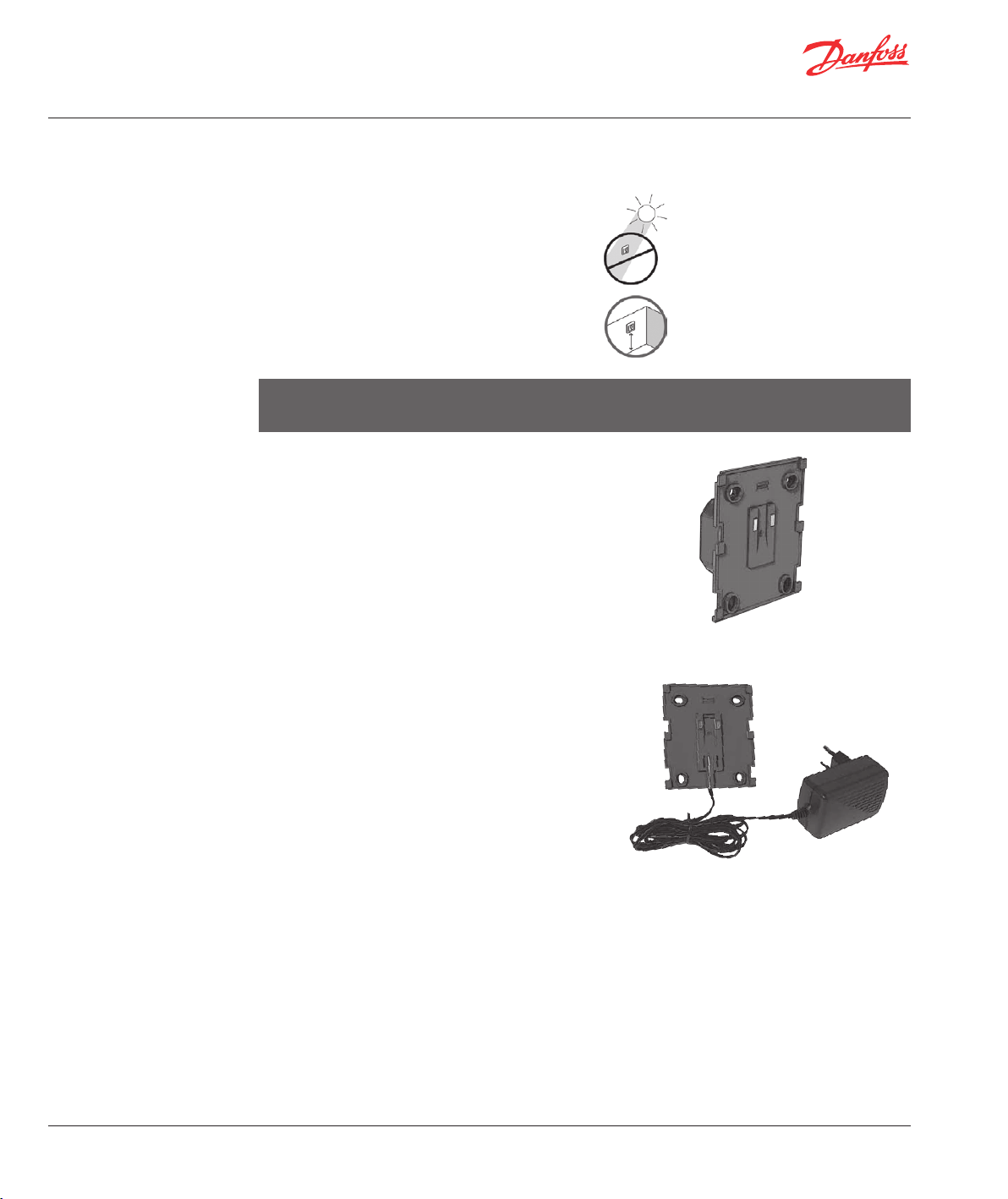
Danfoss Link™ CC can be installed with either a PSU
(in-wall power supply) or a NSU (net power supply.
Installing Danfoss Link™ CC with In-Wall PSU:
• Hold the PSU over the wall box and mark up the 4
screw holes.
Make sure the top is level.
• Drill holes and put fitting plugs in.
• Connect the PSU according to the connection
diagram on the back side.
• Mount the PSU with the 4 screws.
Installing Danfoss Link™ CC with NSU:
• Hold the mounting plate on the wall and mark up
the 4 screw holes. Make sure the top is level.
• Drill holes and put fitting plugs in.
• Mount the mounting plate with the 4 screws.
Do not mount the Danfoss Link™ CC yet!
• Connect the NSU to a power outlet.
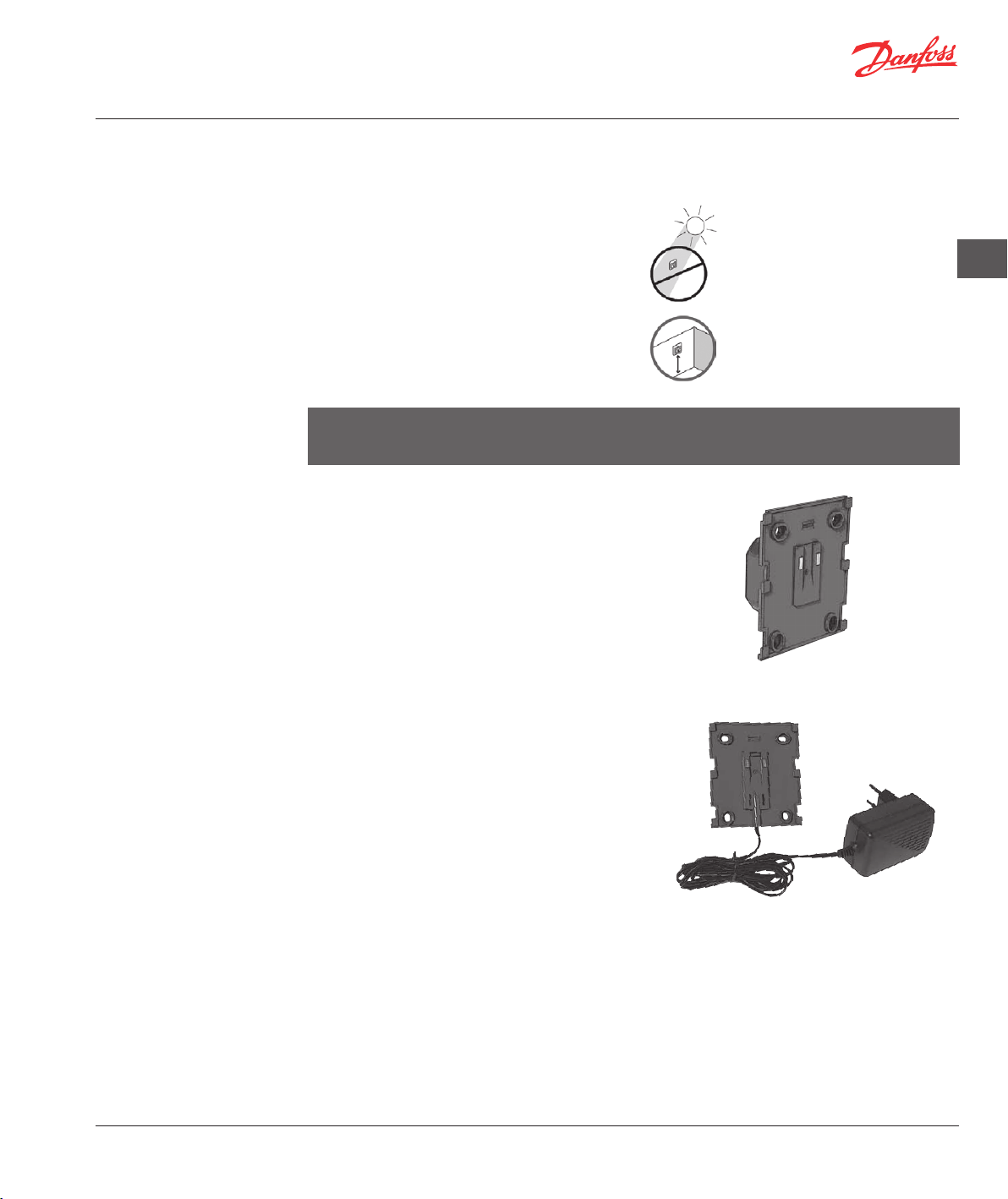
Please be aware of the following, when installing
Danfoss Link™ CC:
Do not install Danfoss Link™ CC,
where it will be subject to direct
sunlight.
The installation height should
typically be between 140-170 cm.
Danfoss Link™ PSU (in-wall Power Supply)
GB
VISGL45X © Danfoss 04/2011
Danfoss Link™ NSU (Net Power Supply)
5
Page 6
Installation Guide Danfoss Link™ CC - Configuration
1: Adding devices to the
system
2: Set country, language
and date/time
Note! Do not configurate the Danfoss Link™ CC until all room devices have been mounted.
When adding devices to the Danfoss Link system,
the distance between CC and device must not
exceed 1.5 m. To accomplish this an installation tool
is offered: Danfoss Link BSU Battery Supply Unit.
Put 10 fresh AA alkaline batteries in the BSU by sliding off the lid.
Be aware of the correct battery polarity.
Slide the lid back on and attach the BSU battery
pack onto the back of the Danfoss Link™ CC. When
you are ready to do the commissioning, turn the
switch located on the BSU to the ON position.
Danfoss Link™ CC will now start up. This might take
several minutes - please be patient . . .
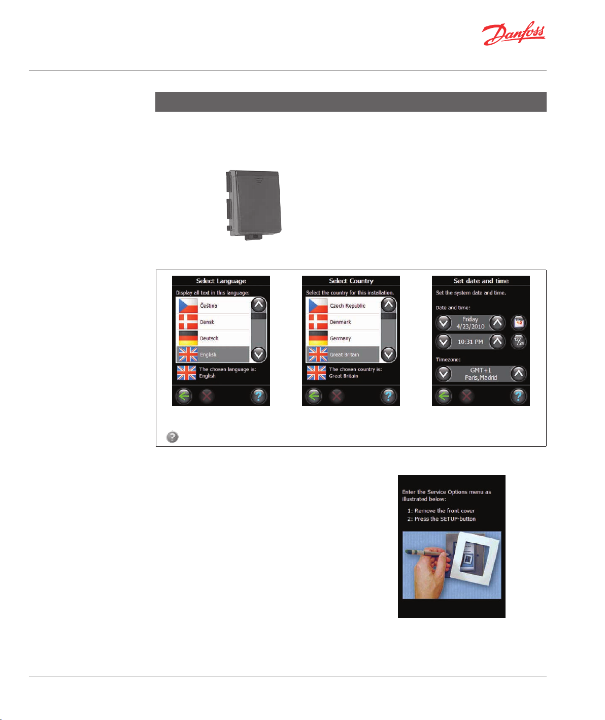
3: Start up the
installation menu
6
1. Select Language. 2. Select Country 3. Set Date and Time
lights up, a help text is available and provides you with a description to the process, which is in progress.
If
Remove the front cover of the Danfoss Link™ CC by
gently pulling it off. Press and hold the setup pin for
3 seconds to start the installer menu.
Danfoss Link can control attached devices in two
different modes:
1. Heating regulation: Control of room heating
devices - more information see Configuration 4:
Create rooms.
2. ON/OFF Functions: Scheduled ON and OFF
control of various electrical devices - more
information see Configuration 7: Adding service
devices.
VISGL45X © Danfoss 04/2011
Page 7
Installation Guide Danfoss Link™ CC - Configuration
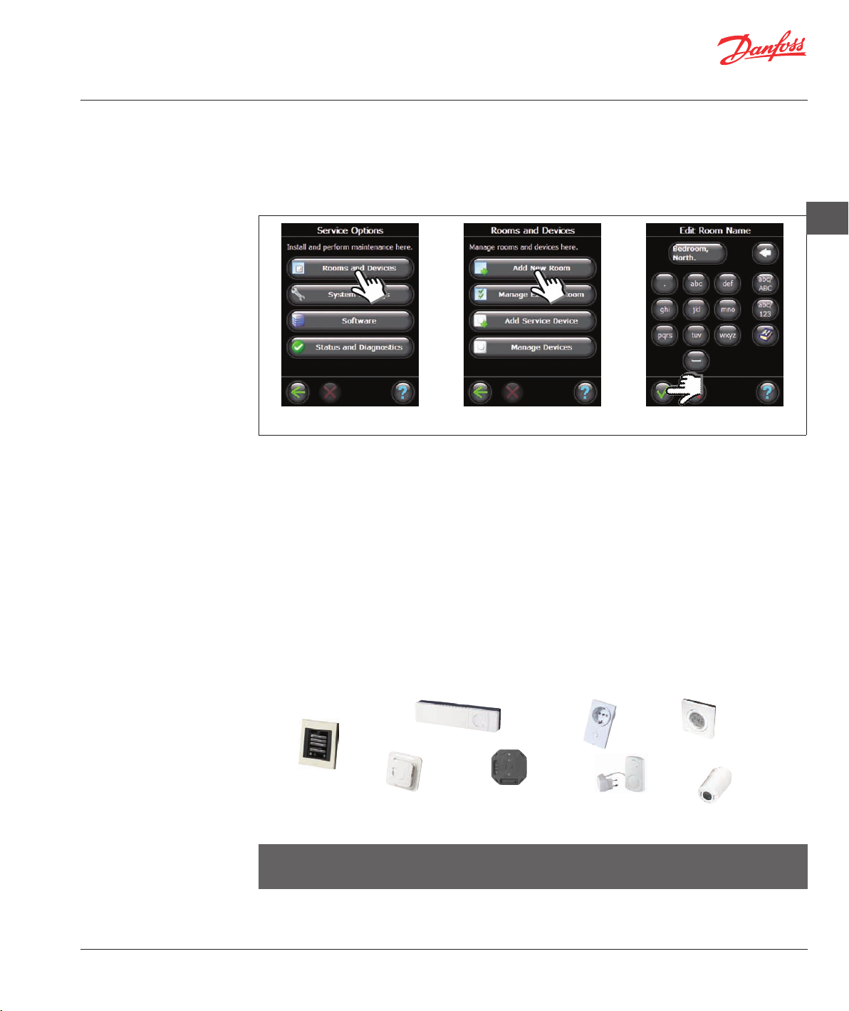
4: Create rooms
5: Purpose of adding
repeaters
Create all rooms in desired order before further configuration and adding of devices.
It is recommended to make a plan for the entire installation, which shows the individual placement and type
of all units in relation to room disposition. On this basis, the priority order and configuration of all devices
can be determined.
Remove the front cover and press the Set-Up pin for 3 seconds.
GB
1. Select Rooms and Devices. 2. Select Add New Room. 3. Enter/Edit Room Name.
When using a wireless transmission technology, several issues have to be taken in consideration, to ensure
the best performance:
• A maximum distance of 30 m between devices in free space must not be exceeded.
• Receiving devices should be placed on opposite or next wall as the transmitter.
• All metallic parts in the building construction can reduce communication signals.
• Reinforced concrete walls and floors dampen the signal strength significantly, but almost all types of
construction materials reduce the signal more or less.
• Also corners which is a result of the design of the building, can be a hinder for the further communication
of signals, due to either a longer distance or missing reflecting opportunities.
Many mains powered devices work automatically as repeaters without being installed as a dedicated
repeater - see manual.
If necessary, devices can be configured as service device to work as dedicated repeaters - see Configura-
tion 7: Adding service devices.
Example of repeating structure
Danfoss
Link™ CC
) ) ) ) ) ) ) ) )
Danfoss
Link™ HC
Danfoss
Link™ FT
) ) ) ) ) )
) ) ) ) ) ) ) ) ) ) ) ) )
Danfoss
Link™ HR
Danfoss
Link™ PR
) ) ) ) ) ) ) ) ) ) )
) ) ) ) ) ) ) ) ) ) ) ) )
) ) ) ) ) ) ) ) ) ) ) ) )
Danfoss
Link™ RU
) ) ) ) ) ) ) ) ) )
Danfoss
Link™ RS
Danfoss
connect
living
Max. 3 repeaters can be used between CC and the receiving device.
Note! Only devices with main power supply, and planned as repeaters (both normal and dedicated)
must always be configured first.
When devices are configured as repeaters, link test and network test is to be carried out to ensure the signal
quality.
VISGL45X © Danfoss 04/2011
7
Page 8
Installation Guide Danfoss Link™ CC - Configuration
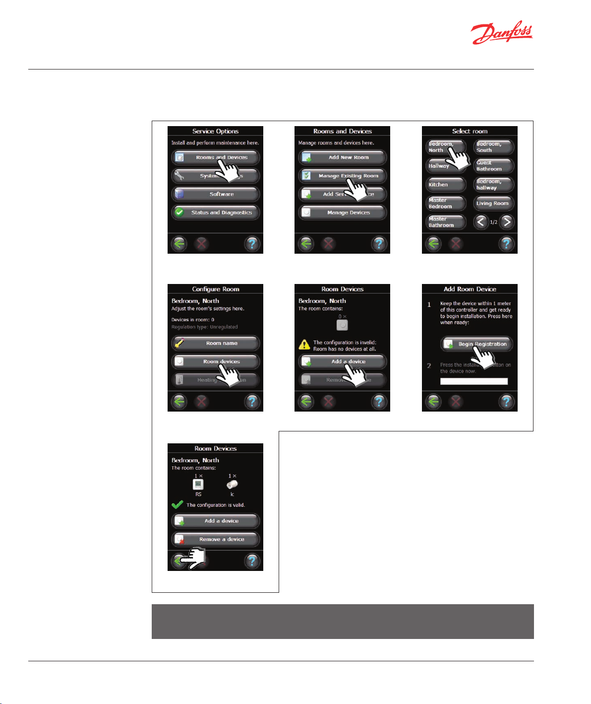
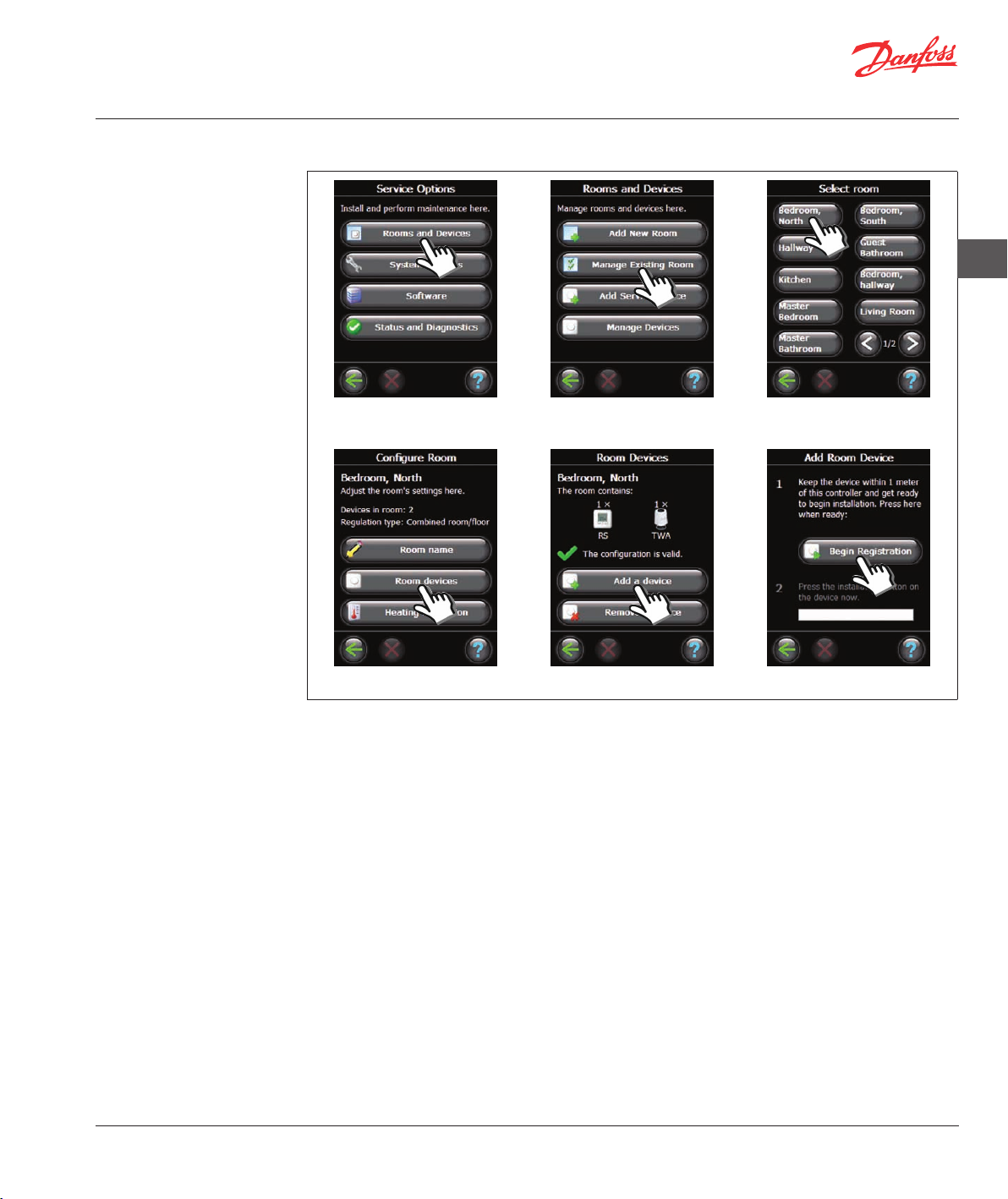
6: Adding room devices
All devices must be configured, according to the previous plan for the installation, to ensure the signal path.
Remove the front cover and press the Set-Up pin for 3 seconds.
1. Select Rooms and Devices. 2. Select Manage Existing Room. 3. Select a room..
4. Select Room devices. 5. Select Add a device. 6. Select Begin Registration.
When the first unit in relation to CC device is added, a link test must
be performed in order to ensured a successfully communication - see
manual for the individual device how this is done - but be sure that
CC is located on final destination before test is carried out.
Subsequently, the other repeaters must be added, before all remaining devices are being added.
When you have completed adding all devices for the individual room,
an overview of devices associated to the room will be showed.
Press back symbol to get to the Room Devices menu, where all associated room devices are listed.
7. Press Enter.
Note! Danfoss Link™ automatically selects the regulation principle according to the types of devices in
the room. To change regulation principle, see page 10.
8
VISGL45X © Danfoss 04/2011
Page 9
Installation Guide Danfoss Link™ CC - Configuration
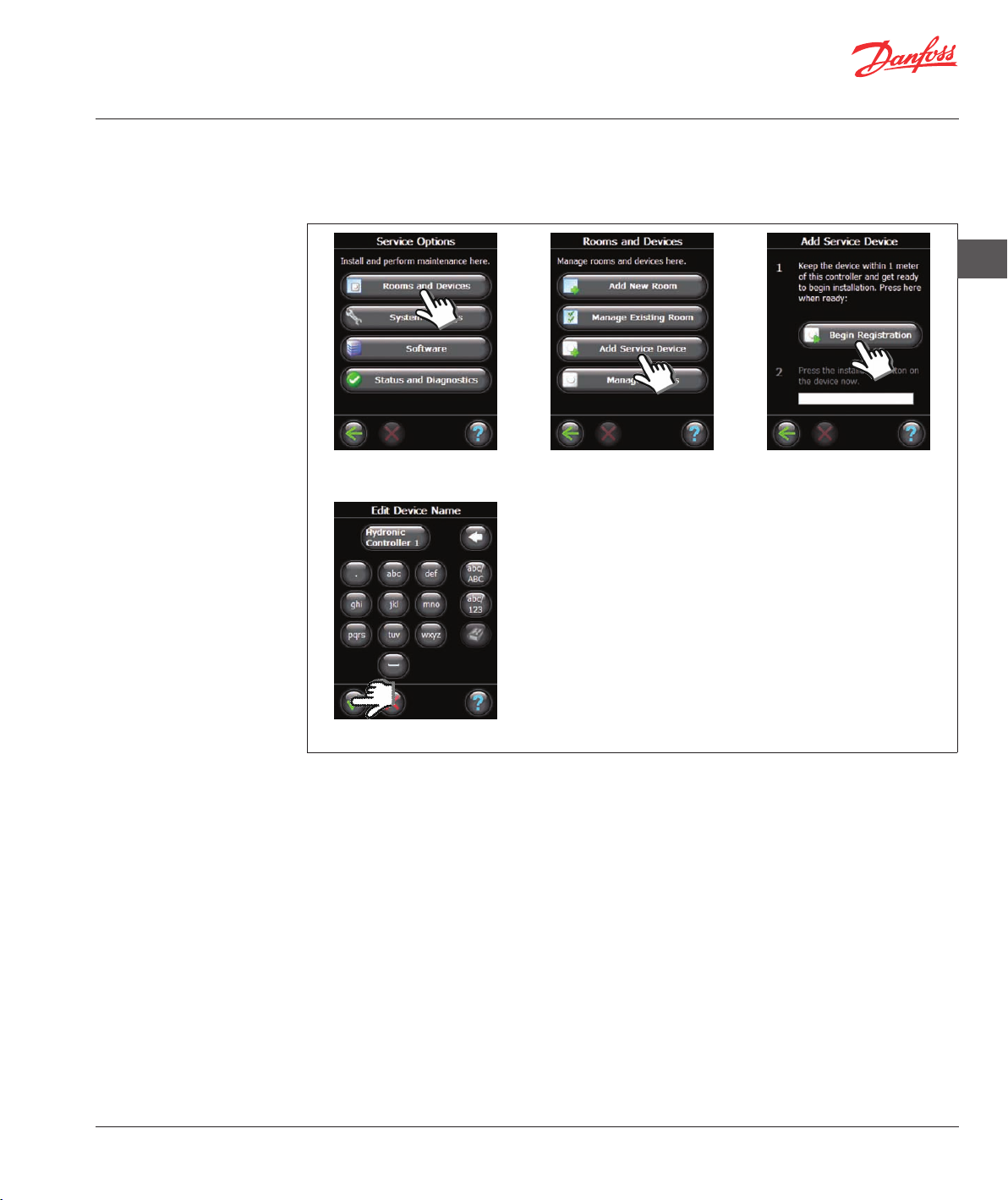
7: Adding service devices
Danfoss Link™ supports many different types of service devices with functions both like simple ON/OFF
devices for other electrically equipment, signal repeaters and controllers for hydronic systems.
Remove the front cover and press the Set-Up pin for 3 seconds.
GB
1. Select Rooms and Devices. 2. Select Add Service Device. 3. Select Begin Registration.
4. Enter/Edit Device Name.
VISGL45X © Danfoss 04/2011
9
Page 10
Installation Guide Danfoss Link™ CC - Configuration
8: Perform network test
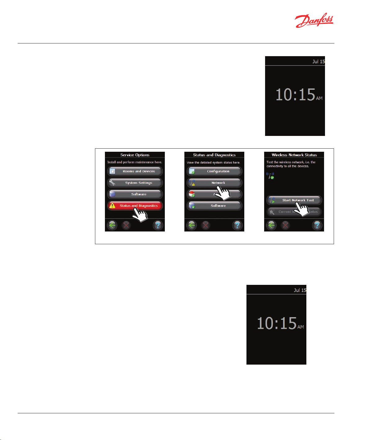
After finishing installation, a network test have to be performed, to
ensure, that communication between all added devices and Central
Controller is stable.
Do not perform the network test before CC is mounted at final destination.
Turn off the battery pack and place the Danfoss Link™ CC on the
previously installed mounting plate. The CC will now power up again
and show you a screen like this.If there is uncertainty about the
network’s performance, it is advisable to perform a network test before
the installation is completed entirely.
Remove the front cover and press the Set-Up pin for 3 seconds.
9: Finalise installation
1. Select Status and Diagnostics. 2. Select Network. 3. Select Start Network Test.
At the end of the network test the CC awaits for all battery operated devices to wake up and report.
To speed up the process to fulfil the network test, you may press any button on the battery operated
devices to force them to report immediately.
Press the Set-Up pin to close the installa tion.
10
VISGL45X © Danfoss 04/2011
Page 11
Installation Guide Danfoss Link™ CC - Modifying an existing installation
1: Adding devices to an
existing room
Remove the front cover and press the Set-Up pin for 3 seconds.
GB
1. Select Rooms and Devices. 2. Select Manage Existing Room. 3. Select an existing room.
4. Select Room Devices. 5. Select Add a Device. 6. Select Begin Registration.
Continue until all new devices are added to desired room.
Perform a network test each time the installation has been modified.
VISGL45X © Danfoss 04/2011
11
Page 12
Installation Guide Danfoss Link™ CC - Modifying an existing installation
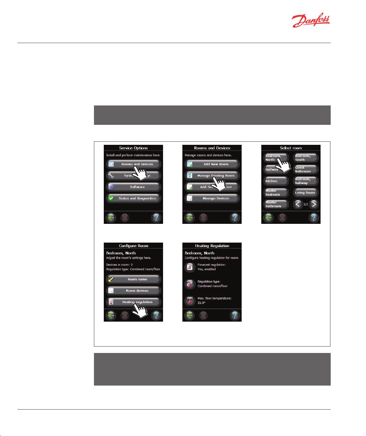
2: Changing parameters
for Heat Regulation
Danfoss recommends - especially by electrical heated floors - always to install a floor sensor.
• Comfort heating: Constant temperature on the floor in bathrooms and other rooms where a comfortable
warm surface is required.
• Total heating: Control of room temperature in living rooms etc. Install the floor sensor with the Danfoss
Link™ FT and a Danfoss Link™ RS. Choose Combined regulation when doing the configura tion on the
Danfoss Link™ CC.
Note! Alway use a floor sensor when the heating element is installed on or beneath wooden surfaces and
other surfaces sensitive to temperature !
Remove the front cover and press the Set-Up pin for 3 seconds.
1. Select Software. 2. Select Manage Existing Room. 3. Select an existing room.
• Forecasting method: by
activation of the forecast
method, the system will
automatically predict the
heating start-up time necessary
to reach desired room temperature at desired time.
• Regulation type: only in
connection with electrical
heating systems.
• Maximum floor temperature:
the default setting is 35°C.
4. Select Heating regulation. 5. Choose one of the settings (to
change a setting, please enter
the pin code 0044).
Note! The floor temperature is measured where the sensor is placed. The temperature at the floor sensor
can differ many degrees from the temperature measured on the top of e.g. a wooden floor. Floor manufactures often specif y the max. temperature on the top surface of the floor. Please contact your supplier
for information on maximum surface temperature.
12
VISGL45X © Danfoss 04/2011
Page 13
Installation Guide Danfoss Link™ CC - Modifying an existing installation
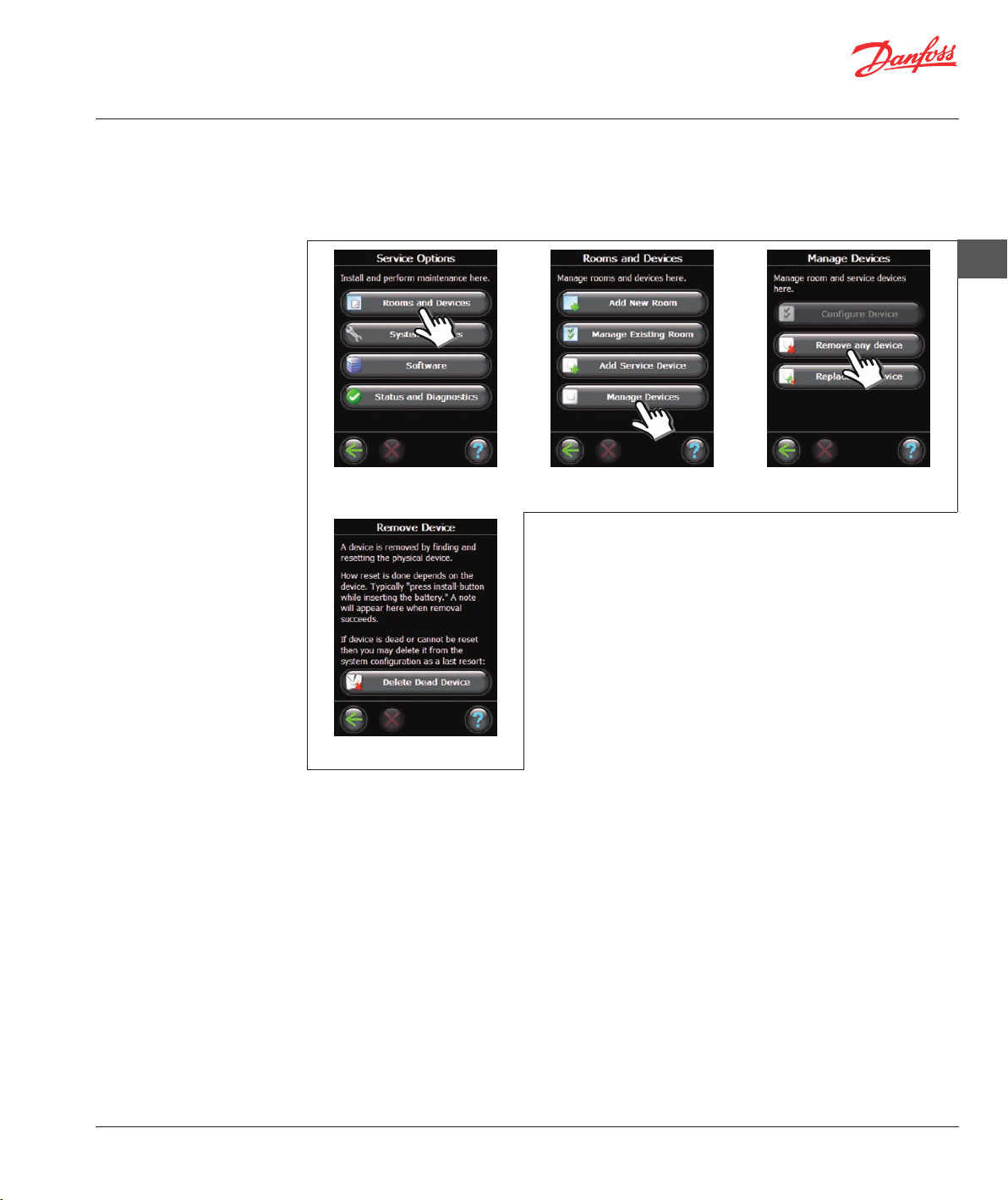
3: Removing / Resetting
a Room or a Service
device
Resetting a device
Any device can be reset, the procedure is individual for each device. See individual device manual.
Removing a device
Remove the front cover and press the Set-Up pin for 3 seconds.
GB
1. Select Rooms and Devices. 2. Select Manage Devices. 3. Select Remove any device.
If the device is to be replaced, remove the device from the system by
pressing Remove any device and then select the device to be
removed.
To add a replacement device just follow process described in
Modifying an existing installation 1: Adding devices to an existing
room (see page 9).
4: Factory reset of
Central Controller
4. Delete dead device.
Remove the front cover and press the reset button, at right side of the Central Controller, until clear Beep
sound can be heard.
VISGL45X © Danfoss 04/2011
13
Page 14
Installation Guide Danfoss Link™ CC - Upgrading software version
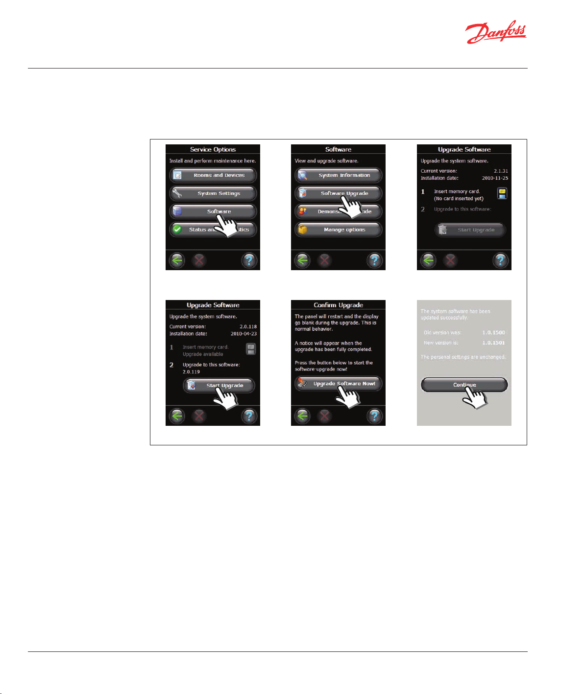
Upgrading
software version
Danfoss Link™ software is upgradable. New software versions is published for free download on
www. heating.danfoss.com.
Download the software upgrade to a SD Mini memory card.
Remove the front cover and press the Set-Up pin for 3 seconds.
1. Select Software. 2. Select Software Upgrade. 3. Insert memory card.
4. Select Start Upgrade. 5. Select Upgrade Software Now! 6. Select Continue.
TIP!
To avoid possible secession from the power supply, hold on top of Danfoss Link™ CC during insertion of the
memory card.
14
VISGL45X © Danfoss 04/2011
Page 15
Installation Guide Danfoss Link™ CC - Warnings
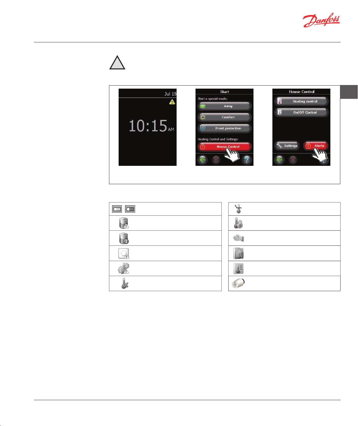
Warnings
If a warning or an alert occurs, a yellow alert icon will be shown on the Standby screen
- follow the procedure to find more information. will be shown on the Standby screen.
!
Remove the front cover and press the Set-Up pin for 3 seconds.
1. Alert icon on the Standby
screen.
Room Symbols
Installer tool battery warning Min. floor temperature limit
Battery level Critical on device Tamper proof / Restrictions enabled
2. Select House Control. 3. Select Alerts.
GB
Battery level low on device Manual operation
Device not responding Icon for Floor Temperature
Too many dead devices Icon for Room temperature
Heating turned off in a room Icon for TRV
VISGL45X © Danfoss 04/2011
15
Page 16
Installation Guide Danfoss Link™ CC - Technical specifications
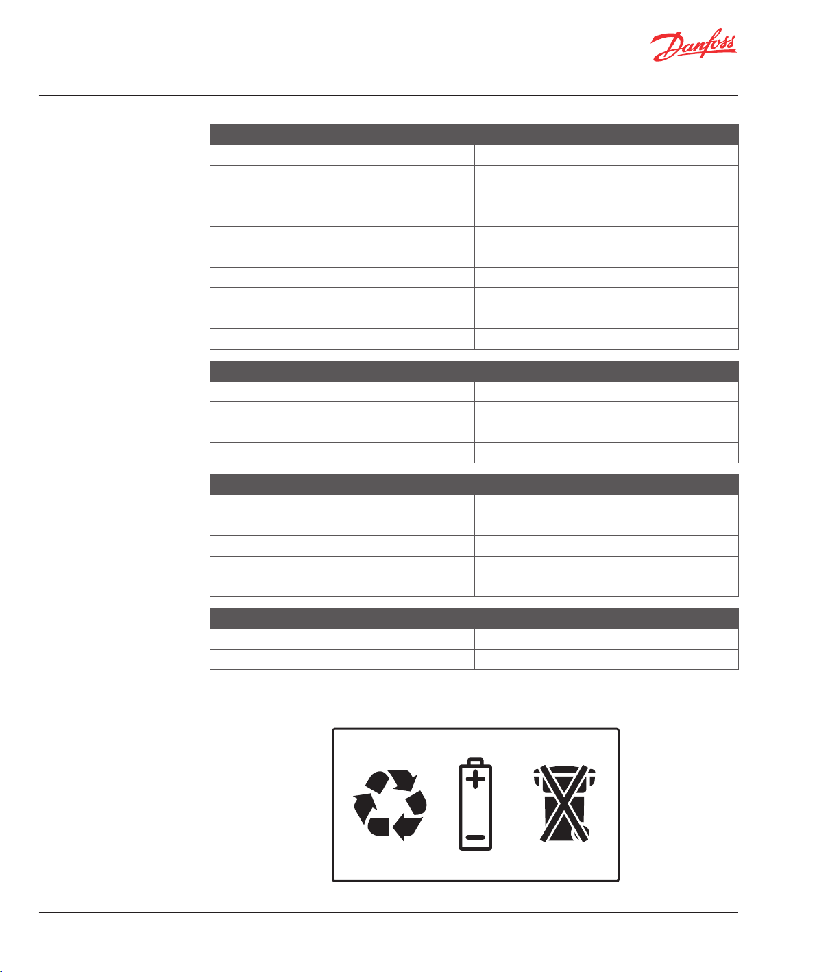
Technical specifications
Danfoss Link™ Central Controller
Operating voltage 15 VDC ±10%
Standby power consumption Max. 2W
Screen 3.5” TFT color w. touch
Ambient temperature -10 to +35°C
Transmission frequency 868.42MHz
Transmission range in normal buildings Up to 30m
Max. number of repeaters in a chain 3
Transmission power Max. 1 mW
IP class 21
Dimensions 125 mm x 107 mm x 25 mm
Danfoss Link™ PSU (In-Wall)
Operation Voltage 100-250 VAC 50/60Hz
Output Voltage 15 VDC ±10%
Standby power consumption Max. 0.15W
Max. load 10W
Danfoss Link™ NSU (Net Adapter)
Operation Voltage 100-240 VAC 50/60Hz
Output Voltage 15 VDC ±10%
Standby power consumption Max. 0.75W
Cable length. 2.5m
Max load 10W
Disposal instructions
16
Danfoss Link™ BSU (Battery Supply Unit)
Output Voltage 15 VDC ±10%
Number of batteries 10 x AA
VISGL45X © Danfoss 04/2011
Page 17
Installationsanleitung Danfoss Link™ CC – Einführung
Stichwortverzeichnis
Einführung
Installation
Konfiguration
1: Hinzufügen von Geräten zu dem System . . . . . . . . . . . . . . . . . . . . . . . . . . . . . . . . . . . . . . . . . . . . . . . . . . . . . . . . . . 19
2: Einstellen von Land, Sprache und Datum/Uhrzeit. . . . . . . . . . . . . . . . . . . . . . . . . . . . . . . . . . . . . . . . . . . . . . . . . . 19
3: Start des Installationsmenüs . . . . . . . . . . . . . . . . . . . . . . . . . . . . . . . . . . . . . . . . . . . . . . . . . . . . . . . . . . . . . . . . . . . . . . 19
4: Erstellen von Räumen. . . . . . . . . . . . . . . . . . . . . . . . . . . . . . . . . . . . . . . . . . . . . . . . . . . . . . . . . . . . . . . . . . . . . . . . . . . . . 20
5: Einsatz von Verstärkern . . . . . . . . . . . . . . . . . . . . . . . . . . . . . . . . . . . . . . . . . . . . . . . . . . . . . . . . . . . . . . . . . . . . . . . . . . .20
6: Hinzufügen von Geräten. . . . . . . . . . . . . . . . . . . . . . . . . . . . . . . . . . . . . . . . . . . . . . . . . . . . . . . . . . . . . . . . . . . . . . . . . . 21
7: Hinzufügen von Wartungsgeräten . . . . . . . . . . . . . . . . . . . . . . . . . . . . . . . . . . . . . . . . . . . . . . . . . . . . . . . . . . . . . . . .22
8: Durchführen eines Netzwerktests . . . . . . . . . . . . . . . . . . . . . . . . . . . . . . . . . . . . . . . . . . . . . . . . . . . . . . . . . . . . . . . . .23
9: Abschließen der Installation . . . . . . . . . . . . . . . . . . . . . . . . . . . . . . . . . . . . . . . . . . . . . . . . . . . . . . . . . . . . . . . . . . . . . .23
Ändern einer vorhandenen Installation
1: Hinzufügen von Geräten zu einem vorhandenen Raum. . . . . . . . . . . . . . . . . . . . . . . . . . . . . . . . . . . . . . . . . . . . 24
2: Ändern der Parameter für die Heizungsregelung . . . . . . . . . . . . . . . . . . . . . . . . . . . . . . . . . . . . . . . . . . . . . . . . . .25
3: Entfernen/Rücksetzen eines Geräts . . . . . . . . . . . . . . . . . . . . . . . . . . . . . . . . . . . . . . . . . . . . . . . . . . . . . . . . . . . . . . . 26
4: Rücksetzen des Zentralreglers auf die Werkseinstellungen. . . . . . . . . . . . . . . . . . . . . . . . . . . . . . . . . . . . . . . . .26
Aktualisieren der Softwareversion
Warnmeldungen . . . . . . . . . . . . . . . . . . . . . . . . . . . . . . . . . . . . . . . . . . . . . . . . . . . . . . . . . . . . . . . . . . . . . . . . . . . . . . . . . . . . . . . 28
Technische Spezifikationen
Hinweise zur Entsorgung
. . . . . . . . . . . . . . . . . . . . . . . . . . . . . . . . . . . . . . . . . . . . . . . . . . . . . . . . . . . . . . . . . . . . . . . . . . . . . . . . . . . . . . . . . . . . . 17
. . . . . . . . . . . . . . . . . . . . . . . . . . . . . . . . . . . . . . . . . . . . . . . . . . . . . . . . . . . . . . . . . . . . . . . . . . . . . . . . . . . . . . . . . . . . . 18
. . . . . . . . . . . . . . . . . . . . . . . . . . . . . . . . . . . . . . . . . . . . . . . . . . . . . . . . . . . . . . . . . . . . . . 27
. . . . . . . . . . . . . . . . . . . . . . . . . . . . . . . . . . . . . . . . . . . . . . . . . . . . . . . . . . . . . . . . . . . . . . . . . . . . .29
. . . . . . . . . . . . . . . . . . . . . . . . . . . . . . . . . . . . . . . . . . . . . . . . . . . . . . . . . . . . . . . . . . . . . . . . . . . . . . .30
DE
Einführung
Danfoss Link™ ist ein drahtloses Regelungssystem für
verschiedene Heizungssysteme.
Die zentrale Regelungseinheit ist der Danfoss Link™
CC (Central Controller, Zentralregler), der mit einem
Farb-Touchscreen ausgestattet ist. Über diesen
Touchscreen erfolgen die Steuerung und Regelung
der gesamten Installation.
Der Danfoss Link™ CC kommuniziert per Funk mit
den weiteren Link-Komponenten in der Installation.
VISGL45X © Danfoss 04/2011
17
Page 18
Installationsanleitung Danfoss Link™ CC – Installation
Installation
Der Übertragungsbereich des Funksystems Danfoss
Link™ ist für die meisten Anwendungen ausreichend.
Allerdings verfügt jedes Gebäude über andere Hindernisse, die die Kommunikation und den maximalen Übertragungsbereich beeinträchtigen.
Bei Kommunikationsproblemen empfiehlt Danfoss
den Einsatz von Zubehörteilen wie beispielsweise
Verstärkern. In Ausnahmefällen ist das Funksystem
für Ihre Installation möglicherweise nicht geeignet.
Hinweis! Den Devilink™ CC erst dann einschalten, wenn dies im Handbuch gefordert wird.
Nicht die Schutzfolie auf dem Touchscreen abziehen. Dies ist Aufgabe des Endanwenders.
Der Danfoss Link™ CC kann mit einem Unterputz(PSU) oder Aufputznetzteil (NSU) montiert werden.
Montage des Danfoss Link™ CC mit einem Unterputznetzteil:
• Das PSU über den Wandkasten halten und die vier
Schraublöcher markieren.
Die Oberseite muss eben ausgerichtet sein.
• Die vier Löcher bohren und Dübel einsetzen.
• Das PSU gemäß dem Anschlussplan auf der Rückseite anschließen.
• Das PSU mit den vier Schrauben befestigen.
Bei der Montage des Danfoss Link™ CC ist auf Folgendes zu achten:
Den Danfoss Link™ CC nicht
in Bereichen mit direkter
Sonneneinstrahlung montieren.
Das Gerät sollte in einer Höhe von 140170 cm montiert werden.
Unterputznetzteil (PSU) für Danfoss Link™
Montage des Danfoss Link™ CC mit einem Aufputznetzteil:
• Die Befestigungsplatte an die Wand halten die die
vier Schraubenlöcher markieren. Die Oberseite
muss eben ausgerichtet sein.
• Die vier Löcher bohren und Dübel einsetzen.
• Die Befestigungsplatte mit den vier Schrauben
fixieren.
Den Danfoss Link™ CC noch nicht montieren!
• Das Aufputznetzteil an eine Steckdose anschließen.
18
VISGL45X © Danfoss 04/2011
Aufputznetzteil (NSU) für Danfoss Link™
Page 19
Installationsanleitung Danfoss Link™ CC – Konfiguration
1: Hinzufügen von
Geräten zu dem
System
2: Einstellen von Land,
Sprache und Datum/
Uhrzeit
Hinweis! Den Danfoss Link™ CC erst dann konfigurieren, wenn alle Raumgeräte montiert wurden.
Beim Hinzufügen von Geräten zu dem Danfoss-LinkSystem ist darauf zu achten, dass der Abstand
zwischen Zentralregler und Gerät nicht mehr als
1,5 M beträgt. Dafür ist eine Batterieeinheit (BSU)
für Danfoss Link verfügbar.
Die Batterieabdeckung beiseite schieben und
10 neue AA-Alkalibatterien in die Batterieeinheit
einsetzen.
Dabei auf die richtige Polarität achten.
Die Batterieabdeckung wieder aufschieben und die
Batterieeinheit an der Rückseite des Danfoss Link™
CC befestigen. Zur Inbetriebnahme den Schalter auf
der Batterieeinheit in die Stellung ON bringen.
Der Danfoss Link™ CC startet. Dies kann einige
Minuten dauern.
DE
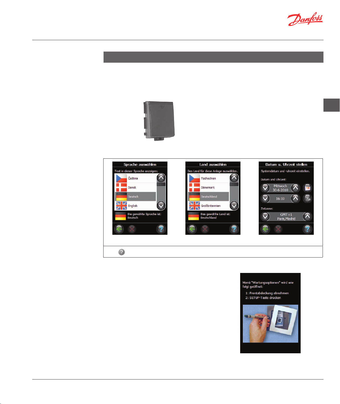
3: Start des Installations-
menüs
1. Sprache auswählen. 2. Land auswählen. 3. Datum u. Uhrzeit einstellen.
Wenn
Die Frontabdeckung des Danfoss Link™ CC vorsichtig abziehen. Den SETUP-Stift drei Sekunden lang
eindrücken, um das Installationsmenü zu starten.
Die Regelung angeschlossener Geräte über Danfoss
Link erfolgt in zwei unterschiedlichen Modi:
1. Heizungsregelung: Regelung der Raumheizgeräte
2. EIN/AUS-Funktionen: Geplante EIN/AUS-Regelung
aufleuchtet, ist ein Hilfetext mit einer Beschreibung des aktuellen Vorgangs verfügbar.
– für weitere Informationen siehe Konfiguration
4: Räume erstellen.
verschiedener Elektrogeräte – für weitere Informationen siehe Konfiguration 7: Hinzufügen
von Wartungsgeräten.
VISGL45X © Danfoss 04/2011
19
Page 20
Installationsanleitung Danfoss Link™ CC – Konfiguration
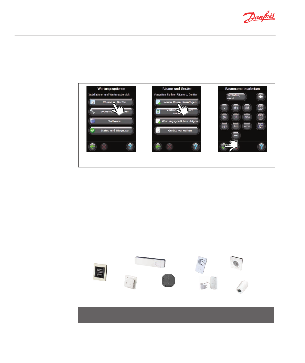
4: Erstellen von Räumen
5: Einsatz von Verstärkern
Erstellen vor der weiteren Konfiguration und dem Hinzufügen von Geräten alle Räume in der gewünschten
Reihenfolge.
Es wird empfohlen, einen Plan der gesamten Installation zu erstellen, aus dem die jeweilige Position und der
Typ sämtlicher Einheiten im Verhältnis zur Raumeinrichtung hervorgeht. Auf dieser Grundlage können die
Priorität und die Konfiguration aller Geräte bestimmt werden.
Frontabdeckung abnehmen und den SETUP-Stift drei Sekunden lang eindrücken.
1. „Räume u. Geräte“ auswählen. 2. „Neuen Raum hinzufügen“
auswählen.
3. Raumname eingeben/
bearbeiten.
Im Falle einer Funkübertragung sind im Sinne einer optimalen Leistung verschiedene Aspekte zu berücksichtigen.
• Der maximal zulässige Abstand zwischen den einzelnen Geräten im freien Raum beträgt 30 m.
• Die Empfängergeräte sind vom Sender aus an der gegenüberliegenden oder nächsten Wand zu platzieren.
• Durch Metallteile in der Gebäudestruktur können die Kommunikationssignale beeinträchtigt werden.
• Durch Stahlbetonwände und -böden wird die Signalstärke erheblich gedämpft (dies gilt jedoch mehr oder
weniger für sämtliche Baustoffe).
• Auch baubedingte Eckbereiche können die weitere Signalübertragung aufgrund einer längeren Distanz
oder fehlender Reflektionsmöglichkeiten behindern.
20
Viele netzgespeiste Geräte funktionieren automatisch als Verstärker, obwohl sie nicht zu diesem Zweck
angeschlossen wurden (siehe Handbuch). Bei Bedarf können Geräte als Wartungsgeräte mit spezieller
Verstärkerfunktion konfiguriert werden - siehe Konfiguration 7: Hinzufügen von Wartungsgeräten.
Beispiel für eine Verstärkungsstruktur
Danfoss
Link™ CC
) ) ) ) ) ) ) ) )
Danfoss
Link™ HC
Danfoss
Link™ FT
) ) ) ) ) )
) ) ) ) ) ) ) ) ) ) ) ) )
Danfoss
Link™ HR
Danfoss
Link™ PR
) ) ) ) ) ) ) ) ) ) )
) ) ) ) ) ) ) ) ) ) ) ) )
) ) ) ) ) ) ) ) ) ) ) ) )
Danfoss
Link™ RU
) ) ) ) ) ) ) ) ) )
Danfoss
Link™ RS
Danfoss
connect
living
Zwischen Zentralregler und Empfänger können maximal drei Verstärker eingesetzt werden.
Hinweis! Geräte mit Netzanschluss und als Verstärker geplante Geräte (normal und speziell) müssen
stets zuerst konfiguriert werden.
Wenn Geräte als Verstärker konfiguriert sind, werden zur Überprüfung der Signalqualität ein Verbindungsund ein Netzwerktest durchgeführt.
VISGL45X © Danfoss 04/2011
Page 21
Installationsanleitung Danfoss Link™ CC – Konfiguration
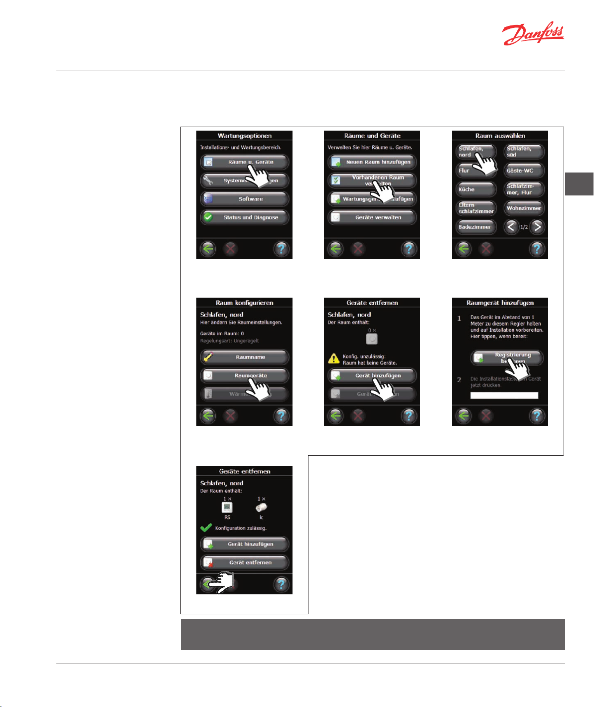
6: Hinzufügen von
Raumgeräten
Im Sinne eines ordnungsgemäßen Signalwegs müssen alle Geräte in Übereinstimmung mit dem Installationsplan konfiguriert werden.
Frontabdeckung abnehmen und den SETUP-Stift drei Sekunden lang eindrücken.
1. „Räume u. Geräte“ auswählen. 2. „Vorhandenen Raum verwalten“
auswählen.
3. Raum auswählen.
DE
4. „Raumgeräte“ auswählen. 5. „Gerät hinzufügen“ auswählen. 6. „Registrierung beginnen“
auswählen.
Beim Hinzufügen des ersten Geräts im Verhältnis zum Zentralregler
muss zur Sicherstellung einer fehlerfreien Kommunikation ein
Verbindungstest durchgeführt werden (siehe Handbuch des entsprechenden Geräts). Vor diesem Test ist darauf zu achten, dass sich der
Zentralregler an seiner endgültigen Position befindet.
Im Anschluss sind zunächst die weiteren Verstärker und dann erst alle
restlichen Geräte hinzuzufügen.
Wenn alle Geräte für einen bestimmten Raum hinzugefügt wurden,
erscheint eine Übersicht der dem Raum zugeordneten Geräte.
Auf das Zurück-Symbol klicken, um das Menü „Raumgeräte“ aufzurufen. In diesem Menü sind alle zugeordneten Raumgeräte aufgeführt.
7. Mit „Enter“ bestätigen.
Hinweis! Danfoss Link™ wählt das Regelungsprinzip automatisch in Abhängigkeit der Gerätetypen in
dem Raum aus. Zur Änderung des Regelungsprinzips siehe Seite 23.
VISGL45X © Danfoss 04/2011
21
Page 22
Installationsanleitung Danfoss Link™ CC – Konfiguration
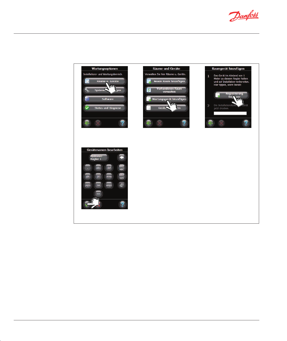
7: Hinzufügen von
Wartungsgeräten
Danfoss Link™ unterstützt zahlreiche Wartungsgerätetypen mit einfachen EIN/AUS-Funktionen für andere
Elektrogeräte, Signalverstärkerfunktionen und Reglerfunktionen für Hydraulische Systeme.
Frontabdeckung abnehmen und den SETUP-Stift drei Sekunden lang eindrücken.
1. „Räume u. Geräte“ auswählen. 2. „Wartungsgerät hinzufügen“
auswählen.
3. „Registrierung beginnen“
auswählen.
22
4. Gerätename eingeben/
bearbeiten.
VISGL45X © Danfoss 04/2011
Page 23
Installationsanleitung Danfoss Link™ CC – Konfiguration
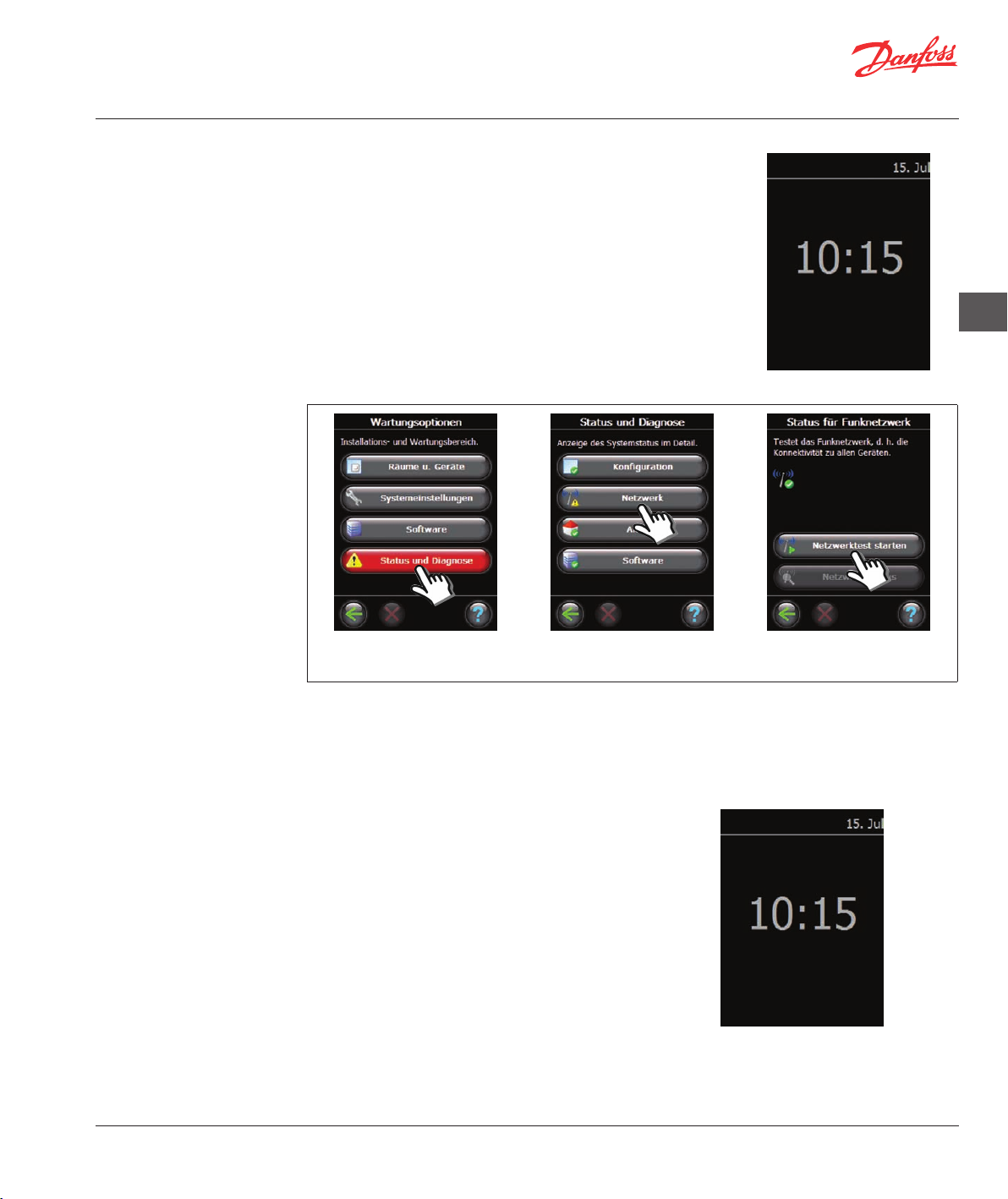
8: Durchführen eines
Netzwerktests
Nach Abschluss der Installation muss ein Netzwerktest durchgeführt
werden, um die stabile Kommunikation zwischen dem Zentralregler und
sämtlichen hinzugefügten Geräten zu überprüfen.
Den Netzwerktest erst dann durchführen, wenn der Zentralregler an
seiner endgültigen Position montiert ist.
Die Batterieeinheit ausschalten und den Danfoss Link™ CC auf die zuvor
montierte Befestigungsplatte setzen. Der Zentralregler schaltet wieder
ein und zeigt folgenden Bildschirm an.
Bei Zweifeln hinsichtlich der Netzwerkleistung sollte vor Abschluss der
Installation ein Netzwerktest durchgeführt werden.
Frontabdeckung abnehmen und den SETUP-Stift drei Sekunden lang eindrücken.
DE
9: Abschließen
der Installation
1. „Status und Diagnose“
auswählen.
Zum Abschluss des Netzwerktests wartet der Zentralregler auf die Einschaltung und Berichterstattung sämtlicher batteriebetriebener Geräte.
Um dies zu beschleunigen und den Netzwerktest abzuschließen, können Sie eine beliebige Taste an den
batteriebetriebenen Geräten drücken und diese so zu einer sofortigen Berichterstattung zwingen.
Den SETUP-Stift eindrücken, um die Installation zu
beenden.
2. „Netzwerk“ auswählen. 3. „Netzwerktest starten“
auswählen.
VISGL45X © Danfoss 04/2011
23
Page 24
Installationsanleitung Danfoss Link™ CC - Ändern einer vorhandenen Installation
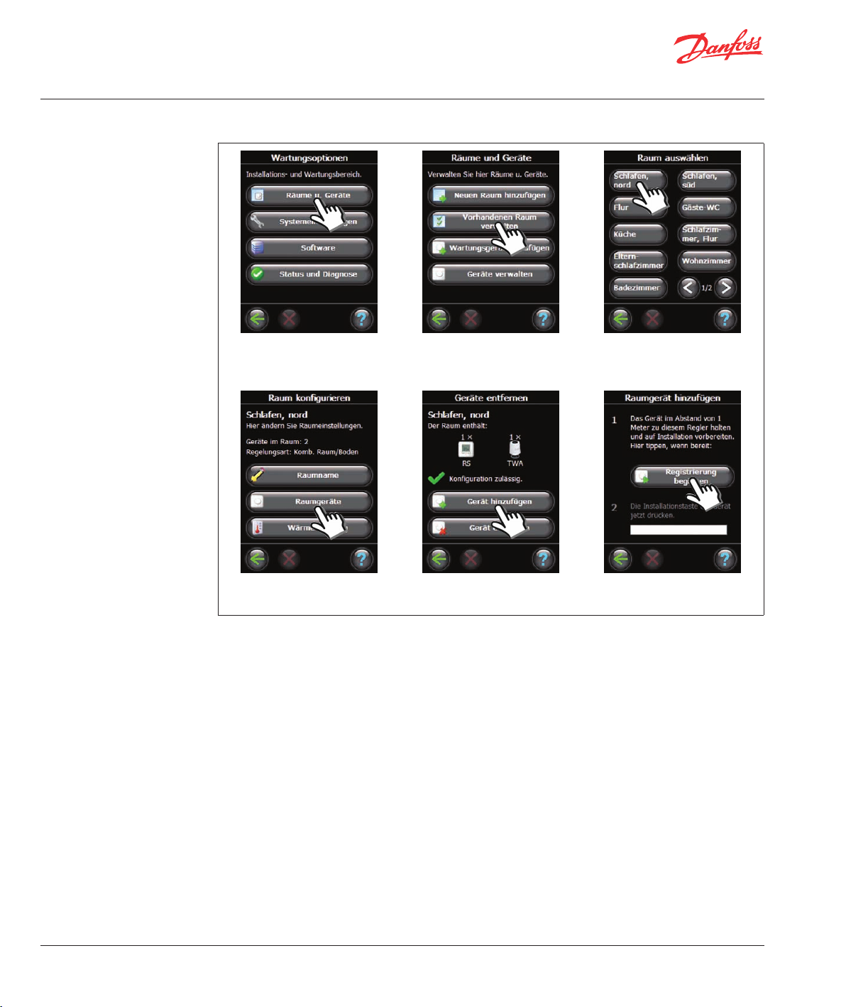
1: Hinzufügen von
Geräten zu einem
vorhandenen Raum
Frontabdeckung abnehmen und den SETUP-Stift drei Sekunden lang eindrücken.
1. „Räume u. Geräte“ auswählen. 2. „Vorhandenen Raum verwalten“ auswählen.
3. Einen vorhandenen Raum
auswählen.
24
4. „Raumgeräte“ auswählen. 5. „Gerät hinzufügen“ auswählen. 6. „Registrierung beginnen“
auswählen.
Fortfahren, bis dem gewünschten Raum alle neuen Geräte hinzugefügt wurden.
Nach jeder Änderung der Installation einen Netzwerktest durchführen.
VISGL45X © Danfoss 04/2011
Page 25
Installationsanleitung Danfoss Link™ CC - Ändern einer vorhandenen Installation
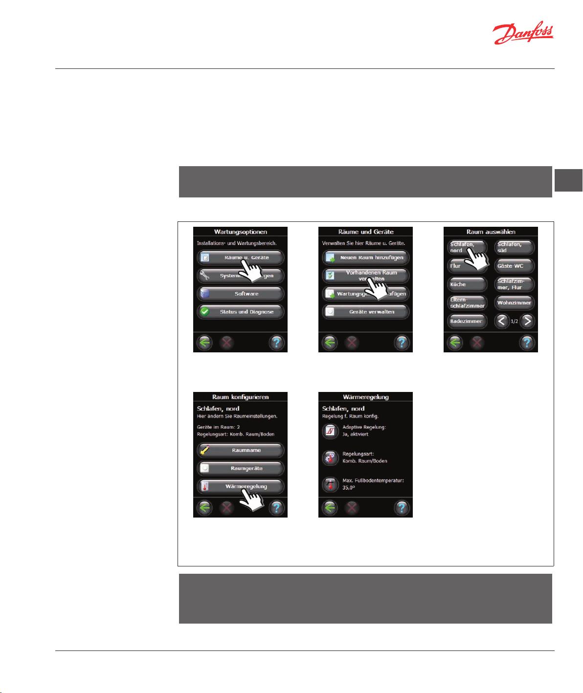
2: Ändern der Parameter
für die Heizungsregelung
Danfoss empfiehlt (insbesondere bei elektrischen Fußbodenheizungen) stets die Installation eines
Bodensensors.
• Komfortheizung: Konstante Bodentemperatur in Badezimmern und weiteren Räumen, in denen eine
angenehm warme Bodenfläche gewünscht ist.
• Gesamtheizung: Raumtemperaturregelung in Wohnzimmern usw. Den Bodensensor mit dem Danfoss
Link™ FT und einem Danfoss Link™ RS installieren. Im Rahmen der Konfiguration des Danfoss Link™ CC
eine kombinierte Regelung einstellen.
Hinweis! Wenn das Heizelement auf oder unter Holzflächen oder anderen temperaturempfindlichen
Flächen installiert wird, muss in jedem Fall ein Bodensensor installiert werden.
Frontabdeckung abnehmen und den SETUP-Stift drei Sekunden lang eindrücken.
1. „Räume u. Geräte“ auswählen. 2. „Vorhandenen Raum verwalten“ auswählen.
3. Einen vorhandenen Raum
auswählen.
DE
• Adaptive Regelung: Durch
Aktivierung der adaptiven
Regelung prognostiziert das
System automatisch die
erforderliche Einschaltzeit der
Heizung, um zu dem gewünschten Zeitpunkt die gewünschte
Raumtemperatur zu erreichen.
• Regelungsart: Nur bei
Elektroheizungen.
• Max. Fußbodentemperatur:
Die Standardeinstellung lautet
35 °C.
4. „Wärmeregelung“ auswählen. 5. Eine der Einstellungen
Hinweis! Die Bodentemperatur wird dort gemessen wo der Bodensensor installiert ist. Die Temperatur
am Bodensensor kann deutlich von der beispielsweise an der Oberseite eines Holzbodens gemessenen
Temperatur abweichen. Bodenhersteller geben häufig die Höchsttemperatur an der Bodenoberfläche
an. Informationen zur maximalen Oberflächentemperatur erhalten Sie von Ihrem Lieferanten.
VISGL45X © Danfoss 04/2011
auswählen (zum Ändern einer
Einstellung den PIN-Code 0044
eingeben).
25
Page 26
Installationsanleitung Danfoss Link™ CC - Ändern einer vorhandenen Installation
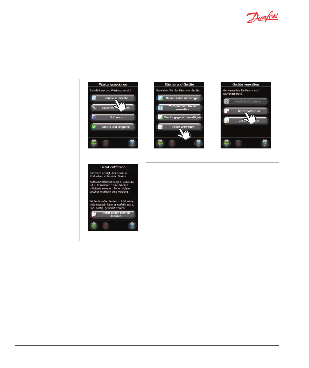
3: Entfernen/Rücksetzen
eines Raum- oder
Wartungsgeräts
Rücksetzen eines Geräts
Jedes Gerät kann zurückgesetzt werden. Das Rücksetzverfahren variiert je nach Gerät, siehe entsprechendes Handbuch.
Entfernen eines Geräts
Frontabdeckung abnehmen und den SETUP-Stift drei Sekunden lang eindrücken.
1. Välj ”Rum och enheter”. 2. Välj ”Hantera enheter”. 3. „Gerät entfernen“ auswählen.
Wenn das Gerät ausgetauscht werden soll, auf die Schaltfläche „Gerät
entfernen“ klicken und das aus dem System zu entfernende Gerät
auswählen.
Zum Hinzufügen eines Austauschgeräts einfach die unter Ändern
einer vorhandenen Installation 1: Hinzufügen von Geräten zu
einem vorhandenen Raum (siehe Seite 24) beschriebenen Schritte
befolgen.
4: Rücksetzen des
Zentralreglers auf die
Werkseinstellungen
26
4. Gerät außer Betrieb löschen.
Frontabdeckung abnehmen und die Reset-Taste an der rechten Seite des Zentralreglers drücken, bis
ein deutlichen Piepgeräusch ertönt.
VISGL45X © Danfoss 04/2011
Page 27
Installationsanleitung Danfoss Link™ CC – Aktualisieren der Softwareversion
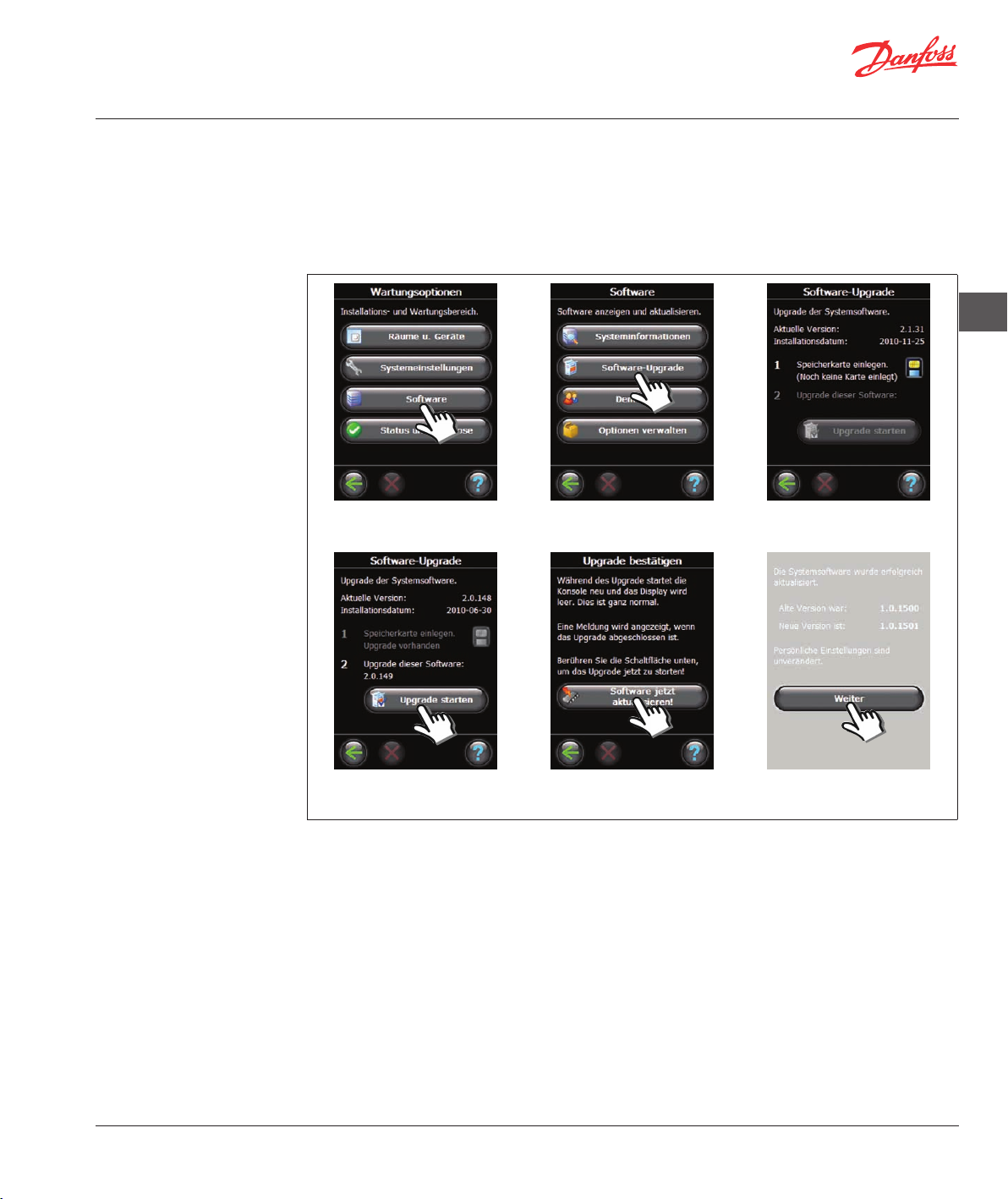
Aktualisieren
der Softwareversion
Die Danfoss Link™-Software kann aktualisiert werden. Neue Softwareversionen stehen unter folgendem
Link kostenlos zum Download bereit:
www. heating.danfoss.com.
Speichern Sie die Softwareaktualisierung auf eine SD-Mini-Speicherkarte.
Frontabdeckung abnehmen und den SETUP-Stift drei Sekunden lang eindrücken.
DE
1. „Software“ auswählen. 2. „Software Upgrade“ auswählen. 3. Speicherkarte einsetzen.
4. „Upgrade starten“ auswählen. 5. „Software jetzt aktualisieren!“
auswählen.
TIPP
Um eine mögliche Trennung von der Stromversorgung zu vermeiden, beim Einsetzen der Speicherkarte auf die
Oberseite des Danfoss Link™ CC drücken.
VISGL45X © Danfoss 04/2011
6. „Weiter“ auswählen.
27
Page 28
Installationsanleitung Danfoss Link™ CC – Warnmeldungen und FAQ
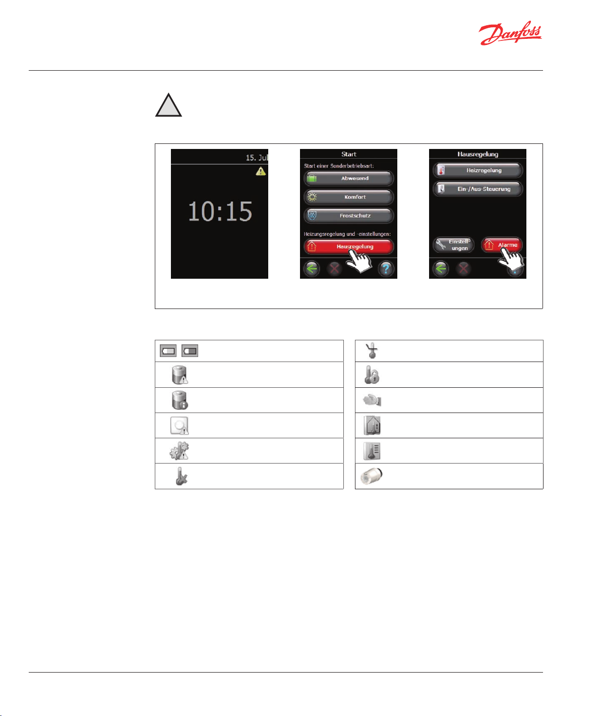
Warnmeldungen
Im Falle einer Warnung oder eines Alarms wird auf dem Standby-Bildschirm ein gelbes Alarmsymbol angezeigt.
!
- Befolgen Sie das Verfahren für weitere Informationen.
Frontabdeckung abnehmen und den SETUP-Stift drei Sekunden lang eindrücken.
1. Alarmsymbol auf dem
Standby-Bildschirm.
Raumsymbole
Batteriewarnung Installationstool Grenzwert min. Bodentemperatur
Kritischer Batterieladestand in Gerät
2. „Hausregelung“ auswählen. 3. „Alarme“ auswählen.
Manipulationssicher/Einschränkungen
aktiviert
28
Niedriger Batterieladestand in Gerät Handbetrieb
Gerät reagiert nicht Symbol für Bodentemperatur
Zu viele inaktive Geräte Symbol für Raumtemperatur
Heizung in einem Raum ausgeschaltet Symbol für Heizkörperthermostat
VISGL45X © Danfoss 04/2011
Page 29
Installationsanleitung Danfoss Link™ CC – Technische Spezifikationen
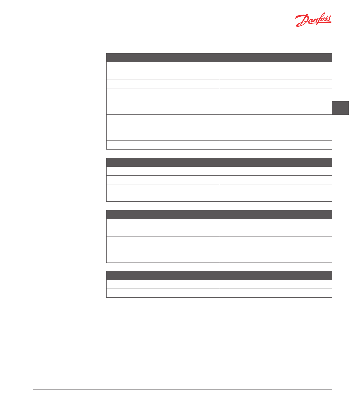
Technische
Spezifikationen
Zentralregler Danfoss Link™
Betriebsspannung 15 VDC ±10 %
Leistungsaufnahme im Standby-Betrieb Max. 2 W
Bildschirm TFT-Farbdisplay (3,5”) mit Touchscreen
Umgebungstemperatur
Übertragungsfrequenz 868,42 MHz
Übertragungsbereich in normalen Gebäuden
Max. Anzahl Verstärker in einer Kette 3
Übertragungsleistung Max. 1 mW
IP-Schutzart 21
Abmessungen 125 mm x 107 mm x 25 mm
Danfoss Link™ PSU (Unterputznetzteil)
Betriebsspannung 100-250 VAC 50/60 Hz
Ausgangsspannung 15 VDC ±10 %
Leistungsaufnahme im Standby-Betrieb Max. 0,15 W
Max. Belastung
Danfoss Link™ NSU (Netzadapter)
Betriebsspannung 100-240 VAC 50/60 Hz
Ausgangsspannung 15 VDC ±10 %
Leistungsaufnahme im Standby-Betrieb Max. 0,75 W
Kabellänge
Max. Belastung 10 W
-10 bis +35 °C
Bis 30 m
10 W
2,5 m
DE
Danfoss Link™ BSU (Batterieeinheit)
Ausgangsspannung 15 VDC ±10 %
Anzahl der Batterien 10 x AA
VISGL45X © Danfoss 04/2011
29
Page 30
Installationsanleitung Danfoss Link™ CC – Hinweise zur Entsorgung
Hinweise zur Entsorgung
30
VISGL45X © Danfoss 04/2011
Page 31

Guide d’installation Danfoss Link™ CC - Introduction
Sommaire
Introduction
Installation
Configuration
1 : Ajout d’unités locales dans le système . . . . . . . . . . . . . . . . . . . . . . . . . . . . . . . . . . . . . . . . . . . . . . . . . . . . . . . . . . . . 33
2 : Réglage du pays, de la langue et des date/heure . . . . . . . . . . . . . . . . . . . . . . . . . . . . . . . . . . . . . . . . . . . . . . . . . .33
3 : Démarrage du menu d’installation . . . . . . . . . . . . . . . . . . . . . . . . . . . . . . . . . . . . . . . . . . . . . . . . . . . . . . . . . . . . . . .33
4 : Création de pièces . . . . . . . . . . . . . . . . . . . . . . . . . . . . . . . . . . . . . . . . . . . . . . . . . . . . . . . . . . . . . . . . . . . . . . . . . . . . . . .34
5 : Utilité de l’ajout de répéteurs . . . . . . . . . . . . . . . . . . . . . . . . . . . . . . . . . . . . . . . . . . . . . . . . . . . . . . . . . . . . . . . . . . . . .34
6 : Ajout d’unités locales . . . . . . . . . . . . . . . . . . . . . . . . . . . . . . . . . . . . . . . . . . . . . . . . . . . . . . . . . . . . . . . . . . . . . . . . . . . .35
7 : Ajout d’appareils de service . . . . . . . . . . . . . . . . . . . . . . . . . . . . . . . . . . . . . . . . . . . . . . . . . . . . . . . . . . . . . . . . . . . . . .36
8 : Réalisation d’un test du réseau . . . . . . . . . . . . . . . . . . . . . . . . . . . . . . . . . . . . . . . . . . . . . . . . . . . . . . . . . . . . . . . . . . .37
9 : Finalisation de l’installation. . . . . . . . . . . . . . . . . . . . . . . . . . . . . . . . . . . . . . . . . . . . . . . . . . . . . . . . . . . . . . . . . . . . . . . 37
Modification d’une installation existante
1 : Ajout d’unités locales dans une pièce existante . . . . . . . . . . . . . . . . . . . . . . . . . . . . . . . . . . . . . . . . . . . . . . . . . . .38
2 : Changement des paramètres de régulation du chauffage . . . . . . . . . . . . . . . . . . . . . . . . . . . . . . . . . . . . . . . . . 39
3 : Suppression/réinitialisation d’une unité locale . . . . . . . . . . . . . . . . . . . . . . . . . . . . . . . . . . . . . . . . . . . . . . . . . . . .40
4 : Réinitialisation du régulateur central aux réglages d’usine. . . . . . . . . . . . . . . . . . . . . . . . . . . . . . . . . . . . . . . . . 40
Mise à jour de la version logicielle
Avertissements
Spécifications techniques
Consignes de mise au rebut
. . . . . . . . . . . . . . . . . . . . . . . . . . . . . . . . . . . . . . . . . . . . . . . . . . . . . . . . . . . . . . . . . . . . . . . . . . . . . . . . . . . . . . . . . . . 31
. . . . . . . . . . . . . . . . . . . . . . . . . . . . . . . . . . . . . . . . . . . . . . . . . . . . . . . . . . . . . . . . . . . . . . . . . . . . . . . . . . . . . . . . . . . . .32
. . . . . . . . . . . . . . . . . . . . . . . . . . . . . . . . . . . . . . . . . . . . . . . . . . . . . . . . . . . . . . . . . . . . . .41
. . . . . . . . . . . . . . . . . . . . . . . . . . . . . . . . . . . . . . . . . . . . . . . . . . . . . . . . . . . . . . . . . . . . . . . . . . . . . . . . . . . . . . . . .42
. . . . . . . . . . . . . . . . . . . . . . . . . . . . . . . . . . . . . . . . . . . . . . . . . . . . . . . . . . . . . . . . . . . . . . . . . . . . . .43
. . . . . . . . . . . . . . . . . . . . . . . . . . . . . . . . . . . . . . . . . . . . . . . . . . . . . . . . . . . . . . . . . . . . . . . . . . . .44
FR
Introduction
Le Danfoss Link™ est un système de régulation sans
fil prévu pour un éventail de systèmes de chauffage.
Le dispositif de régulation centrale, Danfoss Link™
CC, est équipé d’un écran tactile en couleur. À partir
de ce dispositif, vous pouvez contrôler l’installation
entière.
Le Danfoss Link™ CC communique par un réseau
sans fil avec toutes les autres unités Link de l’installation.
VISGL45X © Danfoss 04/2011
31
Page 32

Guide d’installation Danfoss Link™ CC - Installation
Installation
La portée de transmission du système sans fil Danfoss Link™ suffit pour la plupart des applications.
Chaque bâtiment présente toutefois différents
obstacles susceptibles d’affecter la communication
et la distance de transmission maximale.
En cas de problèmes de communication, Danfoss préconise l’emploi d’accessoires tels que des
répétiteurs. Dans de rares cas, il est possible que
des installations ne se prêtent pas à l’utilisation d’un
système sans fil.
Remarque: Ne mettez pas le Devilink™ CC sous tension tant que le manuel ne vous y a pas invité.
Ne retirez pas le film protecteur de l’écran tactile ; c’est à l’utilisateur final de le faire.
Le Danfoss Link™ CC peut être installé avec soit un
PSU (alimentation murale), soit un NSU (alimentation
avec adaptateur).
Installation du Danfoss Link™ CC avec l’alimentation murale PSU :
• Maintenez le PSU sur le boîtier mural et repérez
les 4 trous de vis.
Assurez-vous que le haut est de niveau.
• Percez les trous et placez-y des écrous de raccord.
• Branchez le PSU en respectant le schéma de branchement situé à l’arrière.
• Montez le PSU à l’aide des 4 vis.
Lors de l’installation du Danfoss Link™ CC, veuillez
tenir compte des points suivants :
Le Danfoss Link™ CC ne doit pas être
exposé à la lumière directe du soleil.
La hauteur d’installation se situe
normalement entre 140 et 170 cm.
Danfoss Link™ PSU (alimentation murale)
32
Installation du Danfoss Link™ CC avec le NSU :
• Maintenez la plaque de montage sur le mur et
repérez les 4 trous de vis. Assurez-vous que le
haut est de niveau.
• Percez les trous et placez-y des écrous de raccord.
• Installez la plaque de montage à l’aide des 4 vis.
Ne montez pas encore le Danfoss Link™ CC !
• Connectez le NSU à une prise murale.
Danfoss Link™ NSU (alimentation avec adaptateur)
VISGL45X © Danfoss 04/2011
Page 33

Guide d’installation Danfoss Link™ CC - Configuration
1: Ajout d’unités locales
dans le système
2: Réglage du pays, de la
langue et des date/
heure
Remarque: Ne configurez pas le Danfoss Link™ CC tant que toutes les unités de la pièce ne sont pas
montées.
Lors de l’ajout d’unités locales au système Danfoss
Link, la distance entre le régulateur central CC et
l’unité ne doit pas dépasser 1,5 m. Pour cela, un
outil d’installation est proposé : alimentation par
piles Danfoss Link BSU.
Placez 10 piles alcalines AA neuves dans le BSU
après avoir fait coulisser le couvercle.
Veillez à respecter la polarité correcte des piles.
Remettez le couvercle en place et attachez le blocpiles BSU au dos du Danfoss Link™ CC. Lorsque vous
êtes prêt à procéder à la mise en service, tournez le
commutateur situé sur le BSU en position ON.
Le Danfoss Link™ CC peut alors démarrer. Cela peut
prendre quelques minutes, veuillez patienter...
FR
3: Démarrage du menu
d’installation
1. Sélectionnez la langue. 2. Sélectionnez le pays. 3. Réglez la date et l’heure.
s’allume, un texte d’aide apparaît, qui décrit le processus en cours de progression.
Si
Retirez le couvercle avant du Danfoss Link™ CC en
le poussant doucement. Appuyez sur la broche de
configuration pendant 3 secondes pour accéder au
menu d’installation.
Le Danfoss Link peut contrôler les unités connectées
par deux modes différents :
1. Régulation du chauffage : contrôle des dispositifs
de chauffage de la pièce. Pour plus d’informations,
consultez Configuration 4 : Création de pièces.
2. Fonctions marche/arrêt : contrôle marche/
arrêt programmé des différents dispositifs
électriques. Pour plus d’informations, consultez
Configuration 7 : Ajout d’appareils de service.
VISGL45X © Danfoss 04/2011
33
Page 34

Guide d’installation Danfoss Link™ CC - Configuration
4: Création de pièces
5: Utilité de l’ajout
de répéteurs
Créez toutes les pièces dans l’ordre souhaité avant la configuration et l’ajout d’unités locales.
Il est recommandé de faire un plan pour l’installation entière afin d’indiquer l’emplacement et le type de
chacune des unités par rapport à la disposition de la pièce. Sur cette base, l’ordre de priorité et la configuration de toutes les unités locales peuvent être déterminés.
Retirez le couvercle avant et appuyez sur la broche de configuration pendant 3 secondes.
1. Sélectionnez les pièces et les
unités locales.
2. Sélectionnez Ajouter nouvelle
pièce.
3. Saisissez/modifiez le nom de la
pièce.
Lors de l’utilisation d’une technologie de transmission sans fil, plusieurs aspects doivent être pris en compte
pour garantir une performance optimale :
• Une distance maximale de 30 m entre les unités locales en espace dégagé ne doit pas être dépassée.
• Les unités de réception doivent être placées sur le mur opposé ou adjacent au mur d’installation de l’émetteur.
• Toutes les parties métalliques de la construction du bâtiment peuvent altérer les signaux de communication.
• Les murs et les sols en béton armé atténuent considérablement la force du signal. Cependant presque
tous les types de matériaux de construction réduisent plus ou moins le signal.
• De même, les recoins résultant de la conception du bâtiment peuvent constituer un obstacle pour la
communication des signaux, en raison d’une distance plus longue ou de capacités de réflexion amoindries.
34
De nombreuses unités alimentées sur secteur fonctionnent automatiquement comme des répéteurs sans
être installées en tant que répéteurs dédiés (voir le manuel).
Si nécessaire, les unités locales peuvent être configurées en tant qu’appareils de service pour fonctionner
comme des répéteurs dédiés. Consultez
Configuration 7 : Ajout d’appareils de service.
Exemple de structure de répéteurs
Danfoss
Link™ CC
) ) ) ) ) ) ) ) )
Danfoss
Link™ HC
Danfoss
Link™ FT
) ) ) ) ) )
) ) ) ) ) ) ) ) ) ) ) ) )
Danfoss
Link™ HR
Danfoss
Link™ PR
) ) ) ) ) ) ) ) ) ) )
) ) ) ) ) ) ) ) ) ) ) ) )
) ) ) ) ) ) ) ) ) ) ) ) )
Danfoss
Link™ RU
) ) ) ) ) ) ) ) ) )
Danfoss
Link™ RS
Danfoss
connect
living
Trois répéteurs maximum peuvent être utilisés entre le régulateur central et l’unité de réception.
Remarque : Seules les unités locales avec alimentation sur secteur et prévues comme des répéteurs (à la
fois normaux et dédiés) doivent toujours être configurées en premier.
Lorsque des unités locales sont configurées en tant que répéteurs, un test de liaison et du réseau doit être
effectué pour garantir la qualité du signal.
VISGL45X © Danfoss 04/2011
Page 35

Guide d’installation Danfoss Link™ CC - Configuration
6: Ajout d’unités locales
dans une pièce
Toutes les unités locales doivent être configurées selon le plan initial d’installation pour garantir l’acheminement des signaux.
Retirez le couvercle avant et appuyez sur la broche de configuration pendant 3 secondes.
1. Sélectionnez les pièces et les
unités locales.
2. Sélectionnez Gérer la pièce
existante.
3. Sélectionnez une pièce
existante.
FR
4. Sélectionnez Unités locales de
la pièce.
7. Appuyez sur Entrée.
Remarque: Le Danfoss Link™ sélectionne automatiquement le principe de régulation selon le type d’unités
locales dans la pièce. Pour modifier le principe de régulation, voir la page 37.
VISGL45X © Danfoss 04/2011
5. Sélectionnez Ajouter unité
locale.
Lorsque la première unité en relation avec le régulateur central CC
est ajoutée, un test de liaison doit être effectué afin de garantir une
communication réussie. Consultez le manuel de l’unité locale pour
savoir comment procéder. Assurez-vous que le régulateur central CC
est situé à son emplacement définitif avant de réaliser ce test.
Ensuite, les autres répéteurs doivent être ajoutés avant que les unités
locales restantes ne soient intégrées au système.
Lorsque l’ajout de toutes les unités est fini pour la pièce concernée, un
aperçu des unités associées à la pièce s’affiche.
Appuyez sur le symbole de retour pour accéder au menu Unités locales de la pièce, qui répertorie toutes les unités associées à la pièce.
6. Sélectionnez Débuter l’enregistrement.
35
Page 36

Guide d’installation Danfoss Link™ CC - Configuration
7: Ajout d’appareils
de service
Le Danfoss Link™ prend en charge de nombreux types d’appareils de service avec des fonctions de simples
dispositifs marche/arrêt pour d’autres équipements électriques, de répéteurs de signaux et de régulateurs de
systèmes hydroniques.
Retirez le couvercle avant et appuyez sur la broche de configuration pendant 3 secondes.
1. Sélectionnez les pièces et les
unités locales.
2. Sélectionnez Ajouter appareil
service.
3. Sélectionnez Débuter l’enregistrement.
36
4. Saisissez/modifiez le nom de
l’unité.
VISGL45X © Danfoss 04/2011
Page 37

Guide d’installation Danfoss Link™ CC - Configuration
8: Réalisation d’un test
du réseau
Une fois l’installation finie, un test du réseau doit être réalisé pour
s’assurer que la communication entre toutes les unités ajoutées et le
régulateur central est stable.
N’effectuez pas le test du réseau tant que le régulateur central CC n’est
pas monté à son emplacement définitif.
Éteignez le bloc-piles et placez le Danfoss Link™ CC sur la plaque de
montage installée au préalable. Le régulateur central CC est à nouveau
sous tension et affiche un écran comme celui-ci.
En cas d’incertitude quant aux performances du réseau, il est conseillé
d’effectuer un test du réseau avant que l’installation ne soit totalement
achevée.
FR
Retirez le couvercle avant et appuyez sur la broche de configuration pendant 3 secondes.
9: Finalisation
de l’installation
1. Sélectionnez Etats et
diagnostics.
À la fin du test de réseau, le régulateur central CC attend que les unités alimentées par piles s’activent et
envoient un rapport.
Pour accélérer le processus du test de réseau, vous pouvez appuyer sur n’importe quel bouton sur les unités
alimentées par piles pour les obliger à transmettre leur rapport immédiatement.
2. Sélectionnez Réseau. 3. Lancez le test du réseau.
Appuyez sur la broche de configuration pour
fermer le menu d’installation.
VISGL45X © Danfoss 04/2011
37
Page 38

Guide d’installation Danfoss Link™ CC - Modification d’une installation existante
1: Ajout d’unités locales
dans une pièce
existante
Retirez le couvercle avant et appuyez sur la broche de configuration pendant 3 secondes.
1. Sélectionnez les pièces et les
unités locales.
2. Sélectionnez Gérer la pièce
existante.
3. Sélectionnez une pièce
existante.
38
4. Sélectionnez Unités locales de
la pièce.
Continuez jusqu’à ce que toutes les nouvelles unités soient ajoutées dans la pièce voulue.
Effectuez un test du réseau à chaque fois que l’installation est modifiée.
VISGL45X © Danfoss 04/2011
5. Sélectionnez Ajouter unité
locale.
6. Sélectionnez Débuter
l’enregistrement.
Page 39

Guide d’installation Danfoss Link™ CC - Modification d’une installation existante
2: Changement des
paramètres de régulation du chauffage
Danfoss recommande de toujours installer un capteur de sol, notamment pour les chauffages électriques
par le sol.
• Chauffage de confort : température du sol constante dans les salles de bain et les autres pièces qui
nécessitent une température confortable.
• Chauffage total : contrôle de la température ambiante dans les pièces à vivre, etc. Installez le capteur de
sol avec le Danfoss Link™ FT et un Danfoss Link™ RS. Choisissez une régulation combinée lors de la
configuration du Danfoss Link™ CC.
Remarque: Utilisez toujours un capteur de sol lorsque l’élément chauffant est installé sur ou sous des
surfaces en bois ou d’autres surfaces sensibles à la chaleur !
Retirez le couvercle avant et appuyez sur la broche de configuration pendant 3 secondes.
1. Sélectionnez Pièces et unités
locales.
2. Sélectionnez Gérer la pièce
existante.
3. Sélectionnez une pièce
existante.
FR
• Si la méthode de prévision est
activée, le système prévoit
automatiquement l’heure de
démarrage du chauffage
nécessaire pour atteindre la
température ambiante à l’heure
voulue.
• Type de régulation, unique-
ment en lien avec les systèmes
de chauffage électriques.
• Température du sol maximale:
réglage par défaut de 35 °C.
4. Sélectionnez Régulation
chauffage.
Remarque: La température du sol est mesurée à l’endroit où le capteur est placé. La température indiquée
par le capteur de sol peut varier de quelques degrés par rapport à la température mesurée au-dessus d’un
plancher en bois par exemple. Les fabricants de planchers spécifient souvent la température maximale de
la surface supérieure du plancher. Contactez votre fournisseur pour connaître la température maximale de
la surface.
VISGL45X © Danfoss 04/2011
5. Choisissez un des réglages
(pour changer un réglage,
veuillez saisir le code pin 0044).
39
Page 40

Guide d’installation Danfoss Link™ CC - Modification d’une installation existante
3: Suppression/réinitiali-
sation d’une pièce ou
d’une unité locale
Réinitialisation d’une unité locale
Chaque unité locale peut être réinitialisée, la procédure est individuelle pour chaque unité. Voir le manuel
de l’unité concernée.
Suppression d’une unité locale
Retirez le couvercle avant et appuyez sur la broche de configuration pendant 3 secondes.
1. Sélectionnez les pièces et les
unités locales.
2. Sélectionnez Gérer les unités
locales.
Si l’unité locale doit être remplacée, supprimez-la du système en
appuyant sur Supprimer une des unités locales, puis sélectionnez
l’unité à supprimer.
Pour ajouter une unité de remplacement, suivez la procédure décrite
dans Modification d’une installation existante 1: Ajout d’unités
locales dans une pièce existante (voir pages 38).
3. Selectionnez Supprimer une
des unités locales
4 : Réinitialisation du
régulateur central aux
réglages d’usine
40
4. Supprimer unité locale HS.
Retirez le couvercle avant et appuyez sur le bouton de réinitialisation, sur le côté droit du régulateur central,
jusqu’à ce qu’un bip soit émis.
VISGL45X © Danfoss 04/2011
Page 41

Guide d’installation Danfoss Link™ CC - Mise à jour de la version logicielle
Mise à jour
de la version logicielle
Le logiciel Danfoss Link™ peut être mis à jour. De nouvelles versions logicielles sont publiées en vue de leur
téléchargement gratuit sur
www.heating.danfoss.com.
Téléchargez la mise à jour du logiciel vers une carte mémoire SD Mini.
Retirez le couvercle avant et appuyez sur la broche de configuration pendant 3 secondes.
1. Sélectionnez Logiciel. 2. Sélectionnez Mise à niveau
logicielle.
3. Insérez la carte mémoire.
FR
4. Sélectionnez Démarrer mise à
niveau.
CONSEIL!
Pour éviter une possible déconnexion de l’alimentation, tenez le haut du Danfoss Link™ CC pendant l’insertion de
la carte mémoire.
VISGL45X © Danfoss 04/2011
5. Sélectionnez Mettre le logiciel
à niveau maintenant!
6. Sélectionnez Continuer.
41
Page 42

Guide d’installation Danfoss Link™ CC - Avertissements et FAQ
Avertissements
Si un avertissement ou une alarme se produit, une icône d’alerte jaune apparaît sur l’écran de
veille.
!
Suivez la procédure pour obtenir plus d’informations.
Retirez le couvercle avant et appuyez sur la broche de configuration pendant 3 secondes.
1. Icône d’alerte sur l’écran de
veille.
Symboles concernant la pièce
Avertissement concernant les piles
de l’outil d’installation
Niveau des piles critique sur l’unité
2. Sélectionnez Commande de la
maison.
Limite min. de la température du sol
Verrouillage inviolable/limitations
activés
3. Sélectionnez Alertes.
42
Niveau des piles bas sur l’unité Fonctionnement manuel
L’unité ne répond pas Icône de la température du sol
Trop d’unités hors service Icône de la température ambiante
Chauffage éteint dans une pièce Icône du robinet thermostatique
VISGL45X © Danfoss 04/2011
Page 43

Guide d’installation Danfoss Link™ CC - Spécifications techniques
Spécifications
techniques
Régulateur central Danfoss Link™ CC
Tension de fonctionnement
Consommation énergétique en veille 2 W max.
Écran 3,5” TFT couleur, tactile
Température ambiante
Fréquence de transmission 868.42 MHz
Portée de transmission dans un bâtiment normal Jusqu’à 30 m
Nombre max. de répéteurs dans une chaîne 3
Puissance de transmission
Classe IP 21
Dimensions 125 mm x 107 mm x 25 mm
Danfoss Link™ PSU (alimentation murale)
Tension de fonctionnement
Tension de sortie 15 V CC ±10 %
Consommation énergétique en veille 0,15 W max.
Charge max. 10 W
Danfoss Link™ NSU (adaptateur secteur)
Tension de fonctionnement
Tension de sortie 15 V CC ±10 %
Consommation énergétique en veille 0,75 W max.
Longueur du câble 2,5 m
Charge max. 10 W
15 V CC ±10 %
-10 °C à +35 °C
1 mW max.
100-250 V CA 50/60 Hz
100-240 V CA 50/60 Hz
FR
Danfoss Link™ BSU (alimentation par piles)
Tension de sortie
Nombre de piles 10 x AA
VISGL45X © Danfoss 04/2011
15 V CC ±10 %
43
Page 44

Guide d’installation Danfoss Link™ CC - Spécifications techniques
Instructions de mise
au rebut
44
VISGL45X © Danfoss 04/2011
Page 45

Installationsmanual Danfoss Link™ CC - Introduktion
Indeks
Introduktion
Installation
Konfiguration
1: Tilføjelse af enheder til systemet . . . . . . . . . . . . . . . . . . . . . . . . . . . . . . . . . . . . . . . . . . . . . . . . . . . . . . . . . . . . . . . . . . 47
2: Indstilling af land, sprog og dato/tid. . . . . . . . . . . . . . . . . . . . . . . . . . . . . . . . . . . . . . . . . . . . . . . . . . . . . . . . . . . . . . . 47
3: Opstart af installationsmenuen . . . . . . . . . . . . . . . . . . . . . . . . . . . . . . . . . . . . . . . . . . . . . . . . . . . . . . . . . . . . . . . . . . .47
4: Oprettelse af rum. . . . . . . . . . . . . . . . . . . . . . . . . . . . . . . . . . . . . . . . . . . . . . . . . . . . . . . . . . . . . . . . . . . . . . . . . . . . . . . . .48
5: Formål med tilføjelse af forstærkere. . . . . . . . . . . . . . . . . . . . . . . . . . . . . . . . . . . . . . . . . . . . . . . . . . . . . . . . . . . . . . . 48
6: Tilføjelse af enheder . . . . . . . . . . . . . . . . . . . . . . . . . . . . . . . . . . . . . . . . . . . . . . . . . . . . . . . . . . . . . . . . . . . . . . . . . . . . . .49
7: Tilføjelse af serviceenheder . . . . . . . . . . . . . . . . . . . . . . . . . . . . . . . . . . . . . . . . . . . . . . . . . . . . . . . . . . . . . . . . . . . . . . . 50
8: Udførelse af netværkstest. . . . . . . . . . . . . . . . . . . . . . . . . . . . . . . . . . . . . . . . . . . . . . . . . . . . . . . . . . . . . . . . . . . . . . . . . 51
9: Afslutte installationen . . . . . . . . . . . . . . . . . . . . . . . . . . . . . . . . . . . . . . . . . . . . . . . . . . . . . . . . . . . . . . . . . . . . . . . . . . . .51
Ændring af en eksisterende installation
1: Tilføjelse af enheder til et eksisterende rum . . . . . . . . . . . . . . . . . . . . . . . . . . . . . . . . . . . . . . . . . . . . . . . . . . . . . . .52
2: Ændring af parametre for varmeregulering. . . . . . . . . . . . . . . . . . . . . . . . . . . . . . . . . . . . . . . . . . . . . . . . . . . . . . . . 53
3: Fjernelse/nulstilling af en enhed . . . . . . . . . . . . . . . . . . . . . . . . . . . . . . . . . . . . . . . . . . . . . . . . . . . . . . . . . . . . . . . . . .54
4: Fabriksnulstilling af Central Controller. . . . . . . . . . . . . . . . . . . . . . . . . . . . . . . . . . . . . . . . . . . . . . . . . . . . . . . . . . . . .54
Opgradering af softwareversion
Advarsler
Tekniske specifikationer
Vejledning for bortskaffelse
. . . . . . . . . . . . . . . . . . . . . . . . . . . . . . . . . . . . . . . . . . . . . . . . . . . . . . . . . . . . . . . . . . . . . . . . . . . . . . . . . . . . . . . . . . . 45
. . . . . . . . . . . . . . . . . . . . . . . . . . . . . . . . . . . . . . . . . . . . . . . . . . . . . . . . . . . . . . . . . . . . . . . . . . . . . . . . . . . . . . . . . . . . .46
. . . . . . . . . . . . . . . . . . . . . . . . . . . . . . . . . . . . . . . . . . . . . . . . . . . . . . . . . . . . . . . . . . . . . . . .55
. . . . . . . . . . . . . . . . . . . . . . . . . . . . . . . . . . . . . . . . . . . . . . . . . . . . . . . . . . . . . . . . . . . . . . . . . . . . . . . . . . . . . . . . . . . . . . .56
. . . . . . . . . . . . . . . . . . . . . . . . . . . . . . . . . . . . . . . . . . . . . . . . . . . . . . . . . . . . . . . . . . . . . . . . . . . . . . . . 57
. . . . . . . . . . . . . . . . . . . . . . . . . . . . . . . . . . . . . . . . . . . . . . . . . . . . . . . . . . . . . . . . . . . . . . . . . . . . 58
DK
Introduktion
Danfoss Link™ er et trådløst styresystem til flere
forskellige varmesystemer.
Den centrale styreenhed er Danfoss Link™ CC (Central Controller), som er udstyret med en berøringsfølsom farveskærm. Fra denne kan du styre hele
installationen.
Danfoss Link™ CC kommunikerer trådløst med alle
andre Link-enheder i installationen.
VISGL45X © Danfoss 04/2011
45
Page 46

Installationsmanual Danfoss Link™ CC - Installation
Installation
Det trådløse systems signalrækkevidde i Danfoss
Link™ er tilstrækkelig i de fleste applikationer. Forholdene varierer dog fra bygning til bygning, hvilket
kan påvirke kommunikationen og den maksimale
signalafstand.
I tilfælde af kommunikationsproblemer anbefaler
Danfoss, at der tilsluttes tilbehør, som understøtter
systemet, f.eks. forstærkere. I meget få tilfælde vil
det trådløse system ikke være egnet til din installation.
Bemærk! Tilslut ikke strøm til Devilink™ CC, før det fremgår i manualen.
Fjern ikke den beskyttende folie på berøringsskærmen. Dette bør gøres af slutbrugeren.
Danfoss Link ™ CC kan installeres med enten en PSU
(strømforsyning i væggen) eller en NSU (netforsyning).
Installation af Danfoss Link™ CC w med PSU i
væggen:
• Hold PSU’en over vægboksen, og afmærk de 4
skruehuller.
Sørg for, at den øverste del er i vatter.
• Bor hullerne, og isæt rawlplugs.
• Tilslut PSU’en i henhold til tilslutningsdiagrammet
på bagsiden.
• Fastgør PSU’en vha. de 4 skruer.
Følgende bør overvejes ved installation af Danfoss
Link™ CC:
Danfoss Link™ CC må ikke installeres
på steder, hvor den udsættes for
direkte sollys.
Installationshøjden bør typisk være
mellem 140-170 cm.
Danfoss Link™ PSU (strømforsyning i væggen)
46
Installation af Danfoss Link™ CC med NSU:
• Hold monteringspladen op på væggen, og
afmærk de 4 skruehuller. Sørg for, at den øverste
del er i vatter.
• Bor hullerne, og isæt rawlplugs.
• Fastgør monteringspladen med de 4 skruer.
Danfoss Link™ CC må endnu ikke monteres!
• Tilslut NSU’en til en stikkontakt.
Danfoss Link™ NSU (netforsyning)
VISGL45X © Danfoss 04/2011
Page 47

Installationsmanual Danfoss Link™ CC - Konfiguration
1: Tilføjelse af enheder til
systemet
2: Indstilling af land,
sprog og dato/tid
Bemærk! Danfoss Link™ CC må ikke konfigureres, før alle enheder er monteret.
Når der tilføjes enheder til Danfoss Link-systemet,
må afstanden mellem CC og enheden ikke overstige
1,5 m. For at opnå dette tilbyder vi et installationsværktøj: Danfoss Link BSU-batterienhed.
• Isæt 10 nye AA alkaline-batterier i BSU’en ved at
skyde dækslet af.
• Sørg for, at batterierne vender korrekt i forhold til
polaritet.
• Skub dækslet på igen, og fastgør BSU-batteripakken på bagsiden af Danfoss Link™ CC. Når du er
klar til idriftsætningen, drejes knappen på BSU’en
til positionen ON.
Danfoss Link™ CC starter nu op. Dette kan tage flere
minutter.
DK
3: Opstart af installa-
tionsmenuen
1. Vælg sprog. 2. Vælg land. 3. Indstil dato og tid
lyser, findes der en hjælpetekst samt en beskrivelse af den proces, der i øjeblikket er i gang.
Hvis
Fjern frontpanelet på Danfoss Link™ CC ved at trække det forsigtigt af. Tryk og hold opsætningsstiften
inde i 3 sekunder for at åbne installationsmenuen.
Danfoss Link kan styre tilsluttede enheder på to forskellige måder:
1. Varmeregulering: styring af enheder til rumopvarmning - få flere oplysninger under Konfigura-
tion 4: Oprettelse af rum.
2. TÆND/SLUK-funktioner: planlagt TÆND- og SLUKkontrol af forskellige elektriske enheder - få flere
oplysninger under Konfiguration 7: Tilføjelse af
serviceenheder.
VISGL45X © Danfoss 04/2011
47
Page 48

Installationsmanual Danfoss Link™ CC - Konfiguration
4: Oprettelse af rum
5: Formål med tilføjelse
af forstærkere
Opret alle rum i den ønskede rækkefølge, inden konfigurationen og tilføjelse af enheder udføres.
Det anbefales at lave en plan for hele installationen, som angiver placering og type for alle enheder i forhold
til rumfordeling. På baggrund heraf kan prioritets- og konfigurationsrækkefølgen af alle enheder fastlægges.
Fjern frontpanelet, og tryk på opsætningsstiften i 3 sekunder.
1. Vælg Rum og enheder. 2. Vælg Opret nyt rum. 3. Indtast/rediger rummets navn.
Når der anvendes en trådløs signalteknologi, er der flere forhold, der skal tages med i overvejelserne, for at
den optimale ydeevne sikres:
• Den maksimale afstand på 30 m mellem enhederne i rum uden hindringer må ikke overskrides.
• Modtagerenhederne skal placeres på den modsatte eller næste væg i forhold til senderen.
• Metaldele i bygningskonstruktionen kan forringe kommunikationssignalerne.
• Armerede betonvægge og -gulve nedsætter signalstyrken betydeligt, man stort set enhver form for
bygningsmateriale forringer signalet i større eller mindre grad.
• Hjørner, som er et resultat af bygningens design, kan også være til hindring for yderligere kommunikation
af signaler, hvilket skyldes enten en længere afstand eller manglende muligheder for reflektering.
48
Mange netforsynede enheder fungerer automatisk som forstærkere uden at være installeret som en
dedikeret forstærker - se manualen.
Enhederne kan om nødvendigt konfigureres som serviceenheder og derved fungere som dedikerede
forstærkere - se Konfiguration 7: Tilføjelse af serviceenheder.
Eksempel på forstærkerstruktur.
Danfoss
Link™ CC
) ) ) ) ) ) ) ) )
Danfoss
Link™ HC
Danfoss
Link™ FT
) ) ) ) ) )
) ) ) ) ) ) ) ) ) ) ) ) )
Danfoss
Link™ HR
Danfoss
Link™ PR
) ) ) ) ) ) ) ) ) ) )
) ) ) ) ) ) ) ) ) ) ) ) )
) ) ) ) ) ) ) ) ) ) ) ) )
Danfoss
Link™ RU
) ) ) ) ) ) ) ) ) )
Danfoss
Link™ RS
Danfoss
connect
living
Der kan anvendes maks. 3 forstærkere mellem CC og modtagerenheden.
Bemærk! Kun enheder med netstrømforsyning, der skal bruges som forstærkere (både normale og dedi-
kerede), skal altid konfigureres først.
Når enheder konfigureres som forstærkere, skal der udføres en linktest og en netværkstest for at sikre en
tilfredsstillende signalkvalitet.
VISGL45X © Danfoss 04/2011
Page 49

Installationsmanual Danfoss Link™ CC - Konfiguration
6: Tilføjelse af
rumenheder
Alle enheder skal konfigureres i henhold til den tidligere plan for installationen, så der sikres en velfungerende signalvej.
Fjern frontpanelet, og tryk på opsætningsstiften i 3 sekunder.
DK
1. Vælg Rum og enheder. 2. Vælg Håndter et rum. 3. Vælg et eksisterende rum.
4. Vælg Rummets enheder. 5. Vælg Tilføj en ny enhed. 6. Vælg Start registrering.
Når den første enhed relateret til CC-enheden er tilføjet, skal der udføres en linktest for at sikre en succesfuld kommunikation - se manualen til den enkelte enhed for at få oplysninger om dette - men sørg
for, at CC er opsat på den endelige placering, inden testen udføres.
Herefter skal de andre forstærkere tilføjes, før resterende enheder må
tilføjes.
Når du har udført tilføjelsen af alle enheder for det enkelte rum, vises
en oversigt over enheder, der er knyttet til det rum.
Tryk på tilbage-symbolet for at få vist menuen Rummets enheder
med en oversigt over alle tilknyttede enheder i rummet.
7. Tryk på Enter
Bemærk! Danfoss Link™ vælger automatisk reguleringsprincippet i henhold til enhedstyperne i rummet.
Se side 51 for oplysninger om ændring af reguleringsprincippet.
VISGL45X © Danfoss 04/2011
49
Page 50

Installationsmanual Danfoss Link™ CC - Konfiguration
7: Tilføjelse af
serviceenheder
Danfoss Link™ understøtter mange forskellige typer serviceenheder, der fungerer som både simple TÆND/
SLUK-enheder for andet elektrisk udstyr, signalforstærkere og styreenheder til hydroniske systemer.
Fjern frontpanelet, og tryk på opsætningsstiften i 3 sekunder.
1. Vælg Rum og enheder. 2. Vælg Tilføj service-enhed. 3. Vælg Start registrering.
50
4. Indtast/Ret Enhed Navn.
VISGL45X © Danfoss 04/2011
Page 51

Installationsmanual Danfoss Link™ CC - Konfiguration
8: Udførelse af
netværkstest
Efter færdiggørelsen af installationen skal der udføres en netværkstest
for at sikre, at kommunikationen mellem alle tilføjede enheder og Central Controller er stabile.
Udfør ikke en netværkstest, før CC er monteret på sin endelige placering.
Sluk for batteripakken, og placer Danfoss Link™ CC på den tidligere
installerede monteringsplade. CC starter nu op igen og viser et
skærmbillede tilsvarende dette.
Er der usikkerhed vedrørende netværkets ydeevne, anbefales det at
udføre en netværkstest, inden installationen færdiggøres helt.
Fjern frontpanelet, og tryk på opsætningsstiften i 3 sekunder.
DK
9: Afslutte
installationen
1. Vælg Status og fejlfinding. 2. Vælg Netværk. 3. Vælg Start netværkstest.
I slutningen af en netværkstest afventer CC, at alle batteridrevne enheder aktiveres og registreres.
Processen for udførelse af netværkstesten kan fremskyndes ved at trykke på en vilkårlig knap på de batteridrevne enheder for at fremtvinge en øjeblikkelig registrering.
Tryk på opsætningsstiften for at lukke installationen.
VISGL45X © Danfoss 04/2011
51
Page 52

Installationsmanual Danfoss Link™ CC - Ændring af en eksisterende installation
1: Tilføjelse af enheder til
et eksisterende rum
Fjern frontpanelet, og tryk på opsætningsstiften i 3 sekunder.
1. Vælg Rum og enheder. 2. Vælg Håndter et rum. 3. Vælg et eksisterende rum.
52
4. Vælg Rummets enheder. 5. Vælg Tilføj en ny enhed. 6. Vælg Start registrering.
Fortsæt indtil alle nye enheder er tilføjet til det aktuelle rum.
Udfør en netværkstest, hver gang installationen er blevet ændret.
VISGL45X © Danfoss 04/2011
Page 53

Installationsmanual Danfoss Link™ CC - Ændring af en eksisterende installation
2: Ændring af parametre
for varmeregulering
Danfoss anbefaler - særligt ved elektrisk opvarmede gulve - at der altid installeres en gulvføler.
• Komfortopvarmning: Konstant temperatur for gulvet i badeværelser og andre rum, hvor der kræves en
komfortabel varme.
• Totalopvarmning: Regulering af rumtemperaturen i stuer osv. Installer gulvføleren med Danfoss Link™
FT og Danfoss Link™ RS. Vælg Kombineret regulering, når Danfoss Link™ CC konfigureres.
Bemærk! Anvend altid en gulvføler, når varmeelementet er installeret på eller under overflader af træ
eller andre temperaturfølsomme materialer!
Fjern frontpanelet, og tryk på opsætningsstiften i 3 sekunder.
1. Vælg Rum og enheder. 2. Vælg Håndter et rum. 3. Vælg et eksisterende rum.
• Adaptiv metode:
Ved aktivering af adaptiv
metode beregner systemet
automatisk hvor lang opvarmningstid, der skal bruges, for at
opnå den ønskede temperatur
på det ønskede tidspunkt.
• Reguleringsform:
Kun i forbindelse med elektriske
opvarmningssystemer.
• Maksimal gulvtemperatur:
Standardindstilling på 35° C.
DK
4. Vælg Varmeregulering. 5. Vælg en af indstillingerne
(indtast PIN-koden 0044 for at
ændre en indstilling).
Bemærk! Gulvtemperaturen måles på stedet, hvor føleren er placeret. Temperaturen ved gulvføleren kan
afvige med mange grader i forhold til den temperatur, der er målt oven på f.eks. et trægulv. Gulvproducenter specificerer ofte den maksimale temperatur på gulvets overflade. Du skal kontakte din leverandør
for at få oplysninger om den maksimale overfladetemperatur.
VISGL45X © Danfoss 04/2011
53
Page 54

Installationsmanual Danfoss Link™ CC - Ændring af en eksisterende installation
3: Fjernelse/nulstilling
af en rum- eller
serviceenhed
Nulstilling af en enhed
Alle enheder kan nulstilles, men fremgangsmåden adskiller sig fra enhed til enhed. Se manualen for de
enkelte enheder.
Fjernelse af en enhed
Fjern frontpanelet, og tryk på opsætningsstiften i 3 sekunder.
1. Vælg Rum og enheder. 2. Vælg Håndter enheder. 3. Vælg Fjern en enhed.
Hvis enheden skal udskiftes, ernes enheden fra systemet ved at
trykke på Fjern en enhed og derefter vælge den enhed, der skal
ernes.
Hvis der skal tilføjes en ny enhed følges fremgangsmåden, som er
beskrevet under Ændring af en eksisterende installation 1:
Tilføjelse af enheder til at eksisterende rum (se side 52).
4: Fabriksnulstilling af
Central Controller
54
4. Slet død enhed
Fjern frontpanelet, og tryk på nulstillingsknappen i højre side af Central Controller, indtil der lyder en biplyd.
VISGL45X © Danfoss 04/2011
Page 55

Installationsmanual Danfoss Link™ CC - Opgradering af softwareversion
Opgradering af
softwareversion
Danfoss Link™-software kan opgraderes. Nye softwareversioner udgives til gratis download på
www.heating.danfoss.com.
Download softwareopgraderingen til et SD Mini-hukommelseskort.
Fjern frontpanelet, og tryk på opsætningsstiften i 3 sekunder.
DK
1. Vælg Software. 2. Vælg Opgrader software. 3. Isæt hukommelseskortet.
4. Vælg Start opgradering. 5. Vælg Opgrader software nu! 6. Vælg Fortsæt.
TIP!
For at undgå eventuel løsrivelse fra strømforsyningen skal du holde oven på Danfoss Link™ CC, mens du isætter
hukommelseskortet.
VISGL45X © Danfoss 04/2011
55
Page 56

Installationsmanual Danfoss Link™ CC - Advarsler og ofte stillede spørgsmål
Advarsler
I tilfælde af en advarsel eller en alarm vises et gult alarmikon på standbyskærmen
- følg fremgangsmåden for at få flere oplysninger. Vises på standbyskærmen.
!
Fjern frontpanelet, og tryk på opsætningsstiften i 3 sekunder.
1. Alarmikon på standbyskærm. 2. Vælg Hus Kontrol. 3. Vælg Alarmer.
Symboler for rum
Batteriadvarsel i installationsværktøjet
Kritisk batteriniveau på enhed Børnesikring/Begrænsninger aktiveret
Min. temperaturgrænse for gulv
Lavt batteriniveau på enhed Manuel betjening
Enhed reagerer ikke Ikon for gulvtemperatur
For mange døde enheder Ikon for rumtemperatur
Varme slukket i et rum Ikon for TRV
56
VISGL45X © Danfoss 04/2011
Page 57

Installationsmanual Danfoss Link™ CC - Tekniske specifikationer
Tekniske specifikationer
Danfoss Link™ Central Controller
Driftsspænding 15 VDC ±10 %
Strømforbrug i standbytilstand Maks. 2 W
Skærm 3,5” TFT berøringsfølsom farveskærm
Omg. temperatur -10 til +35° C
Signalfrekvens 868,42 MHz
Signalrækkevidde i gennemsnitlig bygning Op til 30 m
Maks. antal forstærkere i en kæde 3
Sendestyrke Maks. 1 mW
IP-klasse 21
Dimensioner 125 mm x 107 mm x 25 mm
Danfoss Link™ PSU (i væggen)
Driftsspænding 100-250 VAC 50/60 Hz
Udgangsspænding 15 VDC ±10 %
Strømforbrug i standbytilstand Maks. 0,15 W
Maks. belastning 10 W
Danfoss Link™ NSU (netadapter)
Driftsspænding 100-240 VAC 50/60 Hz
Udgangsspænding 15 VDC ±10 %
Strømforbrug i standbytilstand Maks. 0,75 W
Ledningslængde. 2,5 m
Maks. belastning 10 W
DK
Danfoss Link™ BSU (batterienhed)
Udgangsspænding 15 VDC ±10 %
Antal batterier 10 x AA
VISGL45X © Danfoss 04/2011
57
Page 58

Installationsmanual Danfoss Link™ CC - Bortskaffelse
Vejledning for
bortskaffelse
58
VISGL45X © Danfoss 04/2011
Page 59

Installationshandbok Danfoss Link™ CC – Introduktion
Innehåll
Introduktion
Installation
Konfiguration
1 Lägga till enheter i systemet. . . . . . . . . . . . . . . . . . . . . . . . . . . . . . . . . . . . . . . . . . . . . . . . . . . . . . . . . . . . . . . . . . . . . . . 61
2 Ställa in land, språk och datum/tid . . . . . . . . . . . . . . . . . . . . . . . . . . . . . . . . . . . . . . . . . . . . . . . . . . . . . . . . . . . . . . . .61
3 Starta installationsmenyn . . . . . . . . . . . . . . . . . . . . . . . . . . . . . . . . . . . . . . . . . . . . . . . . . . . . . . . . . . . . . . . . . . . . . . . . .61
4 Skapa rum . . . . . . . . . . . . . . . . . . . . . . . . . . . . . . . . . . . . . . . . . . . . . . . . . . . . . . . . . . . . . . . . . . . . . . . . . . . . . . . . . . . . . . . .62
5 Syfte med att lägga till förstärkare . . . . . . . . . . . . . . . . . . . . . . . . . . . . . . . . . . . . . . . . . . . . . . . . . . . . . . . . . . . . . . . . .62
6 Lägga till rumsenheter . . . . . . . . . . . . . . . . . . . . . . . . . . . . . . . . . . . . . . . . . . . . . . . . . . . . . . . . . . . . . . . . . . . . . . . . . . . . 63
7 Lägga till serviceenheter . . . . . . . . . . . . . . . . . . . . . . . . . . . . . . . . . . . . . . . . . . . . . . . . . . . . . . . . . . . . . . . . . . . . . . . . . .64
8 Genomföra ett nätverkstest . . . . . . . . . . . . . . . . . . . . . . . . . . . . . . . . . . . . . . . . . . . . . . . . . . . . . . . . . . . . . . . . . . . . . . 65
9 Slutföra installationen . . . . . . . . . . . . . . . . . . . . . . . . . . . . . . . . . . . . . . . . . . . . . . . . . . . . . . . . . . . . . . . . . . . . . . . . . . . . .65
Ändra en befintlig installation
1 Lägga till enheter i ett befintligt rum . . . . . . . . . . . . . . . . . . . . . . . . . . . . . . . . . . . . . . . . . . . . . . . . . . . . . . . . . . . . . .66
2 Ändra parametrarna för värmereglering . . . . . . . . . . . . . . . . . . . . . . . . . . . . . . . . . . . . . . . . . . . . . . . . . . . . . . . . . . .67
3 Ta bort och återställa ett rum eller en serviceenhet . . . . . . . . . . . . . . . . . . . . . . . . . . . . . . . . . . . . . . . . . . . . . . . .68
4 Fabriksåterställning av styrenheten. . . . . . . . . . . . . . . . . . . . . . . . . . . . . . . . . . . . . . . . . . . . . . . . . . . . . . . . . . . . . . . . 68
Uppgradera programvaruversionen
Varningar
Tekniska specifikationer
Instruktioner för återvinning
. . . . . . . . . . . . . . . . . . . . . . . . . . . . . . . . . . . . . . . . . . . . . . . . . . . . . . . . . . . . . . . . . . . . . . . . . . . . . . . . . . . . . . . . . . . 59
. . . . . . . . . . . . . . . . . . . . . . . . . . . . . . . . . . . . . . . . . . . . . . . . . . . . . . . . . . . . . . . . . . . . . . . . . . . . . . . . . . . . . . . . . . . . .60
. . . . . . . . . . . . . . . . . . . . . . . . . . . . . . . . . . . . . . . . . . . . . . . . . . . . . . . . . . . . . . . . . . . . 69
. . . . . . . . . . . . . . . . . . . . . . . . . . . . . . . . . . . . . . . . . . . . . . . . . . . . . . . . . . . . . . . . . . . . . . . . . . . . . . . . . . . . . . . . . . . . . .70
. . . . . . . . . . . . . . . . . . . . . . . . . . . . . . . . . . . . . . . . . . . . . . . . . . . . . . . . . . . . . . . . . . . . . . . . . . . . . . . . 71
. . . . . . . . . . . . . . . . . . . . . . . . . . . . . . . . . . . . . . . . . . . . . . . . . . . . . . . . . . . . . . . . . . . . . . . . . . .72
SE
Introduktion
Danfoss Link™ är ett trådlöst styrsystem som går att
använda för en mängd olika värmesystem.
Den centrala styrenheten är Danfoss Link™ CC, som
är utrustad med en pekskärm i färg. Härifrån kan du
styra hela installationen.
Danfoss Link™ CC-styrenheten kommunicerar trådlöst med alla andra Link-enheter i installationen.
VISGL45X © Danfoss 04/2011
59
Page 60

Installationshandbok Danfoss Link™ CC – Installation
Installation
I de flesta fall är överföringsområdet för det trådlösa
Danfoss Link™-systemet fullt tillräckligt, men i alla
byggnader finns det olika hinder som kan påverka
kommunikationen och det maximala överföringsavståndet.
Om det uppstår problem med kommunikationen
behöver systemet antagligen stödjas av någon typ
av tillbehör, till exempel förstärkare. I undantagsfall
går det inte att använda det trådlösa systemet.
Obs! Starta inte Danfoss Link™ CC-styrenheten förrän handboken säger att det är dags.
Ta inte bort skyddsfilmen från pekskärmen. Det bör slutanvändaren göra.
Styrenheten Danfoss Link™ CC kan antingen monteras med en PSU-enhet (fast monterad elkontakt)
eller med en NSU-enhet (nätadapter).
Montera Danfoss Link™ CC med en PSU-enhet:
• Håll PSU-enheten mot väggen ovanför vägglådan
och markera de fyra skruvhålen. Kontrollera att
den övre delen är rak.
• Borra hål och sätt i plugg.
• Anslut PSU-enheten enligt anslutningsschemat
på baksidan.
• Sätt fast PSU-enheten med de 4 skruvarna.
Tänk på följande när du installerar styrenheten
Danfoss Link™ CC:
Montera inte Danfoss Link™ CCstyrenheten på platser där den utsätts
för direkt solljus.
Monteringshöjden bör vara mellan
140 och 170 cm.
Danfoss Link™ PSU-enhet (fast monterad elkontakt)
60
Montera Danfoss Link™ CC med en NSU-enhet:
• Håll monteringsplattan mot väggen och markera
de fyra skruvhålen. Kontrollera att den övre delen
är rak.
• Borra hål och sätt i plugg.
• Sätt fast monteringsplattan med de 4 skruvarna.
• Montera inte Danfoss Link™ CC-styrenheten än!
• Anslut NSU-enheten till ett eluttag.
Danfoss Link™ NSU-enhet (nätadapter)
VISGL45X © Danfoss 04/2011
Page 61

Installationshandbok Danfoss Link™ CC – Konfiguration
1 Lägga till enheter i
systemet
2 Ställa in land, språk
och datum/tid
Obs! Konfigurera inte Danfoss Link™ CC-styrenheten förrän alla rumsenheter är monterade.
När du lägger till en enhet i Danfoss Link-systemet
får avståndet mellan styrenheten och enheten
aldrig överstiga 1,5 m. Det finns också ett särskilt
monteringsverktyg som kan hjälpa dig med detta:
batterienheten Danfoss Link BSU.
Ta bort locket och sätt i 10 nya AA alkaline-batterier
i BSU-enheten.
Se till att batterierna sitter vända åt rätt håll.
Sätt tillbaka locket och fäst BSU-enheten på baksidan av Danfoss Link™ CC-styrenheten. När du är
klar för start vrider du brytaren till läge PÅ. Brytaren
sitter på baksidan av BSU-enheten.
Nu startar Danfoss Link™ CC-styrenheten. Det kan ta
några minuter, så du kan behöva vänta en stund.
SE
3 Starta installations-
menyn
1. Välj språk. 2. Välj land. 3. Ställ in datum och tid.
börjar lysa finns det tillgång till en hjälptext som beskriver den process som är i gång.
Om
Dra försiktigt bort frontstycket från Danfoss Link™
CC-styrenheten. Starta installationsmenyn genom
att hålla inställningsstiftet intryckt i 3 sekunder.
Danfoss Link kan styra anslutna enheter i två olika
lägen:
1. Värmereglering: Styrning av rumsvärmeenheter.
Se Konfiguration 4: Skapa rum om du vill veta
mer.
2. PÅ/AV-funktioner: Schemalagd AV- och
PÅ-styrning av olika elektriska enheter. Se
Konfiguration 7: Lägga till serviceenheter om
du vill veta mer.
VISGL45X © Danfoss 04/2011
61
Page 62

Installationshandbok Danfoss Link™ CC – Konfiguration
4 Skapa rum
5 Syfte med att lägga till
förstärkare
Skapa alla rum i önskad ordning innan du går vidare med konfigurationen och lägger till enheter.
Danfoss rekommenderar att du gör upp ett schema för hela installationen, som visar varje enskild enhets
typ och placering i förhållande till rumsdispositionen. Utifrån detta schema kan du sedan bestämma prioriteringsordningen och konfigurationen för alla enheter.
Ta bort frontstycket och håll inställningsstiftet intryckt i 3 sekunder.
1. Välj ”Rum och enheter”. 2. Välj ”Lägg till nytt rum”. 3. Ange ett rumsnamn eller
redigera det befintliga namnet.
När du använder dig av trådlös överföringsteknik måste du tänka på flera saker för att systemets prestanda
ska bli så bra som möjligt:
• Maxavståndet 30 m mellan enheter i fria utrymmen får inte överskridas.
• Mottagarenheter bör placeras på väggen mittemot eller på väggen bredvid sändaren.
• Alla delar som är av metall i byggnaden kan försvaga kommunikationssignalerna.
• Armerade betongväggar och betonggolv dämpar signalernas styrka påtagligt, men nästan alla typer av
byggmaterial försvagar signalerna mer eller mindre.
• Även hörn kan utgöra hinder för kommunikationen, antingen för att signalerna måste färdas en längre
väg eller för att reflekteringsmöjligheter saknas.
62
Många nätanslutna enheter fungerar automatiskt som förstärkare fastän de inte installerats för det
ändamålet – se handboken.
Om det behövs kan du konfigurera enheter som serviceenheter, som då fungerar som avsiktliga förstärkare
– se Konfiguration 7: Lägga till serviceenheter.
Exempel på förstärkarstruktur
Danfoss
Link™ PR
) ) ) ) ) ) ) ) ) ) )
) ) ) ) ) ) ) ) ) ) ) ) )
) ) ) ) ) ) ) ) ) ) ) ) )
Danfoss
Link™ RU
) ) ) ) ) ) ) ) ) )
Danfoss
Link™ RS
Danfoss
connect
living
Danfoss
Link™ CC
) ) ) ) ) ) ) ) )
Danfoss
Link™ HC
Danfoss
Link™ FT
) ) ) ) ) )
) ) ) ) ) ) ) ) ) ) ) ) )
Danfoss
Link™ HR
Du kan använda max. 3 förstärkare mellan styrenheten och mottagarenheten.
Obs! Du måste alltid börja med att konfigurera de nätanslutna enheter som är tänkta att fungera som
förstärkare (både normala och dedikerade).
När du konfigurerar enheter som förstärkare måste du genomföra både ett förbindelsetest och ett nätverkstest för att säkerställa att signalkvaliteten är god.
VISGL45X © Danfoss 04/2011
Page 63

Installationshandbok Danfoss Link™ CC – Konfiguration
6 Lägga till
rumsenheter
Du måste konfigurera alla enheter enligt installationsschemat för att signalvägen ska kunna garanteras.
Ta bort frontstycket och håll inställningsstiftet intryckt i 3 sekunder.
1. Välj ”Rum och enheter”. 2. Välj ”Hantera befintliga rum”. 3. Välj ett befintligt rum.
SE
4. Välj ”Rumsenheter”. 5. Välj ”Lägg till en enhet”. 6. Välj ”Starta registrering”.
När du lägger till den första enheten i relation till styrenheten måste
du genomföra ett förbindelsetest för att säkerställa att kommunikationen fungerar (se testbeskrivningen i handboken för respektive enhet), men var noga med att inte genomföra testet förrän styrenheten
befinner sig på sin slutgiltiga plats.
Sedan måste du lägga till de andra förstärkarna innan du lägger till
resterande enheter.
När du är färdig och har lagt till alla enheter för det enskilda rummet
visas en översikt över de enheter som är knutna till rummet.
Tryck på bakåtsymbolen för att gå till menyn Rumsenheter, där du
7. Tryck på Retur.
Obs! Danfoss Link™ väljer automatiskt regleringsprincip efter de t yper av enheter som finns i rummet.
Se sidan 10 om du vill byta regleringsprincip.
VISGL45X © Danfoss 04/2011
kan se en lista över alla anknutna rumsenheter.
63
Page 64

Installationshandbok Danfoss Link™ CC – Konfiguration
7 Lägga till
serviceenheter
Danfoss Link™ stödjer många olika typer av serviceenheter med funktioner som enkla PÅ/AV-enheter för
annan elektrisk utrustning, signalförstärkare och styrenheter för hydroniska system.
Ta bort frontstycket och håll inställningsstiftet intryckt i 3 sekunder.
1. Välj ”Rum och enheter”. 2. Välj ”Lägg till serviceenhet”. 3. Välj ”Starta registrering”.
64
4. Ange ett enhetsnamn eller
redigera det befintliga namnet.
VISGL45X © Danfoss 04/2011
Page 65

Installationshandbok Danfoss Link™ CC – Konfiguration
8 Genomföra ett
nätverkstest
När du är klar med installationen måste du genomföra ett nätverkstest
för att säkerställa att kommunikationen är stabil mellan styrenheten
och alla enheter som du lagt till.
Genomför inte nätverkstestet förrän du monterat styrenheten på dess
slutgiltiga plats.
Stäng av batterienheten och placera Danfoss Link™ CC-styrenheten på
den monteringsplatta som du monterat tidigare. Då startar styrenheten
med en skärmbild som ser ut som den här bredvid.
Om du är osäker på nätverkets prestanda gör du klokt i att genomföra
ett nätverkstest innan installationen är helt slutförd.
Ta bort frontstycket och håll inställningsstiftet intryckt i 3 sekunder.
SE
9 Slutföra installationen
1. Välj ”Status och diagnoser”. 2. Välj ”Nätverk”. 3. Välj ”Starta nätverkstest”.
I nätverkstestets slutskede väntar styrenheten på att alla batteridrivna enheter ska gå i gång och rapportera
till den.
För att snabba på processen så att nätverkstestet kan avslutas kan du trycka på någon av knapparna på de
batteridrivna enheterna. På så sätt tvingar du dem att rapportera omedelbart.
Tryck på inställningsstiftet för att avsluta installationen.
VISGL45X © Danfoss 04/2011
65
Page 66

Installationshandbok Danfoss Link™ CC – Ändra en befintlig installation
1 Lägga till enheter i ett
befintligt rum
Ta bort frontstycket och håll inställningsstiftet intryckt i 3 sekunder.
1. Välj ”Rum och enheter”. 2. Välj ”Hantera befintliga rum”. 3. Välj ett befintligt rum.
66
4. Välj ”Rumsenheter”. 5. Välj ”Lägg till en enhet”. 6. Välj ”Starta registrering”.
Fortsätt tills alla nya enheter har lagts till i det aktuella rummet.
Genomför ett nätverkstest varje gång du ändrar installationen.
VISGL45X © Danfoss 04/2011
Page 67

Installationshandbok Danfoss Link™ CC – Ändra en befintlig installation
2 Ändra parametrarna
för värmereglering
Danfoss rekommenderar att du alltid installerar en golvgivare, särskilt när det handlar om eluppvärmda
golv.
• Komfortvärme: En konstant temperatur på golvet i badrum och andra rum där det krävs en komfortabel,
varm yta.
• Totalvärme: Reglering av rumstemperaturen i vardagsrum och dylikt. Installera golvgivaren tillsammans
med golvtermostaten Danfoss Link™ FT och en rumsgivare av typen Danfoss Link™ RS. Välj ”Kombinerad
reglering” när du gör konfigurationen i Danfoss Link™ CC-styrenheten.
Obs! Använd alltid en golvgivare när värmeelementet är monterat på eller under en träyta, eller på
någon annan yta som är temperaturkänslig!
Ta bort frontstycket och håll inställningsstiftet intryckt i 3 sekunder.
SE
1. Välj ”Rum och enheter”. 2. Välj ”Hantera befintliga rum”. 3. Välj ett befintligt rum.
• Förhandsberäkningsmetod:
Om du aktiverar funktionen
Förhandsberäkningsmetod
kommer systemet automatiskt
att beräkna vilken starttid som
behövs för att den önskade
rumstemperaturen ska vara
uppnådd vid den önskade
tidpunkten.
• Regleringstyp: Används bara i
samband med elektriska
värmesystem.
• Maximal golvtemperatur:
4. Välj ”Värmereglering”. 5. Välj någon av inställningarna
(ange koden 0044 om du vill
ändra en inställning).
Obs! Golvtemperaturen mäts där givaren är placerad. Temperaturen där golvgivaren sitter kan avvika
kraftigt från temperaturen på ytan hos till exempel ett trägolv. Golvtillverkare specificerar ofta maxtemperaturen för golvytan. Kontakta din leverantör om du vill få reda på den maximala yttemperaturen.
VISGL45X © Danfoss 04/2011
Standardinställningen är 35 °C.
67
Page 68

Installationshandbok Danfoss Link™ CC – Ändra en befintlig installation
3 Ta bort och återställa
ett rum eller en
serviceenhet
Återställa en enhet
Det går att återställa alla enheter. Tillvägagångssättet är dock olika för olika enheter – se handboken för
respektive enhet.
Ta bort en enhet
Ta bort frontstycket och håll inställningsstiftet intryckt i 3 sekunder.
1. Välj ”Rum och enheter”. 2. Välj ”Hantera enheter”. 3. Välj ”Ta bort en enhet”.
Om du ska byta ut en enhet tar du bort den från systemet genom att
trycka på ”Ta bort någon enhet” och därefter välja den enhet som ska
tas bort.
Om du ska lägga till en ersättningsenhet följer du bara instruktionerna i Ändra en befintlig installation 1: Lägga till enheter i ett
befintligt rum (se sidan 9).
4 Fabriksåterställning
av styrenheten
68
4. Ta bort strömlös enhet.
Ta bort frontstycket och håll återställningsknappen intryckt tills du hör ett tydligt pipljud. Återställningsknappen hittar du på styrenhetens högra sida.
VISGL45X © Danfoss 04/2011
Page 69

Installationshandbok Danfoss Link™ CC – Uppgradera programvaruversionen
Uppgradera
programvaruversionen
Det går att uppgradera Danfoss Link™-programvaran. Du kan hämta nya programvaruversioner kostnadsfritt på
www.heating.danfoss.com.
Lägg programvaruuppdateringen på ett SD-miniminneskort.
Ta bort frontstycket och håll inställningsstiftet intryckt i 3 sekunder.
SE
1. Välj ”Programvara”. 2. Välj ”Uppgradera programvara”. 3. Sätt i minneskortet.
4. Välj ”Starta uppgradering”. 5. Välj ”Uppgradera nu!”. 6. Välj ”Fortsätt”.
TIPS!
Håll i Danfoss Link™ CC-styrenheten längst upp när du sätter i minneskortet så att enheten inte tappar kontakten
med nätanslutningen.
VISGL45X © Danfoss 04/2011
69
Page 70

Installationshandbok Danfoss Link™ CC – Varningar
Varningar
Om en varning eller ett larm inträffar visas en gul larmikon på skärmen i vänteläget
– följ beskrivningen nedan för att få mer information.
!
Ta bort frontstycket och håll inställningsstiftet intryckt i 3 sekunder.
1. En larmikon visas på skärmen i
vänteläget.
Rumssymboler
Batterivarning för installeringsverktyget
Mycket låg batterinivå hos enheten
2. Välj ”Husreglering”. 3. Välj ”Larm”.
Lägsta golvtemperaturgräns
Manipuleringskydd/
Begränsningar aktiverade
70
Låg batterinivå hos enheten Manuell drift
Enheten svarar inte Ikon för golvtemperatur
För många döda enheter Ikon för rumstemperatur
Värmen avstängd i ett rum Ikon för TRV
VISGL45X © Danfoss 04/2011
Page 71

Installationshandbok Danfoss Link™ CC – Tekniska specifikationer
Tekniska specifikationer
Danfoss Link™-styrenhet
Driftspänning 15 V DC ±10 %
Strömförbrukning i vänteläge Max. 2 W
Skärm 3,5-tums pekskärm i färg
Omgivande temperatur -10 till +35 °C
Överföringsfrekvens 868,42 MHz
Överföringsområde i vanliga byggnader Upp till 30 m
Max. antal förstärkare i en kedja 3
Överföringseffekt Max. 1 mW
IP-klass 21
Mått 125 mm x 107 mm x 25 mm
SE
Danfoss Link™-PSU (fast monterad elkontakt)
Driftspänning 100–250 V AC, 50/60 Hz
Uteffekt 15 V DC ±10 %
Strömförbrukning i vänteläge Max. 0,15 W
Maxbelastning 10 W
Danfoss Link™-NSU (nätadapter)
Driftspänning 100–240 V AC, 50/60 Hz
Uteffekt 15 V DC ±10 %
Strömförbrukning i vänteläge Max. 0,75 W
Kabellängd 2,5 m
Maxbelastning 10 W
Danfoss Link™-BSU (batterienhet)
Uteffekt 15 V DC ±10 %
Antal batterier 10 x AA
VISGL45X © Danfoss 04/2011
71
Page 72

Installationshandbok Danfoss Link™ CC – Instruktioner för återvinning
Instruktioner för
återvinning
72
VISGL45X © Danfoss 04/2011
Page 73

Asennusohje Danfoss Link™ CC - Johdanto
Sisällys
Johdanto
Asennus
Konfigurointi
1: Laitteiden lisääminen järjestelmään . . . . . . . . . . . . . . . . . . . . . . . . . . . . . . . . . . . . . . . . . . . . . . . . . . . . . . . . . . . . . . .75
2: Maan, kielen, päiväyksen ja ajan asettaminen . . . . . . . . . . . . . . . . . . . . . . . . . . . . . . . . . . . . . . . . . . . . . . . . . . . . .75
3: Asennusvalikon käynnistäminen . . . . . . . . . . . . . . . . . . . . . . . . . . . . . . . . . . . . . . . . . . . . . . . . . . . . . . . . . . . . . . . . . . 75
4: Huoneiden luominen . . . . . . . . . . . . . . . . . . . . . . . . . . . . . . . . . . . . . . . . . . . . . . . . . . . . . . . . . . . . . . . . . . . . . . . . . . . . . 76
5: Toistinten lisäämisen tarkoitus . . . . . . . . . . . . . . . . . . . . . . . . . . . . . . . . . . . . . . . . . . . . . . . . . . . . . . . . . . . . . . . . . . . . 76
6: Laitteiden lisääminen . . . . . . . . . . . . . . . . . . . . . . . . . . . . . . . . . . . . . . . . . . . . . . . . . . . . . . . . . . . . . . . . . . . . . . . . . . . . .77
7: Huoltolaitteiden lisääminen. . . . . . . . . . . . . . . . . . . . . . . . . . . . . . . . . . . . . . . . . . . . . . . . . . . . . . . . . . . . . . . . . . . . . . . 78
8: Verkon testaaminen . . . . . . . . . . . . . . . . . . . . . . . . . . . . . . . . . . . . . . . . . . . . . . . . . . . . . . . . . . . . . . . . . . . . . . . . . . . . . .79
9: Asennuksen päättäminen. . . . . . . . . . . . . . . . . . . . . . . . . . . . . . . . . . . . . . . . . . . . . . . . . . . . . . . . . . . . . . . . . . . . . . . . . 79
Nykyisen asennuksen muuttaminen
1: Laitteiden lisääminen nykyiseen huoneeseen . . . . . . . . . . . . . . . . . . . . . . . . . . . . . . . . . . . . . . . . . . . . . . . . . . . . .80
2: Lämmityksen säätelyparametrien muuttaminen . . . . . . . . . . . . . . . . . . . . . . . . . . . . . . . . . . . . . . . . . . . . . . . . . .81
3: Laitteen tai sen asetusten muuttaminen . . . . . . . . . . . . . . . . . . . . . . . . . . . . . . . . . . . . . . . . . . . . . . . . . . . . . . . . . .82
4: Keskusyksikön tehdasasetusten palauttaminen . . . . . . . . . . . . . . . . . . . . . . . . . . . . . . . . . . . . . . . . . . . . . . . . . . .82
Ohjelmistoversion päivittäminen . . . . . . . . . . . . . . . . . . . . . . . . . . . . . . . . . . . . . . . . . . . . . . . . . . . . . . . . . . . . . . . . . . . . . . .83
Varoitukset
Tekniset tiedot
Hävittäminen
. . . . . . . . . . . . . . . . . . . . . . . . . . . . . . . . . . . . . . . . . . . . . . . . . . . . . . . . . . . . . . . . . . . . . . . . . . . . . . . . . . . . . . . . . . . . . . .73
. . . . . . . . . . . . . . . . . . . . . . . . . . . . . . . . . . . . . . . . . . . . . . . . . . . . . . . . . . . . . . . . . . . . . . . . . . . . . . . . . . . . . . . . . . . . . . .74
. . . . . . . . . . . . . . . . . . . . . . . . . . . . . . . . . . . . . . . . . . . . . . . . . . . . . . . . . . . . . . . . . . . . . . . . . . . . . . . . . . . . . . . . . . . . .84
. . . . . . . . . . . . . . . . . . . . . . . . . . . . . . . . . . . . . . . . . . . . . . . . . . . . . . . . . . . . . . . . . . . . . . . . . . . . . . . . . . . . . . . . . 85
. . . . . . . . . . . . . . . . . . . . . . . . . . . . . . . . . . . . . . . . . . . . . . . . . . . . . . . . . . . . . . . . . . . . . . . . . . . . . . . . . . . . . . . . . .86
FI
Johdanto
Danfoss Link™ on eri lämmitysjärjestelmien langaton
hallintajärjestelmä.
Keskushallintayksikkönä toimii Danfoss Link™ CC
(Central Controller), jossa on värillinen kosketusnäyttö. Sen avulla voi hallita koko järjestelmää.
Danfoss Link™ CC viestii langattomasti järjestelmän
kaikkien muiden yhteyslaitteiden kanssa.
VISGL45X © Danfoss 04/2011
73
Page 74

Asennusohje Danfoss Link™ CC - Asennus
Asennus
Langattoman Danfoss Link™ -järjestelmän kantama riittää useimmille sovelluksille, mutta kaikissa
rakennuksissa on omat esteensä, jotka vaikuttavat
viestintään ja enimmäiskantamaan.
Jos viestintäongelmia esiintyy, Danfoss kehottaa
harkitsemaan järjestelmän tukena lisävarusteita,
kuten toistimia. Joihinkin harvoihin kohteisiin langaton järjestelmä ei sovellu.
Huomautus! Älä kytke Devilink™ CC:hen virtaa ennen kuin käyttöohjeessa kehotetaan tekemään niin.
Älä poista kosketusnäytön suojakalvoa, vaan jätä se loppukäyttäjän tehtäväksi.
Danfoss Link™ CC saa virtansa joko seinään asennettavalla kiinteällä PSU-virtalähteellä tai NSU-verkkovirtalähteellä.
Danfoss Link™ CC:n asennus PSU-virtalähteen
yhteydessä:
• Pidä PSU:ta seinäkotelon päällä ja merkitse neljä
ruuvin reikää.
Varmista, että yläreunat ovat kohdakkain.
• Poraa reiät ja laita niihin proput.
• Liitä PSU takapuolella olevan kytkentäkaavion
mukaisesti.
• Kiinnitä PSU paikoilleen neljällä ruuvilla.
Ota huomioon seuraavat seikat Danfoss Link™ CC:n
asennuksen yhteydessä:
Älä asenna Danfoss Link™ CC:tä
suoraan auringonvaloon.
Sopiva asennuskorkeus on yleensä
140–170 cm.
Danfoss Link™ PSU (kiinteä virtalähde)
Danfoss Link™ CC:n asennus NSU-virtalähteen
yhteydessä:
• Pidä asennuslevyä seinää vasten ja merkitse
neljä ruuvin reikää. Varmista, että yläreunat ovat
kohdakkain.
• Poraa reiät ja laita niihin proput.
• Kiinnitä asennuslevy neljällä ruuvilla.
Älä asenna Danfoss Link™ CC:tä vielä!
• Liitä NSU-pistotulppa pistorasiaan.
Danfoss Link™ NSU (verkkovirtalähde)
74
VISGL45X © Danfoss 04/2011
Page 75

Asennusohje Danfoss Link™ CC - Konfigurointi
1: Laitteiden lisääminen
järjestelmään
2: Maan, kielen,
päiväyksen ja
ajan asettaminen
Huomautus! Älä konfiguroi Danfoss Link™ CC:tä ennen kuin kaikki huonelaitteet on asennettu.
Lisättäessä laitteita Danfoss Link -järjestelmään,
CC-hallintayksikön ja laitteen välinen etäisyys saa
olla enintään 1,5 m. Ehdon täyttämisessä voi
auttaa asennustyökalu, Danfoss Link BSU
-paristovirtalähde.
Laita BSU:hun kymmenen uutta AA-alkaliparistoa
liu’uttamalla kansi pois paikaltaan.
Noudata paristojen oikeaa napaisuutta.
Liu’uta kansi takaisin paikalleen ja kiinnitä BSUparistoyksikkö Danfoss Link™ CC:n takaosaan. Kun
olet valmis ottamaan laitteen käyttöön, käännä
BSU:n virtakytkin ON-asentoon.
Nyt Danfoss Link™ CC käynnistyy. Se voi kestää
useita minuutteja, joten odota kärsivällisesti.
FI
3: Asennusvalikon
käynnistäminen
1. Valitse kieli. 2. Valitse aa. 3. Aseta päiväys ja aika.
aktivoituu, käytettävissä on ohjeteksti, jossa kuvataan käynnissä olevaa prosessia.
Jos
Poista Danfoss Link™ CC:n etupaneeli vetämällä
se varovasti pois paikaltaan. Paina asetuspainike
pohjaan ja pidä se painettuna 3 sekuntia
asennusvalikon käynnistämiseksi.
Danfoss Link voi hallita siihen liitettyjä laitteita kahdessa eri tilassa:
1. Lämmityksen säätely: Huoneiden
lämmityslaitteiden hallinta – lisätietoja:
Konfigurointi 4: Huoneiden luominen.
2. Virran kytkentätoiminnot: Ajastettu virran
kytkeminen päälle ja pois päältä eri
sähkölaitteista – lisätietoja: Konfigurointi 7:
Huoltolaitteiden lisääminen.
VISGL45X © Danfoss 04/2011
75
Page 76

Asennusohje Danfoss Link™ CC - Konfigurointi
4: Huoneiden luominen
5: Toistinten lisäämisen
tarkoitus
Luo kaikki huoneet halutussa järjestyksessä ennen konfiguroinnin jatkamista ja laitteiden lisäämistä.
On suositeltavaa laatia koko asennusta koskeva suunnitelma, josta käy ilmi kaikkien yksiköiden sijoittelu ja
tyyppi suhteessa huonetiloihin. Sen pohjalta voi määrittää kaikkien laitteiden tärkeysjärjestyksen ja konfiguraation.
Poista etukansi ja paina asetuspainiketta 3 sekunnin ajan.
1. Valitse Huoneet ja laitteet. 2. Valitse Lisää uusi huone. 3. Syötä/muokkaa huoneen nimeä.
Käytettäessä langatonta lähetystekniikkaa on otettava huomioon useita seikkoja parhaan mahdollisen
lopputuloksen takaamiseksi.
• Laitteiden välinen enimmäisetäisyys on 30 m esteetöntä tilaa.
• Vastaanottimet on hyvä sijoittaa lähettimen vastaiselle tai viereiselle seinälle.
• Metallirakenteet voivat heikentää viestisignaaleja.
• Raudoitetut betoniseinät ja -lattiat vaimentavat signaalia merkittävästi, mutta lähes kaikentyyppiset
rakenteet heikentävät sitä jossain määrin.
• Myös rakennuksen muodot, kuten kulmat, voivat estää signaalin kulkua joko pidentämällä matkaa, joka
sen on kuljettava, tai haittaamalla sen heijastumista.
Monet sähköverkkoon liitetyt laitteet toimivat toistimina automaattisesti, vaikka erillistä toistinta ei
olisikaan asennettu (ks. käyttöohje).
Tarvittaessa laitteita voi konfiguroida huoltolaitteiksi, jotka toimivat varsinaisina toistimina – ks. Konfigu-
rointi 7: Huoltolaitteiden lisääminen.
Esimerkki toistinjärjestelmästä.
Danfoss
Link™ CC
) ) ) ) ) ) ) ) )
Danfoss
Link™ HC
Danfoss
Link™ FT
) ) ) ) ) )
) ) ) ) ) ) ) ) ) ) ) ) )
Danfoss
Link™ HR
Danfoss
Link™ PR
) ) ) ) ) ) ) ) ) ) )
) ) ) ) ) ) ) ) ) ) ) ) )
) ) ) ) ) ) ) ) ) ) ) ) )
Danfoss
Link™ RU
) ) ) ) ) ) ) ) ) )
Danfoss
Link™ RS
Danfoss
connect
living
CC:n ja vastaanottimen välissä voi käyttää enintään kolmea toistinta.
Huomautus! Vain laitteet, jotka on liitetty sähköverkkoon ja tarkoitettu toistimiksi (sekä yleiset että
erilliset) on aina konfiguroitava ensin.
Kun laitteet on konfiguroitu toistimiksi, on tehtävä yhteystesti ja verkkotesti signaalin laadun varmistamiseksi.
76
VISGL45X © Danfoss 04/2011
Page 77

Asennusohje Danfoss Link™ CC - Konfigurointi
6: Huonelaitteiden
lisääminen
Kaikki laitteet on konfiguroitava aiemman asennussuunnitelman mukaisesti signaalin reitin varmistamiseksi.
Poista etukansi ja paina asetuspainiketta 3 sekunnin ajan.
1. Valitse Huoneet ja laitteet. 2. Valitse Hallitse nykyistä
huonetta.
3. Valitse jokin nykyinen huone.
FI
4. Valitse Huoneen laitteet. 5. Valitse Lisää laite. 6. Valitse Aloita rekisteröinti.
Kun ensimmäinen laite suhteessa CC:hen lisätään, on suoritettava
yhteystesti viestinnän toimivuuden varmistamiseksi. Lue kyseisen
laitteen käyttöohjeesta, miten testaus tapahtuu. Varmista kuitenkin
ennen testausta, että CC on lopullisessa sijaintipaikassaan.
Tämän jälkeen lisätään muut toistimet ennen muiden laitteiden
lisäämistä.
Kun tietyn huoneen kaikki laitteet on lisätty, näytöllä näytetään yleiskuva huoneeseen kytketyistä laitteista.
Paina paluusymbolia Huoneen laitteet -valikkoon siirtymiseksi ja
huoneen laiteluettelon näyttämiseksi.
7. Paina Enter.
Huomautus! Danfoss Link™ valitsee säätelyperiaatteen automaattisesti huoneen laitteiden tyyppien
perusteella. Säätelyperiaatteen muuttaminen, ks. s. 65.
VISGL45X © Danfoss 04/2011
77
Page 78

Asennusohje Danfoss Link™ CC - Konfigurointi
7: Huoltolaitteiden
lisääminen
Danfoss Link™ tukee monia erityyppisiä huoltolaitteita ja niiden toimintoja, kuten muiden sähkölaitteiden
yksinkertaisia virtakytkimiä, signaalin toistimia ja vesikiertojärjestelmien hallintalaitteita.
Poista etukansi ja paina asetuspainiketta 3 sekunnin ajan.
1. Valitse Huoneet ja laitteet. 2. Valitse Lisää huoltolaite. 3. Valitse Aloita rekisteröinti.
78
4. Syötä/muokkaa laitteen nimeä.
VISGL45X © Danfoss 04/2011
Page 79

Asennusohje Danfoss Link™ CC - Konfigurointi
8: Verkon testaaminen
Asennuksen päätyttyä verkko on testattava sen varmistamiseksi, että
viestintä CC:n ja kaikkien lisättyjen laitteiden kesken toimii luotettavasti.
Älä testaa verkkoa ennen kuin CC on asennettu lopulliseen sijaintipaikkaansa.
Kytke paristoyksikön virta pois päältä ja aseta Danfoss Link™ CC
aiemmin asennetulle asennuslevylle. CC käynnistyy nyt uudelleen, ja
näkyviin tulee oheinen näyttö.
Jos verkon toimivuus on epävarmaa, kannattaa suorittaa verkkotesti
ennen asennuksen tekemistä kokonaan valmiiksi.
Poista etukansi ja paina asetuspainiketta 3 sekunnin ajan.
FI
9: Asennuksen
päättäminen
1. Valitse Tila ja diagnoosit. 2. Valitse Verkko. 3. Käynnistä Aloita verkon testaus.
Verkkotestin lopussa CC odottaa kaikkien paristokäyttöisten laitteiden heräävän ja ilmoittautuvan.
Verkkotestin päättämisen nopeuttamiseksi voit painaa mitä tahansa paristokäyttöisen laitteen painiketta,
mikä pakottaa sen ilmoittautumaan välittömästi.
Paina asetuspainiketta asennuksen päättämiseksi.
VISGL45X © Danfoss 04/2011
79
Page 80

Asennusohje Danfoss Link™ CC - Nykyisen huoneen muokkaaminen
1: Laitteiden lisääminen
nykyiseen huoneeseen
Poista etukansi ja paina asetuspainiketta 3 sekunnin ajan.
1. Valitse Huoneet ja laitteet. 2. Valitse Hallitse nykyistä
huonetta.
3. Valitse jokin nykyinen huone.
80
4. Valitse Huoneen laitteet. 5. Valitse Lisää laite. 6. Valitse Aloita rekisteröinti.
Jatka, kunnes kaikki uudet laitteet on lisätty haluttuun huoneeseen.
Testaa verkko aina kokoonpanon muokkaamisen jälkeen.
VISGL45X © Danfoss 04/2011
Page 81

Asennusohje Danfoss Link™ CC - Nykyisen huoneen muokkaaminen
2: Lämmityksen säätely-
parametrien muuttaminen
Danfoss suosittelee aina lattia-anturin asentamista, etenkin lattioihin, joissa on sähkölämmitys.
• Mukavuuslämmitys: Vakiolämpötila kylpyhuoneen ja muiden sellaisten huoneiden lattioissa, joissa
pinnan on oltava mukavan lämmin.
• Kokonaislämmitys: Huonelämpötilan valvonta olohuoneissa ym. Asenna lattia-anturi Danfoss Link™ FT:n
ja Danfoss Link™ RS:n yhteydessä. Valitse Yhdistetty säätely Danfoss Link™ CC:n konfiguroinnin yhteydessä.
Huomautus! Käytä aina lattia-anturia, kun lämpöelementti on asennettu puulattian tai muun lämpö-
tilalle herkän lattian päälle tai alle!
Poista etukansi ja paina asetuspainiketta 3 sekunnin ajan.
1. Valitse Huoneet ja laitteet. 2. Valitse Hallitse nykyistä
huonetta.
3. Valitse jokin nykyinen huone.
FI
• Ennakoinnin valitsemalla
järjestelmä ennakoi lämmityksen aloittamista arvioidun
tarpeen mukaisesti huoneen
lämpötilan perusteella.
• Säätelytyyppi on käytettävissä
vain sähkölämmityksen
yhteydessä.
• Suurin lattialämpötila on
oletusarvoisesti 35 °C.
4. Valitse Lämmityksen säätely. 5. Valitse jokin asetuksista
(asetuksen muuttamiseksi
syötä PIN-koodi 0044).
Huomautus! Lattialämpötila mitataan anturin sijaintipaikasta. Lattia-anturin kohdalla lämpötila voi
poiketa esim. puulattian pinnalta mitattavasta lämpötilasta useita asteita. Lattiavalmistajat määrittävät
usein lattian suurimman pintalämpötilan. Ota yhteys lattiatoimittajaan suurimman pintalämpötilan
selvittämiseksi.
VISGL45X © Danfoss 04/2011
81
Page 82

Asennusohje Danfoss Link™ CC - Nykyisen asennuksen muokkaaminen
3: Huoneen tai
huoltolaitteen poista-
minen/nollaaminen
Laitteen nollaaminen
Jokaisen laitteen voi nollata, mutta menettelytapa vaihtelee laitteittain. Lue lisää kunkin laitteen käyttöohjeesta.
Laitteen poistaminen
Poista etukansi ja paina asetuspainiketta 3 sekunnin ajan.
1. Valitse Huoneet ja laitteet. 2. Valitse Hallitse laitteita. 3. Valitse Poista laite.
Jos laite korvataan toisella laitteella, poista laite järjestelmästä
painamalla Poista laite ja valitse sitten poistettava laite.
Korvaavan laitteen lisäämiseksi toimi kuten on kuvattu kohdassa
Nykyisen asennuksen muokkaaminen 1: Laitteiden lisääminen
nykyiseen huoneeseen (ks. s. 66).
4: Keskusyksikön
tehdasasetusten
palauttaminen
82
4. Poista toimimaton laite.
Poista etupaneeli ja paina nollauspainiketta CC:n oikeassa sivussa, kunnes kuulet selvän merkkiäänen.
VISGL45X © Danfoss 04/2011
Page 83

Asennusohje Danfoss Link™ CC - Ohjelmistoversion päivittäminen
Ohjelmistoversion
päivittäminen
Danfoss Link™ -ohjelmiston voi päivittää. Uudet ohjelmistoversiot voi ladata ilmaiseksi osoitteesta
www. heating.danfoss.com.
Lataa ohjelmistopäivitys SD Mini -muistikortille.
Poista etukansi ja paina asetuspainiketta 3 sekunnin ajan.
1. Valitse Ohjelma. 2. Valitse Ohjelmistopäivitys. 3. Laita muistikortti sisään.
FI
4. Valitse Aloita päivitys. 5. Valitse Päivitä ohjelmisto nyt! 6. Valitse Jatka.
VIHJE!
Jotta Danfoss Link™ CC:n virransyöttö ei katkeaisi, pidä kiinni laitteen yläosasta laittaessasi muistikorttia sisään.
VISGL45X © Danfoss 04/2011
83
Page 84

Asennusohje Danfoss Link™ CC - Varoitukset ja UKK
!
Varoitukset
Jos varoituksia tai hälytyksiä esiintyy, valmiustilanäytössä näkyy keltainen hälytyssymboli.
Toimi seuraavassa kuvatulla tavalla lisätietojen saamiseksi.
Poista etukansi ja paina asetuspainiketta 3 sekunnin ajan.
1. Hälytyssymboli valmiustilanäytössä.
Huonesymbolit
Asennustyökalun paristovaroitus Lattian lämpötilan alaraja
Laitteen paristo lähes tyhjä Lapsilukko/rajoituksia käytössä
2. Valitse Talon ohjaus. 3. Valitse Hälytykset.
84
Laitteen paristo tyhjenemässä Käsikäyttö
Laite ei vastaa Lattian lämpötilan kuvake
Liikaa toimimattomia laitteita Huoneen lämpötilan kuvake
Huoneen lämmitys poistettu
käytöstä
VISGL45X © Danfoss 04/2011
Termostaattinen patteriventtiili
Page 85

Asennusohje Danfoss Link™ CC - Tekniset tiedot
Tekniset tiedot
Danfoss Link™ Central Controller
Käyttöjännite 15 V DC ± 10 %
Tehonkulutus valmiustilassa Enint. 2 W
Näyttö 3,5 ” värillinen TFT-kosketusnäyttö
Ympäristön lämpötila -10 – +35 °C
Lähetystaajuus 868,42 MHz
Kantama tavallisissa rakennuksissa Enint. 30 m
Ketjutettujen toistinten enimmäismäärä 3
Lähetysteho Enint. 1 mW
Kotelointi IP 21
Mitat 125 mm x 107 mm x 25 mm
Danfoss Link™ PSU (kiinteä virtalähde)
Käyttöjännite 100–250 V AC 50/60 Hz
Lähtöjännite 15 V DC ± 10 %
Tehonkulutus valmiustilassa Enint. 0,15 W
Enimmäiskuormitus 10 W
Danfoss Link™ NSU (verkkovirtalähde)
Käyttöjännite 100–240 V AC 50/60 Hz
Lähtöjännite 15 V DC ± 10 %
Tehonkulutus valmiustilassa Enint. 0,75 W
Johdon pituus 2,5 m
Enimmäiskuormitus 10 W
FI
Danfoss Link™ BSU (paristovirtalähde)
Lähtöjännite 15 V DC ± 10 %
Paristojen määrä 10 x AA
VISGL45X © Danfoss 04/2011
85
Page 86

Asennusohje Danfoss Link™ CC - Hävittäminen
Hävittäminen
86
VISGL45X © Danfoss 04/2011
Page 87

Installatiehandleiding Danfoss Link™ CC – Inleiding
Inhoud
Inleiding
Installatie
Configuratie
1: Toestellen aan het systeem toevoegen . . . . . . . . . . . . . . . . . . . . . . . . . . . . . . . . . . . . . . . . . . . . . . . . . . . . . . . . . . . .89
2: Land, taal en datum/tijd instellen . . . . . . . . . . . . . . . . . . . . . . . . . . . . . . . . . . . . . . . . . . . . . . . . . . . . . . . . . . . . . . . . .89
3: Het installatiemenu starten . . . . . . . . . . . . . . . . . . . . . . . . . . . . . . . . . . . . . . . . . . . . . . . . . . . . . . . . . . . . . . . . . . . . . . .89
4: Ruimtes creëren . . . . . . . . . . . . . . . . . . . . . . . . . . . . . . . . . . . . . . . . . . . . . . . . . . . . . . . . . . . . . . . . . . . . . . . . . . . . . . . . . .90
5: Bedoeling van het toevoegen van versterkers . . . . . . . . . . . . . . . . . . . . . . . . . . . . . . . . . . . . . . . . . . . . . . . . . . . . . 90
6: Toestellen toevoegen . . . . . . . . . . . . . . . . . . . . . . . . . . . . . . . . . . . . . . . . . . . . . . . . . . . . . . . . . . . . . . . . . . . . . . . . . . . . .91
7: Servicetoestellen toevoegen . . . . . . . . . . . . . . . . . . . . . . . . . . . . . . . . . . . . . . . . . . . . . . . . . . . . . . . . . . . . . . . . . . . . . .92
8: Netwerktest uitvoeren. . . . . . . . . . . . . . . . . . . . . . . . . . . . . . . . . . . . . . . . . . . . . . . . . . . . . . . . . . . . . . . . . . . . . . . . . . . . 93
9: Installatie afwerken . . . . . . . . . . . . . . . . . . . . . . . . . . . . . . . . . . . . . . . . . . . . . . . . . . . . . . . . . . . . . . . . . . . . . . . . . . . . . . .93
Een bestaande installatie wijzigen
1: Toestellen toevoegen aan een bestaande ruimte . . . . . . . . . . . . . . . . . . . . . . . . . . . . . . . . . . . . . . . . . . . . . . . . . .94
2: Parameters voor de warmteregeling wijzigen . . . . . . . . . . . . . . . . . . . . . . . . . . . . . . . . . . . . . . . . . . . . . . . . . . . . .95
3: Een toestel verwijderen/resetten. . . . . . . . . . . . . . . . . . . . . . . . . . . . . . . . . . . . . . . . . . . . . . . . . . . . . . . . . . . . . . . . . . 95
4: Fabrieksinstellingen van Centrale Regelaar herstellen . . . . . . . . . . . . . . . . . . . . . . . . . . . . . . . . . . . . . . . . . . . . . 96
Softwareversie upgraden
Waarschuwingen
Technische specificaties
Instructies voor afvoer
. . . . . . . . . . . . . . . . . . . . . . . . . . . . . . . . . . . . . . . . . . . . . . . . . . . . . . . . . . . . . . . . . . . . . . . . . . . . . . . . . . . . . . . . . . . . . . . 87
. . . . . . . . . . . . . . . . . . . . . . . . . . . . . . . . . . . . . . . . . . . . . . . . . . . . . . . . . . . . . . . . . . . . . . . . . . . . . . . . . . . . . . . . . . . . . .88
. . . . . . . . . . . . . . . . . . . . . . . . . . . . . . . . . . . . . . . . . . . . . . . . . . . . . . . . . . . . . . . . . . . . . . . . . . . . . . .97
. . . . . . . . . . . . . . . . . . . . . . . . . . . . . . . . . . . . . . . . . . . . . . . . . . . . . . . . . . . . . . . . . . . . . . . . . . . . . . . . . . . . . . .98
. . . . . . . . . . . . . . . . . . . . . . . . . . . . . . . . . . . . . . . . . . . . . . . . . . . . . . . . . . . . . . . . . . . . . . . . . . . . . . . .99
. . . . . . . . . . . . . . . . . . . . . . . . . . . . . . . . . . . . . . . . . . . . . . . . . . . . . . . . . . . . . . . . . . . . . . . . . . . . . . . . .100
NL
Inleiding
Danfoss Link™ is een draadloos regelsysteem voor
diverse verwarmingssystemen.
Het centrale regelsysteem is de Danfoss Link™ CC
(centrale regelaar) met een kleurenaanraakscherm.
Hiermee kan u de volledige installatie bedienen.
De Danfoss Link™ CC communiceert draadloos met
alle andere Link-toestellen in de installatie.
VISGL45X © Danfoss 04/2011
87
Page 88

Installatiehandleiding Danfoss Link™ CC – Installatie
Installatie
Het zendbereik van het draadloze systeem Danfoss
Link™ volstaat voor de meeste toepassingen; elk
gebouw heeft echter verschillende obstakels die
een invloed hebben op de communicatie en het
maximale zendbereik.
Danfoss beveelt aan om bij communicatieproblemen accessoires te gebruiken om het systeem te
ondersteunen, zoals versterkers. In uitzonderlijke
gevallen bestaat de mogelijkheid dat het draadloze
systeem niet geschikt is voor uw installatie.
NB! Schakel de Danfoss link™ CC niet in tot de handleiding u hiertoe de opdracht geef t.
Verwijder de beschermfilm van het aanraakscherm niet, de eindgebruiker moet dit doen.
Danfoss Link™ CC kan ofwel met een PSU (inbouwvoeding) of een NSU (netstroomvoeding) worden
gebruikt.
Installeren van Danfoss Link™ CC met een inbouwvoeding:
• Houd de PSU over de muurkast en markeer de 4
schroefopeningen.
Zorg ervoor dat de bovenzijde horizontaal is.
• Boor openingen en installeer de pluggen.
• •Sluit de PSU aan volgens het aansluitschema op
de keerzijde.
• Monteer de PSU met de 4 schroeven.
Let op het volgende wanneer u Danfoss Link™ CC
installeert:
Installeer Danfoss Link™ CC niet op
een plaats die blootgesteld is aan
direct zonlicht.
De installatiehoogte moet tussen 140
en 170 cm liggen.
Danfoss Link™ PSU (inbouwvoeding)
88
Installeren van Danfoss Link™ CC met NSU:
• Plaats de montageplaat op de muur en markeer
de 4 schroefopeningen. Zorg ervoor dat de bovenzijde horizontaal is.
• Boor de gaten en plaats de pluggen.
• Monteer de montageplaat met de 4 schroeven.
Monteer de Danfoss Link™ CC nog niet!
• Sluit de NSU aan op een stopcontact.
Danfoss Link™ NSU (netvoeding)
VISGL45X © Danfoss 04/2011
Page 89

Installatiehandleiding Danfoss Link™ CC – Configuratie
1: Toestellen aan het
systeem toevoegen
2: Land, taal en datum/
tijd instellen
NB! Configureer de Danfoss Link™ CC niet tot alle kamertoestellen gemonteerd zijn.
Wanneer u toestellen aan het Danfoss Link-systeem
toevoegt, dan mag de afstand tussen de CC en het
toestel niet groter zijn dan 1,5 m. Hiervoor wordt
een installatiehulpmiddel aangeboden: Danfoss
Link BSU batterijvoedingseenheid.
Plaats 10 nieuwe AA alkalinebatterijen in de BSU
nadat u het deksel er hebt afgeschoven.
Let op de polariteit van de batterijen.
Schuif het deksel er weer op en bevestig de BSU
batterijset op de achterzijde van de Danfoss Link™
CC. Wanneer u klaar bent voor de inbedrijfstelling,
zet u de schakelaar op de BSU in de ON-stand.
Danfoss Link™ CC zal nu starten. Dit kan enkele
minuten duren – even geduld ...
NL
3: Het installatiemenu
starten
1. Kies uw taal. 2. Kies uw land. 3. Stel de datum en de tijd in
oplicht, wordt een helptekst weergegeven met een beschrijving van het lopende proces.
Als
Verwijder het voordeksel van de Danfoss Link™ CC
door het er voorzichtig af te trekken. Houd de instelpen 3 seconden ingedrukt om het installatiemenu
te starten.
Danfoss Link kan verbonden toestellen op twee verschillende wijzen regelen:
1. Verwarmingsregeling: regeling van ruimteverwarmingstoestellen – voor meer informatie gaat u
naar Configuratie 4: Ruimtes creëren.
2. AAN/UIT-functies: geplande in- en uitschakeling
van diverse elektrische toestellen – meer informatie vindt u onder Configuratie 7: Toevoegen van
servicetoestellen
VISGL45X © Danfoss 04/2011
89
Page 90

Installatiehandleiding Danfoss Link™ CC – Configuratie
4: Ruimtes creëren
5: Bedoeling van het
toevoegen van
versterkers
Creëer alle Ruimtes in de gewenste volgorde voordat u het toestel verder configureert en toestellen toevoegt.
Aanbevolen wordt om een plan voor de volledige installatie te maken waarop de individuele plaatsing en
het type van alle toestellen ten opzichte van de kamerschikking wordt weergegeven. Op deze basis kan de
volgorde van prioriteit en de configuratie van alle toestellen worden bepaald.
Verwijder het voordeksel en druk gedurende 3 seconden op de instelpen.
1. Kies “Ruimtes en apparaten”. 2. Selecteer “Nieuwe ruimte
toevoegen”.
3. Naam voor ruimte invoeren/
bewerken.
Wanneer u een draadloze transmissietechnologie gebruikt, moet u met verschillende zaken rekening
worden gehouden om de beste prestaties te verzekeren:
• De maximumafstand tussen de toestellen in een vrije ruimte mag niet groter zijn dan 30 m.
• Ontvangers moeten op een muur tegenover of naast de zender worden geplaatst.
• Alle metalen onderdelen in het gebouw kunnen de communicatiesignalen verzwakken.
• Gewapende betonmuren en vloeren verzwakken de signaalsterkte in sterke mate, maar bijna alle
bouwmaterialen verzwakken het signaal enigszins.
• Ook hoeken in het ontwerp van het gebouw kunnen de verdere communicatie van signalen hinderen,
door een langere te overbruggen afstand of door ontbrekende reflectiemogelijkheden.
90
Veel toestellen op netstroom werken automatisch als versterkers, zonder specifiek als versterker te zijn
geïnstalleerd – zie handleiding.
Indien nodig kunnen toestellen worden geconfigureerd als servicetoestel, om als toepassingsgerichte
versterkers te werken – zie Configuratie 7: Toevoegen van servicetoestellen.
Voorbeeld van versterkende structuur
Danfoss
Link™ CC
) ) ) ) ) ) ) ) )
Danfoss
Link™ HC
Danfoss
Link™ FT
) ) ) ) ) )
) ) ) ) ) ) ) ) ) ) ) ) )
Danfoss
Link™ HR
Danfoss
Link™ PR
) ) ) ) ) ) ) ) ) ) )
) ) ) ) ) ) ) ) ) ) ) ) )
) ) ) ) ) ) ) ) ) ) ) ) )
Danfoss
Link™ RU
) ) ) ) ) ) ) ) ) )
Danfoss
Link™ RS
Danfoss
connect
living
Tussen CC en het ontvangsttoestel kunnen hoogstens 3 versterkers worden gebruikt.
NB! Toestellen met netstroomvoeding en gepland als versterkers (zowel gewoon als toepassingsgericht
moeten altijd eerst worden geconfigureerd.
Wanneer toestellen geconfigureerd zijn als versterkers, moet een verbindings- en netwerktest worden
uitgevoerd om de signaalkwaliteit te garanderen.
VISGL45X © Danfoss 04/2011
Page 91

Installatiehandleiding Danfoss Link™ CC – Configuratie
6: Toestellen toevoegen
Alle toestellen moeten worden geconfigureerd volgens het opgemaakte installatieplan, om het signaalpad
te verzekeren.
Verwijder het voordeksel en druk gedurende 3 seconden op de instelpen.
1. Kies “Ruimtes en apparaten”. 2. Kies “Bestaande ruimte
beheren”.
3. Kies een bestaande ruimte.
NL
4. Kies “Ruimteapparaten”. 5. Kies “Apparaat toevoegen”. 6. Kies “Start registratie”.
Wanneer het eerste toestel verbonden met het CC-toestel werd
toegevoegd, moet een verbindingstest worden uitgevoerd om een
geslaagde communicatie te verzekeren – zie de handleiding van
het individuele toestel voor de werkwijze – maar zorg ervoor dat
de CC zich op zijn bedoelde locatie bevindt voordat de test wordt
uitgevoerd.
Daarna moeten de andere versterkers worden toegevoegd, voordat
alle resterende toestellen worden toegevoegd.
Wanneer u alle toestellen voor de afzonderlijke ruimte hebt toegevoegd, zal een overzicht van toestellen voor die ruimte worden
weergegeven.
Druk op het symbool “Terug” om naar het menu voor de toestellen
te gaan, waar alle verbonden toestellen voor de ruimte worden
6. Druk op Enter.
NB! Danfoss Link™ kiest het regelprincipe automatisch, afhankelijk van de types van toestellen in de
ruimte. Om het regelprincipe te wijzigen, gaat u naar pagina 79.
VISGL45X © Danfoss 04/2011
weergegeven.
91
Page 92

Installatiehandleiding Danfoss Link™ CC – Configuratie
7: Servicetoestellen
toevoegen
Danfoss Link™ ondersteunt veel verschillende types van servicetoestellen die zowel dienst kunnen doen als
gewone AAN/UIT-toestellen voor andere elektrische uitrusting, als signaalversterkers en als regelaars voor
hydronische systemen.
Verwijder het voordeksel en druk gedurende 3 seconden op de instelpen.
1. Kies “Ruimtes en apparaten”. 2. Kies “Serviceapparaat
toevoegen”.
3. Kies “Start registratie”.
92
4. Toestelnaam invoeren/
bewerken.
VISGL45X © Danfoss 04/2011
Page 93

Installatiehandleiding Danfoss Link™ CC – Configuratie
8: Netwerktest uitvoeren
Na beëindiging van de installatie moet een netwerktest worden uitgevoerd, om te verzekeren dat de communicatie tussen alle toegevoegde
toestellen en de Centrale Regelaar stabiel is.
Voer geen netwerktest uit voordat CC op zijn bedoelde plaats is gemonteerd.
Zet de batterijset uit en plaats de Danfoss Link™ CC op de eerder
gemonteerde montageplaat. De CC zal nu opnieuw opstarten en u een
scherm zoals dit tonen.
Als er onzekerheid bestaat over netwerkprestaties, valt het aan te bevelen om een netwerktest uit te voeren voordat de installatie volledig is
afgerond.
Verwijder het voordeksel en druk gedurende 3 seconden op de instelpen.
NL
1. Kies “Status en diagnose”. 2. Kies “Netwerk”. 3. Kies “Netwerktest starten”.
9: Installatie afwerken
Op het einde van de netwerktest wacht CC tot alle toestellen op batterijen geactiveerd zijn en zich melden.
Om het proces voor uitvoering van de netwerktest te versnellen, kunt u op om het even welke knop van de
batterijtoestellen drukken, om ze te forceren om zich onmiddellijk te melden.
Druk op de instelpen om de installatie af te sluiten.
VISGL45X © Danfoss 04/2011
93
Page 94

Installatiehandleiding Danfoss Link™ CC – Een bestaande installatie wijzigen
1: Toestellen toevoegen
aan een bestaande
ruimte
Verwijder het voordeksel en druk gedurende 3 seconden op de instelpen.
1. Kies “Ruimtes en apparaten”. 2. Kies “Bestaande ruimte
beheren”.
3. Kies een bestaande ruimte.
94
4. Kies “Ruimteapparaten”. 5. Kies “Apparaat toevoegen”. 6. Kies “Start registratie”.
Ga door tot alle nieuwe toestellen aan de gewenste ruimte zijn toegevoegd.
Voer na elke installatiewijziging een netwerktest uit.
VISGL45X © Danfoss 04/2011
Page 95

Installatiehandleiding Danfoss Link™ CC – Een bestaande installatie wijzigen
2: Parameters voor de
warmteregeling
wijzigen
Danfoss beveelt aan om altijd een vloersensor te installeren, vooral bij vloerverwarming.
• Comfortverwarming: constante temperatuur op de vloer in badkamers en andere ruimten waar een
comfortabel warm vloeroppervlak gewenst is.
• Totale verwarming: regeling van de ruimtetemperatuur in woonkamers, enz. Installeer de vloersensor
met de Danfoss Link™ FT en een Danfoss Link™ RS. Kies “Gecombineerde regeling” wanneer u de Danfoss
Link™ CC configureert.
NB! Gebruik altijd een vloersensor wanneer het verwarmingselement werd geïnstalleerd op of onder
houten oppervlakken en andere temperatuurgevoelige oppervlakken!
Verwijder het voordeksel en druk gedurende 3 seconden op de instelpen.
1. Kies “Ruimtes en apparaten”. 2. Kies “Bestaande ruimte
beheren”.
3. Kies een bestaande ruimte.
NL
• Voorspellingsmethode: door
activering van de voorspellingsmethode zal het systeem
automatisch de starttijd van de
verwarming voorspellen die
nodig is om op het gewenste
ogenblik de gewenste kamertemperatuur te bereiken.
• Regeltype: alleen voor
elektrische verwarmingssystemen
• Maximale vloertemperatuur:
de standaardinstelling is 35 °C.
4. Kies “Warmteregeling”. 5. Kies één van de instellingen
(om een instelling te wijzigen,
voert u pincode 0044 in).
NB! De vloertemperatuur wordt gemeten op de installatieplaats van de sensor. De temperatuur bij de
vloersensor kan vele graden verschillen van de temperatuur die gemeten wordt boven een houten vloer,
bijvoorbeeld. Vloerfabrikanten specificeren de maximumtemperatuur vaak voor het bovenoppervlak
van de vloer. Vraag uw leverancier naar de maximale oppervlaktemperatuur.
VISGL45X © Danfoss 04/2011
95
Page 96

Installatiehandleiding Danfoss Link™ CC – Een bestaande installatie wijzigen
3: Verwijderen/resetten
van een ruimte of een
servicetoestel
Een toestel resetten
Elk toestel kan worden gereset, de procedure is afhankelijk van het toestel. Zie de handleiding van het
betreffende toestel.
Een toestel verwijderen
Verwijder het voordeksel en druk gedurende 3 seconden op de instelpen.
1. Kies “Ruimtes en apparaten”. 2. Kies “Apparaatbeheer”. 3. Kies “Willekeurig apparaat
wissen”.
Als het toestel moet worden vervangen, verwijdert u het toestel uit
het systeem door op “Een toestel verwijderen” te drukken en dan het
te verwijderen toestel te selecteren.
Om een vervangtoestel toe te voegen, volgt u gewoon de werkwijze
beschreven in Een bestaande installatie wijzigen 1: Toestellen
toevoegen aan een bestaande ruimte (zie pagina 80).
4: Fabrieksinstellingen
van Centrale Regelaar
herstellen
96
4. Wis niet-reagerend apparaat.
Verwijder het voordeksel en druk op de resetknop aan de rechterzijde van de Centrale Regelaar, tot een
duidelijk piepgeluid hoorbaar is.
VISGL45X © Danfoss 04/2011
Page 97

Installatiehandleiding Danfoss Link™ CC – Softwareversie upgraden
Upgraden
van softwareversie
De software van Danfoss Link™ kan worden geüpgraded. Nieuwe softwareversies kunnen gratis worden
gedownload op
www.heating.danfoss.com.
Download de software-upgrade naar een SD Mini geheugenkaart.
Verwijder het voordeksel en druk gedurende 3 seconden op de instelpen.
1. Kies “Software”. 2. Kies “Software-upgrade”. 3. Plaats de geheugenkaart.
NL
4. Kies “Start upgrade”. 5. Kies “Upgrade software nu!” 6. Selecteer “Doorgaan”.
TIP!
Om mogelijke afsluiting van de stroomvoeding te vermijden, houdt u hem boven de Danfoss Link™ CC tijdens het
invoeren van de geheugenkaart.
VISGL45X © Danfoss 04/2011
97
Page 98

Installatiehandleiding Danfoss Link™ CC – Waarschuwingen en FAQ
!
Waarschuwingen
Bij een waarschuwing of een alarm, wordt op het stand-byscherm een gele waarschuwingsdriehoek weergegeven.
- volg de procedure om meer informatie te vinden. Deze zal op het stand-byscherm worden
weergegeven.
Verwijder het voordeksel en druk gedurende 3 seconden op de instelpen.
1. Waarschuwingsdriehoek op
het stand-byscherm.
Ruimtesymbolen
Waarschuwing voor batterij van
installatiehulpmiddel
Batterijpeil op toestel kritiek
2. Kies “Huisregeling”. 3. Kies “Alarmmelding”.
Limiet minimale vloertemperatuur
Bestand tegen knoeierij / Restricties
ingeschakeld
98
Batterijpeil op toestel te laag Manuele bediening
Toestel reageert niet Pictogram voor vloertemperatuur
Te veel niet-reagerende toestellen Pictogram voor ruimtetemperatuur
De verwarming in een ruimte is
uitgeschakeld.
VISGL45X © Danfoss 04/2011
Pictogram voor TRV
Page 99

Installatiehandleiding Danfoss Link™ CC – Technische specificaties
Technische specificaties
Danfoss Link™ Centrale Regelaar
Bedrijfsspanning 15 VDC ±10%
Stroomverbruik in wachtstand Max. 2 W
Scherm 3,5” TFT kleurenscherm, aanraakscherm
Omgevingstemperatuur -10 °C tot +35 °C
Transmissiefrequentie 868,42 MHz
Transmissiebereik in gewone gebouwen Maximum 30 m
Maximumaantal versterkers in een keten 3
Transmissievermogen Max. 1 mW
IP-klasse 21
Afmetingen 125 mm x 107 mm x 25 mm
Danfoss Link™ PSU (inbouw)
Bedrijfsspanning 100-250 VAC, 50/60 Hz
Uitgangsspanning 15 VDC ±10%
Stroomverbruik in wachtstand Max. 0,15 W
Max. belasting 10 W
NL
Danfoss Link™ NSU (netstroomadapter)
Bedrijfsspanning 100-240 VAC, 50/60 Hz
Uitgangsspanning 15 VDC ±10%
Stroomverbruik in wachtstand Max. 0,75 W
Kabellengte. 2,5 m
Max. belasting 10 W
Danfoss Link™ BSU (batterijunit)
Uitgangsspanning 15 VDC ±10%
Aantal batterijen 10 x AA
VISGL45X © Danfoss 04/2011
99
Page 100

Installatiehandleiding Danfoss Link™ CC – Instructies voor afvoer
Instructies voor afvoer
100
VISGL45X © Danfoss 04/2011
 Loading...