

Page 1
MAKING MODERN LIVING POSSIBLE
Danfoss Link™ BR Boiler Relay
Installation Guide
Danfoss Heating Segment
Page 2
Installation Guide Danfoss Link™ BR
Table of Contents
Introduction.................................................. 3
Installation ................................................... 3
Mounting .................................................... 3
Wiring ....................................................... 4
Z-Wave Inclusion ............................................. 4
Z-Wave Exclusion............................................. 5
Z-Wave Node Information Frame .............................5
Z-Wave Info ..................................................5
Z-Wave Device Classes .........................................5
Z-wave Command Classes Supported...........................6
Perform link test.............................................. 7
Factory reset ................................................. 7
Status indicator .............................................. 7
Technical specications....................................... 8
Disposal instructions ......................................... 9
Important information
For safety reasons the heating system must have a bypass
function. This is either built into the boiler or it must be installed
in the system.
2
VIIOG102 © Danfoss 09/2015
Page 3
Installation Guide Danfoss Link™ BR
Introduction
The Danfoss Link™ BR (Boiler Relay) is a device for turning gas
and oil boilers ON/OFF depending on heating demand.
The Danfoss Link™ BR is powered by 230 V~.
Installation
The Danfoss Link™ wireless system’s transmission range is sufcient for most applications; however each building has dierent
obstacles aecting communication and maximum transmission
distance.
If communication problems occur Danfoss suggests that accessories would be required to support the system, such as repeaters.
In exceptional cases the wireless system may not be suitable for
your installation.
Note!
Be aware that installation and placement must be
according to local building regulations.
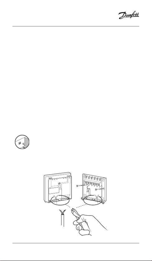
Mounting
VIIOG102 © Danfoss 09/2015
3
Page 4

Installation Guide Danfoss Link™ BR
Danfoss Link™ BR
Elec
Boiler ON/OFF terminals
(if fitted)
Wiring
tronics
1NL 234
230 VAC
Note: Refer to boiler manufacturer’s manual for wiring connections
to the boiler.
Remove
jumper
Z-Wave Inclusion
Ensure that the Danfoss Link™ BR is factory
reset.
Activate “Inclusion” on the Z-Wave
controller.
Press the LED button on
the Danfoss Link™ BR.
Observe both controller
and Danfoss Link™ BR for
status of the process.
When adding, press and release the install button, and observe
that the LED gives a fast green ash.
If adding is successful the LED turns green permanently.
4
VIIOG102 © Danfoss 09/2015
Page 5

Installation Guide Danfoss Link™ BR
Z-Wave Exclusion
Activate “Exclusion” on the Z-Wave controller.
Press and release the button on the Danfoss Link™ BR.
Observe both controller and Danfoss Link™ BR for status of the
process.
Z-Wave Node Information Frame
Each time the LED button is pressed the Danfoss Link™ BR will
and send NIF.
Z-Wave Info
Generic Device Class GENERIC_TYPE_SWITCH_BINARY
Specic Device Class SPECIFIC_TYPE_NOT_USED
Device type Routing slave
SDK 4.28
NWI No
Explorer frames No
Manufacturer ID 0x0002
Product Type ID 0x8005
Product ID 0x2001
Z-Wave Device Classes Device Class Implemented
Generic Device GENERIC_TYPE_SWITCH_BINARY
Specic Device SPECIFIC_TYPE_NOT_USED
VIIOG102 © Danfoss 09/2015
5
Page 6

Installation Guide Danfoss Link™ BR
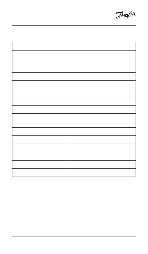
Z-wave Command
Classes Supported
BASIC V1 Change relay state or read relay
ASSOCIATION V2 Change known controller (used
SWITCH_BINARY V1 Change relay state or read relay
MANUFACTURER_
PROPRIETARY
MANUFACTURER_
SPECIFIC
MULTI_CMD V1 Read out Z-Wave version and
VERSION V1 Version of the command classes,
Version Description
state.
Basic Set: Switch Binary Set
Basic Get: Switch Binary Get
Basic Report: Switch Binary Report
by product for optional link test)
1 association grouping is supported.
state
Values:
0x00 = O
0x01 – 0x63 = On
0x64 – 0xFE = No function
0xFF = On
V1 Proprietary Danfoss Protocol
V1 Report manufacturer and product
ID
product version and version of
command classes.
the Z-wave library and the Dan-
foss Link™ BR
6
VIIOG102 © Danfoss 09/2015
Page 7

Installation Guide Danfoss Link™ BR
Perform link test
If controller has sent an ASSOCIATION_SET
with a node ID to the Danfoss Link™ BR, then
it can perform a link test to this node ID by
using 10 no operation commands and count
the received acknowledgements, 2 missing
acknowledgments will result in a failed link
test.
The link test can be started from the Danfoss
Link™ BR by pressing the button for > 2
seconds.
Factory reset
Turn o the power to the device, then press and hold the install
button in front of the device for approx. 5 sec. while the power
is switched on again. The button must be held until LED gives a
red ash.
Status indicator
Green LED ON Relay OFF/Standby
Red LED ON Relay ON/Heating
Green LED fast ash Adding or link test
Green LED short ash Ready for adding
Red LED slow ash Adding not OK
Link test not OK
VIIOG102 © Danfoss 09/2015
7
Page 8
Installation Guide Danfoss Link™ BR
Technical specications
Operation voltage 230 V AC, 50 Hz
Standby consumption 1.6 W
Load
Rated impulse voltage 2.5 kV
Switching Type 1B
Regulation ON/OFF
Ambient temperature 0˚ to +45˚C
Transmission frequency Wireless Z-Wave 868.42 MHz
Transmission range in
normal buildings
Transmission power Max. 1 mW
Pollution situation Degree 2
Ball pressure test 75˚C
Software classication Class A
IP class 40
Dimensions 84 × 84 × 30 mm
3 amps resistive
1 amp inductive
Up to 30 m
8
VIIOG102 © Danfoss 09/2015
Page 9

Installation Guide Danfoss Link™ BR
Disposal instructions
VIIOG102 © Danfoss 09/2015
9
Page 10

Danfoss A/S
Haarupvaenget 11
8600 Silkeborg
Denmark
Phone: +45 7488 8000
Fax: +45 7488 8100
www.danfoss.com
Danfoss can accept no responsibility for possible errors in catalogues, brochures and other printed material.
Danfoss reserves the right to alter its products without notice. This also applies to products already on order
provided that such alterations can be made without subsequential changes being necessary in specications
already agreed.
All trademarks in this material are property of the respective companies. Danfoss and the Danfoss logotype
are trademarks of Danfoss A/S. All rights reserved.
VIIOG102 © Danfoss 09/2015
 Loading...