

Page 1

MAKING MODERN LIVING POSSIBLE
Installation Guide
Danfoss Link™ Hydronic Controller
DANFOSS HEATING SOLUTIONS
Page 2

Installation Guide Danfoss Link™ HC
Content
1. Quick guide for Installation . . . . . . . . . . . . . . . . . . . . . . . . . . . . . . . . . . . . . . . . . . . . . . . . 4
2. Introduction . . . . . . . . . . . . . . . . . . . . . . . . . . . . . . . . . . . . . . . . . . . . . . . . . . . . . . . . . . . . . . 4
3. Functional Overview (g. 2) . . . . . . . . . . . . . . . . . . . . . . . . . . . . . . . . . . . . . . . . . . . . . . . . 4
4. Mounting and Installation Procedure (Sequential) . . . . . . . . . . . . . . . . . . . . . . . . . . . 5
4.1 Danfoss Link™ HC . . . . . . . . . . . . . . . . . . . . . . . . . . . . . . . . . . . . . . . . . . . . . . . . . . . . . . . . . . . . .5
4.2 24 V Actuators . . . . . . . . . . . . . . . . . . . . . . . . . . . . . . . . . . . . . . . . . . . . . . . . . . . . . . . . . . . . . . . . 5
4.3 Relays for Pump and Boiler Control . . . . . . . . . . . . . . . . . . . . . . . . . . . . . . . . . . . . . . . . . . . .5
4.4 Input for Away Function. . . . . . . . . . . . . . . . . . . . . . . . . . . . . . . . . . . . . . . . . . . . . . . . . . . . . . .5
4.5 Input for Heating and Cooling . . . . . . . . . . . . . . . . . . . . . . . . . . . . . . . . . . . . . . . . . . . . . . . . .6
4.6 Wiring . . . . . . . . . . . . . . . . . . . . . . . . . . . . . . . . . . . . . . . . . . . . . . . . . . . . . . . . . . . . . . . . . . . . . . . .6
4.7 Power Supply . . . . . . . . . . . . . . . . . . . . . . . . . . . . . . . . . . . . . . . . . . . . . . . . . . . . . . . . . . . . . . . . .6
4.8 CF-EA External Antenna . . . . . . . . . . . . . . . . . . . . . . . . . . . . . . . . . . . . . . . . . . . . . . . . . . . . . . . 6
5. Conguration . . . . . . . . . . . . . . . . . . . . . . . . . . . . . . . . . . . . . . . . . . . . . . . . . . . . . . . . . . . . . 6
5.1 Adding Danfoss Link™ HC to the system . . . . . . . . . . . . . . . . . . . . . . . . . . . . . . . . . . . . . . .6
5.2 Conguring Danfoss Link™ HC . . . . . . . . . . . . . . . . . . . . . . . . . . . . . . . . . . . . . . . . . . . . . . . .7
5.3 Creating rooms . . . . . . . . . . . . . . . . . . . . . . . . . . . . . . . . . . . . . . . . . . . . . . . . . . . . . . . . . . . . . . .8
5.4 Adding an output to a room . . . . . . . . . . . . . . . . . . . . . . . . . . . . . . . . . . . . . . . . . . . . . . . . . . .8
5.5 Conguring a room . . . . . . . . . . . . . . . . . . . . . . . . . . . . . . . . . . . . . . . . . . . . . . . . . . . . . . . . . . .8
5.6 Performing a network test after adding new devices . . . . . . . . . . . . . . . . . . . . . . . . . . .9
5.7 Leaving the service area in Danfoss Link™ CC . . . . . . . . . . . . . . . . . . . . . . . . . . . . . . . . . .9
6. Maintenance . . . . . . . . . . . . . . . . . . . . . . . . . . . . . . . . . . . . . . . . . . . . . . . . . . . . . . . . . . . . . . 9
6.1 Removing an output . . . . . . . . . . . . . . . . . . . . . . . . . . . . . . . . . . . . . . . . . . . . . . . . . . . . . . . . . .9
6.2 Factory reset . . . . . . . . . . . . . . . . . . . . . . . . . . . . . . . . . . . . . . . . . . . . . . . . . . . . . . . . . . . . . . . . .10
7. Technical Specications . . . . . . . . . . . . . . . . . . . . . . . . . . . . . . . . . . . . . . . . . . . . . . . . . . . 10
8. Troubleshooting . . . . . . . . . . . . . . . . . . . . . . . . . . . . . . . . . . . . . . . . . . . . . . . . . . . . . . . . . . 10
Figures and illustrations
A1 ...............................................................................12
A2 ...............................................................................13
Danfoss Heating Solutions VIFZL402 06/2013
3
Page 3
Installation Guide Danfoss Link™ HC
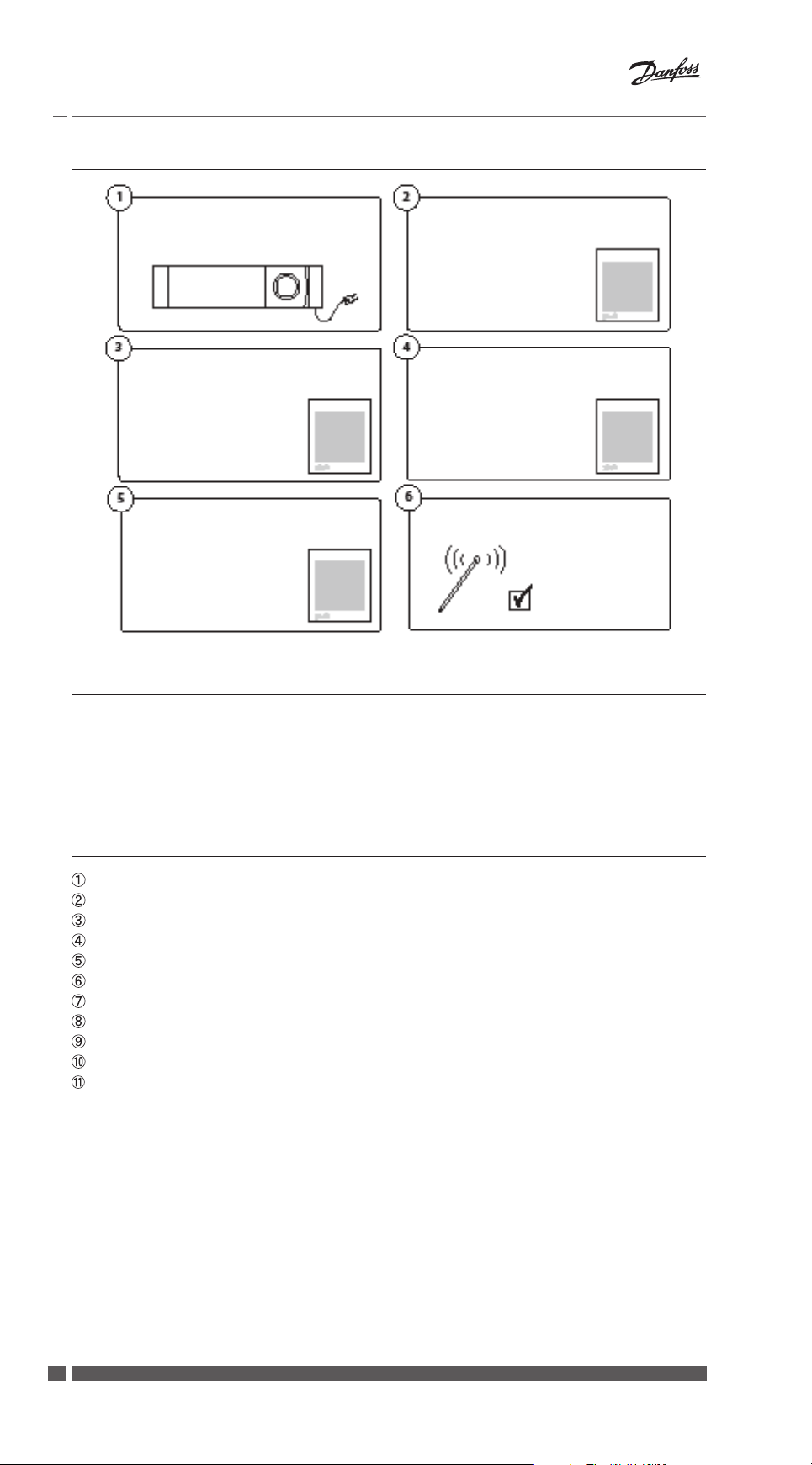
1. Quick guide for Installation
Mount the Danfoss Link™ HC, connect
all actuators (TWA) and power-up the
unit
Create rooms, add outputs and Room
Thermostats - choose output type in
actuator settings
Add any other devices to the system
2. Introduction
Add Danfoss Link™ HC to the
Danfoss Link™ CC as a service device
Check the conguration in
Danfoss Link™ HC setting menu
Perform a network test
Danfoss Link™ is a wireless control system for a variety of heating systems.
The Danfoss Link™ HC is a part of this system allowing wireless control of manifolds for
water based oor heating/cooling.
3. Functional Overview (g. 2)
Output LEDs.
Boiler relay.
Pump relay.
Actuator connections.
Install/Link Test.
External antenna connection.
Front cover release.
Not in use (Input 1).
Away Function (Input 2) (external ON/OFF switch).
Input for heating/cooling (Input 3) (external ON/OFF switch).
Output cable xing.
4
06/2013 VIFZL402 Danfoss Heating Solutions
Page 4

Installation Guide Danfoss Link™ HC
4. Mounting and Installation Procedure (Sequential)
The wireless systems transmission range is sucient for most applications; however, wireless signals are weakened on the way from the Danfoss Link™ to the Room Thermostats
and each building has dierent obstacles.
Checklist for optimal installation and best wireless signal strength (g. 1):
• No metal objects between the Danfoss Link™ HC and the Room Thermostats.
• Wireless signal through walls on shortest possible diagonal distance.
• Optimise the wireless signal by installing a RU Repeater Unit.
Note! Danfoss recommends that an installation plan is made before beginning the actual
installation (g. 1).
4.1 Danfoss Link™ HC
Mount the Danfoss Link™ HC in an horizontal upright position.
Wall:
• Remove the front and side covers (g. 3).
• Mount with screws and wall plugs (g. 3).
DIN-Rail:
• Mount DIN-rail parts (g. 4).
• Click on DIN-rail (g. 5).
• Release from DIN-rail (g. 6).
Important! Complete all the installations on the Danfoss Link™ HC as described below, before
connecting to a 230 V power supply!
4.2 24 V Actuators
• Connect the two actuator wires to an output (g. 7).
• Fix the cable (g. 8).
Note! If NC (normally closed) actuators are installed for ON/OFF regulation, no further actuator
output conguration is needed.
4.3 Relays for Pump and Boiler Control
• Connect wires for pump and boiler controls to their respective output (g. 9).
• Fix the cable (g. 10).
Note! The relays for pump and boiler are potential free contacts and can therefore NOT be used
as direct power supply. Max. load is 230 V and 8 A/2 A!
4.4 Input for Away Function
• Connect an external ON/OFF switch to the terminals for Away Function (Input 2). When
this switch is closed (ON) the system will override all room thermostat set points and
change the temperature to 15 °C (g. 11).
• Fix the cable (g. 12).
Note! The Away Function ensures a set room temperature xed at 15 °C for all room thermostats, but it can be changed with the Danfoss Link™ CC.
Danfoss Heating Solutions VIFZL402 06/2013
5
Page 5

Installation Guide Danfoss Link™ HC
50 Hz
4.5 Input for Heating and Cooling
• Connect an external ON/OFF switch to the terminals for Heating and Cooling (Input 3)
(g. 13). With the switch closed (ON), the system will switch from heating to cooling
mode.
• Fix the cable (g. 14).
Note! With the system in cooling mode, the actuator output will be activated (ON for NC actuators/OFF for NO actuators), when the temperature in a room exceeds the set point.
When the system is in cooling mode a dew-point sensor should be installed.
4.6 Wiring
Input Relays Actuator outputs
Input 1
Input 2
Input 3
910876 54321
External
antenna
Max. 3 m
230 V~
4.7 Power Supply
Connect all actuators (TWA), before mains powering the unit!
!
Then, connect the Danfoss Link™ HC power supply plug to a 230 V power supply, when all
actuators, pump and boiler controls and other inputs are installed. The Danfoss Link™ HC is
now ready to be added to the Danfoss Link™ CC.
Note! If the power supply plug is removed from the power supply cable during installation,
ensure that the connection is made according to existing law/legislation.
4.8 CF-EA External Antenna
The CF-EA is installed as diverter when there is no transmission possible through a large
building, heavy construction or metal barrier, e.g. if the Danfoss Link™ HC is located in a
metal cabinet/box.
• Remove the plastic cover from the antenna connection on the Danfoss Link™ HC
(g. 15).
• Connect the CF-EA (g. 16).
• Place the CF-EA on the other side of the transmission barrier away from the
Danfoss Link™ HC.
5. Conguration
5.1 Adding Danfoss Link™ HC to the system
Note! Adding Danfoss Link™ HC to a system is made from the Danfoss Link™ CC.
For further information, see separate instruction.
• Remove the front cover of the Danfoss Link™ CC by
gently pulling it o, pull near the edges of the cover.
• Press the SETUP pin for 3 seconds to enter the service
area.
Important!
• The Danfoss Link™ HC must be added to the network as a service device. For further
instructions on network inclusion, see more information in the Danfoss Link™ CC
Installation Guide.
• Add any dedicated repeater units (CF-RU) BEFORE adding the Danfoss Link™ HC to the
wireless network.
6
06/2013 VIFZL402 Danfoss Heating Solutions
Page 6

Installation Guide Danfoss Link™ HC
Service Options
1
Rooms and Devices
?
Click here for adding the Danfoss Link™ HC
Note! During installation, the distance between the Danfoss Link™ CC and the
Danfoss Link™ HC must not exceed 1.5m.
5.2 Conguring Danfoss Link™ HC
Note! Conguring Danfoss Link™ HC is made from the Danfoss Link™ CC.
For further information, see separate instruction.
Rooms and Devices
2
Add Service Device
Add Service Device
3
Begin Registration
?
?
Service Options
1
Rooms and Devices
Conguring outputs
Congure Device Congure Device Setup Relays
1
Setup Setup Relays Choose settings
Conguring inputs
Congure Device
?
?
Rooms and Devices
2
Manage Devices
2
Setup Inputs
?
?
Manage Devices
3
Congure Device
?
3
?
Input
1
Setup Inputs
?
Danfoss Heating Solutions VIFZL402 06/2013
2
Select Input
?
3
Choose setting
?
7
Page 7

Installation Guide Danfoss Link™ HC
5.3 Creating rooms
Danfoss recommends to create and add device(s) to one room in a single step, and thereafter move on to the next room.
Service Options
1
Rooms and Devices
?
5.4 Adding an output to a room
Note! Conguring Danfoss Link™ HC is made from the Danfoss Link™ CC.
For further information, see separate instruction.
Congure Room
1
Room devices
?
Rooms and Devices
2
Add New Room
Room Devices
2
Add a device
Edit Room Name
3
Enter/Edit Room Name
?
Room Devices
3
Use an output
?
?
?
Select Device
4
Select
?
Actuator Settings
7
Select type / OK
?
5.5 Conguring a room
Congure Room
1
Heating regulation
?
Select Output
5
Select from list
Heating Regulation
2
Select type
Select Heating Emitter
6
Actuator Setting
?
Forecasting method:
By activation of the forecast method, the system
will automatically predict
the heating start-up time
necessary to reach desired
room temperature at desired time.
?
?
8
06/2013 VIFZL402 Danfoss Heating Solutions
Page 8

Installation Guide Danfoss Link™ HC
5.6 Performing a network test after adding new devices
After nishing installation, perform a network test to ensure that communication between
added devices and the Danfoss Link CC™ is stable.
Note! Do not perform the network test before the Danfoss Link™ CC is mounted in its nal
position.
Service Options
1
Status and Diagnostics
?
At the end of the network test the Danfoss Link™ CC awaits for all battery operated devices
to wake up and report. Follow the instructions given on the screen. If the network test is
running smoothly, there will be no need for further interaction. If the network test is performing slow, the Danfoss Link™ CC guides through troubleshooting and gives useful tips
for speeding up the process.
5.7 Leaving the service area in Danfoss Link™ CC
Press the SETUP pin for 3 seconds and put back the front cover to the Danfoss Link™ CC.
Status and Diagnostics
2
Network
?
Wireless Network Status
3
Start Network Test
?
6. Maintenance
6.1 Removing an output
Service Options
Rooms and Devices
Select Room
1
Rooms and Devices
Congure Room
4
Room devices
Remove Output
7
Yes, remove output now
?
?
2
Manage Devices
Room Devices
5
Remove a device
?
?
3
Select existing room
?
Room Devices
6
Remove an output
?
?
Danfoss Heating Solutions VIFZL402 06/2013
9
Page 9

Installation Guide Danfoss Link™ HC
6.2 Factory reset
• Disconnect the power supply for the Danfoss Link™ HC.
• Wait for green LED to turn o.
• Press and hold the Install/Link Test (g. 2 ).
• While holding Install/Link Test, reconnect the power supply.
• Release the Install/Link Test, when the LEDs are on.
7. Technical Specications
Transmission frequency 862.42 MHz
Transmission range in normal constructions (up to) 30 m
Transmission power < 1 mW
Supply voltage 230 V AC
Actuator outputs 5 or 10 x 24 V DC
Max. continued output load (total) 35 VA
Relays 230 V AC/8 (2) A
Ambient temperature 0 - 50 °C
IP class 30
8. Troubleshooting
Error indication Possible Causes
Impossible to add devices to the
Danfoss Link™ CC system
The connection to a device is lost - Empty/low battery
Actuator (TWA) not visible on
Danfoss Link™ CC
Flashing output/alarm LEDs - Output or actuator is short-circuited
High room temperature (above comfort
settings)
The distance between the Danfoss Link™
CC and the Danfoss Link™ HC has exceeded
1.5m.
For further information, see separate instruction for the Danfoss Link™ CC.
- The wireless signal is weak
- Defective device
For further information, see separate instruction for the Danfoss Link™ CC.
- Actuator incorrectly mounted
- Defective actutator
- The actuator is disconnected
Degraded mode. (The actuator will be activated with a 25% duty cycle - caused by lost
connection to a device)
10
06/2013 VIFZL402 Danfoss Heating Solutions
Page 10

Installation Guide Danfoss Link™ HC
Danfoss Heating Solutions VIFZL402 06/2013
11
Page 11

Installation Guide Danfoss Link™ HC
A1
Fig. 1
Danfoss
Link™ RS
Danfoss
Link™ HC
Fig. 2
Metal
Danfoss Link™ RS
Danfoss
Link™ RS
!
Metal
!
Danfoss Link™ CC
Danfoss
Link™ HC
Danfoss Link™ CC
!
Fig. 3
12
06/2013 VIFZL402 Danfoss Heating Solutions
Page 12

Installation Guide Danfoss Link™ HC
A2
Fig. 4 Fig. 5 Fig. 6
Fig. 7 Fig. 8
Fig. 9 Fig. 10
Fig. 11 Fig. 12
Fig. 13 Fig. 14
Fig. 15 Fig. 16
Danfoss Heating Solutions VIFZL402 06/2013
13
Page 13

Danfoss A/S
Indoor Climate Solutions
Ulvehavevej 61
7100 Ve jle
Denmark
Phone: +45 748 8 8500
Fax: +45 7488 8501
Email: heating.solutions@danfoss.com
www.heating.danfoss.com
VIFZL402
088N2776 | 06.2013 | Version 01
 Loading...