

Page 1
Technical Information
LDU20/24
Closed Circuit Axial Piston Transmission
www.danfoss.com
Page 2
Technical Information
LDU20/24 Closed Circuit Axial Piston Transmission
Revision history Table of revisions
Date Changed Rev
May 2021 Added Size 24 0301
January 2021 Minor update in Physical Properties 0208
December 2020 Minor correction 0207
Novemebr 2020 Minor update 0206
June 2020 Changed document number from 'BC00000192' and 'L1124546' to 'BC152886483777' 0205
April 2019 Fixed Control Handle Requirements 0103
April 2018 Minor update 0102
June 2016 Converted to New Danfoss layout 0101
December 2014 Converted to DITA CMS AD
March 2013 Paint and Tag AC
March 2011 2nd edition AB
January 2011 First edition AA
2 | © Danfoss | May 2021 BC152886483777en-000301
Page 3

Technical Information
LDU20/24 Closed Circuit Axial Piston Transmission
Contents
General description
Basic Design........................................................................................................................................................................................4
Key Features....................................................................................................................................................................................... 4
Typical Applications........................................................................................................................................................................ 4
Schematic diagram..........................................................................................................................................................................4
Technical Specification
Physical properties...........................................................................................................................................................................5
Operation Parameters.....................................................................................................................................................................5
Fluid Specifications..........................................................................................................................................................................6
Operations
Check / High Pressure Relief Valve ............................................................................................................................................7
Bypass Function................................................................................................................................................................................8
CPRV (Charge Pressure Relief Valve)..........................................................................................................................................9
Control............................................................................................................................................................................................... 10
Direct Displacement Control................................................................................................................................................10
Control Handle Requirements ............................................................................................................................................ 10
Operating Parameters
Overview........................................................................................................................................................................................... 11
Input Speed......................................................................................................................................................................................11
System Pressure..............................................................................................................................................................................11
Input Power......................................................................................................................................................................................11
Charge Pressure..............................................................................................................................................................................11
Case pressure...................................................................................................................................................................................12
Viscosity.............................................................................................................................................................................................12
Temperature.................................................................................................................................................................................... 12
System Design Parameters
Filtration System ............................................................................................................................................................................13
Filtration............................................................................................................................................................................................ 14
Charge Filtration....................................................................................................................................................................... 14
Suction Filtration.......................................................................................................................................................................14
Independent Braking System....................................................................................................................................................15
Fluid Selection.................................................................................................................................................................................15
Reservoir............................................................................................................................................................................................15
Case Drain.........................................................................................................................................................................................15
Charge Pump...................................................................................................................................................................................15
Bearing Loads and Life.................................................................................................................................................................16
Applications with External Shaft Loads............................................................................................................................16
Input Shaft...................................................................................................................................................................................17
Shaft Torque Rating and Spline Lubrication...................................................................................................................18
Shaft Availability and Torque Ratings...............................................................................................................................18
Sizing Equations............................................................................................................................................................................. 19
Model Code
Model Code: A - H.......................................................................................................................................................................... 20
Model Code: J - M...........................................................................................................................................................................21
Model Code: N - Z...........................................................................................................................................................................22
Installation Drawings
Shaft Availability and Torque Ratings: Input Shaft/PTO Shaft.......................................................................................23
Shaft Availability and Torque Ratings: Output Shaft........................................................................................................ 24
Installation Drawings LDU20/24...............................................................................................................................................25
Center section: Option A.............................................................................................................................................................27
Center section: Option B............................................................................................................................................................. 28
Center section: Option F..............................................................................................................................................................29
Center section: Option H.............................................................................................................................................................30
©
Danfoss | May 2021 BC152886483777en-000301 | 3
Page 4
MA1
MB1
MA2
MB2
L1
L2
L3
S
M3
P400004
Technical Information
LDU20/24 Closed Circuit Axial Piston Transmission
General description
Basic Design
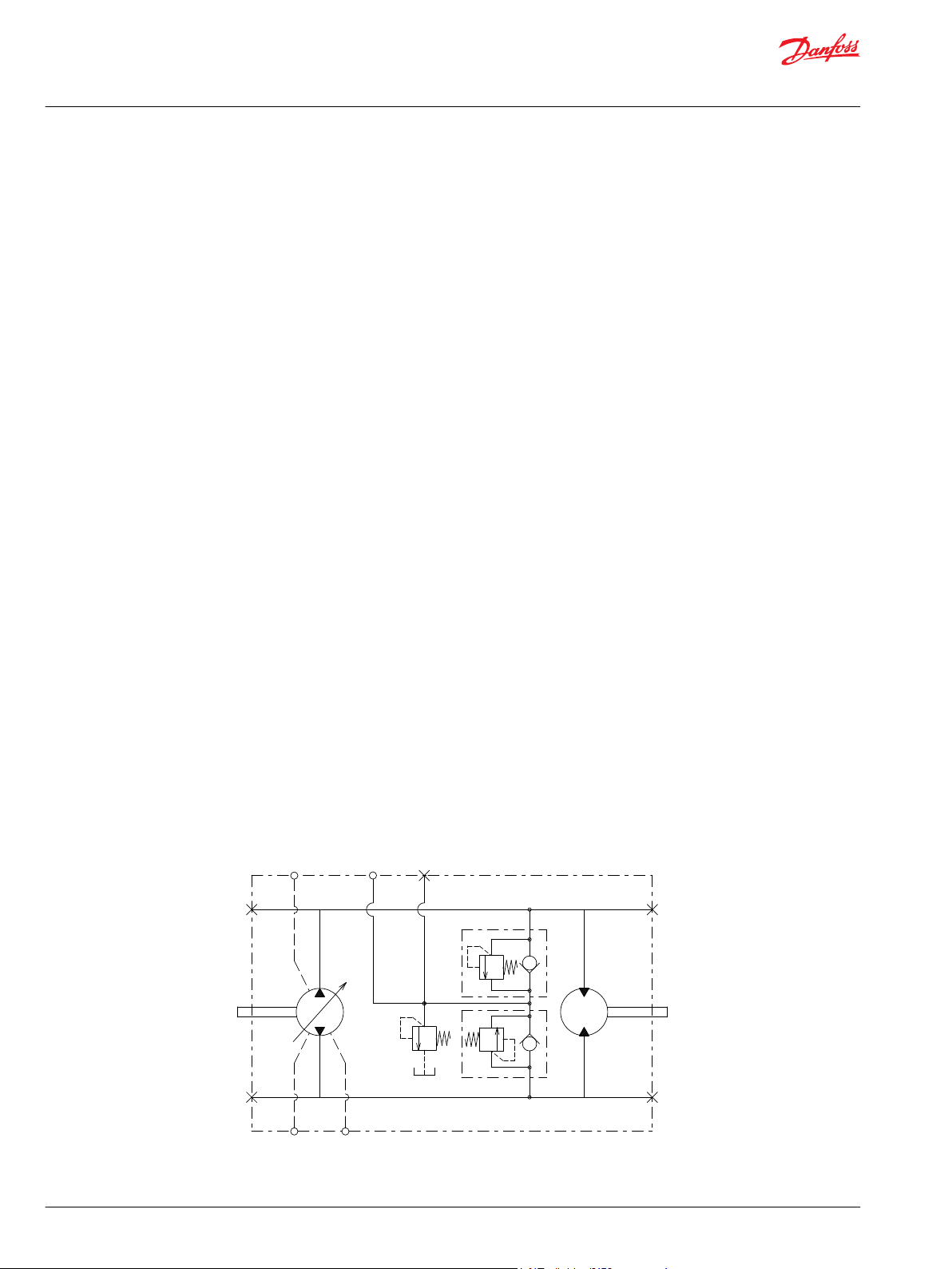
LDU20/24 is a kind of U-style HST hardware, including a closed circuit variable displacement piston pump
with DDC (Direct displacement control) and a fixed motor. LDU20/24 is specially designed with optimized
performance, size, and cost, in order to fulfill the demand of the mobile applications marketplace. This
document provides the detailed specifications and features for LDU20/24.
Key Features
Easy to use design as Complete Hydrostatic Transmission package for Turf care machines & Compact
•
Utility Tractors up to 26 kw[35 PS]
Compact design
•
U-style layout in One housing with Z-shaft configuration
•
Require external charge
•
Bypass valve to allow the vehicle to be towed
•
Same shaft center distance as BDU21 85mm…Between pump and motor shaft
•
Same drive line design is available between BDU21 and LDU20/24
•
Best in class Efficiency by Female Piston & Male slipper design…Can reach approximately 80% overall
•
efficiency
Longer life kit, Higher Duty Cycle capability in the most compact design in this class of HST
•
Low trunnion operating force
•
Serviced by a Worldwide Network of Danfoss
•
Typical Applications
Schematic diagram
Compact utility tractor
•
Turf care
•
Small agricultural machinery
•
4 | © Danfoss | May 2021 BC152886483777en-000301
Page 5
Technical Information
LDU20/24 Closed Circuit Axial Piston Transmission
Technical Specification
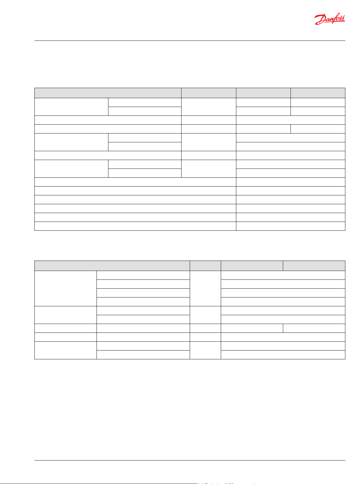
Physical properties
Features Units LDU20 LDU24
Displacement
Recommended charge pump displacement for external charge supply cm3/rev [in3/rev] 6 [0.37]
Torque at maximum displacement (theoretical)
Mass moment of inertia of
rotating components
Weight dry kg [lb] 14.1 [31.1]
Oil volume
Installation See Installation Drawings on page 25-30
Rotation Clockwise or Counterclockwise
Ports (ISO 11926-1) See Installation Drawings on page 25-30
Input shafts and PTO shafts See Installation Drawings on page 23
Output shaft See Installation Drawings on page 24
Control type DDC
1
Max Swash angle is 18 deg.
Pump side
Motor side 20 [1.22] 24 [1.46]
Pump side
Motor side 0.000928 [0.000683]
Case only
With passage 1.2 [0.32]
1
cm3/rev [in3/rev]
N•m/bar [lbf•in/1000 psi]
kg•m2 [slug•ft2]
liter [US gal]
0-20 [0-1.22] 0-24 [0-1.46]
0.32 [195.2] 0.38 [234.2]
0.000936 [0.000693]
1.1 [0.28]
Operation Parameters
Features Units LDU20 LDU24
Minimum for external charge supply
Input speed
System pressure
Input power Maximum kw [PS] 22 [30] 26 [35]
Charge pressure Minimum bar [psi] 5 [73]
Case pressure
Minimum for full performance 1300
Rated 3400
Maximum 3800
Maximum working pressure
Maximum pressure 345 [500]
Rated
Maximum 3 [43.5]
min-1 (rpm)
bar [psi]
bar [psi]
500
300 [4350]
1 [14.5]
©
Danfoss | May 2021 BC152886483777en-000301 | 5
Page 6
Technical Information
LDU20/24 Closed Circuit Axial Piston Transmission
Technical Specification
Fluid Specifications
Features Units LDU20/24
Viscosity
Temperature
Filtration
(recommended minimum)
Minimum
Recommended range 12-60 [66-280]
Maximum 1600 [7500]
Minimum
Recommended range +82 [+180]
Maximum +104 [+220]
Cleanliness per ISO 4406 22/18/13
Efficiency (charge pressure filtration)
Efficiency (suction and return line
filtration)
Recommended inlet screen mesh
size
mm2/sec. [ SUS]
Degrees C [Degrees F]
β-ratio
µm 100-125
7 [49]
-40 [-40]
β15-20=75(β10≥10)
β15-20=75(β10≥10)
6 | © Danfoss | May 2021 BC152886483777en-000301
Page 7
P400005
C
Technical Information
LDU20/24 Closed Circuit Axial Piston Transmission
Operations
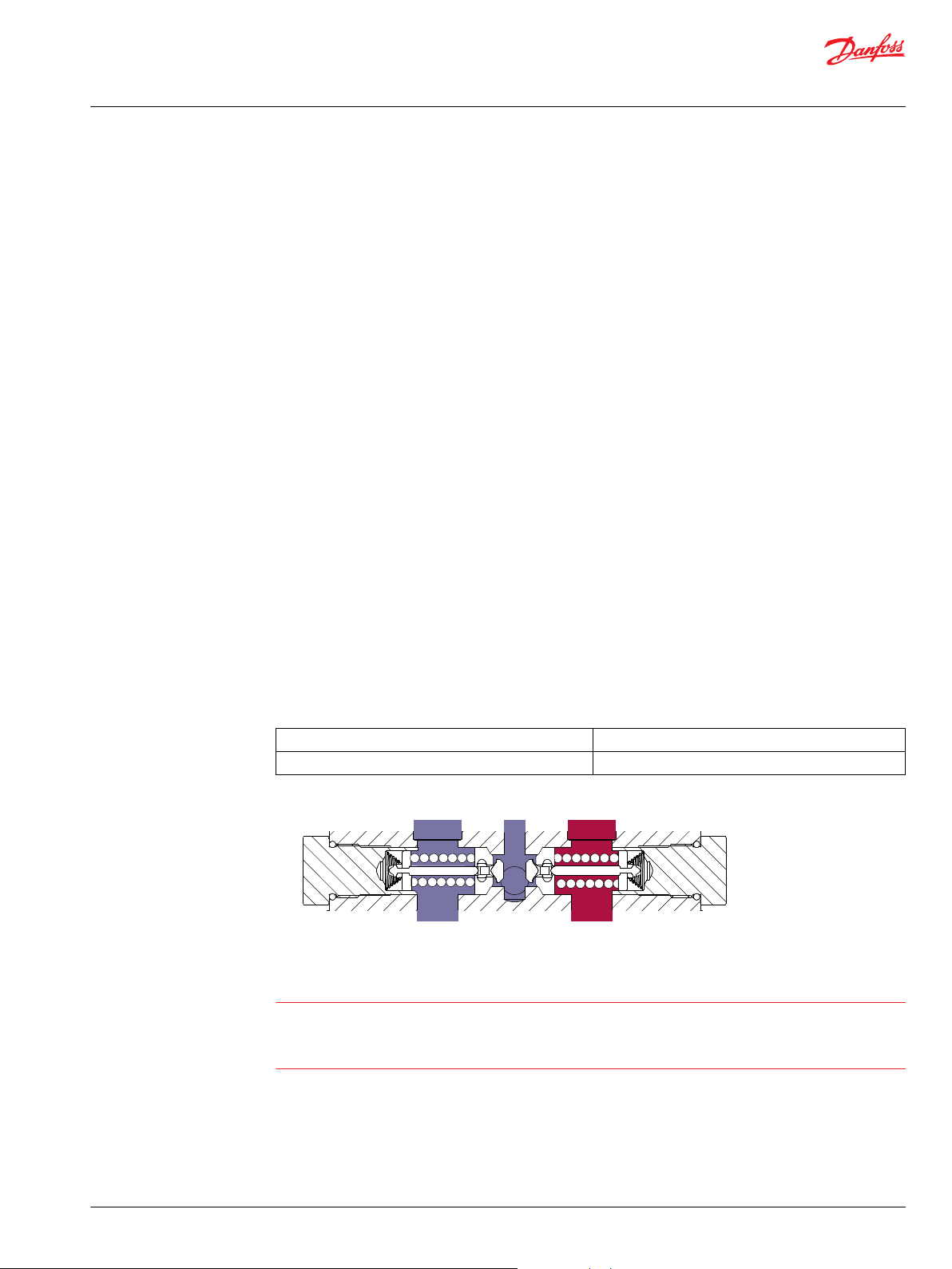
Check / High Pressure Relief Valve
LDU20/24 is equipped with a combination high pressure relief and charge check valve. The high-pressure
relief function is a dissipative (with heat generation) pressure control valve for the purpose of limiting
excessive system pressures. The charge check function acts to replenish the low-pressure side of the
working loop with charge oil. Each side of the transmission loop has a dedicated HPRV valve that is nonadjustable with a factory set pressure. When system pressure exceeds the factory setting of the valve, oil
is passed from the high pressure system loop, into the charge gallery, and into the low pressure system
loop via the charge check.
The order code allows for different pressure settings to be used at each system port. HPRV valve with
orifice is available to gain wider neutral dead-band. When HPRV valves with orifice are used, it is only for
High pressure ports when vehicle goes in reverse. The system pressure order code for transmissions with
only HPRV is a reflection of the HPRV setting.
The system pressure order code for transmissions configured with pressure limiter and HPRV is a
reflection of the pressure limiter setting.
Check/High pressure relief valve with orifice
As an option, LDU20/24 offers Check / HPRV with an orifice produce a larger neutral deadband.
In some applications, it is desirable to use Check / HPRV with an orifice to expand null dead band, which
would help provide a larger margin of safety for vehicle movement in neutral and provide easier
adjustment of the vehicle linkage for machine neutral. The orifice connects the working loop, which is a
main hydraulic circuit, to a charge circuit. It always allows some internal leakage to ensure the expanding
null dead band around neutral position of control shaft. However, it decreases the volumetric efficiency,
particularly at high system pressure in the working loop. Check / HPRV with an orifice has possibility to
increase downhill creap. It is recommended to install the orifice in a specific working loop, which is
pressurized when the vehicle moves in reverse.
The HPRV are set at the following flow rates
Check/HPRV without orifice 5 l/min [1.3 US gal/min]
Check/HPRV with orifice 17 l/min [4.5 US gal/min]
Caution
HPRV´s are factory set at a low flow condition. Any application or operating condition which leads to
elevated HPRV flow will cause a pressure rise with flow above a valve setting. Consult factory for
application review.
©
Danfoss | May 2021 BC152886483777en-000301 | 7
Page 8
System Pressure
Bypass Valve
System Pressure
P400006
C
Technical Information
LDU20/24 Closed Circuit Axial Piston Transmission
Operations
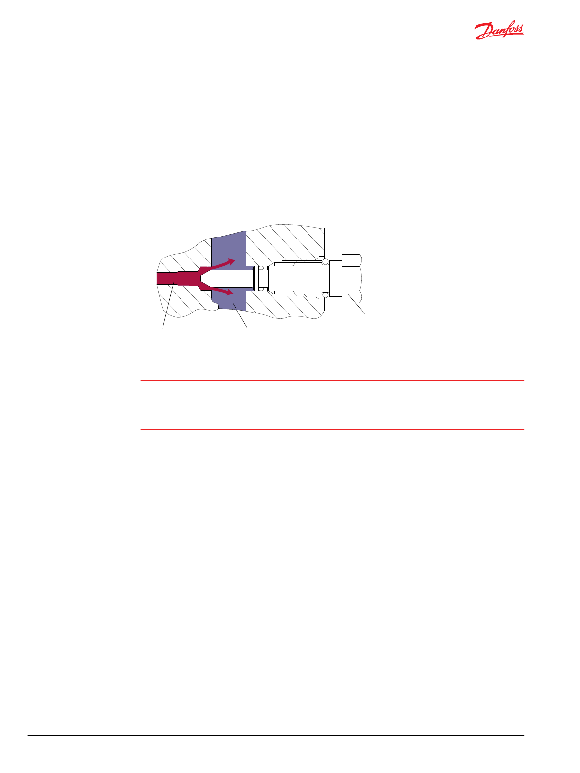
Bypass Function
The LDU20/24 contains a dedicated bypass valve option. The bypass function is activated when the
bypass valve is mechanically backed out 3 full turns (maximum). The bypass function allows a machine or
load to be moved without rotating the pump shaft or prime mover. In some applications, it is desirable to
bypass the fluid around the variable displacement pump when pump shaft rotation is unachievable or
undesired. To illustrate, an inoperable vehicle may need to be moved to the service or the repair location,
or winched onto a trailer without operating the prime mover. Thus, LDU20/24 is designed with the
bypass function as an option.
Bypass Function
Caution
Excessive speed or extended movement will damage the transmission.
Avoid excessive speeds and extended load/vehicle movement. Do not move the load or vehicle more
than 20 % of maximum speed or for longer than 3 minutes. When the bypass function is no longer
needed, reseat the bypass valve to the normal operating position.
8 | © Danfoss | May 2021 BC152886483777en-000301
Page 9
Charge Flow
P400007
Technical Information
LDU20/24 Closed Circuit Axial Piston Transmission
Operations
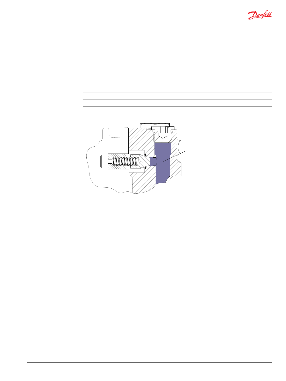
CPRV (Charge Pressure Relief Valve)
The charge pressure relief valve maintains charge pressure at a designated level above case pressure. The
charge pressure relief valve is a direct acting poppet valve which opens and discharges fluid to the HST
case when pressure exceeds a designated level. For external charge flow the CPRV is set according to
below table. The charge pressure relief valve setting is specified on the model code of the transmission.
Charge Pressure Relief Valve settings for external charge supply
LDU 20/24 10.8 [2.9]
Charge Pressure Relief Valve Function
Flow l/min [US gal/min]
©
Danfoss | May 2021 BC152886483777en-000301 | 9
Page 10
W
Technical Information
LDU20/24 Closed Circuit Axial Piston Transmission
Operations
Control
Direct Displacement Control
The LDU20/24 features Direct Displacement Control (DDC) .The swashplate angle is set directly by a
control lever or linkage attached directly to the swashplate trunnion. Control lever movement changes
the speed and rotating direction of the motor by increasing or decreasing the swashplate angle.
The control input shaft is configurable on both of left and right hand side of the LDU20/24.
Control Handle Requirements
Maximum allowable trunnion torque is 79.1 N•m [700 lbf•in]. The approximate torque necessary to rotate
the control arm at 300 bar system operating pressure and 3000 rpm is 25 N•m with the standard
valveplate. Minimum torque necessary to hold the swashplate at a zero angle for neutral is 2.3 N•m [20
in•lbf ]. The actual value will vary due to the influence of pump operating conditions. For mating
dimensions, see Installation Drawings LDU20/24 on page 25.
Input shaft rotation CW CCW
Trunnion location Right Left Right Left
Trunnion rotation CW CCW CW CCW CW CCW CW CCW
Output rotation CCW CW CW CCW CW CCW CCW CW
High pressure port MA MB MB MA MB MA MA MB
Low pressure port MB MA MA MB MA MB MB MA
Warning
With no external forces applied to the swashplate trunnion, internal hydraulic forces may not return the
swashplate to the neutral position under all conditions of operation.
10 | © Danfoss | May 2021 BC152886483777en-000301
Page 11

W
Technical Information
LDU20/24 Closed Circuit Axial Piston Transmission
Operating Parameters
Overview
This section defines the operating parameters and limitations for LDU20/24 with regard to input speeds
and pressures. For actual parameters, refer to Operating Parameters in the Technical Specifications
section.
Input Speed
Minimum speed is the lowest input speed recommended during engine idle condition. Operating below
minimum speed limits pump’s ability to maintain adequate flow for lubrication and power transmission.
Rated speed is the highest input speed recommended at full power condition. Operating at or below
this speed should yield satisfactory product life.
Maximum speed is the highest operating speed permitted. Exceeding maximum speed reduces product
life and can cause loss of hydrostatic power and braking capacity. Never exceed the maximum speed
limit under any operating conditions.
Operating conditions between rated speed and maximum speed should be restricted to less than full
power and to limited periods of time. For most drive systems, maximum unit speed occurs during
downhill braking or negative power conditions.
Warning
System Pressure
Input Power
Unintended vehicle or machine movement hazard.
Exceeding maximum speed may cause a loss of hydrostatic drive line power and braking capacity. You
must provide a braking system, redundant to the hydrostatic transmission, sufficient to stop and hold the
vehicle or machine in the event of hydrostatic drive power loss.
System pressure is the differential pressure between system ports A & B. It is the dominant operating
variable affecting hydraulic unit life. High system pressure, which results from high load, reduces
expected life. Hydraulic unit life depends on speed and normal operating—or weighted average—
pressure that you can only determine from a duty cycle analysis.
Maximum Working Pressure is the highest recommended Application pressure. Maximum working
pressure is not intended to be a continuous pressure. Propel systems with Application pressures at, or
below, this pressure should yield satisfactory unit life given proper component sizing.
Maximum pressure (peak) is the highest intermittent pressure allowed under any circumstances.
Applications with applied pressures between rated and maximum require factory approval with
complete application, duty cycle, and life expectancy analysis.
All pressure limits are differential pressures referenced to low loop (charge) pressure. Subtract low loop
pressure from gauge readings to compute the differential.
Maximum continuous input power is the highest recommended input power to HST excluding PTO
output power.
Charge Pressure
An internal charge relief valve regulates charge pressure. Charge pressure maintains a minimum pressure
in the low side of the transmission loop. Charge pressure is the differential pressure above case pressure.
Minimum charge pressure is the lowest pressure safe working conditions allow in the system.
©
Danfoss | May 2021 BC152886483777en-000301 | 11
Page 12

C
Technical Information
LDU20/24 Closed Circuit Axial Piston Transmission
Operating Parameters
Case pressure
Under normal operating conditions, the rated case pressure must not be exceeded. During cold start case
pressure must be kept below maximum intermittent case pressure. Size drain plumbing accordingly.
Caution
Possible component damage or leakage
Operation with case pressure in excess of stated limits may damage seals, gaskets, and/or housings,
causing external leakage. Performance may also be affected since charge and system pressure are
additive to case pressure.
Viscosity
Maintain fluid viscosity within the recommended range for maximum efficiency and bearing life.
Minimum viscosity should only occur during brief occasions of maximum ambient temperature and
severe duty cycle operation. Maximum viscosity should only occur at cold start. Limit speeds until the
system warms up. Refer to Fluid Specifications on page 6
Temperature
1. Maintain fluid temperature within the limits shown in the table.
Minimum
temperature
Maximum
temperature
2. Measure maximum temperature at the hottest point in the system.
Refer to Fluid specifications for specifications.
3. Ensure fluid temperature and viscosity limits are concurrently satisfied.
relates to the physical properties of the component materials. Cold oil will not
affect the durability of the components, however, it may affect the ability of
the transmission to provide flow and transmit power.
is based on material properties. Don’t exceed it.
12 | © Danfoss | May 2021 BC152886483777en-000301
Page 13

Technical Information
LDU20/24 Closed Circuit Axial Piston Transmission
System Design Parameters
Filtration System
To prevent premature wear, ensure that only clean fluid enters the hydrostatic transmission circuit. A
filter capable of controlling the fluid cleanliness to ISO 4406, class 22/18/13 (SAE J1165) or better, under
normal operating conditions, is recommended.These cleanliness levels cannot be applied for hydraulic
fluid residing in the component housing/case or any other cavity after transport.
Filtration strategies include suction or pressure filtration. The selection of a filter depends on a number of
factors including the contaminant ingression rate, the generation of contaminants in the system, the
required fluid cleanliness, and the desired maintenance interval. Filters are selected to meet the above
requirements using rating parameters of efficiency and capacity.
Filter efficiency can be measured with a Beta ratio1 (βX). For simple suction-filtered closed circuit
transmissions and open circuit transmissions with return line filtration, a filter with a β-ratio within the
range of β
and closed circuits with cylinders being supplied from the same reservoir, a higher filter efficiency is
recommended. This also applies to systems with gears or clutches using a common reservoir. For these
systems, a charge pressure or return filtration system with a filter β-ratio in the range of β
10) or better is typically required.
Because each system is unique, only a thorough testing and evaluation program can fully validate the
filtration system. Please see Design Guidelines for Hydraulic Fluid Cleanliness Technical Information,
BC152886482150 for more information.
= 75 (β10 ≥ 2) or better has been found to be satisfactory. For some open circuit systems,
35-45
= 75 (β10 ≥
15-20
Cleanliness level and βx-ratio
Cleanliness per ISO 4406 22/18/13
Filtration
(recommended
minimum)
Efficiency (charge pressure filtration) β
Efficiency (suction and return line filtration) β
Recommended inlet screen mesh size 100 – 125 µm
= 75 (β10 ≥ 10)
15-20
= 75 (β10 ≥ 2)
35-45
1
Filter βx-ratio is a measure of filter efficiency defined by ISO 4572. It is defined as the ratio of the number of particles greater than a
given diameter (“x” in microns) upstream of the filter to the number of these particles downstream of the filter.
©
Danfoss | May 2021 BC152886483777en-000301 | 13
Page 14

P400009
Technical Information
LDU20/24 Closed Circuit Axial Piston Transmission
System Design Parameters
Filtration
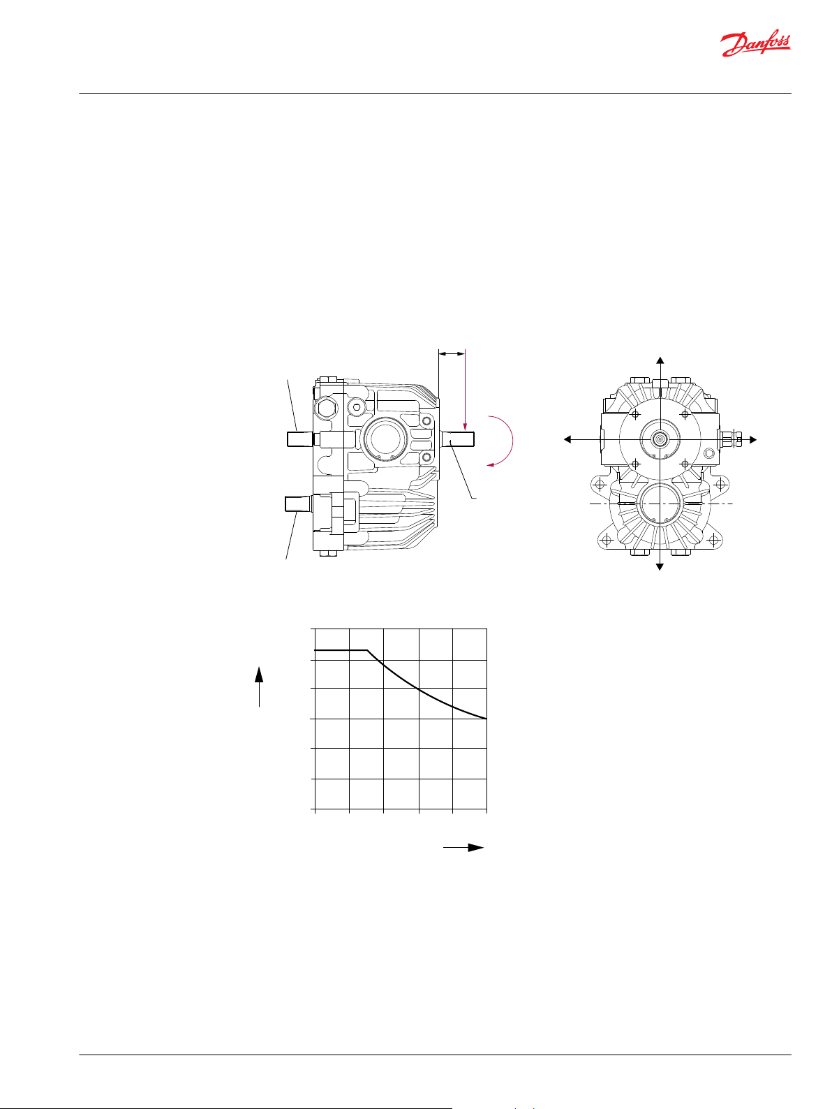
Charge Filtration
The pressure filter is remotely mounted in the circuit after the charge pump, as shown in the
accompanying illustration.
Filters used in charge pressure filtration circuits must be rated to at least 34.5 bar [500 psi] pressure.
Danfoss recommends locating a 100 - 125 µm screen in the reservoir or in the charge inlet line when
using charge pressure filtration.
A filter bypass valve is necessary to prevent damage to the system. In the event of high pressure drop
associated with a blocked filter or cold start-up conditions, fluid will bypass the filter. Avoid working with
an open bypass for an extended period. We recommend a visual or electrical bypass indicator. Proper
filter maintenance is mandatory.
Charge filtration
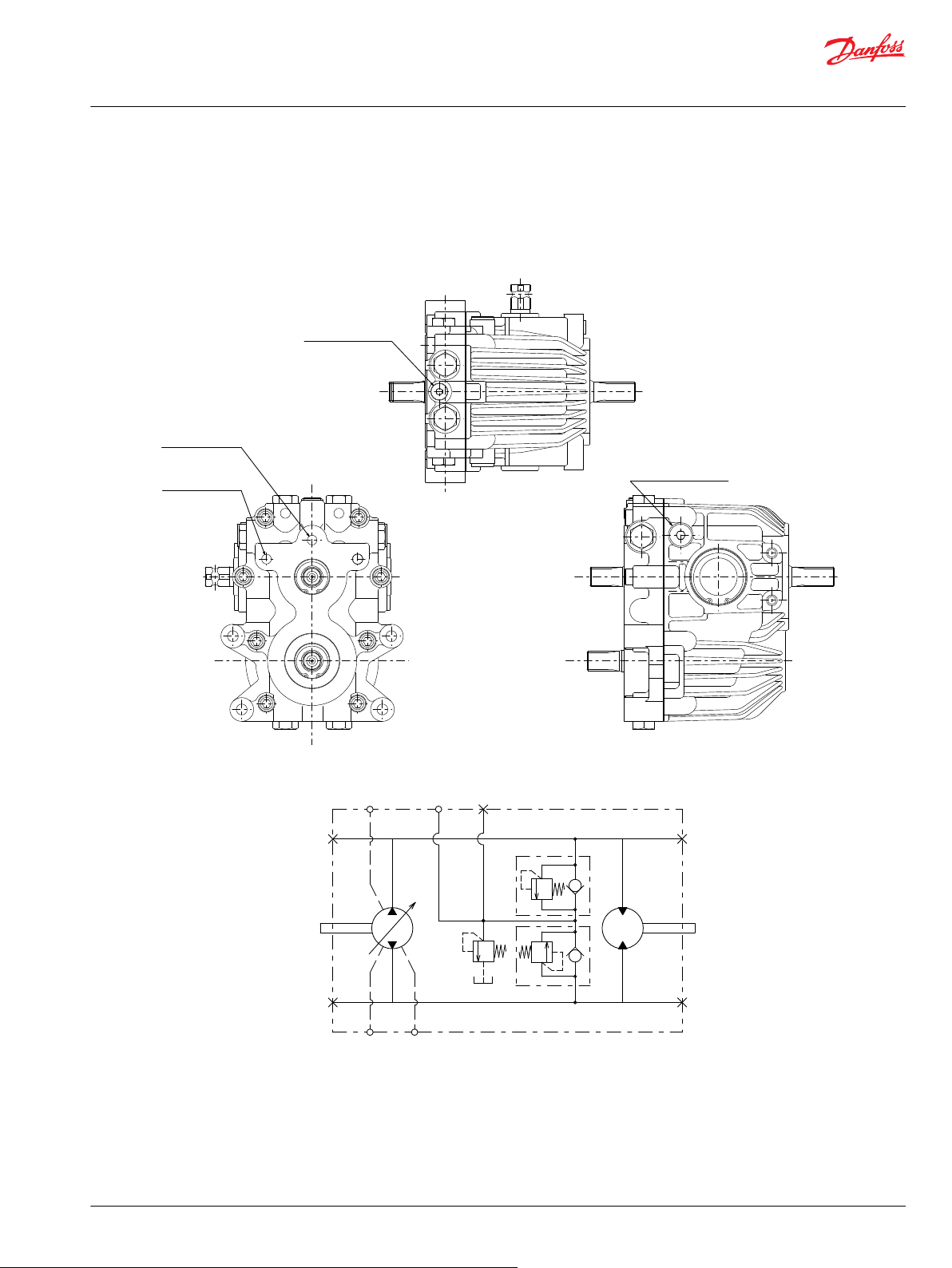
Suction Filtration
The suction filter is placed in the circuit between the reservoir and the inlet to the charge pump as shown
in the accompanying illustration.
Suction filtration
14 | © Danfoss | May 2021 BC152886483777en-000301
Page 15

W
C
Technical Information
LDU20/24 Closed Circuit Axial Piston Transmission
System Design Parameters
Independent Braking System
Vehicle propel applications may require a provision for non-linear control input to reduce control
sensitivity near neutral. Damping or frictional forces may be necessary to produce the desired control
feeling.
These units do not include any neutral centering device for the swashplate. It is necessary to provide a
force in the machine’s control system that will hold the swashplate at the desired angle. A “ fail safe
“ which will return the swashplate to the neutral in the event of linkage failure is recommended.
Warning
Unintended vehicle or machine movement hazard.
The loss of hydrostatic drive line power, in any mode of operation (forward, neutral, or reverse) may cause
the system to lose hydrostatic braking capacity. You must provide a braking system, redundant to the
hydrostatic transmission, sufficient to stop and hold the vehicle or machine in the event of hydrostatic
drive power loss.
Fluid Selection
Ratings and performance data are based on operating with hydraulic fluids containing oxidation, rust
and foam inhibitors. These fluids must possess good thermal and hydrolytic stability to prevent wear,
erosion, and corrosion of the components.
Reservoir
Case Drain
Caution
Never mix hydraulic fluids of different types.
The hydrostatic system reservoir should accommodate maximum volume changes during all system
operating modes and promote de-aeration of the fluid as it passes through the tank.
A suggested minimum total reservoir volume is 5⁄8 of the maximum charge pump flow per minute with a
minimum fluid volume equal to ½ of the maximum charge pump flow per minute. This allows 30 seconds
fluid dwell for removing entrained air at the maximum return flow. This is usually adequate to allow for a
closed reservoir (no breather) in most applications.
Locate the reservoir outlet (charge pump inlet) above the bottom of the reservoir to take advantage of
gravity separation and prevent large foreign particles from entering the charge inlet line. A 100-125 µm
screen over the outlet port is recommended.
Position the reservoir inlet (fluid return) to discharge below the normal fluid level, toward the interior of
the tank. A baffle (or baffles) will further promote de-aeration and reduce surging of the fluid.
A case drain line must be connected to one of the case outlets to return internal leakage to the system
reservoir. Use the higher of the outlets to promote complete filling of the case. Since case drain fluid is
typically the hottest fluid in the system, it is a good idea to return this flow to the reservoir via the heat
exchanger
Charge Pump
Charge flow requirements for the LDU20/24 should be equivalent to a 6-8cc/rev charge pump,
depending on pump input speed. Charge flow must not exceed 30 l/min.
©
Danfoss | May 2021 BC152886483777en-000301 | 15
Page 16

Technical Information
LDU20/24 Closed Circuit Axial Piston Transmission
System Design Parameters
Bearing Loads and Life
Bearing life is a function of speed, system pressure, charge pressure, and swashplate angle, plus any
external side or thrust loads. The influence of swashplate angle includes displacement as well as
direction. External loads are found in applications where the pump is driven with a side/thrust load (belt
or gear) as well as in installations with misalignment and improper concentricity between the pump and
drive coupling. All external side loads will act to reduce the normal bearing life of a pump. Other life
factors include oil type and viscosity.
Applications with External Shaft Loads
LDU20/24 is designed with bearings that can accept some external radial and thrust loads. When external
loads are present, the allowable radial shaft loads are a function of the load position relative to the
Housing surface, the load orientation relative to the internal loads, and the operating pressures of the
hydraulic unit. In applications where external shaft loads cannot be avoided, the impact on bearing life
can be minimized by proper orientation of the load. Optimum pump orientation is a consideration of the
net loading on the shaft from the external load, the pump rotating group.
In applications where the pump is operated such that nearly equal amounts of forward vs. reverse
•
swashplate operation is experienced; bearing life can be optimized by orientating the external side
load at 90° or 270° such that the external side load acts 90° to the rotating group load (for details see
drawing below).
In applications where the pump is operated such that the swashplate is predominantly (> 75 %) on
•
one side of neutral (ie vibratory, conveyor, typical propel); bearing life can be optimized by
orientating the external side load generally opposite of the internal rotating group load. The direction
of internal loading is a function of rotation and which system port has flow out.
LDU20/24 is designed with bearings that can accept some thrust load such that incidental thrust
•
loads are of no consequence. When thrust loads are anticipated the allowable load will depend on
many factors and it is recommended that an application review be conducted.
Contact Danfoss for a bearing life review if external side loads are present.
Thrust loads should be avoided. Contact factory in the event thrust loads are anticipated.
16 | © Danfoss | May 2021 BC152886483777en-000301
Page 17
270° Re90° Re
0° Re
180° Re
Output shaft
PTO shaft
Input shaft
L
Re
Me
P400010
1200
1000
800
600
400
200
Re N
0 10 20 30 40 50
distance (L) mm
P400011
Technical Information
LDU20/24 Closed Circuit Axial Piston Transmission
System Design Parameters
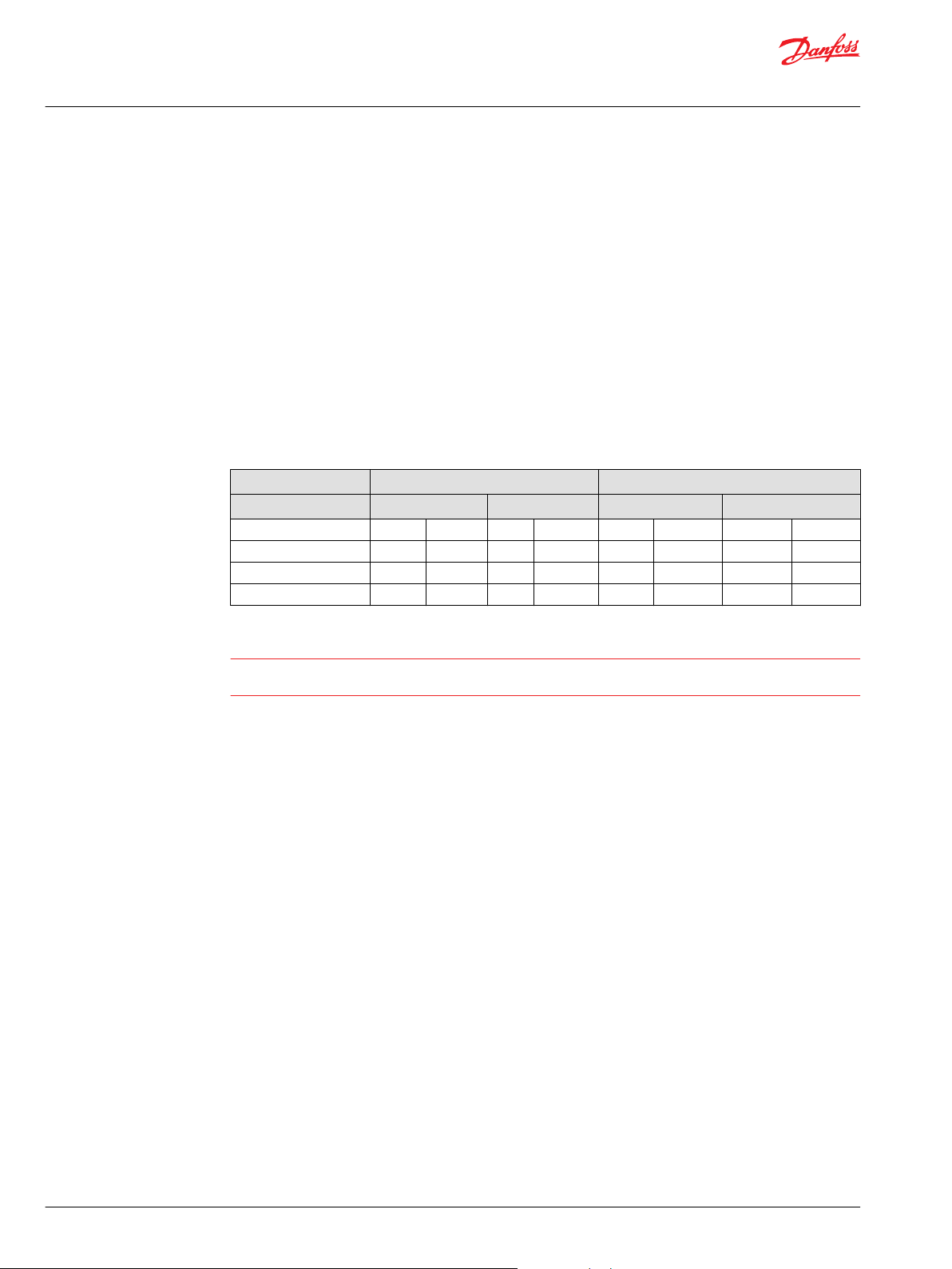
Input Shaft
The maximum allowable radial load (Re) is based on the maximum external moment (Me) and the
distance (L) from the mounting flange to the load. It is shown in the chart below.
Re = Me / L
Me Shaft moment
L Flange distance
Re External force to the shaft
Danfoss recommends clamp-type couplings for applications with radial shaft loads
Contact your Danfoss representative for an evaluation of unit bearing life if you have continuously
applied external loads exceeding 25 % of the maximum allowable radial load (Re) or the pump
swashplate is positioned on one side of center all or most of the time.
PTO shaft, Output shaft
Avoid any load in either direction.
©
Danfoss | May 2021 BC152886483777en-000301 | 17
Page 18

Technical Information
LDU20/24 Closed Circuit Axial Piston Transmission
System Design Parameters
Shaft Torque Rating and Spline Lubrication
Maximum torque ratings are based on torsional fatigue strength considering 100.000 full load reversing
cycles. However, a spline running in oil-flooded environment provides superior oxygen restriction in
addition to contaminant flushing. The rated torque of a flooded spline can increase to that of the
maximum published rating. A flooded spline would be indicative of a pump driven by a pump drive or
plugged into an auxiliary pad of a pump.
Maintaining a spline engagement at least equal to the Pitch Diameter will also maximize spline life. Spline
engagements of less than ¾ Pitch Diameter are subject to high contact stress and spline fretting.
Shaft Availability and Torque Ratings
Alignment between the mating spline’s pitch diameters is another critical factor in determining the
operating life of a splined drive connection. Plug-in, or rigid spline drive installations can impose severe
radial loads on the shaft. The radial load is a function of the transmitted torque and shaft eccentricity.
Increased spline clearance will not totally alleviate this condition; BUT, increased spline clearance will
prevent mechanical interference due to misalignment or radial eccentricity between the pitch diameters
of the mating splines. Maximize spline life by adding an intermediate coupling between the bearing
supported splined shafts.
18 | © Danfoss | May 2021 BC152886483777en-000301
Page 19

Technical Information
LDU20/24 Closed Circuit Axial Piston Transmission
System Design Parameters
Sizing Equations
The following equations are helpful when sizing hydraulic transmissions. Generally, the sizing process is
initiated by an evaluation of the machine system to determine the required transmission speed and
torque to perform the necessary work function. Refer to Selection of drive line components,
BC157786484430, for a more complete description of hydrostatic drive line sizing.
Based on SI units Based on US units
Input torque Nm [lbf•in]
Input power kW [hp]
Output
torque
Output
power
Where;
V
gp
V
gm
Δ
p
η
mp
η
mm
η
tp
η
tm
p
HD
p
ND
n
p
n
m
Nm [lbf•in]
kW [hp]
Pump displacement per rev. cm3 [in3]
Motor displacement per rev. cm3 [in3]
pHD – pND bar [psi]
Pump Mechanical-hydraulic (Torque) efficiency
Motor Mechanical-hydraulic (Torque) efficiency
Pump Overall efficiency
Motor Overall efficiency
High pressure bar [psi]
Low pressure bar [psi]
Input speed
Output speed
©
Danfoss | May 2021 BC152886483777en-000301 | 19
Page 20

Technical Information
LDU20/24 Closed Circuit Axial Piston Transmission
Model Code
Model Code: A - H
A - Displacement
Code Description
20D Displacement: 20 cc/rev / Block type : standard Block
24D Displacement: 24 cc/rev / Block type : standard Block
B - Rotation
Code Description
L Left hand side viewing from input shaft (CCW)
R Right hand side viewing from input shaft (CW)
C - Valve Plate
Code Description
A Standard
D - Control Arm Position
Code Description
L Left hand side viewing from input shaft (pump located upside)
R Right hand side viewing from input shaft (pump located upside)
E - Control Arm Configuration
Code Description
S Square
F - Pump Shaft Configuration (Input Shaft/PTO Shaft)
Code Description
JJ JIS 14T (Input) / JIS 14T (PTO)
AA ANSI 16/32-13T (Input) / ANSI 16/32-13T (PTO)
H - Output Shaft Configuration)
Code Description
J JIS 14T
A ANSI 16/32-13T
20 | © Danfoss | May 2021 BC152886483777en-000301
Page 21

Technical Information
LDU20/24 Closed Circuit Axial Piston Transmission
Model Code
Model Code: J - M
J - Centersection Configuration
Code Description
Drain port: 9.8mm on centersection
Charge port : 9.8mm on centersection
Without Bypass valve With Bypass valve on left
A X
B X
F X
H X
(A)
Connect charge inlet and drain line directly from LDU20 centersection with trans axle. See Installation Drawings
on page 27-30 for detail.
valve
(A)
(A)
Drain port: 3/4-16 drain port on housing
Charge port : 9/16-18 on centersection
Without Bypass valve With Bypass valve on left
side
K - Charge Pump Displacement
Code Description
N None
L - Charge Relief Setting
Code Description
07 7 bar at 10.8 l/min [102 psi at 2.9 US gal/min]
M - Bypass Valve
Code Description
N None
C w/Bypass Valve Left hand side
©
Danfoss | May 2021 BC152886483777en-000301 | 21
Page 22

Technical Information
LDU20/24 Closed Circuit Axial Piston Transmission
Model Code
Model Code: N - Z
N - Check & Relief Valve Side A
P - Check & Relief Valve Side B
The following two tables are used to selection for ports “A” and “B”
(Orifice must not be used for both side (A or B))
**N
14N
17N
21N
23N
25N
28N
30N
32N
34N
00N
1
Duty cycle analysis and Factory approval is needed. See Maximum Pressure in System Pressure on page 11.
**A
14A
17A
21A
25A
Check & Relief valve without orifice
140 bar [2030 psi]
175 bar [2538 psi]
210 bar [3045 psi]
230 bar [3285 psi]
250 bar [3625 psi]
280 bar [4060 psi]
300 bar [4351 psi]
1
325 bar [4713 psi]
1
345 bar [5003 psi]
Poppet type check valve
Check & Relief valve with orifice (∅0.85)
140 bar [2030 psi]
175 bar [2538 psi]
210 bar [3045 psi]
250 bar [3625 psi]
Y - Special Hardware Features
Code Description
NNN Housing Configuration : Standard
Z - Paint and Tag
Code Description
NNN No Paint (corrosion protection), Danfoss Logo
NAN No Paint (corrosion protection), Daikin Logo
BNN Black Paint, Danfoss Logo
BAN Black Paint, Daikin Logo
22 | © Danfoss | May 2021 BC152886483777en-000301
Page 23

[
0.778
]
±0.039
±0.039
±0.02
∅
19.75
0
-0.15
∅
19.75
0
-0.15
212
±1
30
±0.5
22
±0.5
34
±1
[
8.346
]
[
1.339
]
[
0.866
]
±0.02
[
1.181
]
-0.006
0
[
0.778
]
-0.006
0
Spline data
Number of teeth : 14
Module : 1.25
Pressure angle : 20°
Pitch diameter : 17.5
Addendum modification
Coefficient : 0.8
Involute spline
Per : JIS D 2001 CLASS a
Spline data
Number of teeth : 14
Module : 1.25
Pressure angle : 20°
Pitch diameter : 17.5
Addendum modification
Coefficient : 0.8
Involute spline
Per : JIS D 2001 CLASS a
full spline length
full spline length
P400012
±0.039
±0.02
[
7.913
]
[
0.787
]
Spline data
Number of teeth : 13
Pitch fraction : 16/32
Pressure angle : 30°
Pitch diameter : 20.638 [0.8125
]
Type of fit : Fillet root side
Per : ANSI B92.1-1970 CLASS
5
Spline data
Number of teeth : 13
Pitch fraction : 16/32
Pressure angle : 30°
Pitch diameter : 20.638 [0.8125
]
Type of fit : Fillet root side
Per : ANSI B92.1-1970 CLASS
5
∅
21.72
201
±1
20
±0.5
20
33
±1
±0.5
±0.09
∅
21.72
±0.09
±0.039
±0.02
[
1.299
]
[
0.787
]
±0.0035
[
0.855
]
±0.0035
[
0.855
]
full spline length full spline length
P400013
Technical Information
LDU20/24 Closed Circuit Axial Piston Transmission
Installation Drawings
Shaft Availability and Torque Ratings: Input Shaft/PTO Shaft
Input shaft/PTO Shaft
Option Spline
Torque Rating
N•m [lbf•in]
Rated Torque Maximum Torque
JJ 14 teeth, 1.25 module (Input) 122 [1080] 314 [2779]
14 teeth, 1.25 module (PTO) 89 [788] 310 [2743]
©
Danfoss | May 2021 BC152886483777en-000301 | 23
Option Spline
Torque Rating
N•m [lbf•in]
Rated Torque Maximum Torque
AA 13 theeth, 16/32 pitch (Input) 106 [938] 245 [2168]
13 theeth, 16/32 pitch (PTO) 106 [938] 226 [2000]
Page 24

21.5
±0.5
37
±1
∅
19.75
0
-0.15
±0.02
[
0.846
]
±0.039
[
1.457
]
[
0.778
]
-0.006
0
Spline data
Number of teeth : 14
Module : 1.25
Pressure angle : 20°
Pitch diameter : 17.5
Addendum modification
Coefficient : 0.8
Involute spline
Per : JIS D 2001 CLASS a
full spline length
P400014
∅
21.72
20 full spline length
±0.5
±0.09
36
±1
Spline data
Number of teeth : 13
Pitch fraction : 16/32
Pressure angle : 30°
Pitch diameter : 20.638 [0.8125
]
Type of fit : Fillet root side
Per : ANSI B92.1-1970 CLASS
5
±0.02
[
0.787
]
±0.039
[
1.417
]
±0.0035
[
0.855
]
P400015
Technical Information
LDU20/24 Closed Circuit Axial Piston Transmission
Installation Drawings
Shaft Availability and Torque Ratings: Output Shaft
Output Shaft
Option Spline
Torque Rating
N•m [lbf•in]
Rated Torque Maximum Torque
J 14 teeth, 1.25 module 87 [770] 310 [2743]
Option Spline
Torque Rating
N•m [lbf•in]
Rated Torque Maximum Torque
A 13 teeth, 20mm pitch 106 [938] 226 [2000]
24 | © Danfoss | May 2021 BC152886483777en-000301
Page 25

[ ]
[ ]
[ ]
[ ]
[ ]
[ ]
[ ]
[ ][ ]
[ ]
[ ]
[ ]
[ ]
[ ]
[ ]
[ ]
Charge gage (inlet) port "M3"
Port ISO 11926-1, 9/16-18
System B gage port "MB1"
Port ISO 11926-1, 3/4-16
System A gage port "MA1"
Port ISO 11926-1, 3/4-16
1.063
0.787
0.551
0.768
±0.003
±0.001
±0.008
±0.005
M8x1.25 Thread
16 [0.63] Min thread depth
[ ]
[ ]
[ ]
0.63
±0.003
0.394
0.965
R0.2
[ ]
4.280
[ ]
27
1.063
27
14
20
108.7 Max
∅
19.5
±0.08
∅
16
±0.08
R5
±0.13
10
±0.25
24.5
±0.2
Case drain port "L2"
Port ISO 11926-1, 3/4-16
High pressure
relief valve B
+0.0024
0.669
-0.0016
5.89
+0.0018
0
M10X1.5 Thread
CCW CW
18 [0.71] Min
Thread depth
X4
±0.016
18° MAX DISP.
18° MAX DISP.
95.6
57.5
42
2X 17
+0.06
-0.04
4X 45°
149.6
166.52 Max
55
+0.046
0
23.8
±0.4
1.654
3.764
2.264
[ ]
6.556
[ ]
2.165
[ ]
0.937[ ]
±0.016
23.8
±0.4
0.937[ ]
CW
Charge inlet port "S"
∅
9.8
±0.1
±0.0028
±0.002
+0.0014
0
±0.1
Depth 11
±0.004
±0.004
85
±0.07
102.8
±0.05
102.8
122
167.65
Max
69.15
Max
95.2 Max
86.2 Max
46 46
±0.05
∅
10
+0.036
0
1.811
±0.002
1.811
[ ]
4.047
4.803
6.600
[ ]
2.722
[ ]
3.394
[ ]
0.292
[ ]
2.286
[ ]
0.381
3.748
[ ]
95.2 Max
86.2 Max
3.394
[ ]
3.748
[ ]
3.346
4.047
0.394
[ ]
0.433
[ ]
0.386
[ ]
0.197
0
+0.016
163.52 Max
5
+0.4
0
40
6.438
[ ]
1.016
[ ]
CCW
CW
Case drain port "L3"
Control Arm Location (R)
See Model Code (Page 22)
∅
9.8
±0.1
±0.004
0.386
[ ]
∅
90
R11.5
R15
P400016
Technical Information
LDU20/24 Closed Circuit Axial Piston Transmission
Installation Drawings
Installation Drawings LDU20/24
©
Danfoss | May 2021 BC152886483777en-000301 | 25
Input shaft rotation CW CCW
Trunnion location Right
Trunnion rotation CW CCW CW CCW
Output rotation CCW CW CW CCW
High pressure port MA MB MB MA
Low pressure port MB MA MA MB
Page 26

[ ]
[ ]
[ ]
[ ]
[0.433 ]
System A gage port "MA2"
Port ISO 11926-1, 3/4-16
Control Arm Location (R)
System B gage port "MB2"
Port ISO 11926-1, 3/4-16
0.787
1.063
27
[ ]
1.063
27
20
Case drain port "L1"
Port ISO 11926-1, 3/4-16
High pressure
relief valve A
2.264
57.5
Approx.
center of
gravity
42
84.6
1.654
3.3
[ ]
CW
CCW
±0.008
±0.008
±0.008 ±0.008
71
±0.2
80
±0.2
25
±0.2
49
±0.2
4X ∅11
+0.38
-0.05
29.9
0.8
2.795
[ ]
3.15
[ ]
±0.008
±0.008
71
±0.2
80
±0.2
2.795
[ ]
3.15
[ ]
+0.015
-0.002
1.929
[ ]
0.984
[ ]
1.2
[ ]
0.03
[ ]
See Model Code (Page 22)
P400017
Technical Information
LDU20/24 Closed Circuit Axial Piston Transmission
Installation Drawings
26 | © Danfoss | May 2021 BC152886483777en-000301
Page 27
[
0.386
]
∅
9.8
±0.1
±0.004
[
0.386
]
∅
9.8
±0.1
±0.004
Case drain port "L3"
Charge inlet port "S"
Charge gage (inlet) port "M3"
Port ISO 11926-1, 9/16-18
Case drain port "L1, L2"
Port ISO 11926-1, 3/4-16
MA1
MB1
MA2
MB2
L1
L2
L3
S
M3
P400018
Technical Information
LDU20/24 Closed Circuit Axial Piston Transmission
Installation Drawings
Center section: Option A
Drain port: 9.8mm on centersection
Charge port: 9.8mm on centersection
©
Danfoss | May 2021 BC152886483777en-000301 | 27
Page 28

[
2.854
]
72.5
[
2.854
]
72.5
[
3.047
]
77.4
Charge inlet port "M3"
Port ISO 11926-1, 9/16-18
Case drain port "L1, L2"
Port ISO 11926-1, 3/4-16
MA1
MB1
MA2
MB2
L1
M3
L2
P400019
Technical Information
LDU20/24 Closed Circuit Axial Piston Transmission
Installation Drawings
Center section: Option B
Drain port: 3/4-16 on Housing.
Charge port: 9/16-18 on centersection
28 | © Danfoss | May 2021 BC152886483777en-000301
Page 29
Bypass valve
[
0.386
]
∅
9.8
±0.1
±0.004
[
0.386
]
∅
9.8
±0.1
±0.004
Case drain port "L3"
Charge inlet port "S"
[
1.339
]
34
[
0.709
]
(
17mm external hex
)
Torque 12 N•m [
9 lbf
•ft]
18
MA1
MB1
MA2
MB2
L1 L2
L3 M3S
Case drain port "L1, L2"
Port ISO 11926-1, 3/4-16
P400020
Technical Information
LDU20/24 Closed Circuit Axial Piston Transmission
Installation Drawings
Center section: Option F
Drain port: 9.8mm on centersection
Charge port: 9.8mm on centersection With Bypass valve
©
Danfoss | May 2021 BC152886483777en-000301 | 29
Page 30

[
]
Bypass valve
Case drain port "L1, L2"
Port ISO 11926-1, 3/4-16
Charge inlet port "M3"
Port ISO 11926-1, 9/16-18
0.709
18
1.339
34
[
]
MA1
MB1
MA2
MB2
L1 L2
M3
P400021
Technical Information
LDU20/24 Closed Circuit Axial Piston Transmission
Installation Drawings
Center section: Option H
Drain port: 3/4-16 on Housing
Charge port: 9/16-18 on centersection With Bypass valve
30 | © Danfoss | May 2021 BC152886483777en-000301
Page 31

Danfoss
Power Solutions GmbH & Co. OHG
Krokamp 35
D-24539 Neumünster, Germany
Phone: +49 4321 871 0
Danfoss
Power Solutions ApS
Nordborgvej 81
DK-6430 Nordborg, Denmark
Phone: +45 7488 2222
Danfoss
Power Solutions (US) Company
2800 East 13th Street
Ames, IA 50010, USA
Phone: +1 515 239 6000
Danfoss
Power Solutions Trading
(Shanghai) Co., Ltd.
Building #22, No. 1000 Jin Hai Rd
Jin Qiao, Pudong New District
Shanghai, China 201206
Phone: +86 21 2080 6201
Products we offer:
Hydro-Gear
www.hydro-gear.com
Daikin-Sauer-Danfoss
www.daikin-sauer-danfoss.com
Cartridge valves
•
DCV directional control
•
valves
Electric converters
•
Electric machines
•
Electric motors
•
Gear motors
•
Gear pumps
•
Hydraulic integrated
•
circuits (HICs)
Hydrostatic motors
•
Hydrostatic pumps
•
Orbital motors
•
PLUS+1® controllers
•
PLUS+1® displays
•
PLUS+1® joysticks and
•
pedals
PLUS+1® operator
•
interfaces
PLUS+1® sensors
•
PLUS+1® software
•
PLUS+1® software services,
•
support and training
Position controls and
•
sensors
PVG proportional valves
•
Steering components and
•
systems
Telematics
•
Danfoss Power Solutions is a global manufacturer and supplier of high-quality hydraulic and
electric components. We specialize in providing state-of-the-art technology and solutions
that excel in the harsh operating conditions of the mobile off-highway market as well as the
marine sector. Building on our extensive applications expertise, we work closely with you to
ensure exceptional performance for a broad range of applications. We help you and other
customers around the world speed up system development, reduce costs and bring vehicles
and vessels to market faster.
Danfoss Power Solutions – your strongest partner in mobile hydraulics and mobile
electrification.
Go to www.danfoss.com for further product information.
We offer you expert worldwide support for ensuring the best possible solutions for
outstanding performance. And with an extensive network of Global Service Partners, we also
provide you with comprehensive global service for all of our components.
Local address:
Danfoss can accept no responsibility for possible errors in catalogues, brochures and other printed material. Danfoss reserves the right to alter its products without notice. This also applies to products
already on order provided that such alterations can be made without subsequent changes being necessary in specifications already agreed.
All trademarks in this material are property of the respective companies. Danfoss and the Danfoss logotype are trademarks of Danfoss A/S. All rights reserved.
©
Danfoss | May 2021 BC152886483777en-000301
 Loading...