

Page 1
Service Manual
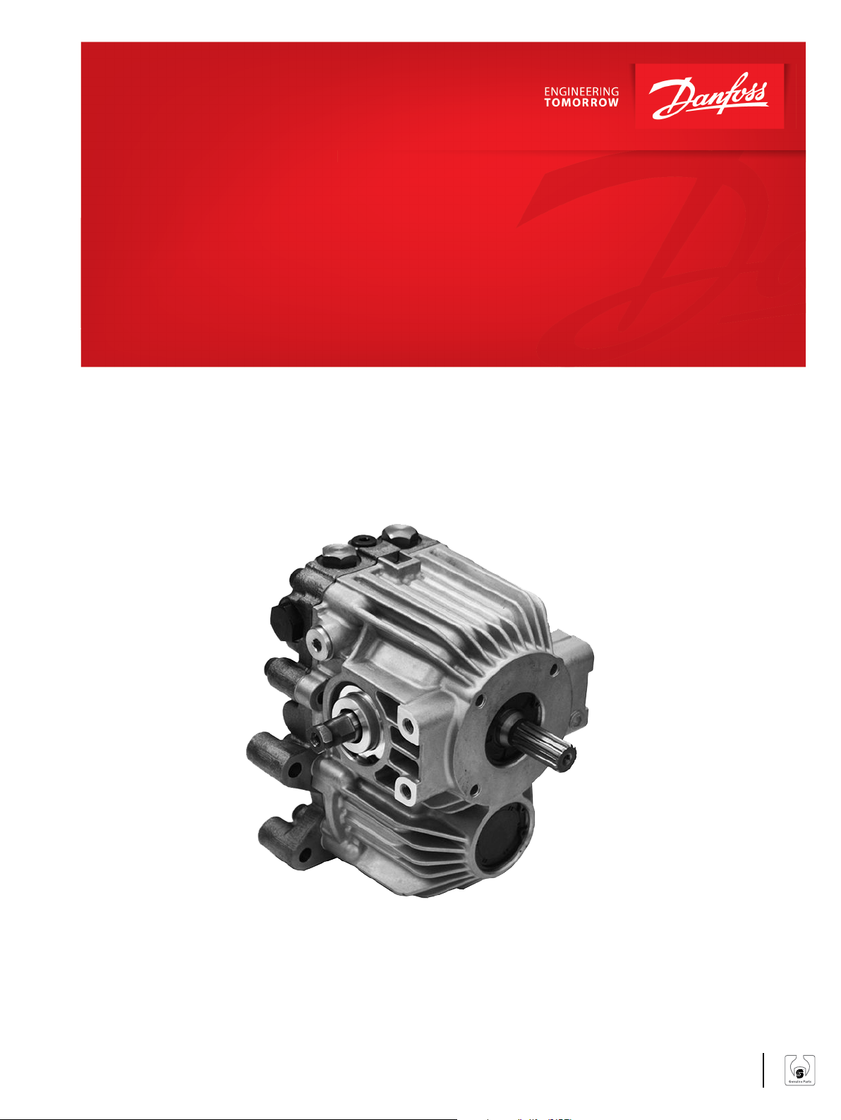
LDU20/24
Closed Circuit Axial Piston Transmission
www.danfoss.com
Page 2
Service Manual
LDU20/24 Closed Circuit Axial Piston Transmission
Revision history Table of revisions
Date Changed Rev
June 2021 Added Size 24, Changed document number from 'AX00000049' and '11071687' to
'AX152886481311'
July 2017 Updated to Engineering Tomorrow 0202
March 2014 Danfoss layout BA
January 2011 First edition AA
0304
2 | © Danfoss | June 2021 AX152886481311en-000304
Page 3

Service Manual
LDU20/24 Closed Circuit Axial Piston Transmission
Contents
Introduction
Overview..............................................................................................................................................................................................5
Warranty.............................................................................................................................................................................................. 5
General Instructions........................................................................................................................................................................ 5
Remove the unit.......................................................................................................................................................................... 5
Keep it clean..................................................................................................................................................................................5
Lubricate moving parts.............................................................................................................................................................5
Replace all O-rings and gaskets............................................................................................................................................. 5
Secure the unit.............................................................................................................................................................................6
Safety Precautions............................................................................................................................................................................6
Unintended machine movement..........................................................................................................................................6
Flammable cleaning solvents.................................................................................................................................................6
Fluid under pressure..................................................................................................................................................................6
Personal safety............................................................................................................................................................................. 6
Hazardous material.................................................................................................................................................................... 6
Symbols Used in Danfoss Literature..........................................................................................................................................7
General Description
Basic Design........................................................................................................................................................................................8
Key Features....................................................................................................................................................................................... 8
Typical Applications........................................................................................................................................................................ 8
Schematic Diagram..........................................................................................................................................................................8
Operation
HPRV (High Pressure Relief Valve) ............................................................................................................................................. 9
Charge Check Relief Valve with Orifice............................................................................................................................... 9
Bypass Function..............................................................................................................................................................................10
CPRV (Charge Pressure Relief Valve)....................................................................................................................................... 11
Control............................................................................................................................................................................................... 11
Direct Displacement Control................................................................................................................................................11
Control Handle Requirements............................................................................................................................................. 11
Operating Parameters
Overview........................................................................................................................................................................................... 12
Input Speed......................................................................................................................................................................................12
System Pressure..............................................................................................................................................................................12
Input Power......................................................................................................................................................................................12
Charge Pressure..............................................................................................................................................................................13
Case Pressure...................................................................................................................................................................................13
Viscosity.............................................................................................................................................................................................13
Temperature.................................................................................................................................................................................... 13
Technical Specifications
General Specifications..................................................................................................................................................................14
Physical Properties.........................................................................................................................................................................14
Operating Parameters..................................................................................................................................................................14
Fluid Specifications....................................................................................................................................................................... 15
Fluid and Filter Maintenance
Fluid and Filter Recommendations......................................................................................................................................... 16
Pressure Measurements
Port Locations and Gauge Installation...................................................................................................................................17
Initial Startup Procedure
Startup Procedure..........................................................................................................................................................................18
Troubleshooting
Overview........................................................................................................................................................................................... 19
System Operating Hot..................................................................................................................................................................19
Transmission Operates Normally in One Direction Only.................................................................................................19
System will not Operate in Either Direction.........................................................................................................................19
System Noise or Vibration...........................................................................................................................................................20
©
Danfoss | June 2021 AX152886481311en-000304 | 3
Page 4

Service Manual
LDU20/24 Closed Circuit Axial Piston Transmission
Contents
Sluggish System Response.........................................................................................................................................................20
Required Tools and Standard Procedures
Required Tools................................................................................................................................................................................ 21
Standard Procedures.................................................................................................................................................................... 21
Charge Check/HPRV Adjustments...........................................................................................................................................21
Checking for proper charge check/HPRV operation....................................................................................................21
Minor Repair
Shaft Seals.........................................................................................................................................................................................22
Removal........................................................................................................................................................................................22
Inspection....................................................................................................................................................................................22
Assembly......................................................................................................................................................................................22
Charge Check/HPRV......................................................................................................................................................................23
Removal........................................................................................................................................................................................23
Inspection....................................................................................................................................................................................23
Reassembly................................................................................................................................................................................. 23
Bypass Valve.....................................................................................................................................................................................24
Removal........................................................................................................................................................................................24
Inspection....................................................................................................................................................................................24
Reassembly................................................................................................................................................................................. 24
Torque Chart
Plug Size and Torque Chart........................................................................................................................................................25
4 | © Danfoss | June 2021 AX152886481311en-000304
Page 5

Service Manual
LDU20/24 Closed Circuit Axial Piston Transmission
Introduction
Overview
This manual includes information on the installation, maintenance, and minor repair of LDU20/24
transmission (HST). It includes a description of the unit and its individual components, troubleshooting
information, and minor repair procedures.
Performing minor repairs may require removal from the vehicle/machine. Thoroughly clean the unit
before beginning maintenance or repair activities. Since dirt and contamination are the greatest enemies
of any type of hydraulic equipment, follow cleanliness requirements strictly. This is especially important
when changing the system filter and when removing hoses or plumbing.
A worldwide network of Danfoss Authorized Service Centers is available for major repairs. Danfoss trains
and certifies Authorized Service Centers on a regular basis. You can locate your nearest Authorized
Service Center using the distributor locator at www.sauer-danfoss.com.
Warranty
Performing installation, maintenance, and minor repairs according to the procedures in this manual will
not affect your warranty. Major repairs requiring the removal of the units center section voids the
warranty unless completed by a Danfoss Global Service Partner.
General Instructions
Follow these general procedures.
Remove the unit
Prior to performing major repairs, remove the unit from the vehicle/machine. Chock the wheels on the
vehicle or lock the mechanism to inhibit movement. Be aware that hydraulic fluid may be under high
pressure and/or hot. Inspect the outside of the HST and fittings for damage. Cap hoses and plug ports
after removal to prevent contamination.
Keep it clean
Cleanliness is a primary means of assuring satisfactory HST life, on either new or repaired units. Clean the
outside of the HST thoroughly before disassembly. Take care to avoid contamination of the system ports.
Cleaning parts using a clean solvent wash and air drying is usually adequate.
As with any precision equipment, keep all parts free of foreign materials and chemicals. Protect all
exposed sealing surfaces and open cavities from damage and foreign material. If left unattended, cover
the transmission with a protective layer of plastic.
Lubricate moving parts
During assembly, coat all moving parts with clean hydraulic fluid. This assures that these parts are
lubricated during start-up.
Replace all O-rings and gaskets
Danfoss recommends you replace all O-rings, seals, and gaskets during repair.Lightly lubricate all O-rings
with clean petroleum jelly prior to assembly. Grease must be soluable in hydraulic fluid.
©
Danfoss | June 2021 AX152886481311en-000304 | 5
Page 6

W
W
W
W
W
Service Manual
LDU20/24 Closed Circuit Axial Piston Transmission
Introduction
Secure the unit
For major repair, place the unit in a stable position with the shaft pointing downward. It is necessary to
secure the transmission while removing and torquing components and fasteners.
Safety Precautions
Always consider safety precautions before beginning a service procedure. Protect yourself and others
from injury. Take the following general precautions whenever servicing a hydraulic system.
Unintended machine movement
Warning
Unintended movement of the machine or mechanism may cause injury to the technician or bystanders.
To protect against unintended movement, secure the machine or disable/disconnect the mechanism
while servicing.
Flammable cleaning solvents
Warning
Some cleaning solvents are flammable. To avoid possible fire, do not use cleaning solvents in an area
where a source of ignition may be present.
Fluid under pressure
Warning
Escaping hydraulic fluid under pressure can have sufficient force to penetrate your skin causing serious
injury and/or infection. This fluid may also be hot enough to cause burns. Use caution when dealing with
hydraulic fluid under pressure. Relieve pressure in the system before removing hoses, fittings, gauges, or
components. Never use your hand or any other body part to check for leaks in a pressurized line. Seek
medical attention immediately if you are cut by hydraulic fluid.
Personal safety
Warning
Protect yourself from injury. Use proper safety equipment, including safety glasses, at all times.
Hazardous material
Warning
Hydraulic fluid contains hazardous material. Avoid prolonged contact with hydraulic fluid. Always
dispose of used hydraulic fluid according to environmental regulations.
6 | © Danfoss | June 2021 AX152886481311en-000304
Page 7
Service Manual
LDU20/24 Closed Circuit Axial Piston Transmission
Introduction
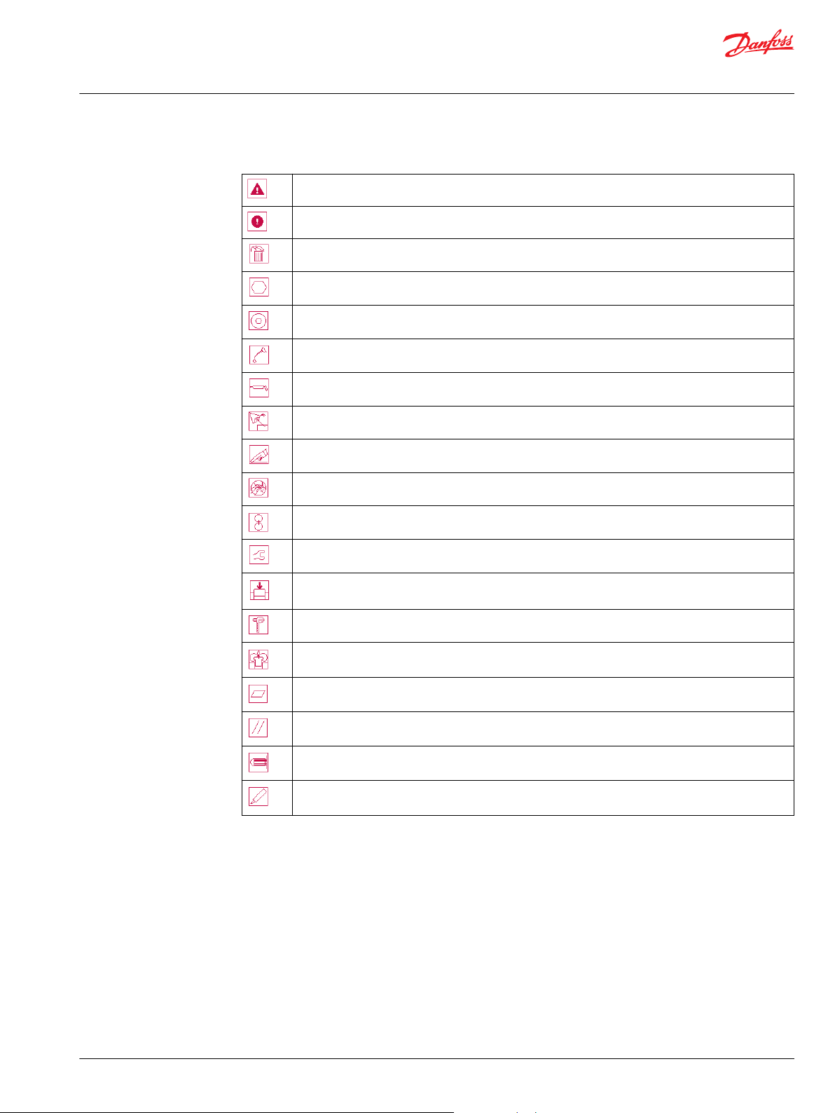
Symbols Used in Danfoss Literature
WARNING may result in injury
CAUTION may result in damage to product or property
Non-reusable part, use a new part
External hex head
Internal hex head
Lubricate with hydraulic fluid
Apply grease / petroleum jelly
Inspect for wear or damage
Clean area or part
Be careful not to scratch or damage
Note correct orientation
Torque specification
Press in – press fit
Measurement required
Pull out with tool – press fit
Flatness specification
Parallelism specification
Cover splines with installation cylinder
Mark orientation for reinstallation
The symbols above appear in the illustrations and text of this manual. They are intended to communicate
helpful information at the point where it is most useful to the reader. In most instances, the appearance
of the symbol itself denotes its meaning. The legend above defines each symbol and explains its purpose.
©
Danfoss | June 2021 AX152886481311en-000304 | 7
Page 8
MA1
MB1
MA2
MB2
L1
L2
L3
S
M3
P400004
Service Manual
LDU20/24 Closed Circuit Axial Piston Transmission
General Description
Basic Design
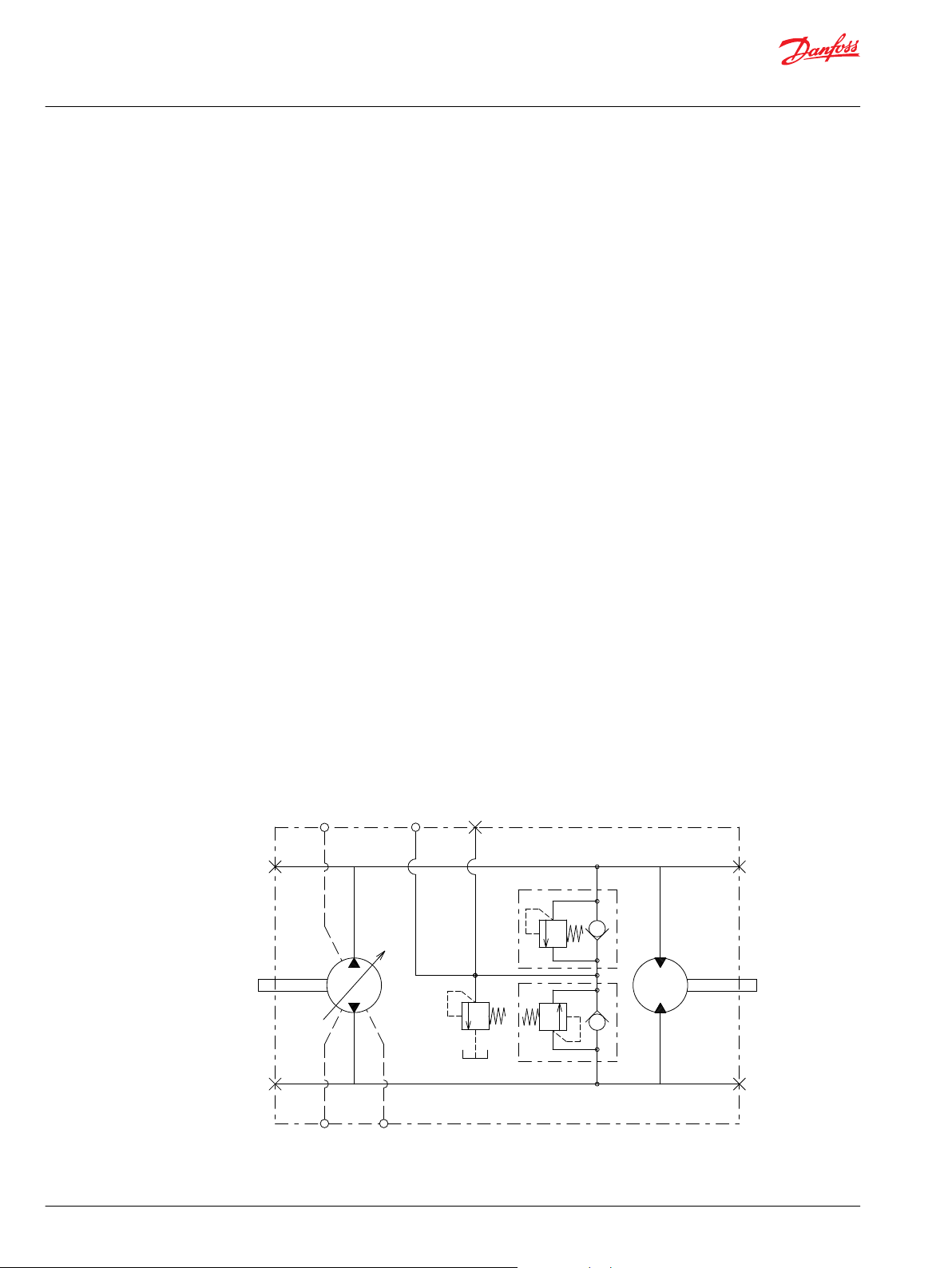
LDU20/24 is a U-style HST transmission, including a closed circuit variable displacement piston pump
with DDC (Direct displacement control) and a fixed motor. LDU20/24 is specially designed with optimized
performance, size, and cost, in order to fulfill the demand of the mobile applications marketplace. This
document provides the detailed specifications and features for LDU20/24.
Key Features
Easy to use design as Complete Hydrostatic Transmission package for Turf care machine & Compact
•
Utility Tractor of up to 26kw[35PS]
Compact design
•
U-style layout in One housing with Z-shaft configuration
•
Available external charge
•
Bypass valve for the pulling of the vehicle
•
Same shaft center distance as BDU21 85mm…Between pump and motor shaft
•
Same drive line design is available between BDU21 and LDU20/24
•
Best in class Efficiency by Female Piston & Male slipper design…Can reach approximately 80% overall
•
efficiency
Longer life kit, Higher Duty capability in most compact design in this class of HST
•
Low operating force
•
Serviced by a Worldwide Network of Danfoss
•
Typical Applications
Schematic Diagram
Compact utility tractor
•
Turf care
•
Small agricultural machinery
•
8 | © Danfoss | June 2021 AX152886481311en-000304
Page 9

P400005
C
Service Manual
LDU20/24 Closed Circuit Axial Piston Transmission
Operation
HPRV (High Pressure Relief Valve)
LDU20/24 is equipped with a combination high pressure relief and charge check valve. The high-pressure
relief function is a dissipative (with heat generation) pressure control valve for the purpose of limiting
excessive system pressures. The charge check function acts to replenish the low-pressure side of the
working loop with charge oil. Each side of the transmission loop has a dedicated HPRV valve that is nonadjustable with a factory set pressure. When system pressure exceeds the factory setting of the valve, oil
is passed from the high pressure system loop, into the charge gallery, and into the low pressure system
loop via the charge check.
The HST order code allows for different pressure settings to be used at each system port. HPRV valve with
orifice is available to gain wider neutral dead-band. When HPRV valves with orifice are used, it is only for
High pressure ports when vehicle goes in reverse. The system pressure order code for HST with only
HPRV is a reflection of the HPRV setting.
The system pressure order code for HST configured with pressure limiter and HPRV is a reflection of the
pressure limiter setting.
HPRV settings
HPRV valve without orifice 5 l/min [1.3 US gal/min]
HPRV valve with orifice 17 l/min [4.5 US gal/min]
HPRV (High Pressure Relief Valve)
Caution
HPRV´s are factory set at a low flow condition. Any application or operating condition which leads to
elevated HPRV flow will cause a pressure rise with flow above a valve setting. Consult factory for
application review.
Charge Check Relief Valve with Orifice
As an option, LDU20/24 offers a charge check relief valve with an orifice in order to enlarge the neutral
dead-band.
In some applications, it is desirable to use charge check valve with orifice for expanding null dead band,
giving both the safety measure to prevent the vehicle movement in the neutral position of the control
shaft and easy adjustment of neutral position when connected to vehicle linkage. The orifice connects
the working loop, which is a main hydraulic circuit, to a charge circuit. It always allows some internal
leakage to ensure the expanding null dead band around neutral position of control shaft. However, it
decreases the volumetric efficiency, particularly at high system pressure in the working loop. It is
recommended to install the orifice in a specific working loop, which is pressurized when the vehicle
moves in reverse. A cross section and characteristics are shown above. The charge check valves with
orifice are available with 0.85mm orifice today. This option is allowable for only high pressure port when
vehicle goes in reverse.
©
Danfoss | June 2021 AX152886481311en-000304 | 9
Page 10

C
System Pressure
Bypass Valve
System Pressure
P400006
Service Manual
LDU20/24 Closed Circuit Axial Piston Transmission
Operation
Bypass Function
The LDU20/24 contains a dedicated bypass valve option. The bypass function is activated when the
bypass valve is mechanically backed out 3 full turns (maximum). The bypass function allows a machine or
load to be moved without rotating the pump shaft or prime mover.
For example; an inoperable vehicle may need to be moved to the service or the repair location, or
winched onto a trailer without operating the prime mover.
Caution
Excessive speed or extended movement will damage the transmission.
Avoid excessive speeds and extended load/vehicle movement. Do not move the load or vehicle more
than 20 % of maximum speed or for longer than 3 minutes. When the bypass function is no longer
needed, reseat the bypass valve to the normal operating position.
Bypass Function
10 | © Danfoss | June 2021 AX152886481311en-000304
Page 11

Charge Flow
P400007
W
Service Manual
LDU20/24 Closed Circuit Axial Piston Transmission
Operation
CPRV (Charge Pressure Relief Valve)
The charge pressure relief valve maintains charge pressure at a designated level above case pressure. The
charge pressure relief valve is a direct acting poppet valve which opens and discharges fluid to the HST
case when pressure exceeds a designated level. For external charge flow the CPRV is set according to
below table. The charge pressure relief valve setting is specified on the model code of the transmission.
Charge Pressure Relief Valve settings
LDU20/24 10.8 l/min [2 US gal/min]
Charge Pressure Relief Valve Function
Flow l/min [US gal/min]
Control
Direct Displacement Control
The LDU20/24 features Direct Displacement Control (DDC) .The swashplate angle is set directly by a
control lever or linkage attached directly to the swashplate trunnion. Control lever movement changes
the speed and rotating direction of the motor by increasing or decreasing the swashplate angle.
The control input shaft is configurable on both of left and right hand side of the LDU20/24.
Control Handle Requirements
Maximum allowable trunnion torque is 79.1 N•m [700 lbf•in]. The approximate torque necessary to rotate
the control per 300 bar and 3000 rpm of system operating pressure is 25 N•m with standard valveplate.
The actual value will vary due to the influence of pump operating conditions. For mating dimensions, see
Installation drawings in LDU20/24 Technical Information Manual BC152886483777.
Warning
With no external forces applied to the swashplate trunnion, internal hydraulic forces may not return the
swashplate to the neutral position under all conditions of operation.
©
Danfoss | June 2021 AX152886481311en-000304 | 11
Page 12

W
Service Manual
LDU20/24 Closed Circuit Axial Piston Transmission
Operating Parameters
Overview
This section defines the operating parameters and limitations for LDU20/24 with regard to input speeds
and pressures. For actual parameters, refer to Operating Parameters in the Technical Specifications
section.
Input Speed
Minimum speed is the lowest input speed recommended during engine idle condition. Operating below
minimum speed limits pump’s ability to maintain adequate flow for lubrication and power transmission.
Rated speed is the highest input speed recommended at full power condition. Operating at or below
this speed should yield satisfactory product life.
Maximum speed is the highest operating speed permitted. Exceeding maximum speed reduces product
life and can cause loss of hydrostatic power and braking capacity. Never exceed the maximum speed
limit under any operating conditions.
Operating conditions between rated speed and maximum speed should be restricted to less than full
power and to limited periods of time. For most drive systems, maximum unit speed occurs during
downhill braking or negative power conditions.
Warning
System Pressure
Input Power
Unintended vehicle or machine movement hazard.
Exceeding maximum speed may cause a loss of hydrostatic drive line power and braking capacity. You
must provide a braking system, redundant to the hydrostatic transmission, sufficient to stop and hold the
vehicle or machine in the event of hydrostatic drive power loss.
System pressure is the differential pressure between system ports A and B. It is the dominant operating
variable affecting hydraulic unit life. High system pressure, which results from high load, reduces
expected life. Hydraulic unit life depends on the speed and normal operating, or weighted average,
pressure that can only be determined from a duty cycle analysis.
Maximum working pressure - is the highest recommended application pressure. Maximum working
pressure is not intended to be a continuous pressure. Propel systems with application pressures at, or
below, this pressure should yield satisfactory unit life given proper component sizing.
Maximum pressure is the highest allowable application pressure under any circumstance. Application
pressures above maximum working pressure will only be considered with duty cycle analysis and factory
approval. Minimum pressure must be maintained under all operating conditions to avoid cavitation.
All pressure limits are differential pressures referenced to low loop (charge) pressure.Subtract low loop
pressure from gauge readings to compute the differential.
Maximum continuous input power is the highest recommended input power to HST excluding PTO
output power.
12 | © Danfoss | June 2021 AX152886481311en-000304
Page 13

C
Service Manual
LDU20/24 Closed Circuit Axial Piston Transmission
Operating Parameters
Charge Pressure
An internal charge relief valve regulates charge pressure. Charge pressure maintains a minimum pressure
in the low side of the transmission loop. Charge pressure is the differential pressure above case pressure.
Minimum charge pressure is the lowest pressure safe working conditions allow in the system.
Maximum charge pressure is the highest charge pressure the charge relief adjustment allows, and
which provides normal component life.
Charge flow to transmission must be sufficient to provide adequate charge pressure.
Case Pressure
Do not exceed rated case pressure under normal operating conditions. During cold start, keep case
pressure below maximum intermittent case pressure. Size drain plumbing accordingly.
Caution
Possible component damage or leakage
Operation with case pressure in excess of stated limits may damage seals, gaskets, and/or housings,
causing external leakage. This condition may also affect performance since charge and system pressure
are referenced to case pressure.
Viscosity
Temperature
Maintain fluid viscosity within the recommended range for maximum efficiency and bearing life.
Minimum viscosity should only occur during brief occasions of maximum ambient temperature and
severe duty cycle operation. Maximum viscosity should only occur at cold start. Limit speeds until the
system warms up. Refer to Fluid specifications in LDU20/24 Technical Information Manual
BC152886483777.
Maintain fluid temperature within the limits shown in the Technical Specifications section of LDU20/24
Technical Information Manual BC152886483777. Minimum temperature relates to the physical properties
of the component materials. Cold oil will not affect the durability of the components, however, it may
affect the ability of the transmission to provide flow and transmit power. Maximum temperature is based
on material properties. Don't exceed it. Measure maximum temperature at the hottest point in the
system. Refer to Fluid Specifications in LDU20/24 Technical Information Manual BC152886483777.
Ensure fluid temperature and viscosity limits are concurrently satisfied.
©
Danfoss | June 2021 AX152886481311en-000304 | 13
Page 14

Service Manual
LDU20/24 Closed Circuit Axial Piston Transmission
Technical Specifications
General Specifications
Design U-style HST with variable displacement piston pump and fixed motor
Direction of Rotation Clockwise
Counterclockwise
Recommended Installation Position Discretionary: The housing must be filled with hydraulic fluid
Physical Properties
Features Units LDU20 LDU24
Displacement
Recommended charge pump displacement for external charge supply cm3/rev [in3/rev] 6 [0.37]
Torque at maximum displacement (theoretical)
Mass moment of inertia of
rotating components
Weight dry kg [lb] 14.1 [31.1]
Oil volume
1
Max Swash angle is 18 deg.
Pump side
Motor side 20 [1.22] 24 [1.46]
Pump side
Motor side 0.000928 [0.000683]
Case only
With passage 1.2 [0.32]
1
cm3/rev [in3/rev]
N•m/bar [lbf•in/1000 psi]
kg•m2 [slug•ft2]
liter [US gal]
0-20 [0-1.22] 0-24 [0-1.46]
0.32 [195.2] 0.38 [234.2]
0.000936 [0.000693]
1.1 [0.28]
Operating Parameters
Features Units LDU20 LDU24
Minimum for external charge supply
Input speed
System pressure
Input power Maximum kw [PS] 22 [30] 26 [35]
Charge pressure Minimum bar [psi] 5 [73]
Case pressure
Minimum for full performance 1300
Rated 3400
Maximum 3800
Maximum working pressure
Maximum pressure 345 [500]
Rated
Maximum 3 [43.5]
min-1 (rpm)
bar [psi]
bar [psi]
500
300 [4350]
1 [14.5]
14 | © Danfoss | June 2021 AX152886481311en-000304
Page 15

Service Manual
LDU20/24 Closed Circuit Axial Piston Transmission
Technical Specifications
Fluid Specifications
Features Units LDU20/24
Viscosity Minimum mm2/sec. [ SUS] 7 [49]
Recommended range 12-60 [66-280]
Maximum 1600 [7500]
Temperature Minimum Degrees C [Degrees F] -40 [-40]
Recommended range +82 [+180]
Maximum +104 [+220]
Filtration (recommended minimum) Cleanliness per ISO 4406 22/18/13
Efficiency (charge pressure filtration) b - ratio b 15-20=75(b 10≥10)
Efficiency (suction and return line
filtration)
Rercommended inlet screen mesh
size
µm 100-125
b 15-20=75(b 10≥10)
©
Danfoss | June 2021 AX152886481311en-000304 | 15
Page 16

C
W
Service Manual
LDU20/24 Closed Circuit Axial Piston Transmission
Fluid and Filter Maintenance
Fluid and Filter Recommendations
To ensure optimum life, perform regular maintenance of the fluid and filter. Contaminated fluid is the
main cause of unit failure. Take care to maintain fluid cleanliness when servicing.
Check the reservoir daily for proper fluid level, the presence of water, and rancid fluid odor. Fluid
contaminated by water may appear cloudy or milky or free water may settle in the bottom of the
reservoir. Rancid odor indicates the fluid has been exposed to excessive heat. Change the fluid
immediately if these conditions occur. Correct the problem immediately.
Inspect vehicle for leaks daily.
Change the fluid and filter per the vehicle/machine manufacturer's recommendations or at these
intervals.
We recommend first fluid change occur at 500 hours of operation.
Fluid and Filter Change Interval
Reservoir Type Max. Oil Change Interval
Sealed 2000 Hours
Breather 500 Hours
Caution
High temperatures and pressures accelerate fluid aging. This may require more frequent fluid changes.
Change the fluid more frequently if it becomes contaminated with foreign matter (dirt, water, grease,
etc.) or if the fluid is subjected to temperature levels greater than the recommended maximum. Dispose
of used hydraulic fluid properly. Never reuse hydraulic fluid.
Change filters when changing fluid or when the filter indicator directs. Replace all fluid lost during filter
change
Warning
Hydraulic fluid contains hazardous material. Avoid contact with hydraulic fluid. Always dispose of used
hydraulic fluid according to state, and federal environmental regulations. Never reuse hydraulic fluid.
16 | © Danfoss | June 2021 AX152886481311en-000304
Page 17

M3
L1
L2 (REVERSE SIDE)
P108517
MB1
MB2
(REVERSE SIDE)
MA1
MA2
(REVERSE SIDE)
Service Manual
LDU20/24 Closed Circuit Axial Piston Transmission
Pressure Measurements
Port Locations and Gauge Installation
The following table and drawing show the port locations and gauge sizes needed.
Port Information
Port Identifier Port Size Wrench Size Pressure Obtained Gauge Size, bar [psi]
L1, L2 3/4-16 UNF 5/16 internal hex Case Drain 10 [100]
MA1, MA2, MB1, MB2 3/4-16 UNF 7/8 hex wrench System Pressure 500 [5000]
M3 9/16-18 UNF 1/4 internal hex Charge Pressure 50 [1000]
Port Locations
©
Danfoss | June 2021 AX152886481311en-000304 | 17
Page 18

W
C
Service Manual
LDU20/24 Closed Circuit Axial Piston Transmission
Initial Startup Procedure
Startup Procedure
Always follow this procedure when starting up a new LDU20/24 installation or when the transmission has
been removed.
Warning
This service procedure may require disabling a vehicle/machine (raising the wheels off the ground, or
disconnecting the work function) to prevent injury to the technician and bystanders. Take the necessary
safety precautions.
1. Before installing the transmission, inspect the units for possible damage incurred during shipping
and handling.
2. Make certain all system components (reservoir, hoses, valves, fittings, heat exchanger, and so forth)
are clean before filling with fluid.
3. Install new system filter element(s) if necessary. Check that inlet line fittings are properly tightened
and free of air leaks.
4. Install the transmission. Install a 50 bar [1000 psi] gauge in the charge pressure gauge port M3.
5. Fill the housing by adding filtered hydraulic fluid to the upper case drain port.
6. Fill the reservoir with hydraulic fluid of the recommended type and viscosity. Use a 10-micron filler
filter. Ensure construction plug is closed after filling is complete.
7. Place the control lever in neutral, The control linkage must be disconnected from the transmission
during initial start up.
Caution
After start-up the fluid level in the reservoir may drop due to system components filling with fluid.
Damage to hydraulic components may occur if the fluid supply runs out. Ensure reservoir remains full
of fluid during start-up.
Air entrapment in oil under high pressure may damage hydraulic components. Check carefully for
inlet line leaks.
Do not run at maximum pressure until system is free of air and fluid has been thoroughly filtered.
8. Use a common method to disable the engine to prevent it from starting. Crank the starter for several
seconds. Do not to exceed the engine manufacturer's recommendation. Wait 30 seconds and then
crank the engine a second time as stated above. This operation helps remove air from the system
lines. Refill the reservoir to recommended full oil level.
9. When the gauge begins to register charge pressure, enable and start engine. Let the engine run for a
minimum of 30 seconds at low idle to allow the air to work itself out of the system. Check for leaks at
all line connections and listen for cavitation. Check for proper fluid level in reservoir.
10. When adequate charge pressure is established (as shown in model code), increase engine speed to
normal operating rpm to further purge residual air from the system.
11. Shut the off engine. Connect the control linkage. Start the engine, checking to be certain the pump
remains in neutral. Run the engine at normal operating speed and carefully check for forward and
reverse control operation.
12. Continue to cycle between forward and reverse for at least 5 minutes to bleed all air and flush system
contaminants out of the system loop.
Charge pressure may decrease slightly during forward or reverse operation.
13. Check that the reservoir is full. Remove charge pressure gauge and cap charge pressure port (M3).
The transmission is now ready for operation.
18 | © Danfoss | June 2021 AX152886481311en-000304
Page 19

Service Manual
LDU20/24 Closed Circuit Axial Piston Transmission
Troubleshooting
Overview
This section provides general steps to follow if you observe undesirable system conditions. Follow the
steps listed until you solve the problem. Some of the items are system specific. We reference the section
in this manual of more information is available. Always observe the safety precautions listed in the
Introduction section and any precautions related to your specific equipment.
System Operating Hot
Item Description Action
Oil level in reservoir. Insufficient hydraulic fluid does not meet
cooling demands of system.
Heat exchanger. Heat exchanger is not sufficiently cooling
the system.
Bypass valve Leakage through by-pass line with high speed operation
may cause temperature increase
System relief pressure
settings
System pressure. Frequent or long term operation over system relief setting
If the system relief valves are worn, contaminated, or valve
settings are too low, the relief valves get overworked.
creates heat in system.
Fill reservoir to proper level.
Check air flow and input air temperature
for heat exchanger. Clean, repair or
replace heat exchanger.
Inspect bypass valve and replace as necessary. Check that
bypass valve is tightened.
Verify settings of high pressure relief valves
and adjust or replace as necessary.
Measure system pressure. If pressure
is too high, reduce loads.
Transmission Operates Normally in One Direction Only
Item Description Action
Control linkage Control linkage is operating improperly. Repair/replace linkage
Interchange charge check/
HPRVs
Bypass valve is open Open bypass valve will cause either direction to be
Interchanging the charge check/HPRVs will show if the
problem is related to the valve function.
inoperative
If the problem changes direction, replace the defective
valve.
Close/repair bypass function
System will not Operate in Either Direction
Item Description Action
Oil level in reservoir Insufficient hydraulic fluid to supply system loop. Fill reservoir to proper level.
Bypass valve is open If bypass valve is open, the system loop becomes
depressurized.
Charge pressure with pump
in neutral
System pressure Low system pressure does not provide enough power to
Charge check/HPRVs Low system pressure does not provide enough power to
Control linkage Linkage operating improperly. Repair/replace linkage
Low charge pressure insufficient to recharge system loop Measure charge pressure with the pump in neutral. If
move load.
move load.
Close bypass valve
pressure is low, go to next step.
Measure system pressure. Continue to next step.
Repair or replace charge check/HPRVs
©
Danfoss | June 2021 AX152886481311en-000304 | 19
Page 20

Service Manual
LDU20/24 Closed Circuit Axial Piston Transmission
Troubleshooting
System Noise or Vibration
Item Description Action
Reservoir oil level Low oil level leads to cavitation. Fill reservoir.
Aeration of the oil/charge
inlet vacuum
Cold oil If oil is cold, it may be too viscous for proper function and
Charge inlet vacuum High inlet vacuum causes noise/cavitation. Check that inlet line is not restricted and is proper size.
Shaft couplings A loose shaft coupling causes excessive noise. Replace loose shaft coupling.
Shaft alignment Misaligned HST and prime mover shafts create noise. Align shafts.
Charge check/HPRVs Unusual noise may indicate sticking valves. Possible
Sluggish System Response
Item Description Action
Oil level in reservoir Low oil level causes sluggish response. Fill reservoir.
Charge check/HPRVs Incorrect pressure settings affects system reaction time. Replace charge check/HPRVs
Low prime mover speed Low engine speed reduces system performance Adjust engine speed.
Air in system Air in system produces sluggish system response Fill tank to proper level. Cycle system slowly for several
Charge inlet vacuum Inlet vacuum is too high resulting in reduced system
Control linkage Linkage operating improperly Repair or replace control linkage
Air in the system decreases efficiency of units and controls.
Air in the system is indicated by excessive noise in HST,
foaming in oil, and hot oil.
pump cavitates
contamination.
pressure.
Find location where air is entering into the system and
repair. Check that inlet line is not restricted and is proper
size.
Allow the oil to warm up to its normal operating
temperature with engine at idle speed.
Check filter.
Clean/replace valves and test the unit.
minutes to remove air from system.
Measure charge inlet vacuum. Inspect line for proper sizing.
Replace filter. Confirm proper bypass operation.
20 | © Danfoss | June 2021 AX152886481311en-000304
Page 21

C
C
Service Manual
LDU20/24 Closed Circuit Axial Piston Transmission
Required Tools and Standard Procedures
Required Tools
The service procedures described in this manual can be performed using common mechanic's hand
tools. Special tools, if required, are shown. When testing system pressure, calibrate pressure gauges
frequently to ensure accuracy. Use snubbers to protect gauges.
Standard Procedures
Caution
Contamination can damage internal components and void the warranty. Take precautions to ensure
system cleanliness when removing and reinstalling system lines.
1. With the prime mover off, thoroughly clean all dirt and grime from the outside of the transmission.
Ensure the surrounding areas are clean and free of contaminants such as dirt and grime.
2. If removing the transmission, tag each hydraulic line connected to the transmission. If you disconnect
hydraulic lines, plug each open port to keep dirt and contamination out of the transmission.
3. Inspect the system for contamination. Look at the hydraulic fluid for signs of system contamination,
such as oil discoloration, foam in the oil, sludge, or small metal particles.
4. Remove the transmission.
5. Perform transmission function test.
6. Before re-installing the transmission on the machine, test for leaks , drain the system, flush all lines,
Charge Check/HPRV Adjustments
The Charge Check/HPRV combines the charge check and high pressure relief functions. Whenever you
replace a Charge Check/HPRV, operate the vehicle/machine through its full range of functions to ensure
proper HST operation. The Charge Check/HPRVs are preset at the factory. No adjustment is possible.
Checking for proper charge check/HPRV operation
If you suspect Charge Check/HPRV malfunction, swap valves and test operation. If the symptoms switch
direction, replace the faulty valve.
Caution
Be careful not to damage solenoids and electrical connections when using straps or chains to remove
transmission from machine.
replace all filters, and fill with new hydraulic fluid.
©
Danfoss | June 2021 AX152886481311en-000304 | 21
Page 22

P108 483E
F115
F125
H115
H125
F215
P108 165E
F210
H215
H210
Service Manual
LDU20/24 Closed Circuit Axial Piston Transmission
Minor Repair
Shaft Seals
Removal
1. Using a snap ring pliers, remove retaining ring (F125, F215, H125, H215).
2. Use a slide-hammer style puller to remove seal (F115, F210, H115, H210). Be careful not to damage
the shaft or seal bore when removing the seal. Discard seal.
Inspection
Inspect retaining ring for wear or damage.
Assembly
1. Lubricate inside diameter of new seal. Cover the shaft splines with protective sleeve to avoid
damaging the seal during installation.
2. Using a seal installation tool, start the seal into the housing bore. Hand press the seal the rest of the
way into the housing bore. Ensure the seal clears the retaining ring groove in the housing. Remove
the protective sleeve from the shaft.
Do not press seal beyond snap ring groove. Stop pressing just when you have room to install the
retaining ring into the bore.
3. Using a snap ring pliers, install retaining ring (F125, F215, H125, H215).
Shaft Seals
22 | © Danfoss | June 2021 AX152886481311en-000304
Page 23

P108 167E
78.4 Nm
[58 lbf-ft]
78.4 Nm
[58 lbf-ft]
N120
24 mm
N130
N100
N110
P120
24 mm
P130
P100
P110
Service Manual
LDU20/24 Closed Circuit Axial Piston Transmission
Minor Repair
Charge Check/HPRV
The high pressure relief and charge check valve assembly may be removed for cleaning and replacement
of the O-rings. These valves are factory set and are not field adjustable. Refer to the transmission model
code for the factory setting when ordering replacements.
Removal
1. Using an 24 mm hex wrench, remove the valve seat plugs (N120, P120).
2. Carefully lift the valve (N110, P110) and spring (N100, P100) assemblies from the center section using
a magnet.
Inspection
Inspect the valves and mating seats in the valve seat plugs (N120, P120) for damage or foreign material.
Reassembly
1. Lubricate and install new O-rings (N130, P130) on valve seat plug (N120, P120).
2. Verify that the conical springs (N100, P100) are properly retained on the check relief valves (N110,
P110). Install the valve assemblies into the center section. Ensure each valve assembly moves freely in
its bore.
3. Install the valve seat plugs into the center section and torque to 78.4 N•m [58 lbf•ft].
4. Operate vehicle/machine through full range of controls to ensure proper operation. Check for leaks.
Charge Check/HPRV
©
Danfoss | June 2021 AX152886481311en-000304 | 23
Page 24

P108 166E
12 Nm
[9 lbf-ft]
M100
17 mm
M110
M120
M130
Service Manual
LDU20/24 Closed Circuit Axial Piston Transmission
Minor Repair
Bypass Valve
Removal
Using a 17mm hex wrench, remove the bypass valve cartridge. Discard O‑ring (M110, M130) and backup
ring (M120).
Inspection
Inspect cartridge. Replace as necessary.
Reassembly
1. Lubricate and install new O-ring (M110, M130) and backup ring (M120) onto cartridge.
2. Install the bypass valve cartridge using a 17mm hex wrench. Torque to
12 N•m [9lbf•ft].
Bypass Valve
24 | © Danfoss | June 2021 AX152886481311en-000304
Page 25

J400
J200
J250
J300
J350
L1
L2
(REVERSE SIDE)
Y300
Y300
P108482
MB1
M3
MA1
MB2
MA2
(REVERSE SIDE)
(REVERSE SIDE)
Service Manual
LDU20/24 Closed Circuit Axial Piston Transmission
Torque Chart
Plug Size and Torque Chart
Item O-ring Plug Wrench Size Torque N•m [lbf•ft]
J200, J250, J300, J350 3/4-16 UNF 7/8 hex wrench 78.4 [57.8]
J400 9/16-18 UNF 1/4 internal hex 35 [25.8]
Y300 3/4-16 UNF 5/16 internal hex 39.2 [29]
Plugs
©
Danfoss | June 2021 AX152886481311en-000304 | 25
Page 26

Danfoss
Power Solutions GmbH & Co. OHG
Krokamp 35
D-24539 Neumünster, Germany
Phone: +49 4321 871 0
Danfoss
Power Solutions ApS
Nordborgvej 81
DK-6430 Nordborg, Denmark
Phone: +45 7488 2222
Danfoss
Power Solutions (US) Company
2800 East 13th Street
Ames, IA 50010, USA
Phone: +1 515 239 6000
Danfoss
Power Solutions Trading
(Shanghai) Co., Ltd.
Building #22, No. 1000 Jin Hai Rd
Jin Qiao, Pudong New District
Shanghai, China 201206
Phone: +86 21 2080 6201
Products we offer:
Hydro-Gear
www.hydro-gear.com
Daikin-Sauer-Danfoss
www.daikin-sauer-danfoss.com
Cartridge valves
•
DCV directional control
•
valves
Electric converters
•
Electric machines
•
Electric motors
•
Gear motors
•
Gear pumps
•
Hydraulic integrated
•
circuits (HICs)
Hydrostatic motors
•
Hydrostatic pumps
•
Orbital motors
•
PLUS+1® controllers
•
PLUS+1® displays
•
PLUS+1® joysticks and
•
pedals
PLUS+1® operator
•
interfaces
PLUS+1® sensors
•
PLUS+1® software
•
PLUS+1® software services,
•
support and training
Position controls and
•
sensors
PVG proportional valves
•
Steering components and
•
systems
Telematics
•
Danfoss Power Solutions is a global manufacturer and supplier of high-quality hydraulic and
electric components. We specialize in providing state-of-the-art technology and solutions
that excel in the harsh operating conditions of the mobile off-highway market as well as the
marine sector. Building on our extensive applications expertise, we work closely with you to
ensure exceptional performance for a broad range of applications. We help you and other
customers around the world speed up system development, reduce costs and bring vehicles
and vessels to market faster.
Danfoss Power Solutions – your strongest partner in mobile hydraulics and mobile
electrification.
Go to www.danfoss.com for further product information.
We offer you expert worldwide support for ensuring the best possible solutions for
outstanding performance. And with an extensive network of Global Service Partners, we also
provide you with comprehensive global service for all of our components.
Local address:
Danfoss can accept no responsibility for possible errors in catalogues, brochures and other printed material. Danfoss reserves the right to alter its products without notice. This also applies to products
already on order provided that such alterations can be made without subsequent changes being necessary in specifications already agreed.
All trademarks in this material are property of the respective companies. Danfoss and the Danfoss logotype are trademarks of Danfoss A/S. All rights reserved.
©
Danfoss | June 2021 AX152886481311en-000304
 Loading...