

Page 1
Data sheet
k
Flame sensors
LD/LDS
Description Danfoss LD/LDS sensors are used to detect
the flame in yellow flame oil burners. They are
designed for use with Danfoss units of the OBC
80 and BHO 70 series.
LD/LDS sensors meet the requirements of the
EN298:2012 standard, as well as those of the
RoHS and WEEE Directives.
Function The LD/LDS sensors are based on the photo
transistor principle in connection with an
amplifier and convert light from the flame into
a current. The flame’s characteristics and the
location of the sensor influence the size of the
photo current created in LD/LDS. For this reason,
LD/LDS is available in two sensitivity levels.
If a strong enough signal is not produced with
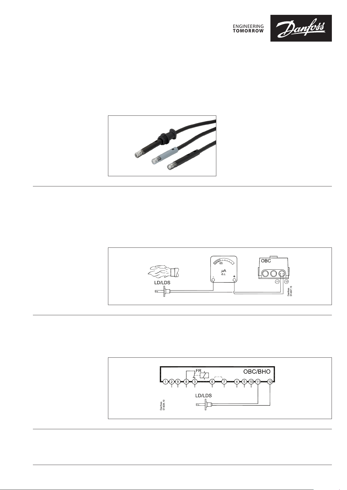
Electrical connection The LD/LDS sensors connect to Danfoss units of
the OBC 80 and BHO 70 series as shown in the
diagram.
the selected sensor, select a sensor with a higher
sensitivity level. If the flame cannot be detected
at the highest level of sensitivity, use the Danfoss
UV sensor.
To determine the signal’s quality, use the gauge
set-up below.
For no flame/darkness, the value must be ≤ 5 μA;
for flame/light the value must be ≥65 μA.
Please note that the blue wire must be
connected to terminal 11, and may not be
connected to the common 0 terminal (2) or
the appertaining auxiliary terminal in the base
section.
Blue Blac
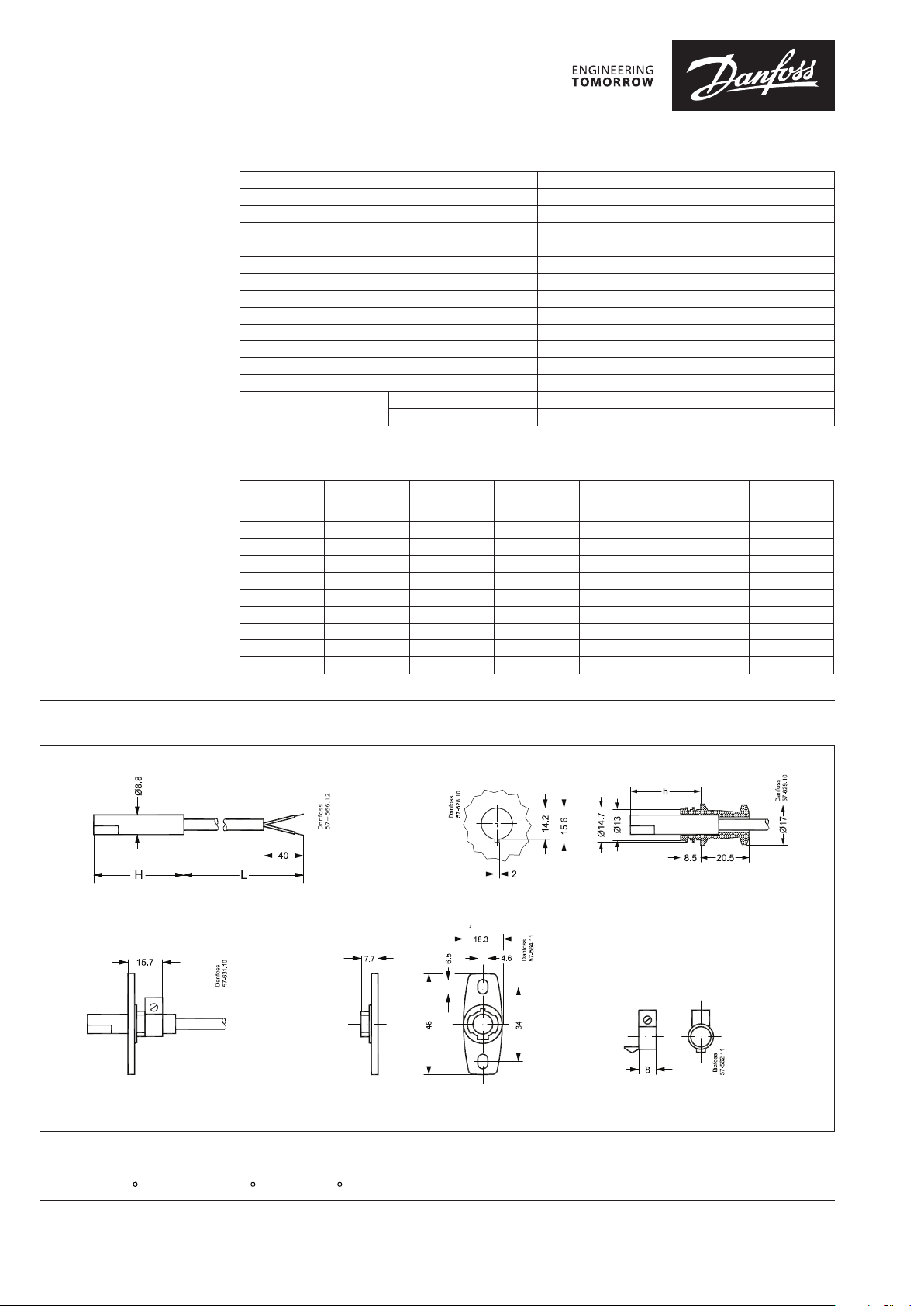
Installation The LD/LDS sensors can be installed using a
flange and clamping ring; alternatively, use a
rubber sleeve (delivered mounted on LD/LDS).
© Danfoss | 2018.07 VD.AU.B2.02 | 1
The sensors are available in two standard
lengths, with a longer piece featuring built-in
extension tubes.
Page 2
Danfos
produc
Al
Danfoss A/S
Heating Segment
Data sheet Flame sensors LD/LDS
057H7071
057H7072
Technical Data
Ordering
Standard program
Characteristics Data
Rated voltage 230V ac
Operating range 195-253 V ac
Frequency 50-60 Hz
Enclosure IP 40
Installation Any position
Flame sensor measuring condition 12V dc +/- 2% with Ri=100 Kohm +/- 2%
Signal output Max. 85 µA
Recomended signal output (light) ≥ 65 µA
Flame signal for no light (dark) ≤ 5 µA
Ambient temperature operation -20 to + 70°C
Ambient temperature transport -30 to + 70°C
Weight See table
Wiring OBC 80/ BHO 70
Typ e
LD 2000 65.5 Normal Black 94 057H7105
LD 800 65.5 Normal Black 41 0 57H7106
LD 500 50.0 Normal Black 26 057H 7107
LDS 500 50.0 High Blue 26 057H710 8
LDS 600 65.5 High Blue 32 057H710 9
LDS 350 105.0 High Blue 22 0 57H 7110
LDS 800 65.5 High Blue 41 05 7H7 111
Flange - - - - 3 057H7071
Clamping ring - - - - 1 057H7072
Cable length
L
(mm)
Blue wire, neutral Terminal 11
Black wire, signal Terminal 12
House length
H
(mm)
Sensitivity
Colour of
house
Weight
(g)
Code no.
Dimensions
s can accept no responsibility for possible errors in catalogues, brochures and o ther printed material. Danfoss reserves the right to alter its pro ducts without notice. This also applies to
ts already on order provided that such alterations can be m ade without subsequential changes being necessary in specications already agreed.
l trademarks in this material are property of the r espective companies. Danfoss and all Danfoss logot ypes are trademarks of Danfoss A/S. All rights reserved.
• heating.danfoss.com • +45 7488 2222 • E-Mail: heating@danfoss.com
© Danfoss | DHS-SRMT/SI | 2018.072 | VD.AU.B2.02
 Loading...