

Page 1
Data Sheet
Thermostat
Type KP
The KP Thermostats are single-pole, doublethrow (SPDT) temperature-operated electric
switches.
They can be connected directly to a singlephase AC motor of up to approx. 2 kW or
installed in the control circuit of DC motors and
large AC motors.
The KP Thermostats are used for regulation, but
can also be seen in safety monitoring systems.
They are available with vapour charge or with
adsorption charge. With vapour charge the
dierential is very small. The KP Thermostats
with adsorption charge are widely used to give
frost protection.
Features
• Wide regulating range
• Can be used for deep freeze, refrigeration and
air conditioning plant
• Welded bellows elements mean increased
reliability
• Small dimensions. Easy to install in
refrigerated counters or cold rooms
• Ultra-short bounce times. This gives long
operating life, reduces wear to a minimum
and increases reliability
• Standard versions with changeover switch.
Possible to obtain opposite contact function
or to connect a signal
• Electrical connection at the front of the unit.
◦ Facilitates rack mounting
◦ Saves space
• Suitable for alternating and direct current
• Cable entry of soft thermoplastic for cables
from 6 to 14 mm diameter
• Extensive and wide range
AI203586420959en-000801
Page 2
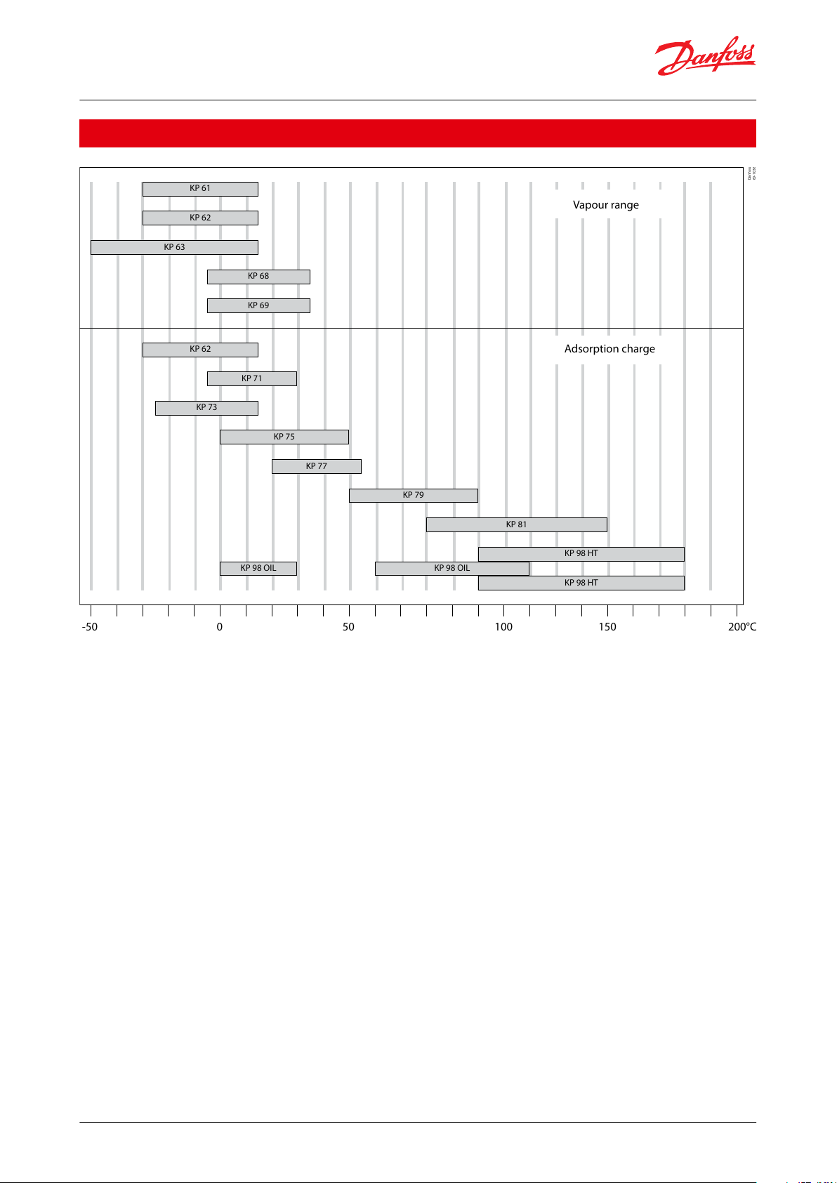
KP 63
KP 68
KP 69
KP 62
KP 71
KP 73
KP 75
KP 77
KP 79
KP 81
KP 98 HT
KP 98 HT
KP 98 OILKP 98 OIL
Vapour range
Adsorption charge
KP 61
KP 62
-50 50 100 150 200°C0
Danfoss
60-1038
Thermostat, Type KP
Portfolio overview
© Danfoss | Climate Solutions | 2021.03 AI203586420959en-000801 | 2
Page 3
Features
Description
Ambient temperature
-40 – 65 °C (80 °C for max. 2 hours)
Switch
Single-pole, double-throw (SPDT) changeover switch
Contact load
Alternating current
AC1 =16 A, 400 V
AC3 = 16 A, 400 V
Direct current
DC13: 12 W, 220 V control current
Wire dimensions
solid / stranded
0.75 – 2.5 mm
2
exible, without ferrules
0.7 – 2.5 mm
2
exible, with ferrules
0.5 – 1.5 mm
2
Tightening torque
max. 2 Nm
Rated impulse voltage
4 kV
Pollution degree
3
Short circuit protection, fuse
16 A
Insulation
400 V
Enclosure
IP30 / IP44
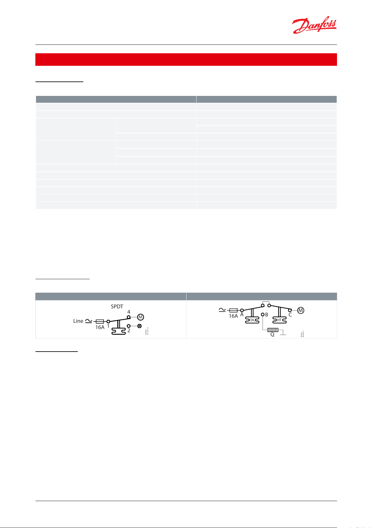
KP temperature control
KP 98
Line
SPDT
16A
1
2
4
M
Danfoss
60-894.12
M
HTOIL
16A
A
Q
B C
Thermostat, Type KP
Product specication
Technical data
Table 1: Technical data
Cable connection
Cable entry for cables 6 – 14 mm dia. A Pg 13.5 screwed cable entry can be used for 6 – 14 mm dia. cables. With 8 –
16 mm cables a standard Pg 16 screwed cable entry can be used.
Enclosure IP30 to EN 60529 / IEC 529
This grade of enclosure is obtained when the unit is mounted on a at surface or bracket. The bracket must be xed
so that all unused holes are covered.
Contact systems
Table 2: Contact systems
Terminology
Dierential
The dierential is the dierence between the make and break temperatures. A dierential is necessary for
satisfactory automatic operation of the plant.
Mechanical dierential (intrinsic dierential)
The mechanical dierential is the dierential set by the dierential spindle.
Operating dierential (thermal dierential)
The operating dierential is the dierential the plant operates on. Operating dierential is the sum of the
mechanical dierential and the dierential produced by the time constant.
Reset
1. Manual reset:
Units with manual reset can only be restarted after the reset button has been activated. On min. reset units the set
value is equal to the cut-out value for falling temperature. On max. reset units the set value is equal to the cut-out
value for rising temperature.
© Danfoss | Climate Solutions | 2021.03 AI203586420959en-000801 | 3
Page 4
1
2
3
7
8
9
15
17
12
16
4
1
2
Danfoss
60-296.16
Danfoss
60-1032.10
15
12162813
7
9
13
14
Thermostat, Type KP
2. Automatic reset:
These units are automatically reset after operational stop.
Setting
Thermostats with automatic reset
Set the upper activating temperature on the range scale.
Set the dierential on the "DIFF" scale. The temperature setting on the range scale will then correspond to the
temperature at which the refrigeration compressor will be started on rising temperature. The compressor will be
stopped when the temperature has fallen in relation to the dierential setting.
Note that the dierential depends on the range setting. Therefore, the dierential scale must only be used as
guideline.
If with low stop temperature settings the compressor will not stop, check whether the dierential is set at too high a
value!
Thermostats with minimum reset
Set the stop temperature on the range scale. The dierential is a xed setting.
The compressor can be restarted by pressing the “Reset button” after the temperature on the thermostat sensor has
risen by a value equal to the xed dierential setting.
Thermostats with maximum reset
Set the stop temperature on the range scale. The dierential is a xed setting.
The compressor can be restarted by pressing the “Reset button” after the temperature on the thermostat sensor has
fallen to a value equal to the xed dierential setting.
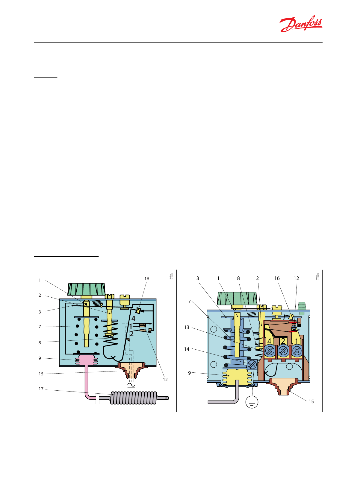
Design and function
Figure 1: Key sketch of KP thermostat
Figure 2: KP thermostat
© Danfoss | Climate Solutions | 2021.03 AI203586420959en-000801 | 4
Page 5

Danfoss
60-904.12
17
Danfoss
60-272.12
17
Danfoss
60-1037
17
Danfoss
60-1033.10
17
Danfoss
60-370.16
OIL
17 17
Max. reset
18512161183
7
10
15 13 11
9
14
Danfoss
60-421.13
KP 98
123789121314151617Temperature setting spindle
Dierential setting spindle
Main arm
Main spring
Dierential spring
Bellows
Switch
Terminals
Earth terminal
Cable entry
Tumbler
Sensor
Thermostat, Type KP
Figure 3: Adsorption charge
Figure 4: Vapour charge
Figure 5: Adsorption charge
Figure 6: Vapour charge
The switch in the KP has a snap-action function and the bellows move only when the cut-in or cut-out value is
reached.
The design of the KP thermostats aords the following advantages:
• High contact load
• Ultra-short bounce time
• Vibration resistance up to 4 g
• In the range 0 – 1000 Hz
• Long mechanical and electrical life
Figure 7: KP thermostat, dual type
Figure 8: KP 98
© Danfoss | Climate Solutions | 2021.03 AI203586420959en-000801 | 5
Page 6

19
17
9
Danfoss
60-910.10.20
91719
Bellows element
Sensor (bulb)
Capillary tube
13579101112131415161718Temperature setting spindle, OIL
Main arm
Temperature setting spindle, HT
Main spring
Bellows
Capillary tube, OIL
Capillary tube, HT
Switch
Terminals
Earth terminal
Cable entry
Tumbler
Sensor (bulb)
Locking plate
Thermostat, Type KP
Dual thermostat KP 98 is used to provide protection against excessively high discharge gas temperature and to
ensure a suitable oil temperature in the compressor.
To avoid the temperature of the hot gas exceeding the maximum permissible value during extreme operating
conditions (low evaporating pressure, high condensing pressure, high suction vapour superheat) a KP 98
thermostat can be used on the high temperature side (HT). If the temperature of the hot gas becomes too high the
refrigerant will break down and the compressor discharge valve will become damaged.
The risk is greatest in refrigeration systems that operate on a high compression ratio (e.g. in systems with NH3 or
R22) and in applications with hot gas bypass.
This unit has two separate thermostat functions. The HT sensor that controls the discharge gas temperature is tted
on the discharge tube immediately after the compressor.
For larger compressors, the sensor can be built into the discharge line.
The OIL sensor that controls the oil temperature is located in the compressor oil sump.
Charges
1. Vapour charge
Figure 9: Vapour charge
Here the interdependence between the pressure and temperature of saturated vapour is utilized, i.e. the element is
charged with saturated vapour plus a small amount of liquid.
The charge is pressure-limited; a further increase in pressure after evaporation of all the liquid in the sensor (17) will
only result in a small pressure increase in the element.
This principle can be utilized in thermostats for low temperature, etc. where evaporation must be able to take place
from the free liquid surface in the sensor (within the operating range of the thermostat), and where at the same
time, the bellows must be protected against deformation when kept at normal ambient temperatures. Since the
pressure in the element depends on the temperature at the free liquid surface, the thermostat must always be
placed so that the sensor is colder than the rest of the thermostatic element.
The evaporated liquid will recondense at the coldest point, i.e. the sensor. Thus, as intended, the sensor becomes
the temperature-controlling part of the system.
NOTE:
When the sensor is coldest, the ambient temperature has no eect on regulating accuracy.
© Danfoss | Climate Solutions | 2021.03 AI203586420959en-000801 | 6
Page 7

19
17
9
Danfoss
60-909.10.20
91719
Bellows element
Sensor (bulb)
Capillary tube
Danfoss
60-298.15.10
44
84
14
61
M4 (8 - 32 UNC)
18
18
25.4
13
23
32
8
64
Ø5
Ø5
44
122
61
27
51
14.5
35
49
25.4
M4(8 - 32 UNC)
18
25.4
Ø5
Thermostat, Type KP
2. Adsorption charge
Figure 10: Adsorption charge
In this case the charge consists partly of a superheated gas and partly of a solid having a large adsorption surface.
The solid is concentrated in the sensor (17) and it is therefore always the sensor that is the temperature-controlling
part of the thermostatic element.
The sensor can be placed warmer or colder than thermostat housing and capillary tube, but variations from 20 °C
ambient temperature will inuence the scale accuracy.
Dimensions [mm] and weights [kg]
Figure 11: KP 61 – 81
Figure 13: KP 98
Figure 12: Mounting holes (back of KP)
Figure 14: Mounting holes (back of KP)
© Danfoss | Climate Solutions | 2021.03 AI203586420959en-000801 | 7
Page 8

11
16
6.2
40
5.5
25.4
ø3.45
ø5
79.5
91.5
4
11
25.4
28.6
ø5
25.4
71.1
15
15
12
12
39
24.5
16.5
12.5
Danfoss
60-299.12.12
A
KP 61, KP 63,
KP 69
B
KP 61, KP 63
C1
KP 62, KP 68,
C2
KP 62
9.5
70
30
40 25
78
Danfoss
60-300.15.11
16
170
D2
KP 73
E2
KP 71
E3
KP 77, KP 73,
KP 75, KP 77,
KP 98
D1
KP 73,
KP 79,
KP 81
E1
KP 73
F
KP 75
9.5
9.5
10
115
85 85
95
125
25
ø5
50
40
6.4
Thermostat, Type KP
Figure 15: Wall bracket
Figure 17: Thermostat sensor types A, B and C
Figure 16: Angle bracket
Figure 18: Thermostat sensor types D, E and F
Net weight
• KP 61 - 81: approx. 0.4 kg
• KP 98: approx. 0.6 kg
© Danfoss | Climate Solutions | 2021.03 AI203586420959en-000801 | 8
Page 9

Charge
Type
Bulb type
Regulating
range
Dierential ∆t
Reset
Max. bulb
temp.
Capillary tube
length
Code no.
Lowest tem‐
perature
Highest tem‐
perature
[°C]
[°C]
[°C]
[°C]
[m]
Vapour
(1)
KP 61A-30 – 15
5.5 – 23
1.5 – 7
aut.
1202060L110066
KP 61A-30 – 15
5.5 – 23
1.5 – 7
aut.
1205060L110166
KP 61B-30 – 13
4.5 – 23
1.2 – 7
aut.
1202060L110266
KP 61B-30 – 15
5.5 – 23
1.5 – 7
aut.
120
2
060L110366
(3)
KP 61B-30 – 15
5.5 – 23
1.5 – 7
aut.
120
2
060L112866
(3) (4)
KP 61A-30 – 15
Fixed 6
Fixed 2
min.
1205060L110466
KP 61B-30 – 15
Fixed 6
Fixed 2
min.
1202060L110566
KP 62
C 1
-30 – 15
6.0 – 23
1.5 – 7
aut.
120–060L110666
KP 63A-50 – 10
10.0 – 70
2.7 – 8
aut.
1202060L110766
KP 63B-50 – 10
10.0 – 70
2.7 – 8
aut.
1202060L110866
KP 68
C 1
-5 – 35
4.5 – 25
1.8 – 7
aut.
120–060L111166
KP 69B-5 – 35
4.5 – 25
1.8 – 7
aut.
1202060L111266
Adsorbtion
(2)
KP 62
C 2
-30 – 15
5.0 – 20
2.0 – 8
aut.
80
–
060L111066
(3) (4)
KP 71
E 2
-5 – 20
3.0 – 10
2.2 –9
aut.
802060L111366
KP 71
E 2
-5 – 20
Fixed 3
Fixed 3
min.
802060L111566
KP 73
E 1
-25 – 15
12.0 – 70
8.0 – 25
aut.
802060L111766
KP 73
D 1
-25 – 15
4.0 – 10
3.5 – 9
aut.
802060L111866
(3)
KP 73
D 1
-25 – 15
Fixed 3.5
Fixed 3.5
min.
802060L113866
KP 73
D 2
-20 – 15
4.0 – 15
2.0 – 13
aut.
553060L114066
KP 73
D 1
-25 – 15
3.5 – 20
3.25 – 18
aut.
802060L114366
KP 75F0 – 35
3.5 – 16
2.5 – 12
aut.
1102060L112066
KP 75
E 2
0 – 35
3.5 – 16
2.5 – 12
aut.
1102060L113766
KP 77
E 3
20 – 60
3.5 – 10
3.5 – 10
aut.
1302060L112166
KP 77
E 3
20 – 60
3.5 – 10
3.5 – 10
aut.
1303060L112266
KP 77
E 2
20 – 60
3.5 – 10
3.5 – 10
aut.
1305060L116866
KP 79
E 3
50 – 100
5.0 – 15
5.0 – 15
aut.
1502060L112666
KP 81
E 3
80 – 150
7.0 – 20
7.0 – 20
aut.
2002060L112566
KP 81
E 3
80 – 150
Fixed 8
Fixed 8
max.
2002060L115566
KP 98
E 2
OIL: 60 – 120
OIL: Fixed 14
OIL: Fixed 14
max.
150
1
060L113166
E 2
HT: 100 – 180
HT: Fixed 25
HT: Fixed 25
max.
250
2
Thermostat, Type KP
Ordering
Table 3: Standard thermostat type KP
(1)
(1)
Bulb must always be placed colder than the thermostat housing and capillary tube. The thermostat will then regulate independent of ambient
Bulb must always be placed colder than the thermostat housing and capillary tube. The thermostat will then regulate independent of ambient
temperature.
temperature.
(2)
(2)
Bulb can be placed warmer or colder than thermostat housing and capillary tube, but variations from 20 °C ambient temperature will inuence
Bulb can be placed warmer or colder than thermostat housing and capillary tube, but variations from 20 °C ambient temperature will inuence
the scale accuracy.
the scale accuracy.
(3)
(3)
With manual switch, not isolating switch.
With manual switch, not isolating switch.
(4)
(4)
Panel mounting model with top plate.
Panel mounting model with top plate.
© Danfoss | Climate Solutions | 2021.03 AI203586420959en-000801 | 9
Page 10

Thermostat bulb types
Description
A
Danfoss
60L8012
Straight capillary tube
B
Danfoss
60L8032
ø9.5 × 70 mm remote air coil
C
Danfoss
60L8013
C1: ø40 × 30 mm air coil
C2: ø25 × 67 mm air coil
(integral with thermostat)
D
Danfoss
60L8012
D1: ø10 × 85 mm double contact remote bulb
D2: ø16 × 170 mm double contact remote bulb
NOTE:
Cannot be used in sensor (bulb) pocket
E
Danfoss
60L8008
E1: ø6.4 × 95 mm remote bulb
E2: ø9.5 × 115 mm remote bulb
E3: ø9.5 × 85 mm remote bulb
F
Danfoss
60L8018
ø25 × 125 mm remote duct coil
Thermostat, Type KP
Table 4: Thermostat bulb types
© Danfoss | Climate Solutions | 2021.03 AI203586420959en-000801 | 10
Page 11

Document name
Document type
Document topic
Approval authority
060-9638.AA
Manufacturers Declaration
China RoHS
Danfoss
060-9650.AD
EU Declaration
LVD/RoHS
Danfoss
BV 02281-J0 BV
Marine - Safety Certicate
BV
BV SMS.W.II-2179-B.0
Marine - Manufacturing Permission
BV
CCC 2003010305069849
Electrical - Safety Certicate
CCC
DNV GL TAA000026F
Marine - Safety Certicate
DNV GL
LR 17-20046
Marine - Safety Certicate
LR
RINA ELE-086320XG-001
Marine - Safety Certicate
RINA
UL E31024
Electrical - Safety Certicate
UL
Thermostat, Type KP
Certicates, declarations, and approvals
The list contains all certicates, declarations, and approvals for this product type. Individual code number may have
some or all of these approvals, and certain local approvals may not appear on the list.
Some approvals may change over time. You can check the most current status at danfoss.com or contact your local
Danfoss representative if you have any questions.
Table 5: Certicates, declarations, and approvals
© Danfoss | Climate Solutions | 2021.03 AI203586420959en-000801 | 11
Page 12

Online support
Danfoss oers a wide range of support along with our products, including digital product information, software,
mobile apps, and expert guidance. See the possibilities below.
The Danfoss Product Store
The Danfoss Product Store is your one-stop shop for everything product related—no matter where
you are in the world or what area of the cooling industry you work in. Get quick access to essential
information like product specs, code numbers, technical documentation, certications, accessories,
and more.
Start browsing at store.danfoss.com.
Find technical documentation
Find the technical documentation you need to get your project up and running. Get direct access to
our ocial collection of data sheets, certicates and declarations, manuals and guides, 3D models
and drawings, case stories, brochures, and much more.
Start searching now at www.danfoss.com/en/service-and-support/documentation.
Danfoss Learning
Danfoss Learning is a free online learning platform. It features courses and materials specically
designed to help engineers, installers, service technicians, and wholesalers better understand the
products, applications, industry topics, and trends that will help you do your job better.
Create your Danfoss Learning account for free at www.danfoss.com/en/service-and-support/learning.
Get local information and support
Local Danfoss websites are the main sources for help and information about our company and
products. Find product availability, get the latest regional news, or connect with a nearby expert—all
in your own language.
Find your local Danfoss website here: www.danfoss.com/en/choose-region.
Coolselector®2 - nd the best components for you HVAC/R system
Coolselector®2 makes it easy for engineers, consultants, and designers to nd and order the best
components for refrigeration and air conditioning systems. Run calculations based on your operating
conditions and then choose the best setup for your system design.
Download Coolselector®2 for free at coolselector.danfoss.com.
Danfoss can accept no responsibility for possible errors in catalogues, brochures and other printed material. Danfoss reserves the right to alter its
products without notice. This also applies to products already on order provided that such alterations can be made without subsequential
changes being necessary in specications already agreed. All trademarks in this material are property of the respective companies. Danfoss and
the Danfoss logotype are trademarks of Danfoss A/S. All rights reserved.
© Danfoss | Climate Solutions | 2021.03 AI203586420959en-000801 | 12
 Loading...