

Danfoss
60-1416.10
Danfoss
60-1416.10
Danfoss
60-1416.10
Installation guide
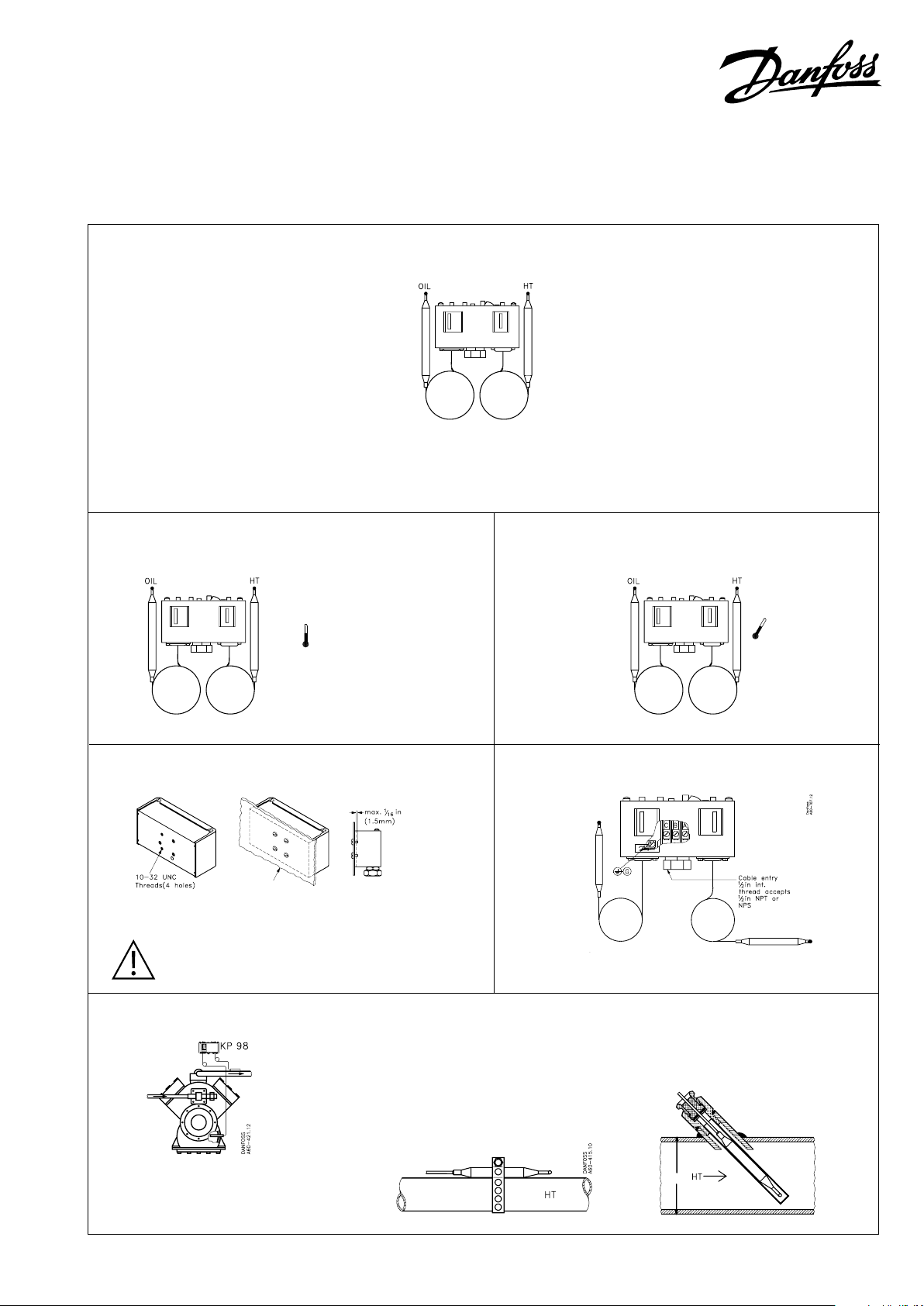
Thermostat
Type KP 98 (cross ambient)
060R9749
Oil temp. High temp.
(OIL) bulb (HT) bulb
KP 98 man. (OIL)/man.(HT) rese t
Note:
Code no. stamped on top of control.
Ambient temperatures Max. bulb temperatures
min. -40 °F (-40 °C)
max. 150 °F ( 65 °C)
(175 °F (80 °C) for max. 2 hours)
max. 300 °F (150 °C)
060R9749
max. 480 °F (250 °C)
Enclosure Cable entry
~ NEMA 1
Danfoss
60-786.12
CAUTION:
The mounting panel must be plane to avoid
damage of control.
Mounting
Mount OIL temperature bulb in compressor
crankcase and the HT bulb on/in discharge line
as shown.
Small pipe size Large pipe size
OD > 3.5 in.
Danfoss
60-1419.10
O.D.
© Danfoss A/S (RC-MDP / jmn), 2014-08 DKRCC.PI.CA0.A6.22 / 520H8513 1
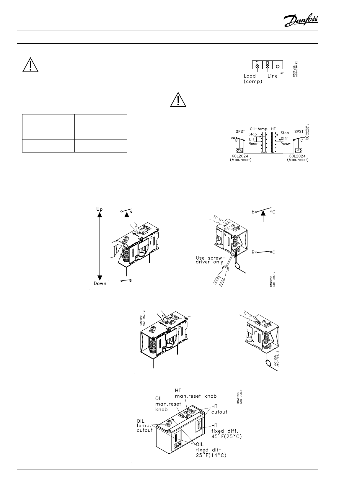
Wiring
CAUTION: disconnect power supply
before wiring connections are made
to avoid possible electrical shock or
damage to equipment.
All wiring should conform to the National
Electrical Code and local regulations.
Contact load ratings
120 V a.c. 16 FLA, 96 LRA
240 V a.c. 8 FLA, 48 LRA
240 V d.c. 12 W pilot duty
See label inside cover.
Manual tripping
(Electrical contacts/wiring test)
OIL side HT side
B
SPST
Terminal block
CAUTION: Use terminal screws furnished in the
contact block. Use tightening torque 20 lb. in. (2.3 Nm).
Use copper wire only.
B-C open on oil temperature rise
B-C open on discharge
temperature rise
A is not used
See label for current
wiring inside cover.
C
Contact positionContact position
TRIP
use FINGERS ONLY!
(Do NOT use screwdriver)
Manual reset
To resume control operation after safety
cut-out, push man. reset knob as indicated
Note:
OIL/HT man. reset is possible only after oil
or discharge temperature is equal to or has
dropped below cut-in value.
Adjustment spindle(s) location
Contact position
Danfoss
60-801.13
Contact position
C
B
OIL
reset
HT
man. reset
KP 98 A. MAN./MAN. RESET
2 DKRCC.PI.CA0.A6.22 / 520H8513 © Danfoss A/S (RC-MDP / jmn), 2014-08

Danfoss
60-1417.10
Danfoss
60-1418.10
Setting
Oil temp. (OIL) side setting High temp. (HT) side setting
1. Adjust range spindle to
desired CUT-OUT value
(max. allowable
oil temp.)
2. Dierential (DIFF.)
is xed 25 °F (14 °C)
Value printed on
scale plate
CUT OUT minus DIFFERENTIAL equals CUT OUT minus DIFFERENTIAL equals
CUT-IN CUT-IN
Example: Example:
CUT-OUT – DIFF. = CUT-IN CUT-OUT - DIFF. = CUT-IN
200 °F – 25 °F = 175 °F 325 °F - 45 °F = 280 °F
(93 °C) (14 °C) (79 °C) (163 °C) (25 °C) (138 °C)
OIL temp.
scale
Cut out
Di.
1. Adjust range spindle to
desired CUT-OUT value
(max. allowable
discharge temp.)
2. Dierential (DIFF.)
is xed 45 °F (25 °C)
Value printed on
scale plate
HT
scale
Cut out
Di.
Note:
CUT-OUT = compressor cut-out
CUT-IN = compressor cut-in
Adjustment
Danfoss
60-802.12
Note:
Remove lockplate before adjustment.
Replace lockplate after adjustment (if desired).
3 DKRCC.PI.CA0.A6.22 / 520H8513 © Danfoss A/S (RC-MDP / jmn), 2014-08
 Loading...