

Page 1
www.danfoss.com/ir
Application Handbook
Industrial Refrigeration
Ammonia and CO2 Applications
© Danfoss A/S (RC-MDP/MWA), 2020-10 AB13778641621700-000702 1
Page 2

Application Handbook Industrial Refrigeration ammonia and CO2 applications
2 AB13778641621700-000702 © Danfoss A/S (RC-MDP/MWA), 2020-10
Page 3

Application Handbook Industrial Refrigeration ammonia and CO2 applications
Content Page
Introduction ................................................................................................................................................................................... 3
1.1 Refrigerants ............................................................................................................................................................................. 4
1.2 Refrigerant feed to the evaporator ............................................................................................................................................ 6
1.3 One-stage systems ................................................................................................................................................................... 8
1.4 Two-stage/multistage systems .................................................................................................................................................. 9
1.5 Cascade systems .................................................................................................................................................................... 12
1.6 Transcritical systems .............................................................................................................................................................. 13
Compressor controls ..................................................................................................................................................................... 18
2.1 Reverse flow control ............................................................................................................................................................... 19
2.2 Suction pressure control ......................................................................................................................................................... 20
2.3 Compressor capacity control ................................................................................................................................................... 21
2.4 Discharge Temperature Control with Liquid Injection ................................................................................................................ 24
2.5 Economizer damper ................................................................................................................................................................ 26
2.6 Summary ............................................................................................................................................................................... 27
Condenser controls ....................................................................................................................................................................... 28
3.1 High-pressure float valve operation ......................................................................................................................................... 28
3.2 Low-pressure float valve operation .......................................................................................................................................... 29
3.3 Air-cooled condensers............................................................................................................................................................. 29
3.4 Evaporative condensers .......................................................................................................................................................... 33
3.5 Water-cooled condensers ........................................................................................................................................................ 36
3.6 Summary ............................................................................................................................................................................... 38
Liquid level regulation ................................................................................................................................................................... 39
4.1 High-pressure liquid level regulation system (HP LLRS) ............................................................................................................. 41
4.2 Low-pressure liquid level regulation system (LP LLRS) .............................................................................................................. 47
4.3 Summary ............................................................................................................................................................................... 52
Evaporator controls ...................................................................................................................................................................... 53
5.1 Temperature controls ............................................................................................................................................................. 54
5.2 Liquid supply control............................................................................................................................................................... 58
5.3 Injection with a solenoid valve (EVRA) ..................................................................................................................................... 65
5.4 Injection with a pulse width modulation AKV(A) valve............................................................................................................... 65
5.5 Risers .................................................................................................................................................................................... 68
5.6 Defrost methods .................................................................................................................................................................... 73
5.7 Summary ............................................................................................................................................................................... 90
Oil systems .................................................................................................................................................................................. 92
6.1 Oil cooling controls ................................................................................................................................................................. 93
6.2 Oil differential pressure controls .............................................................................................................................................. 98
6.3 Oil recovery system .............................................................................................................................................................. 102
6.4 Summary ............................................................................................................................................................................. 106
Safety systems ........................................................................................................................................................................... 107
7.1 Pressure relief devices .......................................................................................................................................................... 107
7.2 Pressure and temperature limiting devices ............................................................................................................................. 110
7.3 Liquid level safety devices ..................................................................................................................................................... 111
7.4 Refrigerant detection ............................................................................................................................................................ 112
Refrigerant pump controls........................................................................................................................................................... 116
8.1 Pump protection with differential pressure control .................................................................................................................. 117
8.2 Pump bypass flow control ..................................................................................................................................................... 120
8.3 Pump pressure control .......................................................................................................................................................... 122
8.4 Summary ............................................................................................................................................................................. 123
Others ....................................................................................................................................................................................... 124
9.1 Filter driers in fluorinated systems ......................................................................................................................................... 124
9.2 Water removal for CO2 systems ............................................................................................................................................ 126
9.3 Water removal for ammonia systems ..................................................................................................................................... 128
9.4 Air purging systems .............................................................................................................................................................. 130
9.5 Heat recovery systems.......................................................................................................................................................... 135
Using CO2 in refrigeration systems ............................................................................................................................................ 136
10.1 CO2 as a refrigerant ........................................................................................................................................................... 137
10.2 Comparision of line sizings in CO2 systems ........................................................................................................................... 138
10.3 -Subcritical CO2 systems ..................................................................................................................................................... 145
10.4 Special considerations for CO2 refrigeration systems ............................................................................................................. 153
10.5 Conclusion ......................................................................................................................................................................... 157
10.6 Safety and gas detection ..................................................................................................................................................... 159
10.7 Gas detection ..................................................................................................................................................................... 159
10.8 Pressure control CO2 systems ............................................................................................................................................. 161
10.9 Cascade system controls ..................................................................................................................................................... 163
10.10 Control methods for hot gas defrosting .............................................................................................................................. 164
10.11 Oil in CO2 systems ............................................................................................................................................................ 171
10.12 Water in CO2 Systems ....................................................................................................................................................... 174
Transcritical CO2 systems ......................................................................................................................................................... 179
11.1 Explanation of the transcritical cycle. ................................................................................................................................... 179
11.2 Typical CO2 transcritical system types .................................................................................................................................. 184
11.3 CO2 in Industrial refrigeration ............................................................................................................................................. 190
11.4 Industrial CO2 transcritical systems. .................................................................................................................................... 193
11.5 Defrosting of industrial pump-circulated transcritical systems ................................................................................................ 209
11.6 Oil management ................................................................................................................................................................. 211
11.7 Oil return ........................................................................................................................................................................... 212
11.8 Heat recovery ..................................................................................................................................................................... 217
11.9 Design pressure and safety ................................................................................................................................................. 223
Heat exchangers ...................................................................................................................................................................... 225
12.1 Heat transfer fundamentals ................................................................................................................................................. 230
12.2 Plate heat exchangers ......................................................................................................................................................... 237
12.3 Installation of heat exchangers ............................................................................................................................................ 242
© Danfoss A/S (RC-MDP/MWA), 2020-10 AB13778641621700-000702 1
Page 4

Application Handbook Industrial Refrigeration ammonia and CO2 applications
Foreword:
Some of the solutions presented here might be subject to special requirements in local laws and legislation and Danfoss has made no verification of such
and expressly disclaims any compliance there with. A
licensed and skilled professional engineer should always be consulted when designing, using, making or
selling any device or equipment to ensure compliance with applicable laws and standards.
Refrigeration systems and methods of operating the
same may be subject to intellectual property rights
in some jurisdictions. A licensed attorney should always be consulted when designing, using, making or
selling any such system, methods or equipment to
ensure freedom to operate.
Danfoss shall have no liability or obligation to indemnify or hold harmless for any claims, legal proceedings, losses, actions, damages, suits, judgments, liabilities, and expenses, including attorneys’ fees, arising from any information provided in this document,
or arising out of the modification or combination of
any Danfoss product or system with any third party
equipment, materials or intellectual property.
All diagrams and drawings are included as principle
sketches and for illustration purposes only. All
Danfoss products and pipe lines etc. should be dimensioned according to the actual capacity and temperature range they are to be used at.
Any information, including, but not limited to information on selection of product, its application or
use, product design, weight, dimensions, capacity or
any other technical data in this document shall be
considered informative, and is only binding if and to
the extent, explicit reference is made in a quotation
or order confirmation by Danfoss. Danfoss reserves
the right to alter its products without notice.
This document itself, all text, diagrams. drawings
and all trademarks in this material are property of
Danfoss A/S or Danfoss group companies. Danfoss
and the Danfoss logo are trademarks of Danfoss A/S.
All rights reserved.
2 AB13778641621700-000702 © Danfoss A/S (RC-MDP/MWA), 2020-10
www.danfoss.com\ir
Page 5

Application Handbook Industrial Refrigeration ammonia and CO2 applications
Introduction
The refrigeration systems and their applications described in this guide are all vapour compression refrigeration systems.
the refrigerant to condense and release heat. When
the refrigerant is fully condensed, it is expanded to
lower the pressure, the evaporation pressure, corresponding to a saturation temperature that is low
Vapour compression refrigeration systems utilise the
heat absorbed or released in a phase change, the latent heat, of refrigerants. The boiling temperature
enough for the refrigerant to absorb heat from the
cooled environment, thus evaporating, and the processes repeat themselves.
changes with the pressure of the refrigerant.
The refrigerant is pressurised at different pressure
levels, evaporation pressure levels and condensation
pressure levels, to absorb heat from the heat source
(cold room) and release heat to the heat sink (ambient), thus the refrigerant acts as a heat transport
media. The refrigerant is evaporated and absorbs
heat from the environment that is to be cooled.
Once the refrigerant is evaporated, it is compressed
to a higher pressure level, where the saturation tem-
To visualise the processes, a log(p)-h diagram is
shown in Figure 1.1. The log(p)-h diagram shows the
thermodynamic properties of a refrigerant. It is used
for representing refrigeration cycles by plotting in
state points from the refrigeration cycle. It can also
be used for reading values for the state points in a
refrigeration cycle. The log(p)-h diagram has been
created with the Danfoss calculation tool Coolselector2.
perature is higher than the ambient temperature for
Figure 1.1: Log(p)-h diagram for one-stage ammonia system
© Danfoss A/S (RC-MDP/MWA), 2020-10 AB13778641621700-000702 3
Page 6

Application Handbook Industrial Refrigeration ammonia and CO2 applications
A simple one-stage ammonia refrigeration cycle is
shown in the log(p)-h diagram above. In this example, the evaporation temperature is -10°C and the
condensation temperature is 35°C.
The bell shape seen in the diagram is the two-phase
area of the refrigeration and the horizontal lines inside the bell shape represent the evaporation ((4) to
1.1 Refrigerants
The refrigerant is the medium that transports energy
from the evaporator to the condenser. Different refrigerants have different thermodynamic properties,
such as latent heat, density, critical point etc. Different refrigerants also have different safety precautions, environmental impacts and regulations to be
taken into account when designing a refrigeration
system.
The most common refrigerants used in industrial systems are:
(1)) and the condensation ((2) to (3)). The area to the
left of the bell shape is the liquid phase, while the
area to the right of the bell shape is the vapour/gas
phase. In the gas phase, the pressure is increased
from (1) to (2) - this is the vapour compression. From
(3) to (4), the refrigerant liquid is expanded to the
evaporation pressure level.
Ammonia is toxic and flammable (in certain concentrations), so proper safety precautions must be
taken when handling large amounts of ammonia.
1.1.2 Carbon dioxide (CO
) – R744
2
CO2 is a non-toxic (in small concentrations), nonflammable substance that is present in the atmosphere. CO2 has become more popular in recent years
as CFC refrigerants have been phased out, especially
in smaller systems and as a secondary refrigerant in
commercial applications.
Ammonia – R717
Carbon dioxide (CO
Halocarbons – CFCs, HCFCs and HFCs
Hydrocarbons – HCs
) – R744
2
Safety systems, such as safety relief valves and gas
detectors are described in chapter 7.
1.1.1 Ammonia - R717
Ammonia is a natural refrigerant with the chemical
composition NH3. Ammonia is inexpensive, easy to
manufacture and has a high amount of latent heat,
which is why it is a very commonly used refrigerant
in industrial applications. At ambient conditions,
20°C and 1 atm, ammonia is lighter than air. Additionally, ammonia has no ozone depletion potential
(ODP) and no global warming potential (GWP).
Ammonia’s operational area as a refrigerant ranges
from around -40°C of evaporation temperature and
up. Ammonia is not compatible with copper, so steel
components should be used.
The challenges regarding CO2 are the high pressure
for condensation/recuperating and the low critical
temperature, requiring transcritical operation with
warm ambient temperatures. CO2 can be dangerous
when leaking, as it is not self-alarming like ammonia.
Large concentrations of CO2 can cause dizziness and,
in the most extreme cases, death. The other side of
CO2’s high pressure is that it is very efficient at low
temperatures, making it a good refrigerant for freezing applications. However, CO2’s triple point at -
56.6°C/5.1 bar abs is the lower limit for its use.
1.1.3 Halocarbons – CFCs, HCFCs and HFCs
Halocarbons are made by replacing one or more hydrogen atoms with halogens in methane and ethane
molecules.
Three classes of these exists: CFCs (chlorofluorocarbons), HCFCs (hydrochlorofluorocarbons) and HFCs
(hydrofluorocarbons). These refrigerant classes are
known for:
CFCs: All hydrogen atoms are substituted by either
chloride or fluoride, e.g. R11. These are very stable
4 AB13778641621700-000702 © Danfoss A/S (RC-MDP/MWA), 2020-10
Page 7

Application Handbook Industrial Refrigeration ammonia and CO2 applications
compounds with a long lifetime. CFCs are non-toxic
and non-flammable refrigerants. However, these refrigerants have been phased out because they contribute to the breakdown of the ozone layers in the
Earth’s stratosphere when they are leaked.
HCFCs: At least one hydrogen atom is present in
these molecules, e.g. R22, which is used to replace
R12. These components are less stable and have
shorter lifetimes, thus they are less harmful regarding ozone layer depletion and global warming potential. HCFCs are being phased out by some countries.
HFCs: These halocarbons do not contain either chlorine or bromine, e.g. R134a, and are therefore not
ozone depleting. However, they do still have a high
GWP and are therefore on a phasedown. The properties of R134a are close to R12, and therefore
R134a can normally replace R12 in new and existing
systems. Many new blends are entering the market
at the present time though. However, due to the relatively high GWP compared to natural refrigerants,
there is a risk that these will be phased out in the future.
1.1.4 Hydrocarbons – HCs
Hydrocarbons have become very common in domestic refrigeration applications. Hydrocarbons are flammable and explosive, but in small systems the charge
is typically too low to pose any risk, and these systems are typically hermetic. Isobutane - R600a is a
hydrocarbon refrigerant which is used in domestic
applications. R290 – propane – is used in some larger
chillers but is yet to be seen in large-scale industrial
applications.
© Danfoss A/S (RC-MDP/MWA), 2020-10 AB13778641621700-000702 5
Page 8
Application Handbook Industrial Refrigeration ammonia and CO2 applications
1.2 Refrigerant feed to the evaporator
There are two common ways that refrigerant is fed
to the evaporator in a vapour compression refrigeration system, which are presented in the following
paragraphs.
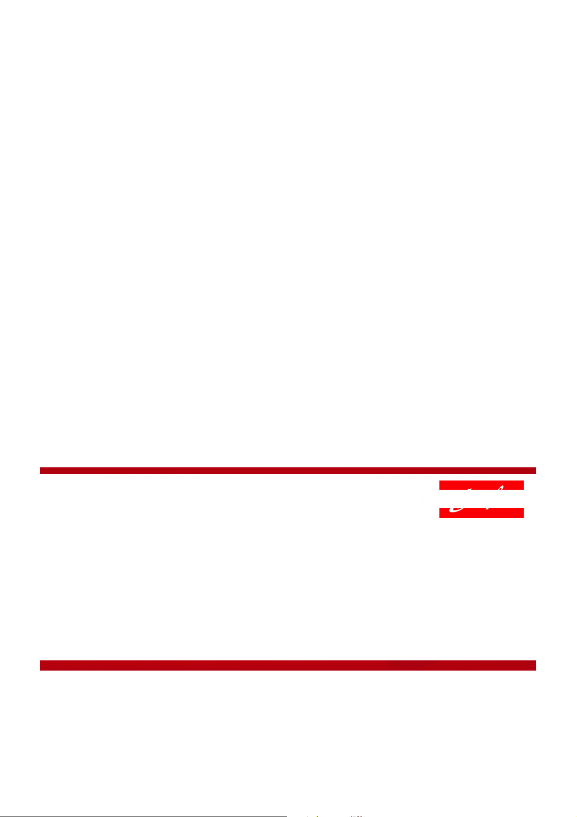
1.2.1 Direct expansion system (DX)
After expansion, the liquid/vapour mixture of refrigerant is fed directly to the evaporator. The refrigerant is then fully evaporated, so that only the vapour
phase is present at the evaporator outlet. To ensure
that no liquid is present in the suction line, the refrigerant vapour is superheated (the actual temperature is above saturation) in the evaporator before
A sketch of a direct expansion evaporator is shown
in Figure 1.2. The evaporator is depicted as a plate
heat exchanger, with the cooled product on the left
side and the refrigerant on the right side. The thermostatic expansion valve is regulated based on the
superheat measured on the suction line (line to compressor).
being fed to the compressor.
Figure 1.2: Direct expansion evaporator
An expansion valve is controlled by the superheat.
This is either done by a thermostatic expansion valve
DX Evaporator
or an electronic expansion valve.
To Compressor
By keeping a constant level of superheat at the evaporator outlet, the expansion valve feeds the right
flow of refrigerant to the evaporator according to
the cooling load.
A certain level of superheat should ensure that only
refrigerant vapour is fed to the compressor suction.
Liquid droplets in the suction will cause liquid hammering in the compressor.
TC
From Receiver
NOTE: A thermostatic expansion valve can only keep
a constant superheat, rather than a constant evapo-
rating temperature.
6 AB13778641621700-000702 © Danfoss A/S (RC-MDP/MWA), 2020-10
Page 9
Application Handbook Industrial Refrigeration ammonia and CO2 applications
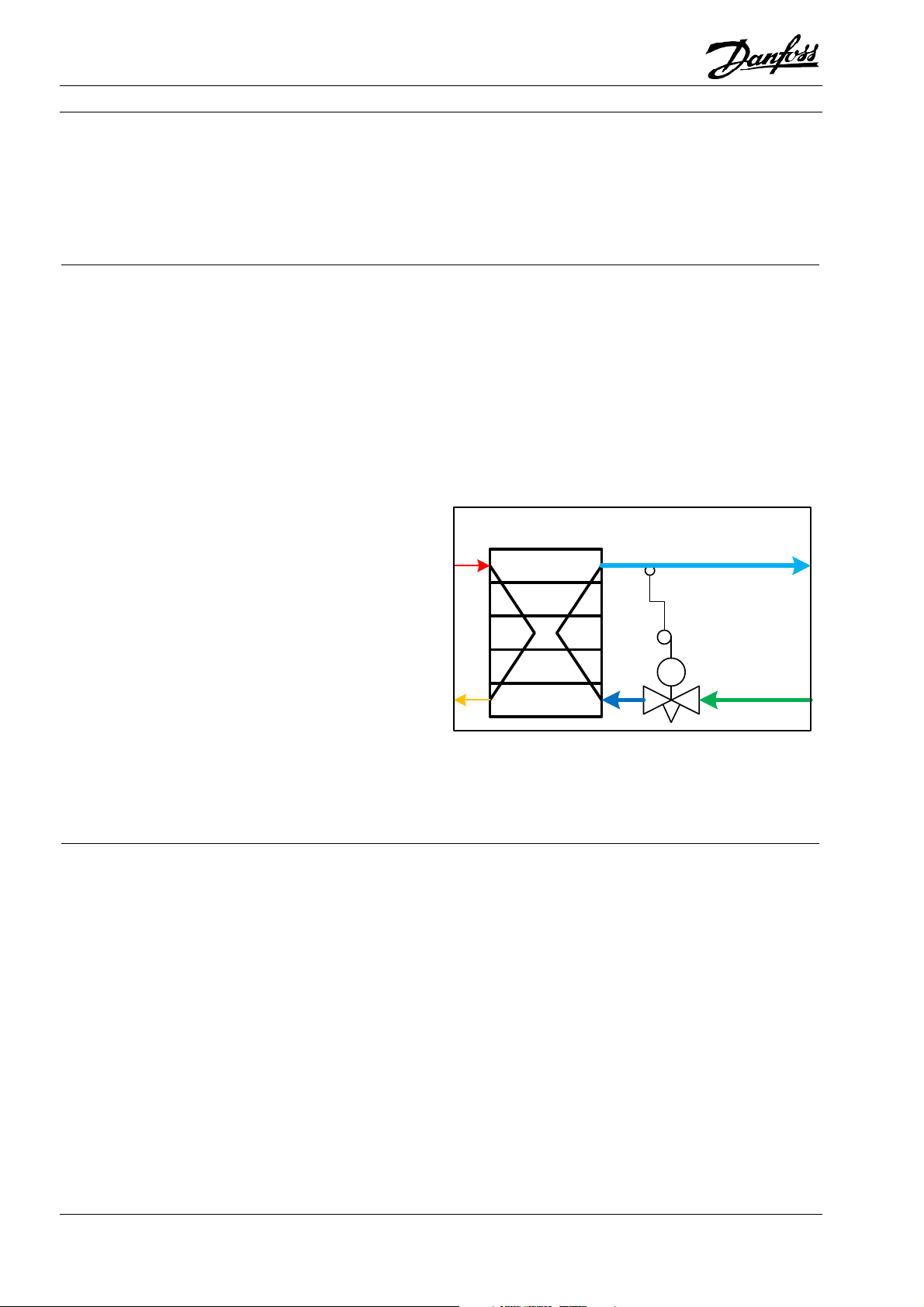
1.2.2 Circulated system (flooded system)
In circulated systems, the liquid/vapour mixture of
refrigerant is separated after the expansion in a sep-
A circulation system is therefore more efficient than
a corresponding DX system.
aration vessel. The saturated liquid phase of the refrigerant is pumped, or driven by gravity, into the
evaporator and is partially evaporated, so that a liquid/vapour mixture of the refrigerant is present at
the evaporator outlet. In the separator vessel, only
the saturated vapour will be fed to the compressor,
while the saturated liquid is circulated through the
A sketch of a flooded evaporator is shown in Figure
1.3. The evaporator type is the same as in Figure 1.2.
For the flooded evaporator, the pump is shown, but
it would be left out if it were a thermosyphon evapo-
rator driven by gravity.
Figure 1.3: Pumped flooded evaporator
evaporator.
As the evaporator does not need to superheat the
suction vapour, the entire surface is used for evaporation, making the flooded evaporator much more
efficient. Furthermore, creating superheat in a DX
Flooded
Evaporator
evaporator requires a higher temperature difference
and thus the evaporating temperature in a flooded
evaporator can be closer to the product temperature, allowing for a more efficient refrigeration system
To Compressor
From Receiver
© Danfoss A/S (RC-MDP/MWA), 2020-10 AB13778641621700-000702 7
Page 10
Application Handbook Industrial Refrigeration ammonia and CO2 applications
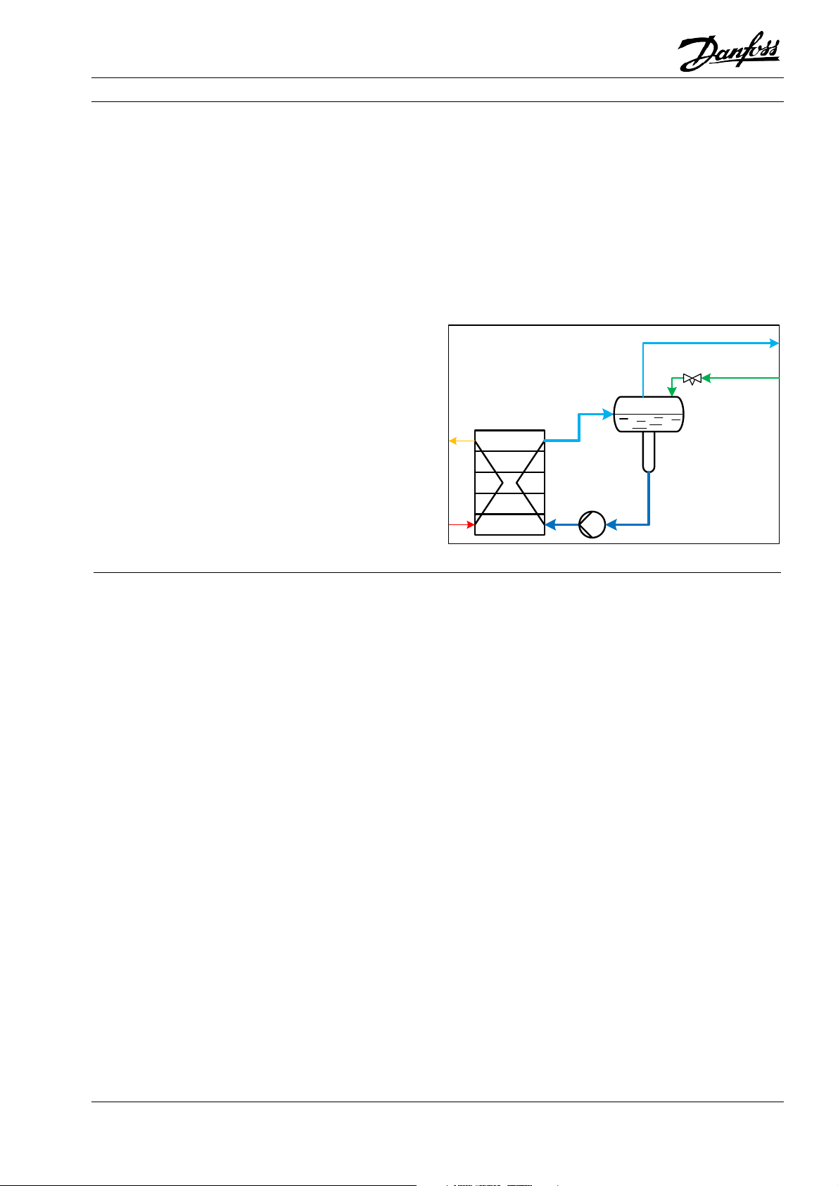
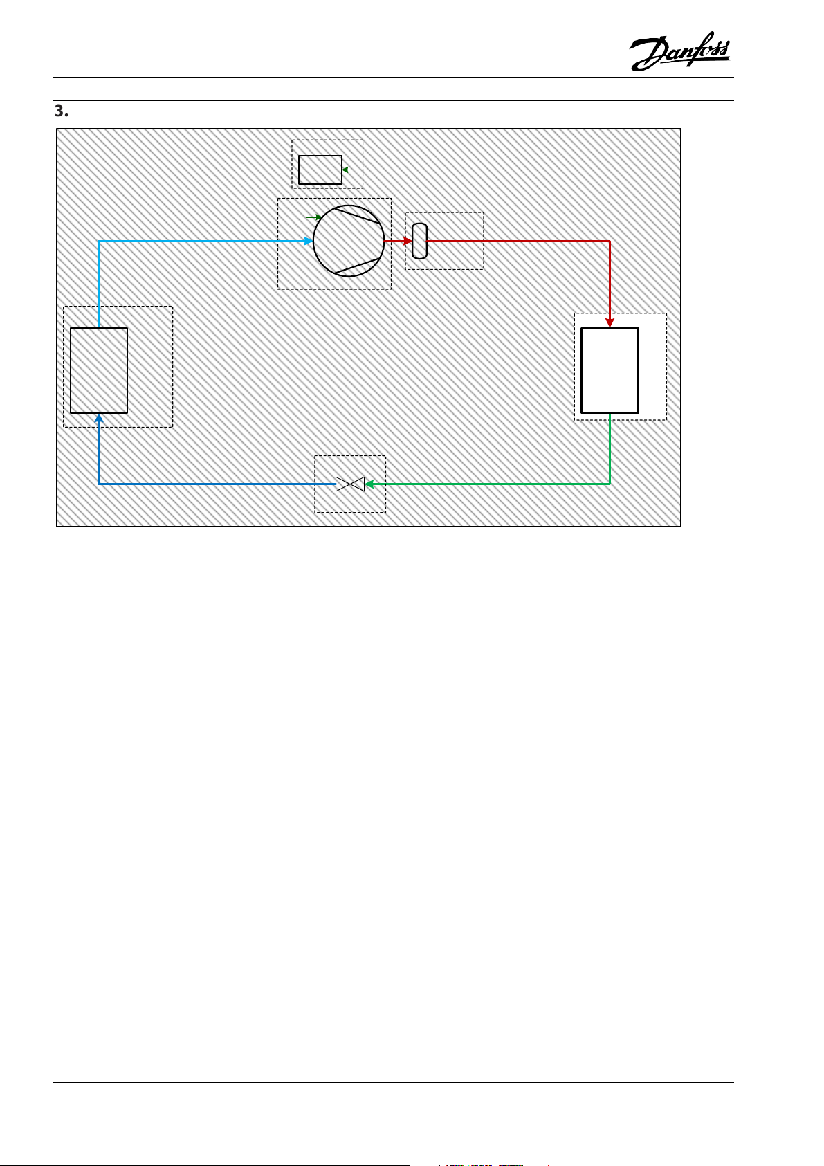
1.3 One-stage systems
One-stage or single-stage refrigeration systems are
refrigeration systems where the compression from
low pressure to high pressure is done in one stage. A
one-stage refrigeration system with the most basic
components is shown in
Figure 1.4.
Neither the evaporator nor the condenser is specified as a specific type, but rather represent the general concept of evaporation and condensation. Both
Figure 1.4: System diagram for a one-stage system
Oil Cooler
1 2
can be constructed and controlled in a number of
ways. A log(p)-h diagram for a one-stage system can
be seen in Figure 1.1. The numbers shown in
Figure 1.4 corresponds to the numbers shown for
the state points in the log(p)-h diagram.
Oil Separator
Compressor
Evaporator
4
Expansion valve
3
Condenser
8 AB13778641621700-000702 © Danfoss A/S (RC-MDP/MWA), 2020-10
Page 11
Application Handbook Industrial Refrigeration ammonia and CO2 applications
1.4 Two-stage/multistage systems
A two-stage or multistage refrigeration systems are
refrigeration systems with two or more stages of vapour compression.
Industrial two-stage refrigeration systems usually
have inter-stage cooling between compression
stages to cool the discharge gas from the first compression stage.
By cooling the discharge gas from the low-pressure
compressor, excessively high discharge temperatures from the high-pressure compressor are
avoided. The cooling in the inter-stage cooler is supplied by expanding some of the liquid refrigerant
from the condenser to the intermediate pressure,
where some of it evaporates in the process of cooling the LP compressor discharge gas. The gas mixed
from cooled LP compressor discharge gas, refrigerant flashed and refrigerant evaporated is passed to
the HP compressor.
Two or more stages of vapour compression are used
when there is a large difference between the evaporating and condensing temperature, which often results in compression ratios that are too high for the
compressors or results in other undesirable operat-
ing conditions. Additionally, the desire for another
temperature level or efficiency considerations may
result in a two-stage system being chosen over a sin-
gle stage.
It is therefore suitable to have two or more stages of
compression to have the compressors operating at
their optimal compression ratio, and within their op-
eration limits.
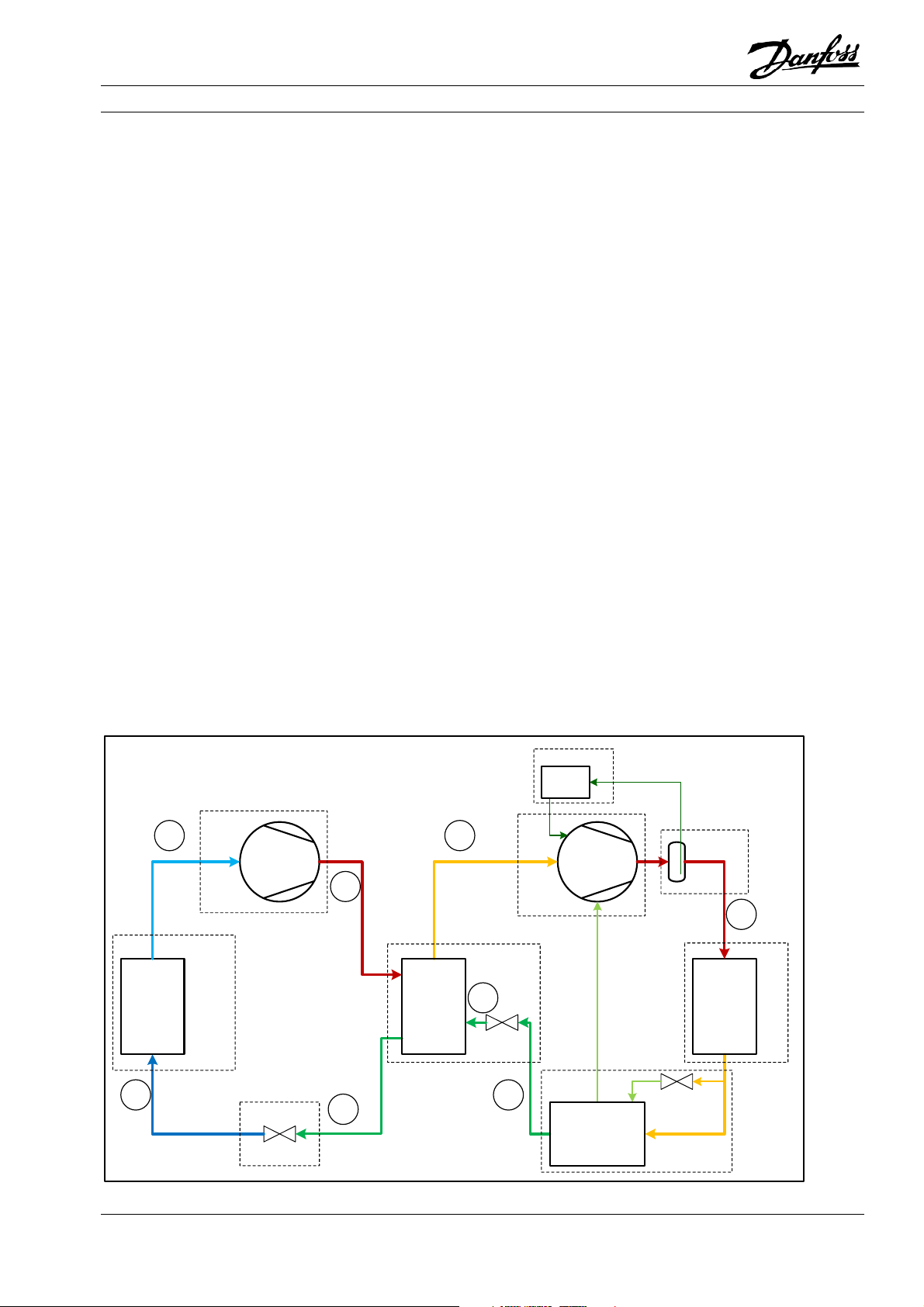
A system sketch of a two-stage refrigeration system
is shown in Figure 1.5. The figure is shown with an
inter-stage cooler and economiser. An economiser
like the one shown in the system diagram is used for
subcooling the refrigerant after the condenser by by-
passing and flashing some refrigerant. The bypassed
refrigerant is evaporated and fed to an economiser
port in the high-pressure compressor which can in-
crease the capacity and/or the efficiency of the sys-
tem. The LP compressor may also have an econo-
miser, but it is not shown here.
Figure 1.5: System diagram for two-stage system
LP Compressor
1
2
Evaporator
8
Expansion valve
7
3
HP Compressor
Inter-stage coole r
6
5
Oil Cooler
Oil Separator
4
Condenser
Economizer
© Danfoss A/S (RC-MDP/MWA), 2020-10 AB13778641621700-000702 9
Page 12
Application Handbook Industrial Refrigeration ammonia and CO2 applications
A log(p)-h diagram for the two-stage system is
shown in Figure 1.6. The numbering in Figure 1.5 follows the numbering of the state points shown in the
log(p)-h diagram. It should be noted that the evaporation temperature is -30°C and the condensation
temperature is kept at 35°C, as for the example for
the one-stage system. It should be noted how the in-
temperature from the high-pressure compression
stage. If no inter-stage cooling was used, the line (1)
to (2) would be extended and end on the same horizontal level as (4), but shifted to the right, thus increasing the discharge temperature to around
160°C, which is not acceptable (primarily for oil considerations).
ter-stage cooler helps to keep a low discharge gas
Figure 1.6: Log(p)-h diagram for two-stage ammonia system
(5)
(4)
(7)
(8)
(2)
(6)
(3)
(1)
10 AB13778641621700-000702 © Danfoss A/S (RC-MDP/MWA), 2020-10
Page 13

Application Handbook Industrial Refrigeration ammonia and CO2 applications
In the above Log(P)-H diagram, the economiser is
not shown. The economiser port is a port in screw
compressors that allows access to the compression
chamber after the suction port has closed. As such, if
a high enough pressure is applied to the economiser
port, an additional refrigerant flow can be added to
This is utilised with the economiser, which is a heat
exchanger that further cools the liquid from the con-
denser. To do this, a little of the condenser liquid
flow is flashed to a lower pressure/temperature,
where it is evaporated to cool the remaining liquid.
That modifies the Log(P)-H diagram a little:
the compressor without affecting the suction flow.
Figure 1.7: Log(p)-h diagram for two-stage ammonia system with economizer on the high stage
Low-stage compression from (1) to (2), de-superheating in the inter-stage cooler from (2) to (3) and
initial high-stage compression from (3) to (4) is the
same as in the non-economized system. The discharge from the high-stage compressor (6) is condensed from (6) to (7) as before. After the condenser
(7), a small amount of refrigerant is flashed to a
lower temperature (8), where it is evaporated and
added to the partially compressed suction gas of the
high-stage compressor. The resulting mixture is (5),
which is compressed together to the final discharge
the remaining liquid from (7) to (9). It is noteworthy
that the liquid flashed to the intermediate tempera-
ture is further to the left than it would have been
without the economizer, thus the enthalpy differ-
ence from (10) to (3) is bigger and that increases the
compressor’s cooling capacity. The power consump-
tion is increased as well, because there is an addi-
tional mass flow that needs to be compressed, but
the overall effect – depending on the operating con-
ditions – is a higher cooling capacity and, usually, a
higher COP.
at (6). The evaporative capacity is used to sub-cool
© Danfoss A/S (RC-MDP/MWA), 2020-10 AB13778641621700-000702 11
Page 14
Application Handbook Industrial Refrigeration ammonia and CO2 applications
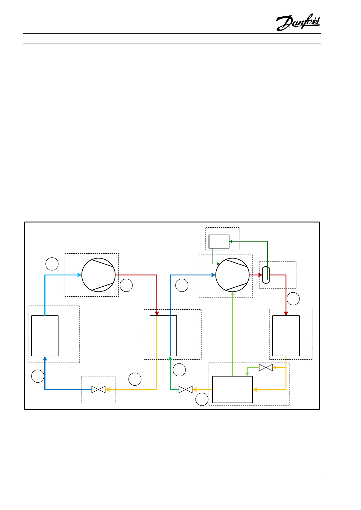
1.5 Cascade systems
A cascade system consists of two separate refrigeration circuits. The separate refrigeration circuits are
connected by a heat exchanger, which acts as a condenser for the low-temperature circuit and an evaporator for the high-temperature circuit.
The refrigerants for the two circuits can be different
and optimised for each circuit. For example, the refrigerant for the high-temperature circuit could be
ammonia, and the refrigerant for the low-temperature circuit could be CO2.
A CO2/ammonia system needs a smaller charge of
ammonia and proves to be more efficient in lowtemperature refrigeration than a similar two-stage
ammonia system.
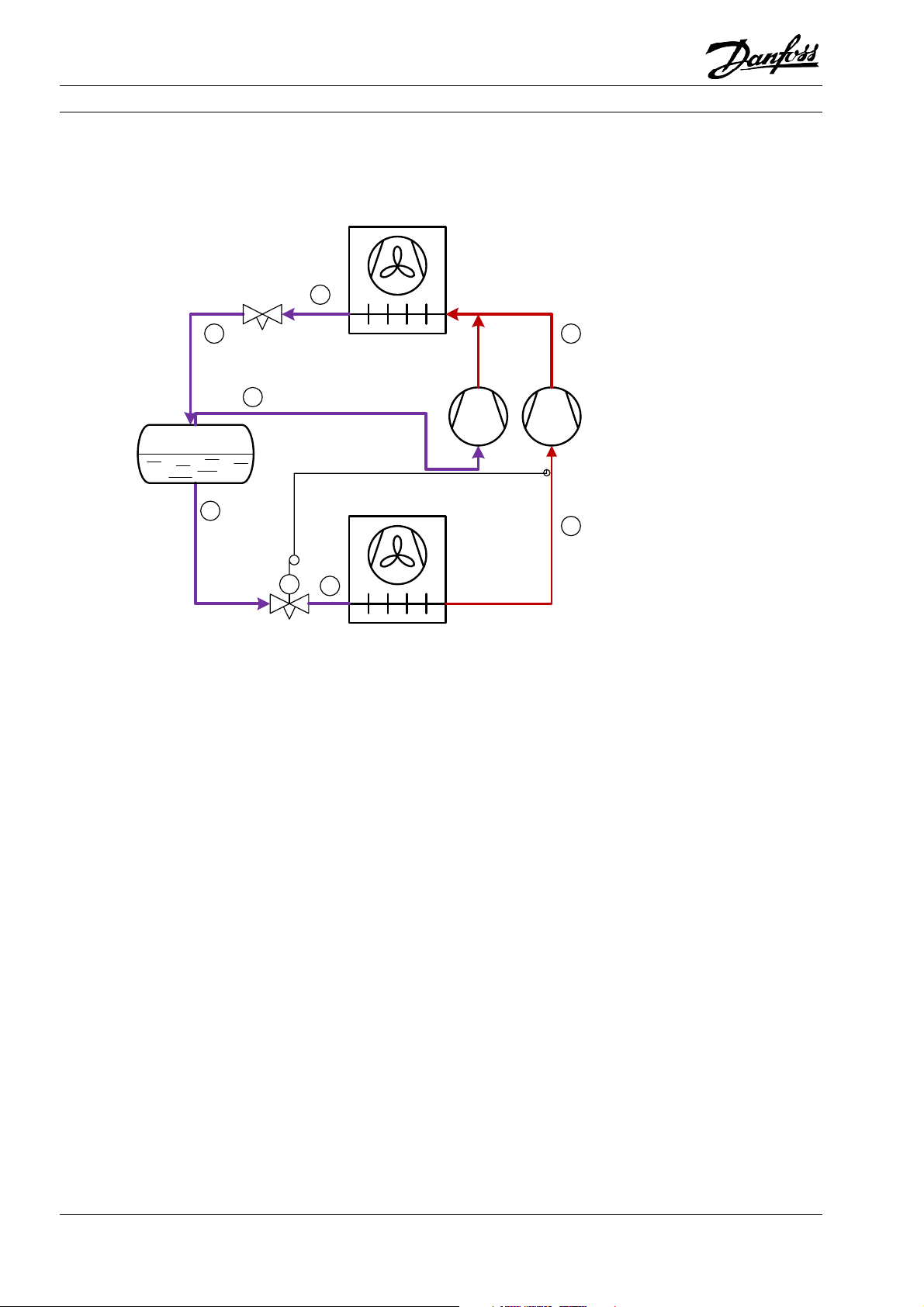
Figure 1.8: Cascade system diagram
A system diagram for a cascade system is shown in
Figure 1.8. The cascade system diagram is somewhat
similar to the two-stage system, where the interstage cooler is replaced by a cascade cooler, thus
making two closed cycles. A cascade system is usually more complex than a two-stage system, but it
offers some benefits. CO2 is very efficient down to
very low evaporating temperatures where ammonia‘s efficiency drops, while ammonia can condense
at relatively low pressure against warm ambient
temperatures, where CO2 has to go transcritical
where the efficiency drops. So, choosing CO2 in the
LP circuit and ammonia in the HP circuit allows for
the best of both worlds.
Oil Cooler
LP Compressor
1
2
Evaporator
4
Expansi on valve
3
5
HP Compressor
Cascade cooler
8
7
Oil Separator
6
Condenser
Economizer
12 AB13778641621700-000702 © Danfoss A/S (RC-MDP/MWA), 2020-10
Page 15

Application Handbook Industrial Refrigeration ammonia and CO2 applications
1.6 Transcritical systems
The properties of CO2 make it necessary to operate
the system in a different way. The ‘critical point’ –
the top of the bell-shaped two-phase area – is at
31°C / 72.8 bara. In areas/periods where the ambient temperature is low, CO2 can be operated with
condensing below the critical point. In that case the
cycle is, in principle, the same as for other refrigerants (different pressures and enthalpies), but if the
ambient temperature is relatively high, it is no
longer possible to condense in the traditional way.
Figure 1.9: Log(p)-h diagram for transcritical CO2 system
Above the critical point, the refrigerant is called a
transcritical fluid. The transcritical fluid does not
condense, but rather displays a gradual change of
density as it is cooled. In a traditional condensing
process, the condensing temperature defines the
pressure, but in the transcritical fluid there is no
such connection. Thus, the gas cooling pressure
(equal to compressor discharge pressure) needs to
be controlled.
© Danfoss A/S (RC-MDP/MWA), 2020-10 AB13778641621700-000702 13
Page 16

Application Handbook Industrial Refrigeration ammonia and CO2 applications
Evaporation takes place from (4) to (1) and
compression from (1) to (2) as in other refrigeration
systems. From (2) to (3) is the ‘gas cooling’ process
that replaces the condensing process. Point (3) is
defined by the outlet temperature of the gas cooler
– here set to 40°C – and the pressure that is
controlled by the expansion device that expands to
(4). The actual pressure in the gas cooler is based on
an analysis of the cycle. Consider a case where the
gas cooler outlet is at 40°C, but different pressures
are controlled. The corresponding cycles are as
shown below:
Figure 1.10: Log(p)-h diagram for a transcritical CO2 system at different gas cooler pressures
The cooling capacity of the system is the enthalpy
difference between points (1) and (4) multiplied by
the mass flow. The necessary compression power is
the enthalpy difference between points (2) and (1)
(horizontally) multiplied by the mass flow. The COP
of the system is thus (H1-H4)/(H2-H1), which is independent of the mass flow. It can be seen that if the
pressure is varied up (red) or down (blue), both the
cooling capacity and power consumption change.
Calculating the COP along the (red) temperature
curve, it can be found to have a maximum at a specific pressure, which for 40°C works out to be 102.4
bar. Mapping this maximum COP across different gas
cooler exit temperatures has resulted in a curve that
expresses the best pressure for a given gas cooler
exit temperature. This curve has been implemented
in the Danfoss EKC 326 controller.
Controlling the gas cooler pressure with the expansion device results in a problem. Since it is intended
that the low-pressure side be supplied with the right
amount of liquid – especially with DX operation of
the low-pressure evaporators – it is simply not possible to have an expansion valve serve both purposes
at once.
14 AB13778641621700-000702 © Danfoss A/S (RC-MDP/MWA), 2020-10
Page 17
Application Handbook Industrial Refrigeration ammonia and CO2 applications
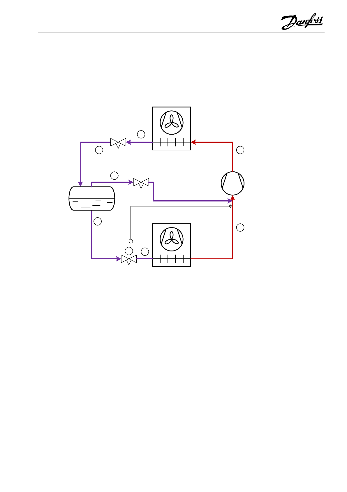
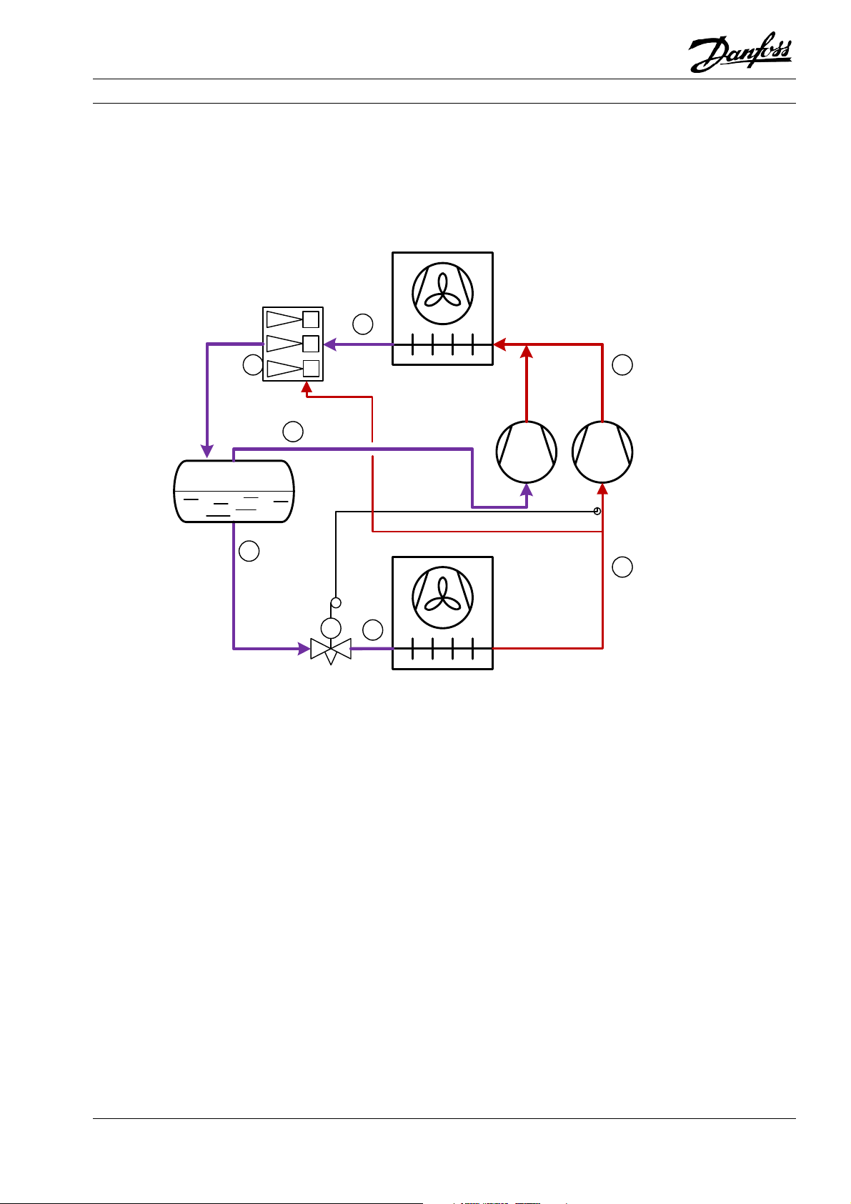
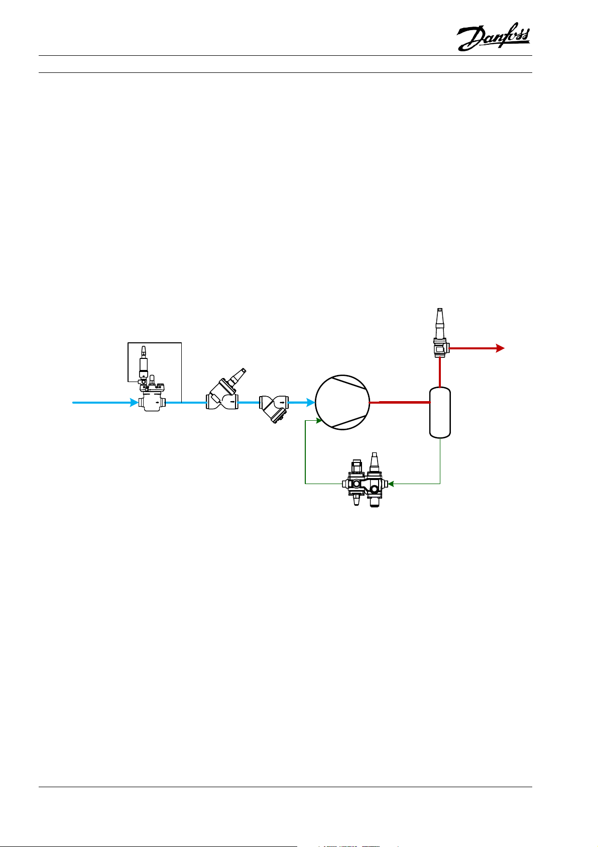
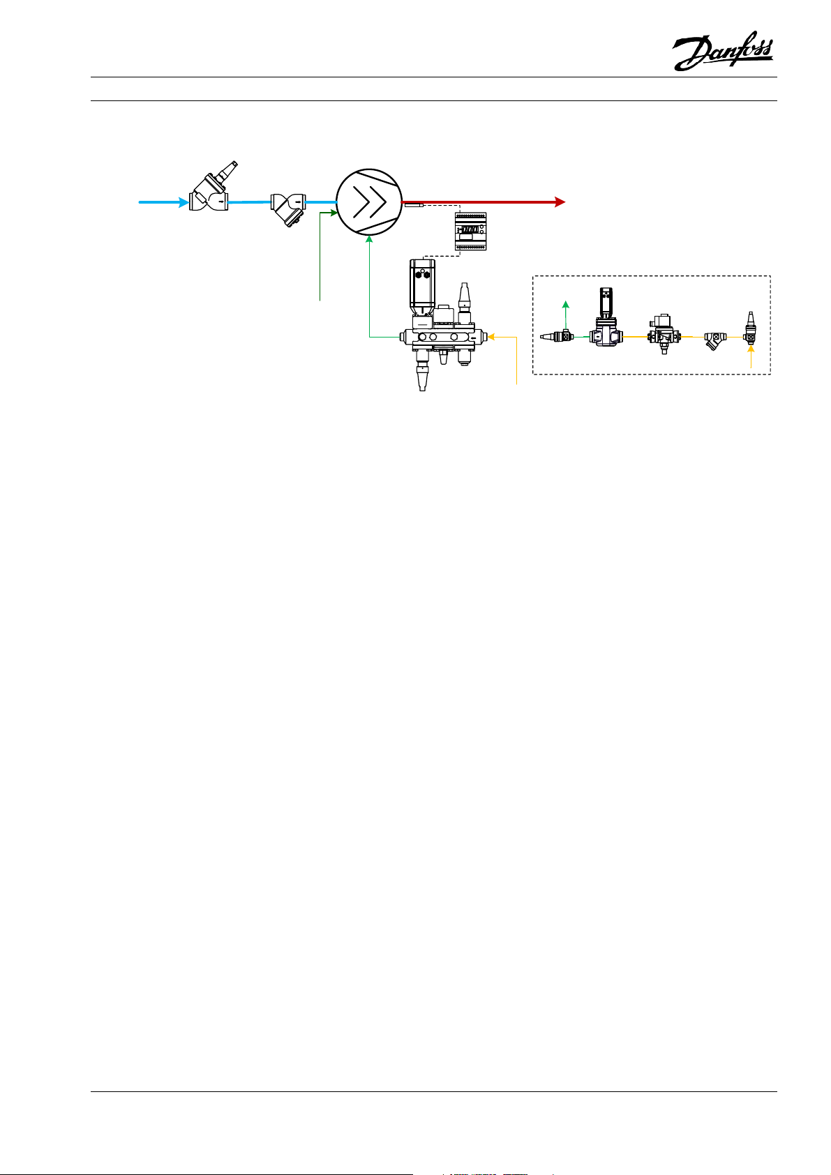
The solution is to make an intermediate stop in the
form of a receiver. The transcritical fluid is flashed
from the gas cooler exit through the high-pressure
valve into the receiver. In the receiver, the gas and
the evaporators as necessary, while the gas part is
reduced in pressure and fed to the compressor’s suc-
tion line, thereby controlling the pressure in the re-
ceiver.
liquid part is separated, the liquid part is flashed to
Figure 1.11: Transcritical CO2 system with intermediate pressure receiver
3
4
5
Receiver
Gas cooler
2
6
1
TC
7
Figure 1.12: Log(p)-h diagram for a transcritical CO2 system with intermediate pressure receiver
© Danfoss A/S (RC-MDP/MWA), 2020-10 AB13778641621700-000702 15
Page 18
Application Handbook Industrial Refrigeration ammonia and CO2 applications
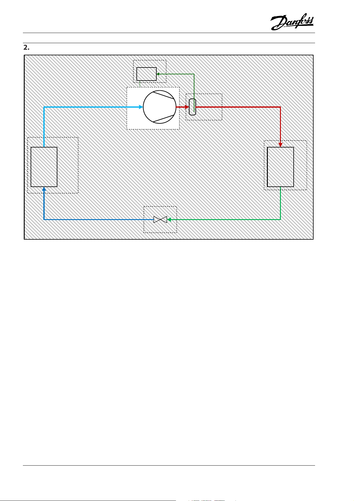
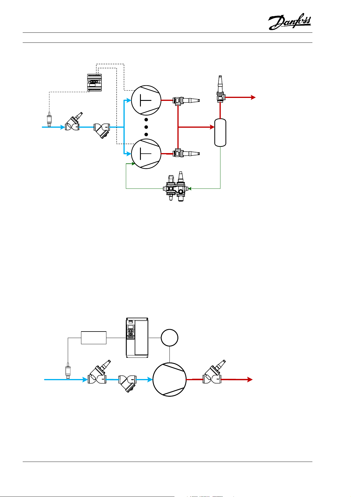
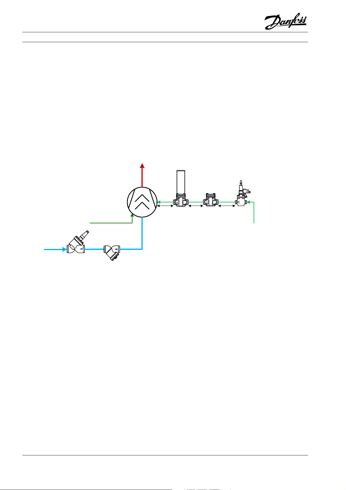
This process can be optimised. The gas from the receiver is reduced in pressure to the compressor suction, however it is possible to take advantage of the
compressor to compress this gas to gas cooler pressure with a higher efficiency due to the higher suc-
tion pressure. This is called parallel compression.
higher pressure in the receiver to employ another
Figure 1.13: Transcritical CO2 system with parallel compression
3
4
5
Receiver
6
Gas cooler
2
1
TC
7
Figure 1.14: log(P)-h diagram for a transcritical CO2 system with parallel compression
16 AB13778641621700-000702 © Danfoss A/S (RC-MDP/MWA), 2020-10
Page 19
Application Handbook Industrial Refrigeration ammonia and CO2 applications
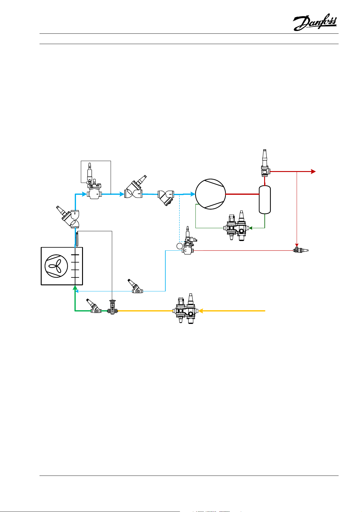
One further optimisation for CO2 transcritical systems is the use of ejectors. Ejectors utilise the power
in the expansion from gas cooler pressure to lift a
gas flow to a higher pressure. One of several differ-
ent ways of employing this is to lift part of the suction gas from the low-stage compressor to the suction of the parallel compressor, resulting in an efficiency gain.
Figure 1.15: Transcritical CO2 system with parallel compression and gas ejectors
3
4
5
Receiver
Gas cooler
2
6
1
TC
7
© Danfoss A/S (RC-MDP/MWA), 2020-10 AB13778641621700-000702 17
Page 20
Application Handbook Industrial Refrigeration ammonia and CO2 applications
Compressor controls
Oil Cooler
Oil Separator
Compressor
Evaporator
Expansion valve
The compressor is the “heart” of the refrigeration
system. It has two basic functions:
Maintain the pressure in the evaporator so that the
liquid refrigerant can evaporate at the required temperature.
Compress the refrigerant so that it can be condensed at a higher temperature.
Condenser
If the compressor capacity is greater than the de-
mand, the evaporating pressure and temperature
will be lower than that required, and vice versa.
Additionally, the compressor should not be allowed
to operate outside of the approved operation enve-
lope for the mechanical safety of the compressor
and operational safety of the entire system.
The basic function of compressor control, therefore,
is to adjust the capacity of the compressor to the actual demand of the refrigeration system so that the
required evaporating temperature can be maintained.
18 AB13778641621700-000702 © Danfoss A/S (RC-MDP/MWA), 2020-10
Page 21
Application Handbook Industrial Refrigeration ammonia and CO2 applications
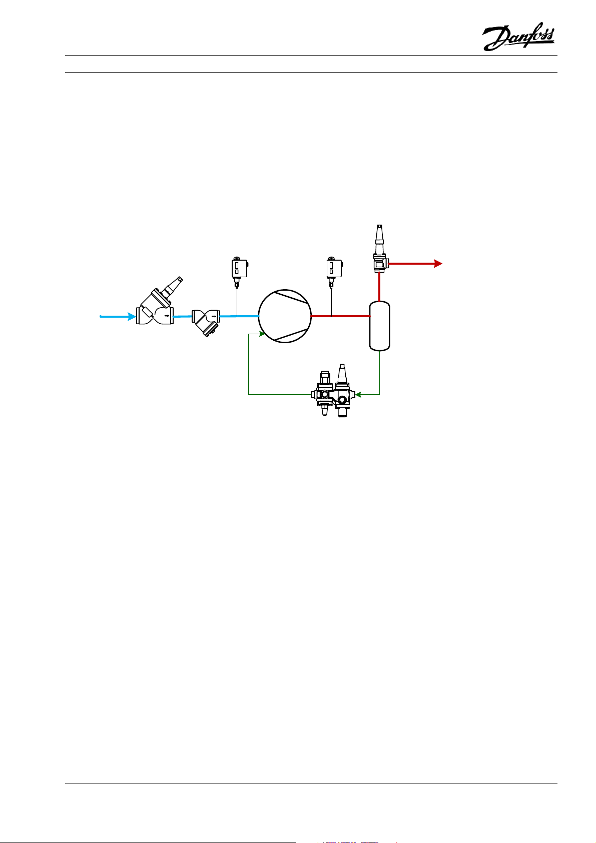
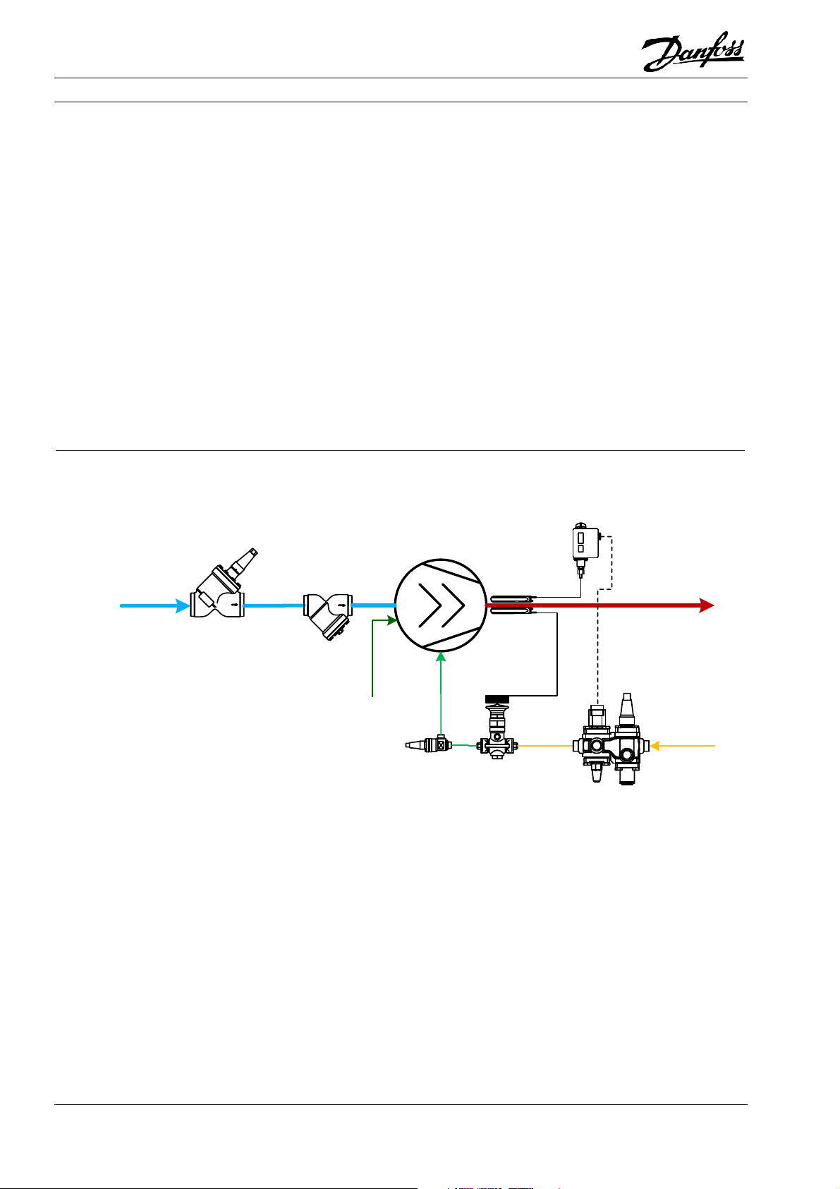
2.1 Reverse flow control
Reverse flow and condensation of refrigerant during
stand-still from the condenser to the oil separator
and the compressor should be avoided at all times.
For piston compressors, reverse flow can result in
liquid hammering. For screw compressors, reverse
Application Example 2.1.1: Reverse flow control
RT 1A RT 5A
Compressor
From evaporator/
liquid separator
SVA
FIA
flow can cause reversed rotation and damage to the
compressor bearings. To avoid this reverse flow, it is
necessary to install a check valve on the outlet of the
oil separator.
SCA
To condenser
Oil
Separator
ICFS
ICFE
The stop check valve SCA can function as a check
valve when the system is running and can also shut
off the discharge line for service as a stop valve. This
combined stop/check valve solution is easier to install and has lower flow resistance compared to a
normal stop valve plus check valve installation.
When selecting a stop check valve, it is important to:
Select a valve according to the capacity and not the
pipe size.
Consider both the nominal and part-load working
conditions. The velocity in the nominal condition
should be close to the recommended value, while at
the same time, the velocity in the part-load condition should be higher than the minimum recommended velocity.
ICFF
ICFO
ICF
Pressure switches RT 1A and RT 5A are shown in the
suction line and discharge line of the compressor. It
is important to have pressure switches to cut-out or
cut-in operation if the pressure fluctuates outside
the operational range in the suction and discharge
line. Not all compressors are delivered with built-in
controls and safety switches, therefore the RT 1A
and RT 5A are shown. The pressure switches are not
shown for all application examples, but they should
always be present in the system. Often these
switches are part of the compressor package.
For details on how to select valves, please refer to
the product catalogue and use the Danfoss software
tool Coolselector2 for sizing the valve according to
the system capacity.
© Danfoss A/S (RC-MDP/MWA), 2020-10 AB13778641621700-000702 19
Page 22
Application Handbook Industrial Refrigeration ammonia and CO2 applications
2.2 Suction pressure control
During start-up or after defrosting, the suction pressure needs to be controlled, otherwise it may be too
high, and the compressor motor will be overloaded.
The electric motor for the compressor may be damaged by this overloading.
There are two ways to overcome this problem:
Start the compressor at part load. The capacity control methods can be used to start the compressor at
part load, e.g. unload part of the pistons for multi-
Application example 2.2.1: Crankcase pressure control
CVC
piston reciprocating compressors, or bypass some
suction gas for screw compressors with slide valves,
etc.
Control the suction pressure for reciprocating com-
pressors. By installing a back pressure-controlled
regulating valve in the suction line, which will not
open until the pressure in the suction line drops be-
low the set value, suction pressure can be kept un-
der a certain level.
SCA
To condenser
Compressor
From evaporator/
liquid separator
ICS
SVA
In order to control the suction pressure during startup, after defrosting, or in other cases when the suction pressure may be too high, the pilot-operated
servo valve (ICS) with the back pressure controlled
pilot valve (CVC) is installed in the suction line. The
Oil
Separator
FIA
ICFS
ICFE
ICFF
ICFO
ICF
ICS will not open until the downstream suction pres-
sure falls below the set value of the pilot valve (CVC).
In this way, the high-pressure vapour in the suction
line can be released into the compressor gradually,
which ensures a manageable capacity for the com-
pressor motor.
20 AB13778641621700-000702 © Danfoss A/S (RC-MDP/MWA), 2020-10
Page 23

Application Handbook Industrial Refrigeration ammonia and CO2 applications
2.3 Compressor capacity control
The compressor in a refrigeration system is normally
selected to be able to satisfy the highest possible
cooling load. However, the cooling load during normal operation is usually lower than the design cooling load. This means that it is always necessary to
control the compressor capacity so that it matches
the actual cooling load. There are several common
ways to control the compressor capacity:
2.3.1 Step control
This means to unload cylinders in a multi-cylinder
compressor, to open and close the suction ports of a
screw compressor, or to start and stop some compressors in a multi-compressor system. This system
is simple and convenient. Furthermore, efficiency
decreases very little during part-load by step control,
although this regulation is by nature coarser than
many other regulation types. It is especially applicable to systems with several multi-cylinder reciprocating compressors.
2.3.2 Slide valve control
The most common device used to control the capacity of a screw compressor is the slide valve. The action of the oil-driven slide valve allows part of the
suction gas to avoid being compressed. The slide
valve permits a smooth and continuous modulation
of capacity from 100% down to 10%, but the efficiency drops at part load, usually quite significantly.
2.3.3 Variable speed control
This solution is applicable to all kinds of compressors
and is efficient. A two-speed electric motor or a frequency converter can be used to vary the speed of
the compressor. The two-speed electric motor regulates the compressor capacity by running at the high
speed when the cooling load is high (e.g. cooling
down period) and at the low speed when the cooling
load is low (e.g. storage period). The frequency converter can vary the rotation speed continuously to
satisfy the actual demand. The frequency converter
observes limits for min. and max. speed, temperature and pressure control, protection of compressor
motor as well as current and torque limits. Frequency converters offer a low start-up current. Variable speed control usually has little impact on the efficiency of the compressor and is thus a very popular
control. In some cases, the range of allowed RPM of
the compressor is not enough to cover the desired
range of capacities, so often variable speed control is
combined with step control.
2.3.4 Hot gas bypass
This solution is applicable to compressors with fixed
capacities and more typical for commercial refrigeration. In industrial refrigeration systems it is used as a
safety measure to avoid an excessively low suction
pressure when there is a sudden drop in cooling
load. To control the refrigeration capacity, part of
the hot gas flow in the discharge line is bypassed
into the low-pressure circuit. This works as a fast response to a sudden drop in cooling load, thus adding
extra cooling load to the system when the compressor is ramping down. This generally decreases the efficiency of the system.
© Danfoss A/S (RC-MDP/MWA), 2020-10 AB13778641621700-000702 21
Page 24
Application Handbook Industrial Refrigeration ammonia and CO2 applications
Application example 2.3.1: Step control of compressor capacity
Compressor
pack
EKC 331
AKS 33
FIA
From evaporator/
liquid separator
SVA
A step control solution for compressor capacity can
be achieved by using a step controller, e.g. Danfoss
EKC 331. EKC 331 is a four-step controller with up to
four relay outputs. It controls the loading/unloading
of the compressors/pistons or the electric motor of
the compressor according to the suction pressure
SCA
To condenser
Oil
Separator
ICFO
ICFE
SCA
SCA
ICFS
ICFF
ICF
signal from a pressure transmitter, e.g. Danfoss AKS
33. Based on a neutral zone control, EKC 331 can
control a pack system with up to four equally sized
compressor steps or, alternatively, two capacity-con-
trolled compressors (each with one unload valve).
Application example 2.3.2: Variable speed capacity control
VLT
Controller
AKS 33
FIA
From evaporator/
liquid separator
22 AB13778641621700-000702 © Danfoss A/S (RC-MDP/MWA), 2020-10
SVA
M
Compressor
SVA
To oil separator
Page 25
Application Handbook Industrial Refrigeration ammonia and CO2 applications
The VLT frequency converter is controlled by a controller module that adjusts the control signal to the
converter from an input signal from a pressure
transmitter, e.g. AKS 33. The controller module can
be either a Danfoss AK-CC or a PLC/OEM module.
The VLT frequency converter can also receive the
signal from the pressure transmitter and work without a separate controller.
Application example 2.3.3: Hot gas bypass
CVC
ICS
SVA
SVA
FIA
Frequency converter control offer the following advantages:
Energy savings
Improved control and product quality
Noise reduction
Longer lifetime
Simplified installation
Easy-to-use complete control of the system
SCA
Compressor
ICFS
ICFE
CVC
EVM
1
ICFO
ICFF
ICF
To condenser
Oil
Separator
SVA
Evaporator
SVA
TEA
ICFE
ICFO
Hot gas bypass can be used in specific cases to compensate for a suddenly reduced cooling load. Normally in industrial refrigeration plants, the compressors will be speed controlled or step controlled.
These controls can, however, be too slow in reacting
in cases where there is a sudden drop in cooling
load. This sudden drop will initially cause the compressor to decrease the suction pressure. Hot gas bypass can be used as a fast response to a sudden decrease in cooling load, which will prevent the suction
pressure from dropping too low. The hot gas is bypassed to the evaporator until the compressor has
ramped down to match the reduced cooling load.
ICS SVA
ICFS
From receiver
ICFF
ICF
Hot gas bypass is energy inefficient and should not
be used as a primary solution to “control” the compressor, but rather as a safety measure to avoid excessively low suction pressure.
The pilot-operated servo valve ICS (1) with a CVC pilot valve is used to control the hot gas bypass flow
according to the pressure on the suction line. The
CVC is a back-pressure controlled pilot valve which
opens the ICS (1) and increases the flow of hot gas
when the suction pressure is below the set value. In
this way, the suction pressure ahead of the compressor is kept constant, and thus the refrigeration capacity satisfies the actual cooling load.
© Danfoss A/S (RC-MDP/MWA), 2020-10 AB13778641621700-000702 23
Page 26
Application Handbook Industrial Refrigeration ammonia and CO2 applications
2.4 Discharge Temperature Control with Liquid Injection
Compressor manufacturers generally recommend
limiting the discharge temperature below a certain
value to prevent overheating of the compressor and
its parts, prolonging their life and preventing the
breakdown of oil at high temperatures.
There are several ways to reduce the discharge tem-
perature. One way is to install water-cooled heads in
reciprocating compressors. Another method is liquid
injection, which involves liquid refrigerant from the
outlet of the condenser or receiver being injected
into the suction line, the intermediate cooler beReferring to the log p-h diagram in chapter 1, it can
be seen that the discharge temperature may be high
tween compressors, or the side port of the screw
compressor.
when:
the compressor runs with high pressure differential.
the compressor receives highly superheated suction
vapour.
the compressor runs with capacity control by hot gas
bypass.
Application example 2.4.1: Liquid injection with thermostatic injection valve
Screw compressor
RT 107
From evaporator/
liquid separator
SVA
FIA
Oil injection
When the discharge temperature rises above the set
value of the thermostat RT 107, RT 107 will energize
the solenoid valve ICFE which will start liquid injection into the side port of the screw compressor. The
To oil
Separator
ICFS
ICFE
SVA
TEAT
ICFO
ICFF
From
receiver
ICF
thermostatic injection valve (TEAT) controls the in-
jected liquid flow according to the discharge temper-
ature, which prevents the discharge temperature
from rising further.
24 AB13778641621700-000702 © Danfoss A/S (RC-MDP/MWA), 2020-10
Page 27
Application Handbook Industrial Refrigeration ammonia and CO2 applications
Application example 2.4.2: Liquid injection with motor valve
Screw compressor
To oil
Separator
From evaporator/
liquid separator
SVA
FIA
AKS 21
EKC 361
ICAD
Oil injection
ICM
An electronic solution for liquid injection control can
be achieved with the motorized valve ICM. An AKS
21 temperature sensor will register the discharge
temperature and transmit the signal to the temperature controller EKC 361.
ICFS
ICFO
ICFE
ICF
ICFS
ICFF
From
receiver
SVA
ICAD
ICM
Single component solution
EVRA
The EKC 361 controls the ICAD actuator which adjusts the opening degree of the ICM motor valve in
order to limit and maintain the required discharge
temperature.
SVA
FIA
© Danfoss A/S (RC-MDP/MWA), 2020-10 AB13778641621700-000702 25
Page 28
Application Handbook Industrial Refrigeration ammonia and CO2 applications
2.5 Economizer damper
An economizer is used to increase system capacity
and efficiency.
Pulsations need to be dampened to avoid compo-
nent damage. Correct and well considered dimen-
sioning of economizer lines is necessary to reduce
However, pulsations from the compressor are trans-
ferred into the economizer line which damages components and leads to valve chattering. The pulsations will lead to increased maintenance costs and
downtime if they are not taken care of.
pulsations. The Danfoss Eco-Damper combines three
components into a high-impact solution which re-
duces pulsations significantly and ensures high oper-
ational reliability thanks to its solid design. The
Danfoss Eco-Damper is based on the Danfoss ICV
platform.
Application example 2.5.1: Economizer line pulsation damping solution
To oil
Separator
Screw compressor
Max 150 mm
Oil injection
Max 150 mm Max 150 mm
ICD ICC
EVMCVP
ICS
From economizer
vessel
From evaporator/
liquid separator
SVA
FIA
The Danfoss Eco-damper solution consists of 3 components. The Eco-damper (ICD), the Eco-check valve
(ICC) and a standard control valve, e.g. an ICS servo
valve with CVP, constant pressure pilot valve, and
the EVM solenoid valve. The combination shown in
the application example can dampen the pulsations
by up to 80% and prevent premature failure of economizer components and reduce system downtime.
The Eco-damper solution unit has a unique broadband damping effect in the 100-500 Hz working
range.
Support on pipe segments is essential to reduce the
pulsations and thus reduce vibrations induced by the
pulsations. Therefore, each pipe segment between
the components in the Eco-damper solution must be
fixed to a pipe support element which can absorb
the pulsations. The tube on the Eco-damper (ICD)
must also be fixed to a pipe support element that
can absorb the pulsations.
The ICD Eco-damper comes with an integrated
strainer, and is applicable for ammonia systems,
along with R134a and R407C systems.
The ICC Eco-check valve has a solid design and is fully
opening at low differential pressure to prevent oscil-
lating movements. The ICC Eco-check valve is appli-
cable for ammonia, CO2 and HFC systems.
For less severe or occasional pulsation issues, the ro-
bust Eco-check valve (ICC) and the control valve can
be used without an Eco-damper (ICD). Note! In this
case, the pulsations from the compressor eco-port
will not be damped.
It is recommended to have a maximum pipe length
of 150 mm between the individual components and
between the ICD and the economizer port in the
compressor.
26 AB13778641621700-000702 © Danfoss A/S (RC-MDP/MWA), 2020-10
Page 29
Application Handbook Industrial Refrigeration ammonia and CO2 applications
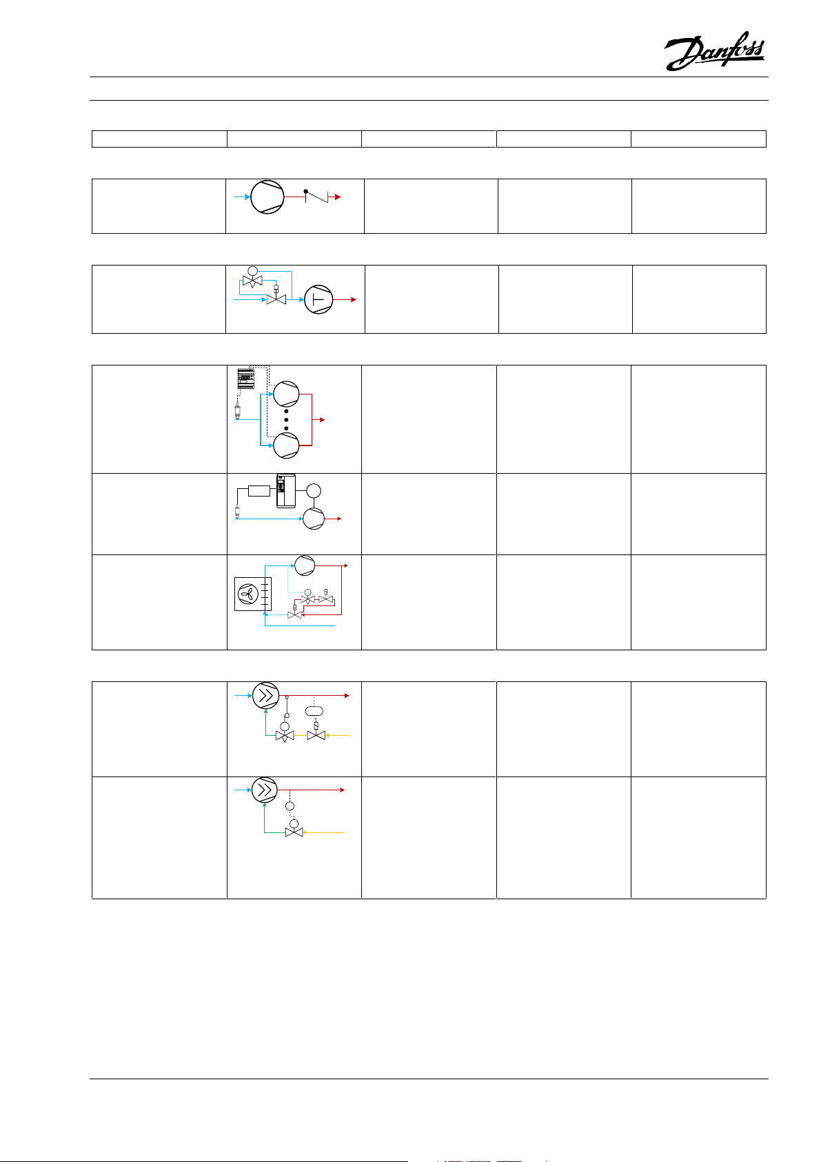
2.6 Summary
Solution Application Benefit Limitations
Reverse Flow Control – see section 0
Reverse flow control with
SCA
Applicable to all
refrigeration plants.
Crankcase Pressure Control – see section 2.2
Crankcase pressure
control with ICS and CVC
PC
Applicable to
reciprocating
compressors, normally
used for small and
medium systems.
Compressor Capacity Control – see section 2.3
Step control of
compressor capacity with
EKC 331 and AKS 33
Compressor variable
speed capacity control
Hot gas bypass using ICS
and CVC
Controller
M
PC
Applicable to multicylinder compressor,
screw compressor with
multiple suction ports,
and systems with several
compressors running in
parallel.
Applicable to all
compressors with the
ability to run at reduced
speed.
Applicable to
compressors with fixed
capacities. Used as safety
measure against
excessively low suction
pressure
Discharge Temperature Control with Liquid Injection – see section 0
Simple.
Easy to install.
Low flow resistance.
Simple and reliable.
Effective in protecting
reciprocating
compressors on start-up
or after hot gas defrost.
Simple.
Almost as efficient at part
load as at full load.
Low start-up current
Energy savings
Lower noise
Longer lifetime
Simplified installation
Fast response to sudden
drops in cooling load. The
hot gas can help the oil
return from the
evaporator.
Causes constant pressure
drop in the discharge
line.
Causes constant pressure
drop in the suction line.
The control is not
continuous, especially
when there are only a few
steps. Fluctuations in the
suction pressure.
Compressor must be
suited for reduced speed
operation.
Should not be used as
primary compressor
capacity control. Energy
inefficient.
Mechanical solution for
liquid injection with TEAT,
EVRA(T) and RT
Electronic solution for
liquid injection control
with EKC 361 and ICM/ICF
Applicable to systems
TSHL
TC
where the discharge
temperatures may run
too high.
Simple and effective.
Injection of liquid
refrigerant may be
dangerous to the
compressor. Not as
efficient as intermediate
cooler.
Applicable to systems
TC
M
where the discharge
temperatures may run
too high.
Flexible and compact.
Possible to monitor and
control remotely.
Not applicable to
flammable refrigerants.
Injection of liquid
refrigerant may be
dangerous to the
compressor. Not as
efficient as intermediate
cooler.
© Danfoss A/S (RC-MDP/MWA), 2020-10 AB13778641621700-000702 27
Page 30
Application Handbook Industrial Refrigeration ammonia and CO2 applications
Condenser controls
Oil Cooler
Oil Separator
Compressor
Evaporat or
Expansi on valve
In areas where there are large variations in ambient
air temperatures and/or load conditions, it is necessary to control the condensing pressure to prevent it
from falling too low. Excessively low condensing pressures result in there being insufficient pressure differential across the expansion device and the evaporator not being supplied with enough refrigerant. It
means that condenser capacity control is mainly
used in the temperate climate zones and to a lesser
degree in subtropical and tropical zones.
The basic idea of condensing capacity control is to
control the condenser capacity when the ambient
temperature is low, so that the condensing pressure
is maintained above the minimum acceptable level
and to keep the condensing pressure as low as possible for optimal efficiency. This condensing capacity
control is achieved either by regulating the flow of
circulating air or water through the condenser, or by
reducing the effective heat exchanger surface area.
Different solutions can be designed for different
types of condensers:
Air cooled condensers
Condenser
Condenser installation depends on the way injection
to the low-pressure side of the refrigeration system
is controlled. Note that the terms ‘high-pressure
float valve operation’ and ‘low-pressure float valve
operation’ refer to the mode of operation, not spe-
cifically the use of a float valve. Both operation
modes can be achieved by using level
switches/transmitters and a normal expansion valve.
3.1 High-pressure float valve operation
High-pressure float valve operation is expansion of
the liquid immediately after the condenser. Any vari-
ation in the charge volume due to variations in ca-
pacity must be handled at the low-pressure side, e.g.
in a liquid separator. Since the flow after the expan-
sion valve is two-phase, it is not suitable for distribu-
tion to more than one location and thus it is primar-
ily used in systems with only one low-pressure sepa-
rator, such as a chiller unit.
High-pressure float valves are usually mounted im-
mediately after the condenser and, as such, pose no
special problems with regard to condenser installa-
tion.
Evaporative condensers
Water cooled condensers
28 AB13778641621700-000702 © Danfoss A/S (RC-MDP/MWA), 2020-10
Page 31

Application Handbook Industrial Refrigeration ammonia and CO2 applications
3.2 Low-pressure float valve operation
Low-pressure float valve operation controls the expansion of the condensed liquid to keep a given level
in one or more low-pressure separators. Any varia-
3.3 Air-cooled condensers
An air-cooled condenser consists of tubes mounted
within a fin block. The condenser can be horizontal,
vertical or V-shaped. The ambient air is drawn across
the heat exchanger surface with axial or centrifugal
fans.
3.3.1 Step control of air-cooled condensers
This method utilizes a step controller to control the
air flow in the air-cooled condenser by switching the
fans on or off according to a condensing pressure
signal.
tion of the charge volume due to variations in capacity must be handled on the high-pressure side, e.g. in
a receiver.
To ensure proper functioning of a condenser in a
low-pressure float valve system, the installation
must be correct.
Air-cooled condensers are used on industrial refrigeration systems where the relative air humidity is
high. Air-cooled condenser application examples are
depicted below as low-pressure float valve operation.
Controlling the condensing pressure for air-cooled
condensers can be achieved in the following ways:
A pressure transmitter, e.g. Danfoss AKS 33,
measures the condensing pressure and sends a signal to a step controller, e.g. Danfoss EKC 331, which
controls the switching of the fans according to the
pressure signal.
3.3.2 Fan speed control of air-cooled condensers
This method of condenser fan control is mainly used
when a reduction in noise level is desired due to environmental concerns.
3.3.3 Area control of air-cooled condenser
For area control of air-cooled condensers, a receiver
is required. This receiver must have sufficient volume to be able to accommodate the variations in
the amount of refrigerant in the condenser.
There are two ways this condenser area control can
be done:
The main valve ICS combined with the constant pressure pilot CVP-H (high-pressure) mounted in the discharge line on the inlet side to the condenser and
ICS combined with a differential pressure pilot CVPP
mounted in the pressure equalization line between
the discharge line and the receiver. In the pipe between the condenser and the receiver, a stop-check
valve SCA is mounted to prevent liquid migration
from the receiver to the condenser.
For this type of installation, Danfoss frequency converter VLT can be used.
Main valve ICS combined with the constant pressure
pilot CVP-H mounted in the pipe between the condenser and the receiver and an ICS combined with a
differential pressure pilot CVPP mounted in the pressure equalization line between the discharge line
and the receiver. This method is mainly used in commercial refrigeration.
© Danfoss A/S (RC-MDP/MWA), 2020-10 AB13778641621700-000702 29
Page 32

Application Handbook Industrial Refrigeration ammonia and CO2 applications
Application Example 3.3.1: Air flow control of air-cooled condenser with step controller EKC 331
EKC 331
AKS 33
From
discharge line
SVA
LLG
SVA
To oil cooler
EKC 331 is a four-step controller with up to four relay outputs. It controls the switching of the fans according to the condensing pressure signal from a
pressure transmitter AKS 33.
Based on neutral zone control, EKC 331 can control
the condensing capacity so that the condensing pressure is maintained above the required minimum
level.
The bypass pipe (thin red line) where SVA is installed
is an equalizing pipe, which helps balance the pressure in the receiver with the inlet pressure of the
condenser so that the liquid refrigerant in the condenser can be drained into the receiver.
It is important to account for the pressure drop in
the condenser when designing the piping from the
condenser to the receiver. The pressure at the outlet
of the condenser can be lower than the pressure in
the receiver, which will restrict the flow to the receiver. Using a drop leg between the condenser and
Condenser
SVA
SNV
SFASFA
DSV
Receiver
SCA
To expansion device
h
Liquid trap
Priority for oil cooler
receiver with a liquid trap at the bottom will allow
the build-up of liquid in the drop leg. The liquid col-
umn in the drop leg will provide a positive pressure
to counter the pressure drop in the condenser. The
height of the drop leg must be larger than the pres-
sure loss in the condenser, expressed in metres of
liquid. In some installations, EKC 331T is used. In this
case, the input signal could be from a PT 1000 tem-
perature sensor, e.g. AKS 21. The temperature sen-
sor is usually installed in the outlet of the condenser.
Note! The EKC 331T + PT1000 temperature sensor
solution is not as accurate as the EKC 331 + pressure
transmitter solution, because the condenser outlet
temperature may not entirely reflect the actual con-
densing pressure due to the liquid subcooling or the
presence of incondensable gasses in the refrigera-
tion system. If the subcooling is too low, flash gas
may occur when the fans start.
30 AB13778641621700-000702 © Danfoss A/S (RC-MDP/MWA), 2020-10
Page 33

Application Handbook Industrial Refrigeration ammonia and CO2 applications
Application Example 3.3.2: Fan speed control of air-cooled condenser
VLT
From
discharge line
AKS
SVA
LLG
SVA
To oil cooler
The VLT frequency converter is controlled by the
condensing pressure signal from a pressure transmitter, e.g. Danfoss AKS 33, on the discharge line. The
VLT frequency converter adjusts the speed of the
fans in the air-cooled condenser according to the signal from the pressure transmitter.
Frequency converter control offers the following advantages:
Energy savings
Improved control and product quality
Noise reduction
Longer lifetime
Simplified installation
Condenser
SVA
SNV
Receiver
To expansion device
SFASFA
DSV
SCA
h
Liquid trap
Priority for oil cooler
It is important to account for the pressure drop in
the condenser when designing the piping from the
condenser to the receiver. The pressure at the outlet
of the condenser can be lower than the pressure in
the receiver, which will restrict the flow to the receiver. Using a drop leg between the condenser and
receiver, with a liquid trap at the bottom, will allow
the build-up of liquid in the drop leg. The liquid column in the drop leg will provide a positive pressure
to counter the pressure drop in the condenser. The
height of the drop leg must be greater than the pressure loss in the condenser, expressed in metres of
liquid.
Easy-to-use complete control of the system
© Danfoss A/S (RC-MDP/MWA), 2020-10 AB13778641621700-000702 31
Page 34

Application Handbook Industrial Refrigeration ammonia and CO2 applications
Application Example 3.3.3: Area control of air-cooled condenser (for cold climates)
CVP
Suction
line
SVA
LLG
To oil cooler
ICS
SVA
ICS
CVPP
SVA
SVA
SFASFA
SNV
DSV
Receiver
To expansion device
Condenser
h
SCA
Liquid trap
Priority for oil cooler
This regulating solution maintains the pressure in
the receiver at a sufficiently high level during low
ambient temperatures.
The ICS pilot-operated servo valve in the discharge
line opens when the discharge pressure reaches the
set pressure on the CVP pilot valve and closes when
the pressure drops below the set pressure of the
CVP pilot valve.
The ICS pilot-operated servo valve with the CVPP
constant differential pressure pilot in the pressure
equalization line (thin red line) maintains sufficient
pressure in the receiver.
The SCA stop-check valve ensures increased condenser pressure by liquid back-up within the condenser.
This requires a sufficiently large receiver. The SCA
stop-check valve also prevents liquid flow from the
receiver back into the condenser when the latter is
colder during compressor shut-down periods.
It is important to account for the pressure drop in
the condenser when designing the piping from the
condenser to the receiver. The pressure at the outlet
of the condenser can be lower than the pressure in
the receiver, which will restrict the flow to the re-
ceiver. Using a drop leg between the condenser and
receiver, with a liquid trap at the bottom, will allow
the build-up of liquid in the drop leg. The liquid col-
umn in the drop leg will provide a positive pressure
to counter the pressure drop in the condenser. The
height of the drop leg must be greater than the pres-
sure loss in the condenser, expressed in metres of
liquid.
32 AB13778641621700-000702 © Danfoss A/S (RC-MDP/MWA), 2020-10
Page 35

Application Handbook Industrial Refrigeration ammonia and CO2 applications
3.4 Evaporative condensers
An evaporative condenser is a condenser cooled by
ambient air combined with water sprayed through
orifices and air baffles in counterflow with the air.
The water evaporates, and the evaporation effect of
the water drops adds considerably to the condenser
capacity, as the air is cooled to the ‘wet bulb’ temperature.
Today’s evaporative condensers are enclosed in a
steel or plastic enclosure with axial or centrifugal
fans at the bottom or at the top of the condenser.
The heat exchanger surface in the wet air stream
consists of steel pipes.
Above the water spray orifices (in the dry air) it is
common to have a de-superheater made of steel
pipes with fins to reduce the discharge gas temperature before it reaches the heat exchanger in the wet
air stream. In this way, the build-up of limescale on
the surface of the main heat exchanger pipes is reduced.
This type reduces the water consumption considerably compared to a normal water-cooled condenser.
Capacity control of an evaporative condenser can be
achieved by either a two-speed fan or variable speed
control of the fan and, at very low ambient temperature conditions, switching off the water circulation
pump.
The use of evaporative condensers is limited in areas
with high relative humidity. In cold surroundings
(ambient temperatures < 0°C), frost damage prevention must be carried out by removing the water in
the evaporative condenser.
The applications shown in this section are depicted
as low-pressure float valve operated.
3.4.1 Control of evaporative condensers
Controlling the evaporative condensers’ condensing
pressure or the condenser capacity can be achieved
in different ways:
RT or KP pressure controls for fan and water pump
control.
RT-L neutral zone pressure control for fan and water
pump control.
Step controller for controlling two-speed fans and the
water pump.
Frequency converters for fan speed control and water
pump control.
Saginomiya flow-switch for alarm if water circulation
fails.
© Danfoss A/S (RC-MDP/MWA), 2020-10 AB13778641621700-000702 33
Page 36

Application Handbook Industrial Refrigeration ammonia and CO2 applications
Application Example 3.4.1: Step control of evaporative condenser with pressure controller RT
Suction line
Compressor
SCA
RT 5A
LLG
To oil cooler
RT 5A
SVA
SVA
SVA
SNV
Condenser
SFASFA
DSV
Receiver
To expansion device
Water
pump
h
SCA
Liquid trap
Priority for oil cooler
This solution maintains the condensing pressure, as
well as the pressure in the receiver at a sufficiently
high level in low ambient temperatures.
When the inlet pressure of the condenser drops below the setting of the pressure controller RT 5A, the
controller will switch off the fan to decrease the condensing capacity.
In extremely low ambient temperatures, when the
condensing pressure drops below the setting of RT
5A after all the fans have been switched off, RT 5A
will stop the water pump.
When the pump is stopped, the condenser and the
water pipes should be drained to avoid scaling and
freezing.
34 AB13778641621700-000702 © Danfoss A/S (RC-MDP/MWA), 2020-10
Page 37

Application Handbook Industrial Refrigeration ammonia and CO2 applications
Application Example 3.4.2: Step control of evaporative condenser with step controller EKC 331
EKC 331
AKS 33
Suction line
Compressor
SCA
To oil cooler
LLG
SVA
SVA
SVA
SNV
Receiver
To expansion device
SFASFA
DSV
Condenser
SCA
Water
pump
h
Liquid trap
Priority for oil cooler
This solution works in the same way as Application
Example 3.4.1, but operated via step controller EKC
331.
A capacity regulation solution for evaporative con-
EKC 331T version can accept a signal from a PT 1000
temperature sensor, which may be necessary for
secondary systems.
densers can be achieved by using an EKC 331 power
regulator and an AKS 33 pressure transmitter. Sequential control for the water pump must be selected as the last step. Sequential control means that
the steps will always cut in and out in the same order.
Alternatively, a frequency converter can control the
condensing pressure by controlling the fan RPM,
possibly with a step function on individual fans, as in
the air cooled condenser version, with an RT 5A cutting out the pump at low condensing temperatures.
© Danfoss A/S (RC-MDP/MWA), 2020-10 AB13778641621700-000702 35
Page 38

Application Handbook Industrial Refrigeration ammonia and CO2 applications
3.5 Water-cooled condensers
In the past, the water-cooled condenser was typically a shell and tube heat exchanger, but today it is
very often a plate heat exchanger in a modern design.
Control of the condensing pressure can be achieved
using a pressure-controlled water valve, or a motor-
ized water valve controlled by an electronic control-
ler to control the flow of the cooling water according
to the condensing pressure.
Water-cooled condensers with open water loops are
not commonly used, because in many places it is not
permitted to use the large amount of water these
types consume (water shortage and/or high prices
for water). However, such restrictions usually do not
The applications shown in the following section are
depicted as high-pressure float valve operation.
Thus, no receiver is shown in the following applica-
tions.
apply in maritime applications.
Today, water-cooled condensers are popular in chillers, with the cooling water cooled by a cooling tower
and re-circulated. It can also be used as a heat recovery condenser to supply hot water.
Application Example 3.5.1: Water flow control of water-cooled condensers with a water valve
SCA
SVA
Suction line
Compressor
To expansion
SVA
device
This solution maintains the condensing pressure at a
constant level. The refrigerant condensing pressure
is directed through a capillary tube to the top of the
water valve WVS and adjusts the opening of WVS accordingly. The water valve (WVS) is a P-regulator.
SFA
SFA
SNV
DSV
Cooling water out
WVS
Cooling water in
Danfoss
SW-PHE
The condenser is shown as a Danfoss semi-welded
plate heat exchanger.
36 AB13778641621700-000702 © Danfoss A/S (RC-MDP/MWA), 2020-10
Page 39

Application Handbook Industrial Refrigeration ammonia and CO2 applications
Application Example 3.5.2: Water flow control of water-cooled condenser with a motor valve
Controller
AMV 20
SFA
SFA
AKS 33
SNV
DSV
SCA
SVA
Suction line
Compressor
To expansion
device
SVA
The controller receives the condensing pressure signal from the pressure transmitter AKS 33 and sends
out a corresponding modulating signal to actuator
AMV 20 of the motor valve VM 2. In this way, the
flow of cooling water is adjusted, and the condensing pressure is kept constant.
In this solution, PI or PID control can be configured in
the controller.
VM2
Cooling water in
Danfoss
SW-PHE
Cooling water out
VM 2 and VFG 2 are motor valves designed for district heating and can also be used for water flow
control in refrigeration plants.
Alternatively, an AB-QM pressure-independent balancing and control valve can be used. The AB-QM
valve consists of 2 functions: a differential pressure
controller and a control valve. The differential pressure controller maintains a constant differential
pressure across the control valve, while the control
valve adjusts the flow through the valve.
© Danfoss A/S (RC-MDP/MWA), 2020-10 AB13778641621700-000702 37
Page 40

Application Handbook Industrial Refrigeration ammonia and CO2 applications
3.6 Summary
Solution Application Benefit Limitations
Error! Reference source not found. – see section Error! Reference source not found.
Step control of fans with
step controller EKC 331.
PT
Condenser
Receiver
Fan speed control of aircooled condensers.
PT
Condenser
Receiver
Evaporative condensers– see section 3.4
Step control of
evaporative condenser
with pressure controller
PS PS
RT
Condenser
Receiver
Step control of
evaporative condensers
with step controller EKC
PT
331
Condenser
Receiver
Water-cooled condensers– see section 3.5
Used mainly in industrial
refrigeration in hot
climates and to a lesser
extent in colder climates.
Applicable to all
condensers with the
ability to run at reduced
speed.
Industrial refrigeration
with very large capacity
requirement
Industrial refrigeration
with very large capacity
requirement
Control of air volume flow
in steps. No use of water.
Low start-up current
Energy savings
Lower noise
Longer lifetime
Simplified installation
Large reduction in water
consumption compared
to water-cooled
condensers and relatively
easy to capacity control
Large reduction in water
consumption compared
to water-cooled
condensers and relatively
easy to capacity control
Very low ambient
temperatures. Fan step
control can be noisy.
Very low ambient
temperatures.
Not applicable in
countries with high
relative humidity.
In cold climates, special
precautions must be
taken to ensure the water
pipe is drained of water
during pump off-periods.
Not applicable in
countries with high
relative humidity.
In cold climates, special
precautions must be
taken to ensure the water
pipe is drained of water
during pump off-periods.
Liquid flow control with a
water valve
Liquid flow control with a
motior valve
Compressor
Condenser
PT
Compressor
Condenser
Water out
PC
Water in
PC
Water out
M
Water in
Chillers, heat recovery
condensers
Chillers, heat recovery
condensers
It is easy to capacity
control.
It is easy to capacity
control the condenser
and the heat recovery.
Possible to control
remotely.
Not applicable when
availability is a problem
This type of installation is
more expensive than a
normal set up.
Not applicable when
water availability is a
problem.
38 AB13778641621700-000702 © Danfoss A/S (RC-MDP/MWA), 2020-10
Page 41
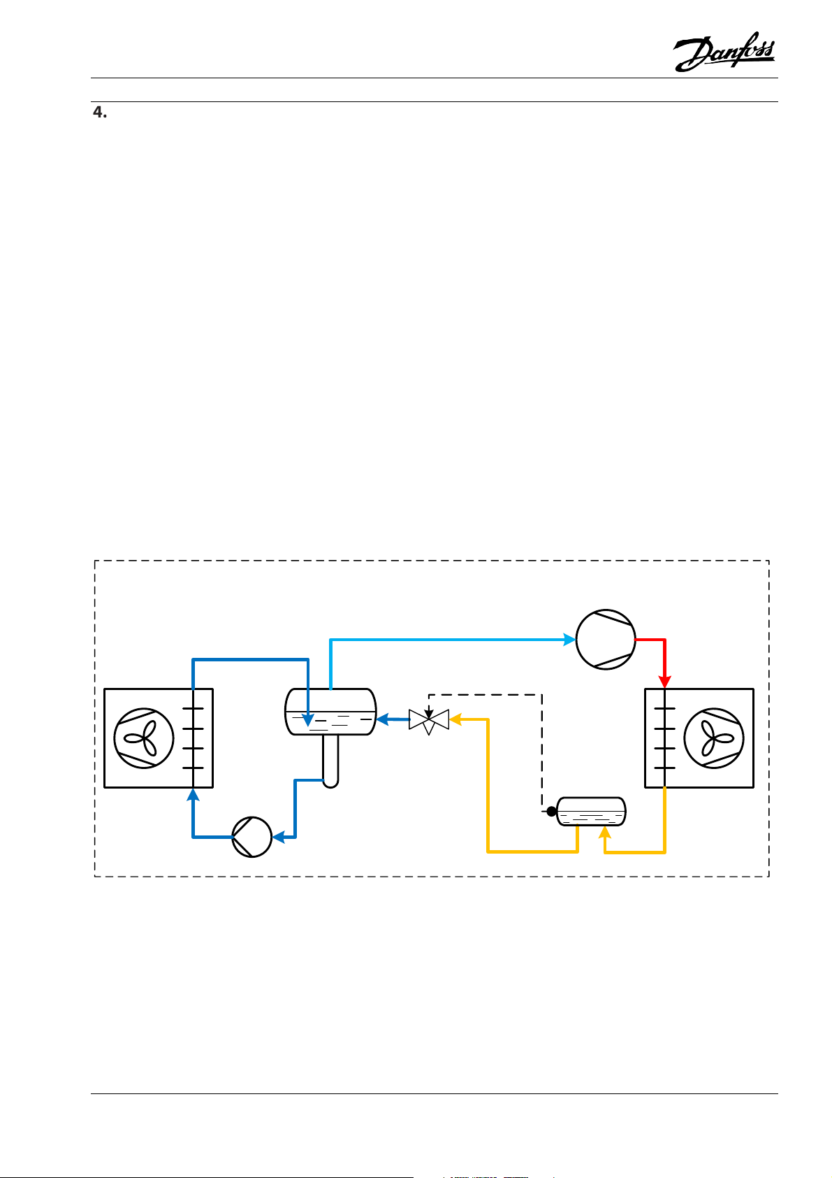
Application Handbook Industrial Refrigeration ammonia and CO2 applications
Liquid level regulation
Liquid level regulation is an important element in the
design of industrial refrigeration systems. It controls
the liquid injection to maintain a constant liquid
level.
Two main different principles may be used when designing a liquid level regulation system:
High-pressure liquid level regulation system (HP LLRS)
Low-pressure liquid level regulation system (LP LLRS)
Both principles can be achieved using mechanical
and electronic components. Float valves offer a simple control, but as the float valve needs to be
mounted in the desired level, a change necessitates
a physical relocation of the valve. Systems employing
a level transmitter are more complex but enable an
easy level change.
High-pressure liquid level regulation systems are typically characterized by:
The sensing device (sensor/float) is placed on the
high-pressure side of the system.
An increase in liquid level will open the expansion de-
vice and pass high-pressure liquid to the low-pressure side of the system, e.g. the regulation attempts
to keep the high-pressure side level constant.
Critical refrigerant charge
Small HP receiver or even no HP receiver
Mainly applied where the HP liquid is distributed to
only one low-pressure application.
Variations in refrigerant volume must be accommo-
dated on the low-pressure side
Figure 4.1: HP liquid level regulation diagram
HP Liquid level control
LP seperator
Evaporator
Compressor
Expansion
valve
HP Receiver
Condenser
© Danfoss A/S (RC-MDP/MWA), 2020-10 AB13778641621700-000702 39
Page 42

Application Handbook Industrial Refrigeration ammonia and CO2 applications
Low-pressure liquid level regulation systems are typically characterized by:
The sensing device (sensor/float) is placed on the low-
pressure side of the system
A decrease in liquid level will open the expansion de-
vice and pass high-pressure liquid to the low-pressure side of the system
Receiver is generally large in size
Figure 4.2: LP liquid level regulation diagram
LP Liquid level control
LP seperator
Evaporator
Expansion
valve
(Fairly) large charge of refrigerant
Mainly applied to decentralized systems where there
can be several low-pressure applications
Variations in refrigerant volume must be accommo-
dated on the high-pressure side
Compressor
HP Receiver
Condenser
In conclusion, HP LLRS are suitable for compact systems like chillers; the advantage is the reduced cost
(small receiver or no receiver). Whereas LP LLRS are
very suitable for decentralised systems with more
than one LP separator and long piping, for instance a
large cold storage; the advantage being the increased safety and reliability.
40 AB13778641621700-000702 © Danfoss A/S (RC-MDP/MWA), 2020-10
Page 43

Application Handbook Industrial Refrigeration ammonia and CO2 applications
4.1 High-pressure liquid level regulation system (HP LLRS)
When designing a HP LLRS, the following points must
be taken into consideration:
As soon as liquid is “formed” in the condenser/condenser outlet, the liquid is fed to the low-pressure
side (the evaporator).
The liquid leaving the condenser will have little or no
sub-cooling. This is important to consider when the
liquid flows to the low-pressure side. If there is pressure loss in the piping or the components, flash-gas
may occur and cause the capacity of the expansion
device to be reduced.
If it is a critical charged system, the refrigerant
charge must be precisely calculated in order to ensure that there is adequate refrigerant in the system.
An overcharge increases the risk of flooding the
evaporator or the liquid separator, causing liquid
carryover into the compressor, as well as liquid hammering. If the system is undercharged, the evaporator will be starved. The size of the low-pressure vessel (liquid separator/evaporator) must be carefully
designed so that it can accommodate the refrigerant
in all conditions without causing liquid carryover.
For the reasons mentioned above, HP LLRS are especially suitable for systems that require a small refrigerant charge, such as chiller units or small freezers.
Liquid chiller units usually do not need receivers,
however, if a receiver is necessary in order to install
a liquid sensing device and/or provide refrigerant to
an oil cooler, the receiver (priority vessel) could be
physically small.
Application Example 4.1.1: Mechanical solution for HP liquid level regulation
From condenser
Pressure equalization line
LLG
To oil cooler
SVA
To separator
SNV
SNV
SVA
EVM
DA NFO S S
PMFH
SVA
SNV
SNV
SVA
Receiver
FIA
SFA
SVA
DSV
Priority for oil
cooler
SVA
SVA
SV1
On large HP LLRS, the SV1 or SV3 float valve is used
as a pilot valve for a PMFH, main valve. As illustrated
above, when the liquid level in the receiver rises
signal to the PMFH main valve to open.The receiver’s function here is to provide a more stable signal for the SV1 float to work with.
above the set level, the SV1 float valve provides a
© Danfoss A/S (RC-MDP/MWA), 2020-10 AB13778641621700-000702 41
Page 44

Application Handbook Industrial Refrigeration ammonia and CO2 applications
Application Example 4.1.2: Electronic solution for HP liquid level regulation
SVA
From condenser
SVA
AKS
4100
Pressure equalization line
SFA
SVA
SNV
DSV
SNV
LLG
SNV
To oil cooler
ICM
To separator
ICFS
SVA
ICAD
ICFS
ICFF
ICF
The system illustrated is an AKS 4100/4100U level
transmitter which sends a level signal to an EKE 347
liquid level controller. The ICM motor valve acts as
an expansion valve.
When designing an electronic LLRS solution, the liquid level signal can be given either by an LLS
4000/AKS 38, which is a level switch (ON/OFF), or an
AKS 4100/4100U, which is a level transmitter (4-20
mA).
The electronic signal is sent to an EKE 347 electronic
controller which controls the injection valve.
Receiver
Priority for oil
cooler
SVA
EKE 347
The liquid injection can be regulated in several dif-
ferent ways:
With a modulating motor valve type ICM with an
ICAD actuator (as shown in the application example
above).
With a pulse-width-modulating expansion valve type
AKVA. The ICFA (in an ICF valve station)/AKVA valve
should be used only where the pulsation from the
valve is acceptable. Line size should be sized to the
full capacity of the ICFA/AKVA valve.
With a regulating valve REG acting as an expansion
valve and an ICS/EVRA solenoid valve to implement
ON/OFF regulation.
42 AB13778641621700-000702 © Danfoss A/S (RC-MDP/MWA), 2020-10
Page 45

Application Handbook Industrial Refrigeration ammonia and CO2 applications
Application Example 4.1.3: Electronic solution for HP liquid level regulation with small/no HP receiver. Same
principle for other evaporative condensers or other condenser types.
From discharge line Cooling water out
Pressure
equalization line
AKS
4100
SVA
EKE 347
Condenser
SNV
In this example, the expansion valve which should be
connected to the liquid level controller, EKE 347, is
not shown.
The system illustrated is an AKS 4100/4100U level
transmitter which sends a level signal to an EKE 347
liquid level controller.
When designing an electronic LLRS solution, the liquid level signal can be given either by an LLS
4000/AKS 38, which is a level switch (ON/OFF), or an
AKS 4100/4100U, which is a level transmitter (4-20
mA).
SVA
SVA
Cooling water in
PHE
To receiver/
expansion device
The electronic signal is sent to an EKE 347 electronic
controller which controls the injection valve.
© Danfoss A/S (RC-MDP/MWA), 2020-10 AB13778641621700-000702 43
Page 46

Application Handbook Industrial Refrigeration ammonia and CO2 applications
Application Example 4.1.4: Mechanical solution for HP liquid level regulation with HFI
From discharge line Cooling water out
Pressure equalization line
SNV
HFI
To separator
The HFI is a direct-acting high-pressure float valve;
therefore, no differential pressure is required to activate the valve.
If the condenser is a plate heat exchanger, the mechanical float valve HFI can be mounted directly on
the heat exchanger header plate.
It may be necessary to connect an equalization line
to either the HP or LP side to remove refrigerant vapour from the float housing, as this may prevent the
Cooling water in
PHE
Condenser
liquid from entering the float housing and thereby
prevent the HFI valve from opening.
During standstill of the plant system, the pressure
will slowly equalize, allowing the entire refrigerant
charge to transfer to the coldest part of the system.
(During wintertime, this can be the condenser).
If pressure equalization is not desired, a solenoid
valve and/or check valve must be fitted.
44 AB13778641621700-000702 © Danfoss A/S (RC-MDP/MWA), 2020-10
Page 47

Application Handbook Industrial Refrigeration ammonia and CO2 applications
If the HFI is not mounted directly on the PHE/condensers:
To enable any liquid condensate to flow to the HFI
by gravity, the HFI must be installed underneath the
condenser.
To ensure trouble-free operation, in most cases a bypass orifice must be installed.
The by-pass orifice connects the gas space in the HFI
housing with the outlet connection of the HFI.
Due to the pressure difference between the highand low-pressure side, the gas is drawn to the lowpressure side, resulting in a slight underpressure in
the housing.
This effect allows gas/vapour to be drawn off.
In addition, this allows the small amount of flash gas
that can form in the liquid feed line or during plant
standstill to be bled away.
Application Example 4.1.5: Installation example for HFI fitted away from condenser with standard HFI housing:
If the HFI is installed close to the condenser and the
pipe design allows vapour/gas to return freely and
easily to the condenser, then the bypass orifice
might not be needed/need to be in operation.
We generally recommend installing/preparing the
bypass orifice.
Guidelines for size of by-pass orifice:
By-pass orifice
(washer with hole) in
this line
SNV
SNV
SVA
To LP separator
HP liquid from
condenser
HFI
SVA
REG
For manual operation/
expansion
© Danfoss A/S (RC-MDP/MWA), 2020-10 AB13778641621700-000702 45
Page 48

Application Handbook Industrial Refrigeration ammonia and CO2 applications
Application Example 4.1.6: Installation example for HFI fitted away from condenser with HFI housing with
two extra connections:
SNV
HP liquid from
By-pass orifice
condenser
(washer with hole) in
this line
SNV
HFI
SVA
For drain of
liquid in float
SVA
REG
SNV
To LP separator
For manual operation/
expansion
46 AB13778641621700-000702 © Danfoss A/S (RC-MDP/MWA), 2020-10
Page 49

Application Handbook Industrial Refrigeration ammonia and CO2 applications
4.2 Low-pressure liquid level regulation system (LP LLRS)
When designing an LP LLRS, the following points
must be taken into consideration:
The liquid level in the low-pressure vessel (liquid
separator/ shell-tube evaporator) is maintained at a
constant level. This is safe for the system, since an
The HP receiver must be large enough to accumulate
the liquid refrigerant coming from the evaporators.
When the content of refrigerant in some evaporators varies with the cooling load, some evaporators
are shut off for service, or part of the evaporators
are drained for defrosting.
excessively high liquid level in the liquid separator
may cause liquid carryover to the compressor, and
an excessively low level may lead to cavitation of the
refrigerant pumps in a pump circulation system.
Often, LLS 4000/AKS 38s are employed as high- and
low-level alarms, although when a level transmitter
As a result of the above, LP LLRS are especially suitable for decentralised systems in which there are
many evaporators, and there is a large refrigerant
charge, e.g. cold stores. With LP LLRS, these systems
can run safely even though it is impossible to precisely calculate the refrigerant charge.
is used, the low-level alarm is usually taken from the
level transmitter.
Application Example 4.2.1: Mechanical solution for LP liquid level regulation
SVA
SVA
Suction line
SVA
SVA
SV4
Wet return line
LLG
SVA
SNV
SNV
Liquid
separator
SFA
LLS 4000/
AKS 38
DSV
AKS 38
ICS
EVM
SNV
FIA
SVA
From
receiverLLS 4000/
SNV
SVA
SVA
Liquid feed line/
pump suction
line
SV float valves “monitor” the liquid level in low-pressure vessels.
If the system capacity is small, the SV4, valves can
act directly as an expansion valve in the low-pressure vessel as shown.
SVA
© Danfoss A/S (RC-MDP/MWA), 2020-10 AB13778641621700-000702 47
Page 50

Application Handbook Industrial Refrigeration ammonia and CO2 applications
Application Example 4.2.2: Mechanical solution for LP liquid level regulation
SVA
SNV
SFA
Wet return line
DSV
SNV
LLS 4000/
AKS 38
LLS 4000/
AKS 38
LLG
Liquid
separator
SNV
SVA
Liquid feed line/
pump suction
line
If the system capacity is large, the float valve SV4 is
used as a pilot valve for the PMFL main valve.
SVA
SVA
SVA
Suction line
SVA
EVM
DANFOSS
PMFL
SNV
FIA
SVA
SV4
SVA
SVA
As illustrated above, when the liquid level in the liq-
uid separator falls below the set level, the float valve
SV4 provides a signal to the PMFL value to open.
From
receiver
48 AB13778641621700-000702 © Danfoss A/S (RC-MDP/MWA), 2020-10
Page 51

Application Handbook Industrial Refrigeration ammonia and CO2 applications
Application Example 4.2.3: Electronic solution for LP liquid level regulation
Wet return line
SVA
SNV
LLG
SNV
Liquid feed line/
pump suction
line
SNV
Liquid
separator
SVA
SFA
DSV
LLS 4000/
AKS 38
SVA
SVA
AKS
4100
SVA
Suction line
EKE 347
ICM
ICFS
ICFE
ICFO
ICF
ICFS
From
receiver
ICFF
The level transmitter AKS 4100/4100U monitors the
liquid level in the separator and sends a level signal
to the liquid level controller EKE 347, which sends a
modulating signal to the ICAD actuator of the motor
valve ICM on the ICF valve station. The ICM motor
valve acts as an expansion valve.
The solenoid valve ICFE on the ICF valve station is
being used as an additional solenoid valve to ensure
100% closure during “off” cycles.
The liquid level controller EKE 347 also provides relay outputs for upper and lower limits and for alarm
levels. However, it is recommended that a level
switch LLS4000/AKS38 is fitted as a mechanical highlevel alarm.
© Danfoss A/S (RC-MDP/MWA), 2020-10 AB13778641621700-000702 49
Page 52

Application Handbook Industrial Refrigeration ammonia and CO2 applications
Application Example 4.2.4: Electronic solution for LP liquid level regulation
Wet return line
SVA
SNV
LLG
SNV
Liquid feed line/
pump suction
line
SNV
Liquid
separator
SVA
SFA
DSV
LLS 4000/
AKS 38
SVA
SVA
AKS
4100
SVA
Suction line
ICFA
EKE 347
ICFS
ICFE
ICFO
ICF
ICFS
From
receiver
ICFF
This solution is similar to the solution shown in Application Example 4.2.3. However, with this example
the motor valve ICM is replaced by a pulse-width
electronically operated expansion valve ICFA on the
ICF valve station. The solenoid valve ICFE, which is
also mounted on the ICF valve station, is being used
as an additional solenoid valve to ensure 100% closure during “off” cycles.
The line should be sized to the full capacity of the
ICFA valve, or AKVA valve if serially connected.
The liquid level controller EKE 347 also provides re-
lay outputs for upper and lower limits and for alarm
level. However, it is recommended that a level
switch LLS4000/AKS38 be fitted as a mechanical
high-level alarm.
50 AB13778641621700-000702 © Danfoss A/S (RC-MDP/MWA), 2020-10
Page 53

Application Handbook Industrial Refrigeration ammonia and CO2 applications
Application Example 4.2.5: Electronic solution for LP liquid level regulation
Wet return line
SVA
SNV
LLG
SNV
Liquid feed line/
pump suction
line
SNV
Liquid
separator
SVA
SFA
LLS 4000/
AKS 38
DSV
LLS 4000/
AKS 38
SVA
SVA
SVA
Suction line
LLS 4000/
AKS 38
ICFR
ICFS
ICFE
ICFO
ICFS
From
receiver
ICFF
ICF
This solution controls the liquid injection using
on/off regulation. The level switch LLS 4000/AKS 38
on the right side of the level sensor controls the
switching of the solenoid valve ICFE in accordance
with the liquid level in the separator. The hand regulating valve ICFR acts as the expansion valve.
© Danfoss A/S (RC-MDP/MWA), 2020-10 AB13778641621700-000702 51
Page 54

Application Handbook Industrial Refrigeration ammonia and CO2 applications
4.3 Summary
Solution Application Benefit Limitations
High-pressure liquid level regulation system (HP LLRS)– see section 4.1
High-pressure mechanical
solution: SV1/3 + PMFH
Receiver
Applicable, especially to
critical charged systems.
Purely mechanical. Wide
capacity range.
High-pressure electronic
solution: AKS 4100 + EKE
347 +ICM
High-pressure mechanical
solution: HFI
LT
Receiver
M
PHE
condenser
Applicable, especially to
critical charged systems.
LC
Applicable, especially to
critical charged systems.
Flexible and compact.
Possible to monitor and
control remotely. Covers
wide range of capacity.
Purely mechanical.
Simple solution.
Especially suitable for
plate heat exchangers.
Low-pressure liquid level regulation system (LP LLRS)– see section 4.2
Low-pressure mechanical
solution: SV4-6
Low-pressure mechanical
solution: SV4-6+PMFL
Low-pressure electronic
solution: AKS 4100 + EKE
347 +ICM
Low-pressure electronic
solution: AKS 4100 + EKE
347 +AKVA
Low-pressure solution:
LLS 4000/AKS 38
+ICFE+ICFR
Liquid
separator
Liquid
separator
Liquid
separator
Liquid
separator
Liquid
separator
LC
M
LT
LC
AKVA
LT
LC
Applicable to small
systems
Particularly applicable to
decentral systems like
cold storages.
Particularly applicable to
decentral systems like
cold storages.
Particularly applicable to
decentral systems like
cold storages.
Particularly applicable to
decentral systems like
cold storages.
Purely mechanical.
Simple, low cost solution.
Purely mechanical. Wide
capacity range.
Flexible and compact.
Possible to monitor and
control remotely. Covers
wide range of capacity.
Flexible and compact.
Possible to monitor and
control remotely.
Covers a wide range of
capacities. Easy to install.
Simple.
Inexpensive.
Unable to control
remotely. The distance
between SV and PMFH is
limited to several metres.
A bit slow in response.
Complicated to change
setpoint if not correct.
Not permitted for
flammable refrigerants.
Limited capacity.
Complicated to change
setpoint if not correct.
Unable to control
remotely, the distance
between SV and PMFL is
limited to several metres.
A little bit slow in
response.
Complicated to change
setpoint if not correct.
Not permitted for
flammable refrigerants.
Not permitted for
flammable refrigerants.
Just 40 mm for level
adjustment.
Very dependent on the
adjustment of the REG
valve. Not suitable for
systems with big capacity
fluctuations.
Complicated to change
setpoint if not correct.
52 AB13778641621700-000702 © Danfoss A/S (RC-MDP/MWA), 2020-10
Page 55

Application Handbook Industrial Refrigeration ammonia and CO2 applications
Evaporator controls
Oil Cooler
Compressor
Evaporator
Expansion valve
The evaporator is the part of the refrigeration system where the effective heat is transferred from the
media you want to cool down (e.g. air, brine, or the
product directly) to the refrigerant.
Oil Separator
Condenser
Liquid supply controls (Section 5.2): Describes methods for controlling liquid injection for a direct expansion (DX) evaporator and liquid supply for a pumped
circulation evaporator.
Therefore, the primary function of an evaporator
control system is to achieve the desired media temperature. Furthermore, the control system should
also keep the evaporator operating efficiently and
trouble-free at all times.
Specifically, the following control methods may be
necessary for evaporators:
Temperature controls (Section 5.1): Describes methods for controlling media temperature within tight
thresholds with high accuracy, as well as for operating evaporators at different temperature levels.
Defrost Methods (Section 5.6): Briefly describes the
different methods for defrosting evaporators.
Hot Gas Defrosting Controls (Section 5.6.3): Describes the steps of the hot gas defrost sequence
and general considerations. Hot gas defrosting application examples are covered separately for DX evaporators and pumped circulation evaporators, since
they differ, for example, in the draining methods.
© Danfoss A/S (RC-MDP/MWA), 2020-10 AB13778641621700-000702 53
Page 56

Not all valves are shown.
Application Handbook Industrial Refrigeration ammonia and CO2 applications
5.1 Temperature controls
5.1.1 Media temperature control
Solutions are provided for where there are stringent
requirements for accurate temperature control in
connection with refrigeration, for example:
Cold room for fruits and food products
Work premises in the food industry
Process cooling of liquids
Application Example 5.1.1: Media temperature control using either pilot-operated valve or motor-operated
valve
ICAD
CVP
Option 1
CVE
SVA
To liquid separator
Option 2
ICAD
ICMICS
ICFE
ICFF
REG
ICFS
EVRA
ICF solution
Serial solution
FIA
ICFR
Evaporator
ICFO
ICFS
SVA
Application Example 5.1.1 shows a solution for accurate media temperature control. Furthermore, there
is a need to protect the evaporator against an excessively low pressure to prevent the products from
freezing up in the application.
This design can be applied for DX or pumped liquid
circulation evaporators with any type of defrost system.
From liquid separator
SVA
The servo valve (ICS) is controlled by the two serially
connected pilot valves (CVE) in the S2 port, con-
trolled by a media temperature controller, e.g.
Danfoss EKC 361, and CVP in the S1 port.
The CVP is adjusted according to the lowest pressure
permitted for the application.
The functionality of the pilot-operated servo valve
solution (ICS) is described on the next page.
Not to be used for construction purposes
54 AB13778641621700-000702 © Danfoss A/S (RC-MDP/MWA), 2020-10
Page 57

Application Handbook Industrial Refrigeration ammonia and CO2 applications
The media temperature controller will control the
temperature in the application at the desired level
by controlling the opening of the CVE pilot valve, and
thereby controlling the evaporating pressure to
match the required cooling load and temperature.
The second control option is the motor valve ICM,
where a media temperature controller controls the
opening degree of the ICM motor valve.
This solution will control the temperature with an
accuracy of +/- 0.25°C. If the temperature falls below
this range, the EKC controller can close the solenoid
valve in the liquid line.
The media temperature controller EKC 361 will control all functions of the evaporator, including thermostat and alarms.
For more details, please refer to the manual of the
EKC 361 controller.
© Danfoss A/S (RC-MDP/MWA), 2020-10 AB13778641621700-000702 55
Page 58

Application Handbook Industrial Refrigeration ammonia and CO2 applications
5.1.2 Multi-temperature changeover
In the process industry, it is very common to use an
evaporator for different temperature settings.
When the operation of an evaporator is required at
two different fixed evaporating pressures, this can
be achieved by using one servo valve ICS with two
constant pressure pilots.
Application Example 5.1.2: Evaporator pressure control - changeover between two pressure levels
P: CVP
Evaporator
S1: EVM
ICFR
ICFS
ICS
SVA
S2: CVP
ICFE
ICFO
ICFF
REG
ICFS
EVRA
To liquid separator
SVA
ICF solution
From liquid separator
Serial solution
SVA
FIA
Application Example 5.1.2 shows a solution for controlling two evaporating pressures in evaporators.
This solution can be used for DX or pumped liquid
circulation evaporators with any type of defrost system.
CVP pilot in the S2 port. When the solenoid is de-en-
ergized, the evaporator pressure will follow the set-
ting of the CVP pilot in the P port.
The Danfoss ICS pilot-operated servo valve solution
has options for being controlled by either 1 pilot or 3
The servo valve ICS is equipped with one EVM (NC)
solenoid valve pilot in the S1 (serial 1) port and two
CVP constant pressure pilots in ports S2 and P respectively.
pilots. The 1-pilot system works by having a pilot
valve to the opening of the servo valve based on the
pilot’s set conditions. The 3-pilot system has two
lines of pilots, one line with 1 pilot (the parallel line)
and another line with 2 pilots serially connected (S1
The CVP in the S2 (serial 2) port is adjusted to the
lower operating pressure and the CVP in the P port is
adjusted to the higher operating pressure.
When the solenoid in the S1 port is energized, the
and S2 ports). Having 2 pilots serially connected al-
lows more options to be set for the operation of the
servo valve. The pilot in the parallel line (P port) can
open the servo valve independently of the pilots in
evaporator pressure will follow the setting of the
56 AB13778641621700-000702 © Danfoss A/S (RC-MDP/MWA), 2020-10
Page 59

I II
Outlet air tempera-
+3°C
+8°C
Evaporating tem-
–
2°C +2°C
Temperature
5K 6K
Refrigerant
R 717
R 717
Evaporating pres-
3.0 bar
3.6 bar
Application Handbook Industrial Refrigeration ammonia and CO2 applications
the serial ports, which is shown in the example below.
P port P port
ICS ICS
1 pilot 3 pilots
Example:
ture
perature
change
S1 S2
Serial
Parallel
sure
S2: CVP is preset to 3.0 bar, and
P: CVP is preset to 3.6 bar.
I: EVM pilot opens. The evaporating pressure is
therefore controlled by S2: CVP.
II: EVM pilot closes. The evaporating pressure is
therefore controlled by P: CVP.
© Danfoss A/S (RC-MDP/MWA), 2020-10 AB13778641621700-000702 57
Page 60

Application Handbook Industrial Refrigeration ammonia and CO2 applications
5.2 Liquid supply control
Liquid supply to the evaporator is controlled differently depending on the system complexity, refrigerant and application.
There are 3 different liquid supplies to the evaporator: Direct expansion (DX), pump circulation and natural circulation.
For direct expansion, high-pressure liquid refrigerant
is supplied to the evaporator through an expansion
valve. In the evaporator it is fully evaporated and superheated to avoid liquid hammering in the compressor. The liquid supply is controlled by a superheat-controlled expansion valve.
For pump circulation, a liquid refrigerant is pumped
to the evaporator from a separator vessel. The refrigerant is partially evaporated in the evaporator
and returned to the separator, where the vapour is
fed to the compressor.
For natural circulation, a liquid refrigerant is driven
by gravity to the evaporator. Since the refrigerant
flow is driven by gravity, and not a pump, special
consideration must be given to the distance from
separator to evaporator and the height of risers in
the return lines. The refrigerant is partially evapo-
rated, like for the pump-circulated system, and re-
turned to the separator. Controls for natural circula-
tion are similar to those for a pump-circulated sys-
tem, therefore they are covered in the section with
pump-circulated controls.
58 AB13778641621700-000702 © Danfoss A/S (RC-MDP/MWA), 2020-10
Page 61

Application Handbook Industrial Refrigeration ammonia and CO2 applications
5.2.1 Direct expansion control
When designing liquid supply for direct expansion
evaporators, the following requirements should be
met:
The liquid injection is controlled by a superheat-controlled expansion valve, which maintains the superheat at the outlet of the evaporator within a desired
range. This expansion valve can be either a thermo-
The liquid refrigerant supplied to the evaporator is
completely evaporated. This is necessary to protect
static expansion valve, or an electronic expansion
valve.
the compressor against liquid hammer.
The media “off” temperature from the evaporator is
maintained within the desired range.
The temperature control is normally achieved by
ON/OFF control, which starts and stops the liquid
supply to the evaporator based on the media temperature.
Application Example 5.2.1: Direct expansion (DX) evaporator with thermostatic expansion
SVA
To suction line
Evaporator
SVA
Application Example 5.2.1 shows a typical installation for a DX evaporator without hot gas defrosting.
The liquid injection is controlled by the thermostatic
expansion valve, TEA, which maintains the refrigerant superheat at the outlet of the evaporator at a
constant level. TEA is designed for ammonia.
Danfoss also supply thermostatic expansion valves
for fluorinated refrigerants. For CO2 DX systems,
electronic expansion valves should be used, such as
an ICM motor valve.
The media temperature should be controlled by a
digital thermostat (Danfoss EKC 202), which will control the on/off switching of the solenoid valve, EVRA,
according to the temperature signals from the temperature sensors. Danfoss can provide digital thermostats and temperature sensors.
TEA
From receiver
SVA
EVRA
This solution can also be applied to DX evaporators
with natural or electric defrost.
Natural defrost is only possible if the cold room temperature is well above 0°C. It is achieved by stopping
the refrigerant flow to the evaporator, and keeping
the fans running. Electric defrost is achieved by stopping the fans and the refrigerant flow to the evaporator, and at the same time switching on an electric
heater inside the evaporator fin block.
FIA
© Danfoss A/S (RC-MDP/MWA), 2020-10 AB13778641621700-000702 59
Page 62

Not all valves are shown.
Application Handbook Industrial Refrigeration ammonia and CO2 applications
Not to be used for construction purposes
60 AB13778641621700-000702 © Danfoss A/S (RC-MDP/MWA), 2020-10
Page 63

Application Handbook Industrial Refrigeration ammonia and CO2 applications
Application Example 5.2.2: Direct expansion (DX) evaporator with electronic expansion by a motor valve
(ICM)
To suction line
SVA
Evaporator
ICM
ICFS
SVA
ICFE
ICFO
ICFS
ICFF
ICAD
ICM
EVRA
ICF solution
Serial solution
FIA
SVA
From receiver
Application Example 5.2.2 shows a typical installation for an electronically controlled DX evaporator
without hot gas defrost.
The ICF control solution is shown in the liquid supply
line, but the serial solution could be used instead.
The ICF will accommodate up to six different modules assembled in the same housing, offering a compact and easy-to-install control solution.
The liquid injection is controlled by the motor valve,
ICM, which is controlled by an evaporator controller,
e.g. EKC 315A (not shown). The evaporator controller will measure the superheat by means of a pressure transmitter and a temperature sensor on the
outlet of the evaporator. The evaporator controller
controls the opening degree of the ICM motor valve
© Danfoss A/S (RC-MDP/MWA), 2020-10 AB13778641621700-000702 61
in order to maintain the superheat at the optimum
level.
At the same time, the evaporator controller operates as a digital thermostat which controls the
on/off switching of the solenoid valve, ICFE/EVRA,
depending on the media temperature signal from a
temperature sensor on the evaporator.
Compared with the solution in Application Example
5.2.1, this solution will constantly adapt the opening
degree of the injection valve to ensure maximum capacity and efficiency. Furthermore, this solution offers more accurate control of media temperature.
This solution can also be applied to DX evaporators
with natural or electric defrost.
Page 64

Application Handbook Industrial Refrigeration ammonia and CO2 applications
Application Example 5.2.3: Direct expansion (DX) evaporator with electronic expansion by a PWM AKVA valve
To suction line
SVA
ICFS
ICFA
Evaporator
ICFF
ICFS
SVA
AKVA
Application Example 5.2.3 shows an installation for
an electronically controlled DX evaporator without
hot gas defrost.
This application example shows an ICF control solution for an electronically controlled DX evaporator
without hot gas defrost.
The ICF control solution is shown in the liquid supply
line, but the serial solution could be used instead.
The ICF can accommodate up to six different models
in the same housing, offering a compact and easy-toinstall control solution.
The liquid injection is controlled by the pulse width
modulation (PWM) electronic expansion valve, ICFA,
which is controlled by an evaporator controller, e.g.
ICF solution
From receiver
Serial solution
FIA
EKC 315A (not shown). The evaporator controller will
measure the superheat by means of a pressure
transmitter and a temperature sensor on the outlet
of the evaporator. The evaporator controller con-
trols the opening degree of the ICFA valve in order to
maintain the superheat at the optimum level.
Compared with the solution in Application Example
5.2.1, this solution will constantly adapt the opening
degree of the injection valve to ensure maximum ca-
pacity and efficiency. Furthermore, this solution of-
fers more accurate control of media temperature.
This solution can also be applied to DX evaporators
with natural or electric defrost.
SVA
62 AB13778641621700-000702 © Danfoss A/S (RC-MDP/MWA), 2020-10
Page 65

Application Handbook Industrial Refrigeration ammonia and CO2 applications
5.2.2 Flooded evaporator circulation control
Traditional industrial refrigeration systems are
flooded systems. In a flooded system, the evaporators are injected with more liquid than is needed for
full evaporation, which means that the refrigerant is
not superheated in the evaporator. A separator vessel is used for supplying liquid refrigerant to the
evaporator, to collect the wet return flow and sepa-
Circulation rate
The amount of liquid supplied to the evaporators is
defined by the "circulation rate". The circulation rate
is 1 when exactly enough liquid is supplied to be fully
evaporated in the cooler. If, however, twice as much
liquid is injected, the circulation rate is 2. See Table
5.1 below.
rate the phases of the refrigerant. From the separator, the gas phase of the refrigerant is fed to the
compressor suction line and the liquid phase is fed
to the evaporator supply line.
For flooded evaporators, the heat exchanger area is
not used for superheating the refrigerant. In terms
of heat transfer, superheating refrigerant is inefficient compared to evaporation, due to a lower heat
transfer for superheating compared to evaporation.
Therefore, a flooded evaporator can be operated at
a higher evaporation temperature than if it was running as DX with superheat. A detailed explanation of
heat transfer principles for evaporators can be found
in chapter 12.
The benefit of liquid overfeed is increased efficiency
of the coolers, due to better utilization of evaporator
surface area, and better heat transfer, due to a
higher heat transfer coefficient. In addition, flooded
systems are relatively easy to control.
Table 5.1: Examples of refrigerant phases’ fractions at different circulation rates
Circulation rate, n Liquid mass flow sup-
plied
1 100% 100% 0%
2 100% 50% 50%
4 100% 25% 75%
8 100% 12.5% 87.5%
Gas mass flow out Liquid mass flow out
Natural circulation flooded evaporators
For natural circulation flooded evaporators, the refrigerant flow is driven by gravity. It is essential to
the refrigerant flow that pressure losses are kept as
low as possible, thus fewer flow controlling components are typically installed in the supply and return
The refrigerant flow is less controllable compared to
a pumped circulation flooded evaporator and a natural circulation evaporator is placed closer to the liquid separator since it is mainly used as a plate heat
exchanger for water or glycol chillers.
lines.
Pumped circulation flooded evaporators
When compared to ammonia DX systems, ammonia
pump circulation systems control becomes simpler
© Danfoss A/S (RC-MDP/MWA), 2020-10 AB13778641621700-000702 63
Page 66

Application Handbook Industrial Refrigeration ammonia and CO2 applications
as a well-dimensioned pump separator protects
compressors against hydraulic shock. The pump separator ensures that only “dry” refrigerant vapour is
returned to the compressors. The evaporation control is also simplified as only a basic on/off liquid
control to the evaporators is required.
The injected liquid at the correct temperature is
pumped from a separator to the evaporators. When
liquid is needed, a solenoid valve in front of the
evaporator is opened. A manual regulating valve is
usually fitted after the solenoid valve to allow the required circulation rate to be set and hydraulic balance to be achieved in the system.
Temperature control in evaporators can be managed
as follows:
Regulating valve for distribution control + ON/OFF so-
lenoid valve for temperature control
Regulating valve for distribution control + pulse-width
modulated solenoid valve for temperature control
AKV valves for both distribution control (orifice size)
and PWM temperature control.
64 AB13778641621700-000702 © Danfoss A/S (RC-MDP/MWA), 2020-10
Page 67

Application Handbook Industrial Refrigeration ammonia and CO2 applications
Figure 5.2.1: Liquid injection valves for pumped circulated systems
To separator
SVA
AKVA
Option 1
From separator
SVA
Option 2
5.3 Injection with a solenoid valve (EVRA)
In a traditional flooded system, liquid injection is
controlled by a thermostat which constantly
measures the air temperature.
The solenoid valve is opened for several minutes or
longer until the air temperature has reached the setpoint. During injection, the mass of the refrigerant
flow is constant.
This is a very simple way to control the air temperature. However, the temperature fluctuation caused
by the differential of the thermostat may cause unwanted side effects in some applications, e.g. dehumidification and inaccurate control.
SVAREG
EVRA
FIA
5.4 Injection with a pulse width modulation
AKV(A)
valve
Instead of injecting periodically, as described above,
one can also constantly adapt the liquid injection to
the actual demand. This can be done by means of a
pulse-width-modulated (PWM) AKV(A) valve type
controlled by an AK-CC 450.
The air temperature is constantly measured and
compared to the reference temperature. When the
air temperature reaches the setpoint, the opening of
the AKV(S) is reduced, giving it a smaller opening angle during a cycle, resulting in less capacity and vice
versa. The duration of a cycle is adjustable between
30 sec. and 900 sec.
In principle, the regulation in this system is performed with a PI function. This results in reduced
fluctuation of the regulated air temperature with
stable loads, giving a more constant air humidity.
The function offers constant temperature regulation
with a temperature value that lies half way between
the on and off values of the thermostat.
The operating parameters of the PI regulation are
automatically optimized via the preset on and off
values and the degree of opening of the valve. The
© Danfoss A/S (RC-MDP/MWA), 2020-10 AB13778641621700-000702 65
Page 68

Application Handbook Industrial Refrigeration ammonia and CO2 applications
differential affects the amplification of the regulator
and can therefore not be set to less than 2K to ensure regulation stability. In a flooded system, this
means that the average refrigerant flow is constantly
controlled and adapted to the demand, with the circulation rate decreasing when less refrigerant is injected.
This approach to liquid injection in a flooded system
is very versatile. The amount of injected liquid can
be precisely controlled.
A direct effect of this is a lower average surface tem-
perature of the air cooler, resulting in a smaller ΔT
between the refrigerant and the air. This increases
the accuracy and the energy efficiency of the system.
66 AB13778641621700-000702 © Danfoss A/S (RC-MDP/MWA), 2020-10
Page 69

Not all valves are shown.
Application Handbook Industrial Refrigeration ammonia and CO2 applications
Application Example 5.4.1: Pumped liquid circulation evaporator with solenoid valve for liquid injection
To liquid separator
SVA
ICFR
ICFS
ICFE
Evaporator
ICFF
ICFO
ICFS
SVA
REG
Application Example 5.4.1 shows a typical installation for a pumped liquid circulation evaporator without hot gas defrost and can also be applied to
pumped liquid circulation evaporators with natural
or electric defrost.
The media temperature is maintained at the desired
level by a digital thermostat, e.g. EKC 202, which
controls the on/off switching of the solenoid valve,
EVRA, according to a media temperature signal from
a temperature sensor, e.g. AKS 21.
ICF solution
From liquid separator
Serial solution
SVA
EVRA
FIA
The amount of liquid injected into the evaporator is
controlled by the opening of the manual regulating
valve, ICFR/REG. It is important to set this regulating
valve at the right opening degree. Too high an opening degree will lead to frequent operation of the solenoid valve with resultant wear. Too low an opening
degree will starve the evaporator of liquid refrigerant.
Not to be used for construction purposes
© Danfoss A/S (RC-MDP/MWA), 2020-10 AB13778641621700-000702 67
Page 70

Not all valves are shown.
Application Handbook Industrial Refrigeration ammonia and CO2 applications
Application Example 5.4.2: Pumped liquid circulation evaporator with pulsed width modulated (PWM) AKV
valve for liquid injection
To liquid separator
SVA
ICFS
Evaporator
ICFA
ICFF
ICFS
SVA
AKVA
Instead of injecting periodically, as described above,
one can also constantly adapt the liquid injection to
the actual demand. This can be done with a PWM
AKVA valve or an ICF with an ICFA solenoid module.
The air temperature is constantly measured and
compared to the reference temperature with a digital thermostat, e.g. AK-CC 450. When the air temperature reaches the setpoint, the AKVA valve opening
is reduced. This decreases the degree of opening
during the cycle, resulting in less capacity. The duration of a cycle is adjustable between 30 sec. and 900
sec.
ICF solution
From liquid separator
Serial solution
FIA
SVA
In a flooded system, this means that the average refrigerant flow is constantly controlled and adapted
to demand.
This approach to liquid injection in a flooded system
is very versatile. The amount of injected liquid can
be precisely controlled, which increases the accuracy
and the energy efficiency of the system.
Two-phase flow – a flow that is a mixture of vapour
and liquid – presents some special problems with regard to the design of piping. Two-phase flow is usu-
Not to be used for construction purposes
68 AB13778641621700-000702 © Danfoss A/S (RC-MDP/MWA), 2020-10
5.5 Risers
from flooded evaporators, which are evaporators
where more refrigerant is circulated than is evaporated. The amount evaporated is proportional to the
ally in the return line
Page 71

Application Handbook Industrial Refrigeration ammonia and CO2 applications
capacity of the heat exchanger and usually the situation is described with a capacity and a ‘circulation
rate’.
There are two key considerations for two-phase
lines:
The pressure loss: The pressure loss of a two-phase
flow is much higher than a single phase (vapour)
flow at the same speed, so the speed in two-phase
lines is usually kept lower than in vapour-only lines.
For low temperature applications, pressure loss presents a large performance penalty, while for thermosyphon (self-circulation) systems, the pressure
loss must be small to ensure proper circulation.
Figure 5.5.1: Two-phase flow patterns in horizontal
pipe
The flow pattern: The flow pattern describes how
the two phases flow, mixed or separately. Depending on the composition (% of each phase) and overall
speed, the combined flow behaves very differently,
and the pressure loss is a result of the combined behaviour.
The topic of flow pattern is very complex, so only a
simple explanation will be given here. Looking at the
sketched flow patterns in horizontal pipes in Figure
5.5.1 below, it can generally be seen that from top
to bottom and left to right there is an increasing
amount of vapour and with that a higher overall velocity.
Note how a higher vapour speed disturbs the liquid
through friction on the surface, inducing waves that
eventually reach the top of the pipe to enclose gas
‘slugs’. Eventually the speed becomes so high that
the friction forces are stronger than the gravitational
forces, and the ‘annular’ flow pattern is reached. In
the annular flow, the liquid flows in a ‘film’ on the inner surface of the pipe with the high-speed vapour
flowing in the centre of the pipe.
In a horizontal pipe, any of these flow patterns are
usually not a problem, provided the pressure loss is
accounted for. It is common practice to install twophase ‘horizontal’ lines with a small downward slope
towards the destination to ensure that the liquid is
safely transported to the destination.
In a vertical pipe, however, it is very different. Downward flow presents its own problems, mainly relating
to liquid falling and possibly inducing pressure fluctuations, but transport of the liquid to the destination is almost guaranteed. With upward flow, however, the liquid transport is not guaranteed and that
can give rise to problems in refrigeration systems.
In Figure 5.5.2 below, a different flow pattern in upwards flow is shown. The vapour speed generally increases from left to right. With very low velocity, the
pipe fills with liquid and the vapour bubbles through
it. Increased velocity collects the vapour in larger
‘slugs’ that, with a further increase, start to fill the
centre of the pipe. Once the slugs collect to form a
channel in the middle, the flow is said to be annular.
The remarkable thing about annular flow is that the
friction forces on the vapour/liquid surface can drag
the liquid on the pipe wall upwards, thereby providing an upward liquid transport.
© Danfoss A/S (RC-MDP/MWA), 2020-10 AB13778641621700-000702 69
Page 72

Application Handbook Industrial Refrigeration ammonia and CO2 applications
Figure 5.5.2: Two-phase flow patterns in vertical
pipe
Since the amount of vapour is determined by the
evaporating capacity, it is not usually an option to increase vapour flow. However, the same vapour flow
can yield higher velocities in a smaller pipe and thus
the Figure 5.5.2 above can be seen as the same vapour flow with pipe size decreasing left to right.
m/s2 = 0.19 bar. The pressure loss is most likely
somewhat lower since, because of the vapour bubbles, the average density is lower than saturated liquid, though not much lower.
Reducing the pipe size increases the speed. Below in
Figure 5.5.3 is a Coolselector2 calculation of a 3m
Most technicians would intuitively think that a
higher velocity means greater pressure loss, but that
is not the case with vertical upward two-phase flow.
DN50 pipe with 100kW evaporator capacity at -10°C
R717, circulation rate 3. It is remarkable that the
speed is relatively high at 14 m/s, but the pressure
loss is only 0.022 bar. The explanation is that the
In the ‘bubbly’ flow pattern, the liquid fills up most
of the pipe from top to bottom before it starts to
overflow the top. Thus, the pressure loss associated
with this flow is the height of the pipe, multiplied by
the liquid density and the gravitational constant. In
an example with R717 at -10°C in a large pipe with a
height of 3 meters, this is 652 kg/m3 * 3 m * 9.81
pressure loss relates to (almost) pure gas running in
a slightly smaller ‘pipe’ (the channel in the centre of
the pipe) and the friction of this pulls up the liquid.
The gravitational pressure loss is no longer the major
part of the pressure loss, but rather the frictional
pressure loss dominates.
Figure 5.5.3: Pressure loss in riser at appropriate circulation rate
70 AB13778641621700-000702 © Danfoss A/S (RC-MDP/MWA), 2020-10
Page 73

Application Handbook Industrial Refrigeration ammonia and CO2 applications
The above 100kW at -10°C R717, circulation rate 3,
equates to 833.9 kg/hr. Using the same flow but
with a much larger circulation rate simulates a very
low capacity and thus a low vapour flow as shown in
Figure 5.5.4. The speed is now 0.48 m/s – 1/28th
that of before – but the pressure loss is now 0.14 bar
– approximately 6 times higher. This is due to the
pipe filling up with liquid.
Figure 5.5.4: Pressure loss in riser at too high circulation rate
An excessively high pressure loss has, as mentioned
above, some serious penalties. In low temperature
applications, a pressure loss of 0.15 bar could have a
significant impact on the efficiency and capacity of
the system. For thermosyphon systems, the combined pressure loss in the return pipe and the heat
exchanger must be smaller than the driving pressure
provided by the liquid column in the inlet of the
evaporator. Similar to the pressure loss calculation
above, the driving pressure is the product of liquid
density, height and gravitation. The vertical part of
the return pipe is, more or less, the same as the vertical pipe providing the driving height, so a liquidfilled return pipe provides a pressure loss that is
more or less the same as the driving pressure – leaving very little pressure drop available for the evaporator. In effect, that means that there will be no circulation in the system, the evaporator performance
will drop and it will not deliver what is expected of it.
The return pipe therefore needs to be designed
carefully to avoid too great a pressure drop. The top
Coolselector2 calculation in Figure 5.5.3 represents a
good solution. Pressure loss is relatively low, and it
shows that it is possible to reduce capacity on the
heat exchanger without passing into the area where
the return pipe starts to fill up with liquid and provide a greater pressure loss.
The resulting pressure loss should be added to the
pressure loss in the evaporator with the pressure
loss in the valves and compared to the driving pressure. A good margin is recommended for this.
It is also important to consider the circulation rate at
part-load operation of the evaporators.
A properly designed vertical return pipe, utilizing the
annular flow, is called a ‘riser’. The Danfoss calculation software Coolselector2 can be used to calculate
an appropriate circulation rate for a riser.
Pressure drop in risers can pose challenges when operating an evaporator in part-load conditions. The
evaporator is typically dimensioned for a certain circulation rate at full load. A rule of thumb is that a circulation rate of 3 results in reasonable operation of
the evaporator and pressure drop. However, it is extremely challenging to control the circulation rate,
hence the mass-% of evaporated refrigerant under
part-load conditions.
Figure 5.5.5 shows the pressure drop in a riser for a
flooded evaporator with ammonia and DN 65 piping.
© Danfoss A/S (RC-MDP/MWA), 2020-10 AB13778641621700-000702 71
Page 74

Application Handbook Industrial Refrigeration ammonia and CO2 applications
The blue lines intersect at 67 kW, which is the reference value condition at full load and a circulation
rate of 3. The solid blue line shows the pressure drop
at constant mass flow, hence the circulation rate
varies with part-load conditions. The broken blue
line shows the pressure drop at a constant circulation rate, hence the mass flow varies. It can clearly
be seen that the pressure drop in the riser is significantly lower during part-load operation when the
Figure 5.5.5: Pressure drop in riser in part-load operation
circulation rate is kept constant. The solid green line
represents a situation with 1.5 in constant circula-
tion rate under part-load conditions, which yields an
even lower pressure drop. This clearly demonstrates
that being able to control the circulation rate of a
flooded evaporator can result in a better part-load
system performance.
72 AB13778641621700-000702 © Danfoss A/S (RC-MDP/MWA), 2020-10
Page 75

Application Handbook Industrial Refrigeration ammonia and CO2 applications
5.6 Defrost methods
In applications where the evaporator operates at
evaporating temperatures below 0°C, frost will form
on the heat exchanger surface, with its thickness increasing with time. The frost build-up leads to a drop
in evaporator performance by reducing the heat
transfer coefficient and blocking air circulation at the
same time. These evaporators should therefore be
defrosted periodically to keep their performance at
the desired level.
The various types of defrost commonly used in industrial refrigeration are:
Natural defrost
Electric defrost
Hot gas defrost
Natural defrost
Natural defrost is achieved by stopping the refrigerant flow to the evaporator and keeping the fan running. This can only be used for room temperatures
well above 0°C. The resulting defrosting time is long.
5.6.1 Electric defrost
Electric defrost is achieved by stopping the fan and
the refrigerant flow to the evaporator and, at the
same time, switching on an electric heater inside the
evaporator fin block. With a timer function and/or a
defrost termination thermostat, the defrosting can
be terminated when the heat exchange surface is
completely free of ice. While this solution is easy to
install and low in initial investment, the operating
costs (electricity) are considerably higher than for
other solutions. Furthermore, there are considerable
losses of heat from the electric defrost to the cold
room. This adds an additional cooling load.
5.6.2 Hot gas defrost
For hot gas defrost systems, hot gas will be injected
into the evaporator from the suction line to defrost
the surface. This solution requires more automatic
controls than other systems but has the lowest operating cost over time. A positive effect of hot gas injection into the evaporator is the removal and return
of oil. To ensure enough hot gas capacity, this solution must only be used in refrigeration systems with
three or more evaporators. As a rule of thumb, only
a third of the total evaporator capacity can be under
defrost at a given time.
5.6.3 Hot gas defrosting controls
The hot gas defrost method is an internal heat
source defrost system that is designed in the main
refrigeration system. The liquid feed to the evaporators is stopped and discharge gas from the compressors is directed to the evaporators. Hot gas defrosting systems are faster and more energy efficient
than their alternatives, natural defrost and electric
defrost.
Figure 5.6.1: Hot gas defrost principle diagram
To achieve the expected operation, behaviour and
result, hot gas defrost systems must be designed and
controlled correctly.
A principle diagram for a hot gas defrosting system is
shown below in Figure 5.6.1.
© Danfoss A/S (RC-MDP/MWA), 2020-10 AB13778641621700-000702 73
Page 76

Application Handbook Industrial Refrigeration ammonia and CO2 applications
5
Evaporator
Drip Tray
2
4
1
3
Wet Return Line
Liquid Drain Line
Liquid Feed Line
Hot Gas Supply Line
74 AB13778641621700-000702 © Danfoss A/S (RC-MDP/MWA), 2020-10
Page 77

Application Handbook Industrial Refrigeration ammonia and CO2 applications
5.6.4 Hot gas defrosting sequence
To perform and operate hot gas defrost systems in a
safe and efficient way, it is important that valves are
opened and closed in a certain sequence and, most
importantly, slowly and with great consideration.
This is due to the large pressure difference between
the hot gas and the evaporator, and because both
gas and liquid phases are present.
A hot gas defrosting sequence is shown schematically below in Figure 5.6.2. The horizontal bars at the
top of the figure show whether a valve or fan is
open/on or closed/off. When a bar is coloured black,
the valve is open, and closed when the bar is grey.
The graph at the bottom of the figure shows the
pressure in the evaporator during the defrosting sequence. The numbers on the valves in the principle
diagram in Figure 5.6.1 correspond to the numbers
in the defrost sequence figure below. Each step in
the hot gas defrosting sequence is described in detail
below the figure.
Figure 5.6.2: Hot gas defrost sequence
Defrost sequence
1 Liquid feed
2 Wet return
3 Hot gas
4 Defros t valve
5 Fan
A B C D E F G H I
Freeze
mode
“Soft opening”
defros t val ve
A: Freezing mode
In this mode, the freezing process is enabled and
both the liquid line (valve 1) and wet suction line
(valve 2) are in the open position.
The hot gas supply line valves (3) for the individual
evaporator, and the condensate drain line valve (4)
are all closed.
B: Draining phase
Prior to the actual hot gas injection into the evaporator, as much liquid CO2 as possible must be boiled
out. This phase is a must in the defrost sequence because it reduces safety risks.
The purpose of the draining phase is to reduce the
following 2 phenomena:
Defros t press ure in evapor ator
Defrosti ng
Liquid possibly being propelled
Gas pockets imploding
Equal izing pres sure in
evapora tor
Freeze
mode
Both are well-known contributors to liquid hammer.
Liquid hammer causes extreme pressure shocks in
the system, which in a worst case scenario could
lead to fractures in components, pipes etc.
The liquid line is closed (valve 1), preventing CO2
from entering the evaporator. The wet suction line
(valve 2) remains open and the evaporator fans are
kept running to enable a fast and efficient boil-out of
the liquid CO2. The duration of this phase depends
on the temperature of the CO2, the volume of the
evaporator and the air flow across the evaporator.
Typically, it takes a few minutes. Despite the possibility of using other methods to release the liquid
© Danfoss A/S (RC-MDP/MWA), 2020-10 AB13778641621700-000702 75
Page 78

Application Handbook Industrial Refrigeration ammonia and CO2 applications
CO2 in this phase, the method described above is
generally accepted to be the safest.
C: Stabilizing phase
The wet suction line closes (Valve 2) and the fans
stop. Now all valves around the evaporator are
closed and any remaining liquid can collect at the
bottom of the evaporator and enable a smooth start
to defrost.
D & E: Soft opening phase
Hot gas injection, step 1 and 2. It is generally not recommended to inject hot gas without any control. Remaining liquid in transport lines or evaporators must
be prevented from causing liquid hammer. Furthermore, the pressure differences in the evaporator
should be considered. This depends on the refrigerant used in the system. The pressure difference in
CO2 systems is much higher compared to NH3 or
Freon, so this further recommends the need for a
controlled way of opening valves.
As an example, a generally accepted defrost temperature of 10°C in CO2 systems is equal to a pressure
of 47.23 bar. The pressure of an evaporator at -40°C
is 10 bar. The pressure difference is 37.23 bar. A similar situation with NH3 or R 404a only results in a
pressure difference of 5.87 bar and 7.33 bar, respectively.
The pressure of the evaporator must be increased
slowly. There are several ways to do this with
Danfoss valve solutions:
ICSH: Dual position solenoid valve. Step 1 is 20% of
the kV value of step 2 and allows a smooth pressure
build-up in the evaporator. Steps 1 and 2 are controlled by an EVM pilot valve and, for maximum operating freedom, step 2 can be made dependent or
independent of step 1. The steps can be controlled
by a PLC where the delay between steps 1 and 2 can
be freely set.
ICM: Proportional motor valve type. The valve is controlled by an actuator, ICAD. The ICAD motor is connected to the ICM valve with a magnetic coupling,
enabling easy service and maintenance activities
without the need to open the ICM valve. The valve is
designed to be controlled in 2 ways:
Analogue. The opening degree is controlled, and the
lifting height responds proportionally with an ana-
logue input signal (i.e. 0-20/4-20mA and 0-10/2-10V)
On/Off. The valve responds to a digital input contact
and the opening speed can be set to the requested
demand. The valve is fully closed or fully open or
moving towards one of these positions.
ICS+EVM: An ICS servo valve with an EVM solenoid
valve as pilot valve acting as a solenoid valve step 2
with a small EVRS solenoid as bypass valve acting as
step 1.
F: Defrosting phase
During the actual defrost phase, the main purpose is
to defrost as efficiently as possible. In this phase, the
liquid supply valve (1), wet suction valve (2), and a
condensate drain valve for the main hot gas supply
line (not shown) are closed. The hot gas supply line
valves (3) are open.
At the start of defrosting, the warm hot gas will con-
dense in the evaporator.
During the defrosting cycle, the pressure in the evap-
orator will gradually rise. This phase must be con-
trolled, otherwise large amounts of uncondensed
hot gas (blow-by gas) return to the liquid separator
and must be re-compressed by the compressors, de-
creasing system efficiency.
5.6.5 Controlling the defrost phase:
Pressure-controlled defrost (valve 4)
The pressure control method is the most common
method for controlling the defrost pressure in evap-
orators. The pressure control method is a simple and
reliable method, but it is not the most effective. The
defrost pressure is controlled at a set pressure corre-
sponding to 7-12°C saturated pressure. Valve 4 can
be an ICS main control servo valve with a constant
pressure CVP-H pilot to control the required defrost
pressure. Hot gas will condense in the evaporator
and pressure will gradually increase. When the set-
point is reached, the control valve starts to open and
control the pressure. During this process, the
amount of flash-gas gradually increases, decreasing
the system efficiency.
76 AB13778641621700-000702 © Danfoss A/S (RC-MDP/MWA), 2020-10
Page 79

Application Handbook Industrial Refrigeration ammonia and CO2 applications
To limit efficiency losses, it is recommended to connect the liquid drain line to the liquid separator with
the highest temperature. This liquid separator pressure must be lower than the defrosting control pressure. A check valve must be mounted downstream
of the ICS valve to avoid liquid streaming back into
the evaporators during a cooling cycle.
Liquid drain control (valve 4)
The liquid drain control method is known as an effective defrosting method. However, it is less common, mainly due to the lack of optimum drain valve
solutions, complex installation and rather high cost.
The defrost is NOT controlled by pressure, but rather
by the presence of liquid condensate. Only when liquid condensate is formed will it be drained by a float
valve from the bottom of the evaporator. This solution reduces the possible blow-by gas by approximately 95%.
To make this type of defrost commercially and technically more attractive, Danfoss has designed a float
valve function (ICFD) incorporated in the ICF valve.
This solution offers a cost effective and very efficient
drain solution and simplifies the installation compared with traditional float solutions.
G: Defrost end signal – stabilizing phase
In this phase, all valves are closed and any remaining
liquid in the evaporator can drip down and collect at
the bottom of the evaporator.
H: Pressure equalization of the evaporator
At this point, the evaporator pressure is still at defrost pressure. And this pressure must be gradually
equalized to the pressure of the liquid separator. For
a CO2 system, suppose the defrost temperature at
the end of defrost is 12°C, which equals a saturated
pressure of 47.23 bar. The pressure of the liquid separator is -40°C, which equals a saturated pressure of
10 bar. The pressure difference is comparable with
the hot gas supply line at the start of defrost, still
considerably high, at around 37.25 bar. Soft opening
valves are strongly recommended here. Several solutions are possible.
ICLX: A 2-step solenoid valve. Steps 1 and 2 are controlled by EVM pilot valves. When step 1 is activated
(kV value is at 10% of step 2), the evaporator pressure slowly decreases. Only when the pressure is decreased enough does the valve fully open (step 2).
ICM proportional motor valves can also be used.
I: Droplet freezing phase
Any water droplets between the evaporator fins can
freeze to the evaporator to prevent them being
blown into room when the fans start again. When
droplets have frozen to the evaporator, the fans are
started.
© Danfoss A/S (RC-MDP/MWA), 2020-10 AB13778641621700-000702 77
Page 80

Application Handbook Industrial Refrigeration ammonia and CO2 applications
5.6.6 General hot gas defrosting considerations
Hot gas defrost pressure
A popular misconception is that the higher the defrost temperature, the better. In reality, a number of studies (Stoecker, 1983) indicate that a source of lower pressure and temperature gas could obtain good results
as well. There is most likely an optimal pressure / temperature (Hoffenbecker, 2005) that would achieve the
highest efficiency.
Hot gas defrost time
In industrial refrigeration, it is very typical to set up defrost based on a fixed time adjusted during the startup
of the installation. The problem with this approach is that in many cases this time would be on the “safe
side” to ensure a fully clean evaporator. But when the defrost is finished earlier, a consequence is that the
efficiency of defrost drops significantly.
Pressure-controlled versus liquid drain control defrost
The liquid drain method is very important for the energy and time spent on defrosting. The liquid drain
method determines how much of the energy bound in the hot gas is used for defrosting the evaporator.
Figure 5.6.3: Quality of the drained liquid
A
D*
E*
D
E
B
C
Figure 5.6.3 shows the hot gas defrosting process in a log(p)-h diagram. Comparing Figure 5.6.3 to Figure
5.6.1, the process (A) to (B) shows pressure reduction from the compressor’s discharge pressure to the hot
gas supply pressure set by the main hot gas supply valve (3) in Figure 5.6.1. The pressure in point (C) is not
defined but depends on the components in the hot gas defrost line. Point (D) corresponds to the defrost
pressure in the evaporator, however the horizontal position of (D), the dimensioning quality, depends on the
liquid drain method. (E) is the evaporator pressure in cooling mode.
Liquid drain controlled defrost: The dimensioning quality of a liquid drain controlled defrost should be 0.0,
as the hot gas will be fully condensed to point (D*). The purpose of a float valve in the defrost drain line is to
prevent gas passing through.
Pressure-controlled defrost: Initially all the hot gas supplied to the evaporator will condense, and the drain
valve will only see liquid at its inlet. When the temperature in the evaporator has been increased, some gas
will not be condensed in the evaporator, and a mixture of liquid and gas will be at the valve inlet. This is the
process seen from (D*) to (D) in Figure 5.6.3. Selecting the right dimensioning quality for a pressure-controlled drain is important for selecting the right valve size. A dimensioning quality that is too low will result in
a smaller valve, which will prolong the defrost time. If the dimensioning quality is set too high, the valve
could be too large, resulting in a lot of gas being bypassed, which results in higher energy consumption for
the defrost sequence. Consult Coolselector2 when dimensioning your system’s drain valve. Generally, a relatively low dimensioning quality (around 0.05) is recommended when sizing valves for the drain line.
78 AB13778641621700-000702 © Danfoss A/S (RC-MDP/MWA), 2020-10
Page 81

Application Handbook Industrial Refrigeration ammonia and CO2 applications
Defrost capacity
The needed amount of hot gas for an efficient defrost depends on the evaporator size, the requested defrost
time, and the liquid drain method. As a rule of thumb, the design mass flow (hot gas) for each evaporator
requires 2-3 times the required mass flow during the cooling (based on complete evaporation (1:1). The
lower the evaporating temperature, the more the ratio goes in the direction of 3. Max. 1/3 of the total number of evaporators in the same installation can be defrosted at the same time (the “two‐to‐one rule”).
When determining the mass flow needed for the defrost sequence, one should be aware of the capacity of
the liquid drain valves and the pressure in the hot gas supply line. They create the defrost pressure graph,
which is shown in
Figure 5.6.4. On the x-axis, the mass flow of hot gas
is shown, which corresponds to the defrost capacity
of the hot gas defrosting system, and on the y-axis
the pressure is shown.
© Danfoss A/S (RC-MDP/MWA), 2020-10 AB13778641621700-000702 79
Page 82

Application Handbook Industrial Refrigeration ammonia and CO2 applications
Figure 5.6.4: Defrost pressure graph obtained from Coolselector2
Figure 5.6.4 shows 5 different lines. The vertical broken line is the specified mass flow of hot gas to the
evaporator. The green horizontal line is the reduced
hot gas pressure (B) from Figure 5.6.3, where the
solid blue line is the hot gas defrost pressure at the
evaporator inlet (C), the red line is the pressure in
the defrost drain line/evaporator outlet (D), and the
purple line at the bottom is the relieving pressure (E)
corresponding to the evaporator pressure in cooling
mode.
The green area between the evaporator inlet and
the evaporator outlet shows the pressure drop available for the evaporator during defrost, if no components have been added to the end of the hot gas line
to simulate the pressure drop in the evaporator.
For the hot gas system to function properly, it is important that the hot gas mass flow is kept within the
green area. If the mass flow should go beyond that
area, the following steps can be taken:
Increase the reduced pressure – and check it against
the condensation pressure in the system
A thorough guide to dimensioning the mass flow hot
gas defrost lines can be found in the Danfoss calcula-
tion tool Coolselector2.
Injecting hot gas
All examples in this document are shown with hot
gas injection into evaporators in the top of the evap-
orator. This method is generally seen as a safe solu-
tion with a very low risk for “liquid hammer”.
Other hot gas injection methods can be used safely,
but generally they will require more detailed docu-
mentations to ensure safe operation.
Liquid hammer
This is the “nickname” given to various phenomena
that result in high-pressure impact in the system.
Two of these are important when designing hot gas
defrost systems:
Pressure impact caused by vapour-propelled liquid in
gas lines where liquid pockets are present. It can typ-
ically occur in hot gas supply and wet return lines.
The design should be such that liquid pockets cannot
occur and that valves open slowly.
Decrease the hot gas mass flow – at the cost of a
slower defrost
Decrease the defrost pressure, and thus the defrost
temperature – at the cost of a slower defrost
80 AB13778641621700-000702 © Danfoss A/S (RC-MDP/MWA), 2020-10
Pressure impact caused by collapsing gas pockets in
liquid lines trapped by moving liquid. The impact can
be reduced by removing as much liquid as possible
from the evaporator prior to defrosting, having a
Page 83

Application Handbook Industrial Refrigeration ammonia and CO2 applications
smaller pipe design where possible, slow opening
valve procedures, and limited hot gas supply pressure.
Draining condensate from main hot gas lines to avoid liquid hammer
When a hot gas line is not operated, the remaining
gases easily condense. It is good practice to install
the hot gas lines with slopes, and then install drain
facilities at the lowest point. This could be a float
valve, i.e. ICF with ICFD, or a periodically activated
expansion valve to drain the hot gas pipes and thus
avoid liquid hammer.
Maximum operating pressure difference (MOPD)
Automatic control valves like solenoid valves or motor valves require a certain force to enable a smooth
opening. The required force depends on the design
and system parameters. One important system parameter is the pressure difference across the valve.
The greater this is, the more force is required. For
solenoid valves, this force depends on the given coil
power. For motor valves, this is the available motor
power. So, for all valves, the MOPD is a known factor. In CO2 systems, the pressure difference can be
quite considerable. Especially for hot gas supply lines
or wet suction, this must be checked. Danfoss solenoid valves, such as ICS with EVM, have a max.
MOPD of 40 bar with a 20W AC coil. The MOPD of
ICM/ICAD depends on the type chosen.
© Danfoss A/S (RC-MDP/MWA), 2020-10 AB13778641621700-000702 81
Page 84

Application Handbook Industrial Refrigeration ammonia and CO2 applications
5.6.7 Hot gas defrost for DX evaporators
Application Example 5.6.5: DX evaporator with hot gas defrost system
The Application Example 5.6.5 above is a DX evaporator system with hot gas defrost. The same application is shown on the next page for large-scale systems with the larger sizes of the Danfoss ICF valve
station range. The numbering of the lines in this application example follows the numbering of the lines
in Figure 5.6.1, hence the lines shown there correspond to the lines shown in the application examples
in this chapter. Whilst this method of defrosting is
not common, it is even less so for ammonia DX evaporator systems and is more applicable to fluorinated
and CO2 systems. The serial solution for components
in the hot gas line and liquid supply line is only applicable for ammonia systems.
Refrigeration Cycle
The solenoid valve, ICFE, in the liquid line is kept
open. The liquid injection is controlled by the motor
valve ICM.
The two-step solenoid valve ICLX/motor valve ICM in
the suction line is kept open, and the defrosting sole-
noid valve ICFE in the hot gas supply line is kept
closed.
The servo valve ICS in the discharge line is kept open
by its solenoid valve pilot EVM.
Defrost Cycle
After initiation of the defrost cycle, the liquid injec-
tion solenoid valve ICFE/EVRA in line (1) is closed.
The fan is kept running for 120 to 600 seconds, de-
pending on the evaporator size, to pump down the
evaporator of liquid.
The fans are stopped and the pilots on the ICLX are
de-energized. The servo piston is kept open by the
hot gas pressure. However, in cooling mode the hot
gas condenses in the cold ICLX valve, so that the
servo piston chamber is filled with liquid at hot gas
pressure. The pressure between the hot gas and the
suction line is equalized by the NO-pilot, when it is
de-energized, on the ICLX and the servo piston
82 AB13778641621700-000702 © Danfoss A/S (RC-MDP/MWA), 2020-10
Page 85

Application Handbook Industrial Refrigeration ammonia and CO2 applications
chamber is slowly drained by the bleed line in the
NO-pilot. The equalized pressure between the piston
chamber and the suction line lets the main spring
push the servo piston down to close the valve.
The exact time taken from when the pilot valves
changes position to complete closing of the valve depends on the temperature, pressure, refrigerant and
valve size. It is therefore not possible to state an exact closing time for the valves, but lower pressures
generally result in longer closing times.
It is very important to take the closing times into
consideration when hot gas defrost is used in evaporators.
A further delay of 10 to 20 seconds is required for
the liquid in the evaporator to settle down in the
bottom without vapour bubbles. The solenoid valve
ICFE in the hot gas supply line is then opened and
supplies hot gas to the evaporator. As an alternative
to the ICFE solenoid valve, an ICSH dual-position solenoid valve can be used to supply hot gas. The benefit of the ICSH dual-position solenoid valve is that it
is opened in two steps, which allows a smooth buildup of pressure in the evaporator.
noid valve will have a capacity of just 10% at high differential pressure, allowing the pressure to be equalized before opening fully to ensure smooth operation and avoid liquid slugging in the suction line.
As an alternative to the ICLX two-step solenoid valve,
an ICM motor valve with an ICAD actuator could be
used for the soft opening of the suction line. This is
recommended for CO2 systems for more accurate
control.
After the ICLX/ICM fully opens, ICFE in the liquid line
is opened to restart the refrigeration cycle. The fan is
started after a delay in order to freeze remaining liquid droplets on the surface of the evaporator.
During the defrost cycle, the solenoid valve pilot
EVM for the servo valve ICS is closed so that ICS is
controlled by the differential pressure pilot CVPP.
The CVPP pilot for the ICS in the discharge line then
creates a differential pressure, Δp, between hot gas
pressure and the receiver pressure. This pressure
drop ensures that the liquid which is condensed during defrosting is forced out into the liquid line
through a check valve, CHV.
When the temperature in the evaporator (measured
by a temperature sensor, e.g. Danfoss AKS 21)
reaches the set value, defrost is terminated. The solenoid valve ICFE in the hot gas supply line is closed,
the solenoid valve EVM for ICS in the discharge line
is opened, and the two-step solenoid valve ICLX is
opened.
Because of the high differential pressure between
the evaporator and the suction line after defrosting,
it is necessary to use a two-step solenoid valve like
the Danfoss ICLX solution. The ICLX two-step sole-
© Danfoss A/S (RC-MDP/MWA), 2020-10 AB13778641621700-000702 83
Page 86

Application Handbook Industrial Refrigeration ammonia and CO2 applications
Application Example 5.6.6: DX evaporator with hot gas defrost system for large-scale systems
84 AB13778641621700-000702 © Danfoss A/S (RC-MDP/MWA), 2020-10
Page 87

Application Handbook Industrial Refrigeration ammonia and CO2 applications
5.6.8 Hot gas defrost for pumped liquid circulation evaporators
Application Example 5.6.7: Pumped liquid circulation evaporator with hot gas defrost system
Soft-opening
Option 1
Evaporator
Drip Tray
SVA
CHV
NC NO
ICLX
Option 2
ICAD
ICM
4
ICFR
ICFC
ICFW
ICFE
ICFS
ICFE
ICFF
ICFS
ICFS
ICFF
Option 1
ICFS
ICFD
SVA
Option 2
CVP
ICFE
ICS
ICFS
To liquid
separator
2
Liquid drain
From liquid
1
separator
Hot gas
supply line
3
line
REG
CHV
Single component solution
SVA
EVRA
Soft opening solution
Single component solution
EVRA
FIA
SVA
FIA
SVA
Application Example 5.6.7 shows the typical installation options for pumped liquid circulation evaporators with hot gas defrost systems. This application
example is shown with ICF valve stations which can
accommodate up to 6 modules in the same housing.
The same application is shown on the next page for
large-scale systems with the larger sizes of the
Danfoss ICF valve station range. The numbering of
the lines in this application example follows the
numbering of the lines in Figure 5.6.1, hence the
lines shown there correspond to the lines shown in
the application examples in this chapter. The application can also be made with components in a serial
connection instead, which is only applicable for ammonia systems.
Refrigeration Cycle
The solenoid valve ICFE/EVRA on the liquid line (line
(1)) is kept open. The liquid injection is controlled by
the manual regulating valve ICFR/REG.
The two-step solenoid valve ICLX in the suction line
is kept open (alternatively, an ICM motor valve can
SVA
ICSH
FIA
SVA
be used instead of an ICLX), and the defrosting solenoid valve ICFE/EVRA is kept closed. It is recommended that an ICM motor valve be used for softopening in the wet suction line for CO2 systems.
Defrost Cycle
After initiation of the defrost cycle, the liquid supply
solenoid ICFE is closed. The fan is kept running for
120 to 600 seconds, depending on the evaporator
size, to pump down the evaporator of liquid.
The fans are stopped and the pilots on the ICLX are
de-energized. The servo piston is kept open by the
hot gas pressure. However, in cooling mode the hot
gas condenses in the cold ICLX valve, so that the
servo piston chamber is filled with liquid at hot gas
pressure. The pressure between the hot gas and the
suction line is equalized by the NO-pilot, when it is
de-energized, on the ICLX and the servo piston
chamber is slowly drained by the bleed line in the
NO-pilot. The equalized pressure between the piston
chamber and the suction line lets the main spring
push the servo piston down to close the valve.
© Danfoss A/S (RC-MDP/MWA), 2020-10 AB13778641621700-000702 85
Page 88

Application Handbook Industrial Refrigeration ammonia and CO2 applications
The exact time taken from when the pilot valves
change position to complete closing of the valve depends on the temperature, pressure, refrigerant and
valve size. It is therefore not possible to state an exact closing time for the valves, but lower pressures
generally result in longer closing times.
It is very important to take the closing times into
consideration when hot gas defrost is used in evaporators.
A further delay of 10 to 20 seconds is required for
the liquid in the evaporator to settle down in the
bottom without vapour bubbles. The solenoid valve
ICFE/EVRA in the hot gas supply line is then opened
and supplies hot gas to the evaporator. As an alternative to the ICFE solenoid valve, an ICSH dual-position solenoid valve can be used to supply hot gas.
The benefit of the ICSH dual-position solenoid valve
is that it is opened in 2 steps, which allows a smooth
build-up of pressure in the evaporator.
delay to freeze remaining liquid droplets on the sur-
face of the evaporator.
During the defrost cycle, the opening degree of the
high-pressure float valve ICFD in the liquid drain line
is controlled by the level of condensed hot gas in the
ICFD module. The ICFD module only drains liquid to
the low-pressure side (wet return line). Uncondensed gas can bypass the ICFD through a small gasbypass orifice. The ICFD solution can reduce the
blow-by gas by 90%. The ICFD solution can also be
replaced with a back-pressure controlled servo
valve, ICS+CVP.
When the temperature in the evaporator (measured
by temperature sensor, e.g. Danfoss AKS 21) reaches
the set value, defrost is terminated, the solenoid
valve ICFE in the hot gas supply line is closed, and
the two-step solenoid valve ICLX/ICM motor valve is
opened.
Because of the high differential pressure between
the evaporator and the suction line, it is necessary to
relieve the pressure slowly, allowing the pressure to
be equalized before opening fully to ensure smooth
operation and avoid liquid slugging in the suction
line.
After the ICLX/ICM fully opens, the liquid supply solenoid valve ICFE in the liquid feed line is opened to
start the refrigeration cycle. The fan is started after a
86 AB13778641621700-000702 © Danfoss A/S (RC-MDP/MWA), 2020-10
Page 89

Application Handbook Industrial Refrigeration ammonia and CO2 applications
Application Example 5.6.8: Pumped liquid circulation evaporator with hot gas defrost system
ICAD
Option 2
SVA
ICM
ICF-65
ICLX
SVA
ICF-65
Soft-opening options
SVA
Option 1
SVA
To liquid
2
separator
Evaporator
Drip Tray
CHV
SVA
4
ICFR
ICFE
ICFW
ICFC
ICSH
FIA
ICF-50
Soft-opening
ICFF
ICFS
Option 1
ICFS
ICFD
SVA
ICFE
ICFS
Option 2
CVP
ICS
Liquid drain
From liquid
1
separator
Hot gas
supply line
3
line
REG CHV
Single component solution
SVA
EVRA
FIA
© Danfoss A/S (RC-MDP/MWA), 2020-10 AB13778641621700-000702 87
Page 90

Application Handbook Industrial Refrigeration ammonia and CO2 applications
5.6.9 Special application: Defrosting of plate freezers
Hot gas defrosting of plate freezers differs somewhat from defrosting an air cooler. The defrosting of
a plate freezer is primarily necessary to remove the
frozen product from the freezer and thus the defrosting is part of the production cycle. For this reason, the defrosting of a plate freezer should be as
fast as possible. Furthermore, the product is in contact with the plate freezer and a fast and well-con-
ity. However, it should be noted that, as the defrost-
ing capacity of a plate freezer is very high, the ICFD is
not always sufficiently large. Alternatively, an ICM
main valve controlled by an AKS 4100 level transmit-
ter can function as a float valve. It is a more complex
and expensive solution. However, many plate freez-
ers can be serviced by a single ICM with AKS 4100
combination.
trolled defrost is essential for product quality. A bad
defrost can partially thaw the product, which reduces the quality significantly.
Usually the defrosting should be performed in less
than 3 minutes, which is the main difference from air
coolers where the defrost time is significantly longer.
The defrosting cycle is slightly different to the de-
frosting cycle for air coolers. In particular, the time
spent to ‘pump down’ the evaporator is simply not
available. Instead, the hot gas is applied (with a soft
opening) and the pressure is used to push the liquid
out of the plate freezer. In this function, the float
valve-controlled defrost is an advantage. The actual
As with air coolers, the defrosting of a plate freezer
can be controlled by a float valve or by back pressure, where the float valve control is recommended
as it provides defrosting with the lowest possible
plate temperature, ensuring the best product qual-
defrosting starts once the freezer has been emptied.
The defrosting is usually ended by a timer, but in
some cases the defrosting pressure in the freezer is
used to determine when the plate is above the
freezing point.
Application Example 5.6.7: Pumped liquid circulation evaporator with hot gas defrost system
88 AB13778641621700-000702 © Danfoss A/S (RC-MDP/MWA), 2020-10
Page 91

Application Handbook Industrial Refrigeration ammonia and CO2 applications
Application Example 5.6.9: Pumped plate freezer with hot gas defrost system
Soft-opening
SVA
ICF-50
Soft-opening options
SVA
ICM
ICF-65
ICLX
SVA
ICSH
FIA
Option 1
ICAD
Option 2
SVA
SVA
SVA
Hot gas
supply line
3
To liquid
separator
2
ICF-65
Plate freezers
Liquid drain line
ICFSICFR
ICFE
ICFW
ICFC
ICFF
The solutions shown in the broken-line boxes are options that depend on the cooling capacity of the
plate freezer and the refrigerant. In the wet return
line (2), ICF-65 with ICM (option 1) is recommended
for ammonia and CO2 systems, since the alternative,
ICLX, has a long closing time, which must be considered when defrosting a plate freezer. The extended
closing time of the ICLX can lead to bypassing hot gas
to the wet suction line, which increases the energy
consumption for the defrosting sequence. The ICF65 with ICLX (option 2) can be used if the defrosting
time of the plate freezer is less critical for the quality
of the frozen product in the plate freezer. In the liquid drain line (4), use of the ICFD module (option 1)
is limited by the defrost capacity/demand of the
plate freezer and the refrigerant. The ICFD module is
only available for ammonia systems. Consult Coolselector2 to examine the limits of the ICFD solution.
Option 1
ICFS
ICFE
AKS
4100
Option 2
Gas
4
M
Liquid
ICFD
ICFS
ICM
From liquid
separator
1
Option 2 for the liquid drain line (4) is sending the
condensate to a vessel with a liquid level transmitter, AKS 4100. A regulating valve allows gas to bypass to avoid increasing the pressure in the vessel,
while a motor valve, ICM, is controlled by the level
transmitter to drain liquid from the vessel. This solution would be the alternative for CO2 systems, until
the ICFD is approved for CO2.
© Danfoss A/S (RC-MDP/MWA), 2020-10 AB13778641621700-000702 89
Page 92

Application Handbook Industrial Refrigeration ammonia and CO2 applications
5.7 Summary
90 AB13778641621700-000702 © Danfoss A/S (RC-MDP/MWA), 2020-10
Page 93

Application Handbook Industrial Refrigeration ammonia and CO2 applications
Solution Application Benefit Limitations
Temperature Controls – see section 5.1
Media temperature
control with ICS, CVE and
CVP
Media temperature
control with motor valve
ICM
Multi-temperature
control with ICS and CVP
PCE
CVE
CVP
ICS
M
ICM
PC
CVP
PC
EVM
CVP
ICS
Very precise temperature
control combined with
minimum pressure (frost)
protection.
Options of running at
different temperatures
Very precise temperature
control.
Option of running at
different temperatures.
Applicable to all
compressors with the
ability to run at reduced
speed.
The CVE/ICAD will
precisely control the
temperature. CVP can
keep the pressure above
the required lowest level.
The ICM will control the
temperature very
accurately, by adjusting
the opening degree.
Low start-up current
Energy savings
Lower noise
Longer lifetime
Simplified installation
Pressure drop in suction
line.
Maximum capacity is ICM
150.
Pressure drop in suction
line.
Liquid Supply Controls – see section 5.2
DX evaporator with
thermostatic expansion
All DX systems
control
DX evaporator with
electronic expansion
TC
All DX systems
control with ICM/ICF
solution
Pumped liquid circulation
M
Pump circulating systems High capacity and
evaporator with solenoid
valve or pulse-widthmodulated AKVA valve
Hot Gas Defrosting Controls – see section 5.6.3
PC
DX evaporator with hot
gas defrost
Pumped liquid
circulation evaporator
with hot gas defrost with
ICFD (back-pressure
control is alternative as
CVPP
EVM
ICLX
TC
EVM
All DX systems
ICS
EVM
ICLX
CVP
ICFD
All pumped circulated
systems
PC
ICS
shown in the broken-line
box)
Simple installation
without separator and
pump system.
Optimized superheat,
quick response, possible
to control remotely, wide
capacity range.
efficient evaporator
Quick defrost. The hot
gas can bring out the oil
left in the lowtemperature evaporator.
Quick defrost. The hot
gas can bring out the oil
left in the lowtemperature evaporator.
The float valve is efficient
and stable in regulating
the hot gas flow. Blow-by
gas is reduced.
Lower capacity and
efficiency than circulated
systems. Not suitable for
flammable refrigerants.
Not suitable for
flammable refrigerants.
Fluctuations, and high
refrigerant charge.
Fewer fluctuations when
using the AKVA solution.
Not applicable for
systems with fewer than
3 evaporators.
Not applicable for
systems with fewer than
3 evaporators.
© Danfoss A/S (RC-MDP/MWA), 2020-10 AB13778641621700-000702 91
Page 94

Application Handbook Industrial Refrigeration ammonia and CO2 applications
Oil systems
92 AB13778641621700-000702 © Danfoss A/S (RC-MDP/MWA), 2020-10
Page 95

Application Handbook Industrial Refrigeration ammonia and CO2 applications
Oil Cooler
Oil Sepa rator
Compresso r
Evaporat or
Expansion v alve
Generally, industrial refrigeration compressors are
lubricated with oil, which is forced by the oil pump
or by the pressure difference between the high and
the low-pressure sides to the moving parts of the
compressors (bearings, rotors, cylinder walls etc.).
To guarantee reliable and efficient operation of the
compressor, the following oil parameters should be
controlled:
Oil temperature. This should be kept within the limits specified by the manufacturer to avoid degradation of the oil. The oil should have the correct viscosity and the discharge temperature from the compressor should be kept below the temperatures at
which the oil starts to decompose.
Oil pressure. Oil pressure difference should be kept
above the minimum acceptable level specified by
the compressor manufacturer.
Condenser
There are generally some supporting components
and equipment within refrigeration systems for oil
cleaning, oil separation from the refrigerant, oil return from the low-pressure side, equalization of the
oil level in systems with several piston compressors
and oil drain-off points. Most of these are supplied
by the compressor manufacturer.
The oil system design of an industrial refrigeration
plant depends on the type of compressor (screw or
piston) and on the refrigerant (ammonia, HFC or
CO2). An immiscible oil type is generally used for
ammonia, and a miscible one for fluorinated refrigerants and CO2. As oil systems are very closely related to compressors, some of the above-mentioned
points have been described in Compressor controls
(section 2) and Safety systems (section 7).
6.1 Oil cooling controls
Refrigeration compressors (including all screw compressors and some piston compressors) generally re-
also necessary to control it. The oil temperature is
usually specified by the compressor manufacturer.
quire oil cooling. Discharge temperatures that are
too high can destroy oil, which leads to damage of
the compressor. It is also important for the oil to
have the right viscosity, which is heavily dependent
on the temperature level. It is not enough just to
keep the temperature below the critical limit, it is
© Danfoss A/S (RC-MDP/MWA), 2020-10 AB13778641621700-000702 93
There are a few different types of oil cooling systems
used in refrigeration. The most common types are:
water cooling
air cooling
refrigerant cooling
Page 96

Application Handbook Industrial Refrigeration ammonia and CO2 applications
Oil can also be cooled by means of injection of the
liquid refrigerant directly into the intermediate compressor port. For piston compressors, it is quite common not to have any special oil cooling systems at
all, as temperature is less critical than for screw compressors, with the oil being cooled in the crankcase
of the piston compressor.
94 AB13778641621700-000702 © Danfoss A/S (RC-MDP/MWA), 2020-10
Page 97

Application Handbook Industrial Refrigeration ammonia and CO2 applications
Application Example 6.1.1: Oil cooling with water or brine
Cold oil
SVA WVTS
Cold oil
SVA
Hot oil
SVA
Oil cooler
Hot oil
ORV
SVA
Oil cooler
SNV
SNV
Cooling water out
Cooling water in
Cooling water out
Cooling water in
These types of systems are normally used in plants
where it is possible to get a cheap water source.
Otherwise, it is necessary to install a cooling tower
to cool down the water. Water-cooled oil coolers are
quite common for marine refrigeration plants.
The water flow is controlled by the water valve type
WVTS, which controls the water flow according to
the oil temperature.
An alternative is to equip the hot oil line with a
three-way oil regulating valve, ORV. The ORV threeway valve can be used as a diverting valve or a mixing valve. The ORV is used to bypass hot oil from the
separator to adjust the oil return temperature, without regulating the water flow.
The SNV safety relief valves are mounted with blanking plugs on their outlets and must always remain
so.
Please contact your local Danfoss sales company to
check the suitability of components to be used with
sea water as the cooling medium.
© Danfoss A/S (RC-MDP/MWA), 2020-10 AB13778641621700-000702 95
Page 98

Application Handbook Industrial Refrigeration ammonia and CO2 applications
Application Example 6.1.2: Oil cooling with air
Hot oil
ORV
Cold oil
FIA
Oil cooler
It is quite common to use air-cooled oil coolers on
the compressor units with semi-hermetic screw
compressor refrigeration packs. Typical oil return
temperatures are in the range of 50-60°C – well
above ambient temperatures in most parts of the
world.
The ORV is used as a diverting three-way valve to bypass hot oil (uncooled oil from separator) to compensate for low ambient temperatures that could result in excessively low oil return temperatures.
The oil temperature valve is controlled by the oil regulating valve ORV.
In this case, the ORV divides the flow from the oil
separator and regulates based on the change in oil
return temperature.
96 AB13778641621700-000702 © Danfoss A/S (RC-MDP/MWA), 2020-10
Page 99

Application Handbook Industrial Refrigeration ammonia and CO2 applications
Application Example 6.1.3: Refrigerant oil cooling
From liquid
separator
SVA
Sight glass
FIA
SCA
RT 1A
RT 5A
Oil separator
Compressor
ORV
Oil cooler
SVA
Overfeed riser
Sight glass
These types of systems are very convenient, as oil is
cooled inside the system. It is only necessary to oversize the condenser for the amount of heat taken
from the oil cooler. Conversely, Refrigerant oil cooling requires additional piping on site and it is sometimes also necessary to install an additional priority
vessel (in cases where the HP liquid receiver is
placed too low or not installed). In the case above,
the feed pipe to the liquid separator is placed at a
certain height above the bottom of the receiver vessel to create a priority for the oil cooler that is
drained from the bottom of the receiver.
SVA
Condenser
SVA
LLG
SVA
REG
SVA
SNV DSV
Receiver
QDV
SFA
To liquid separator
SVA
The oil temperature is maintained at the correct
level by the oil regulating valve (ORV), a three-way
valve. The ORV keeps the oil temperature within the
limits defined by its thermostatic element. If the oil
temperature rises too high, then all the oil will re-
turn to the oil cooler. If it is too low, then all the oil
flow is bypassed around the oil cooler.
High-pressure liquid refrigerant flows from the receiver due to gravity into the oil cooler, where it
evaporates and cools the oil. It is therefore important to dimension the overfeed risers properly
according to the refrigerant flow needed for the oil
cooler and pressure losses in the risers. Otherwise
the refrigerant will not return from the oil cooler and
the system will not function correctly. Only a minimal number of SVA stop valves should be installed.
No pressure-dependent solenoid valves are permitted. On the return pipe, installation of a sight glass is
recommended.
© Danfoss A/S (RC-MDP/MWA), 2020-10 AB13778641621700-000702 97
Page 100

Application Handbook Industrial Refrigeration ammonia and CO2 applications
6.2 Oil differential pressure controls
During normal running of the refrigeration compressor, oil is circulated by the oil pump and/or pressure
difference between the HP and LP sides. The most
critical phase is during start-up.
It is vital to have a quick build-up of oil pressure, otherwise the compressor may be damaged.
There are two basic ways to quickly build up oil dif-
The first is to use an external oil pump, and the second is to install a control valve on the compressor
discharge line after the oil separator.
For the latter method, it is necessary to check if the
compressor manufacturer allows a few seconds of
dry operation. Normally, this is possible for screw
compressors with ball bearings, but not possible for
those with slide bearings
ferential pressure in the refrigeration compressor.
Application Example 6.2.1: Oil differential pressure control with ICS and CVPP
CVPP
SCA
RT 1A
RT 5A
From liquid
separator
Oil separator
SVA
To condenser
ICS
Compressor
From oil cooler
To oil cooler
In this application, a servo-operated valve, ICS, complete with differential pilot, CVPP, should be used.
The pilot line from the CVPP valve is connected to
the suction line. ICS is closed when the compressor is
started up.
As the piping between the compressor and the valve
is very short, the discharge pressure increases rapidly. It requires very little time before the valve fully
opens and the compressor runs at normal conditions.
The main advantage of this solution is its flexibility,
as differential pressure can be readjusted on site
and, using other pilots, the ICS can also serve some
other functions.
In areas with a very low ambient temperature, an excessively high setpoint of the differential pressure pilot valve (CVPP) will result in no benefit from the
lower condensation temperature, since the compressor will need to provide the required discharge
pressure to open the pilot valve.
98 AB13778641621700-000702 © Danfoss A/S (RC-MDP/MWA), 2020-10
 Loading...