

Page 1

Indoor Cable Floor Heating Systems
Indoor Cable Floor
Heating Systems
Application manual
Intelligent solutions
with lasting effect
Visit devi.com
Page 2

Page 3
Index
Our quality management
system
and compliances
Along with full compliance with EU
directives and product approvals
ISO 9001 TS 16949
ISO 14001 PED
Let DEVI do the work
1. DEVI electrical heating systems 4
2. Application Briefing 5
2.1 General information 5
3. Product overview 6
3.1. Cables 6
3.2 Mats 6
3.3 Thermostats 7
4. Heating systems in floor
constructions 9
4.1. Comfort Floor Heating 9
4.2. Total (Direct) floor heating 13
4.3. Accumulating heating via
electrical floor heating system 18
5. Electrical heating system floor
constructions 21
5.1. Cable heating in thick concrete
floor construction 21
5.2. Electrical heating system in
thin floor construction 25
5.3. Heating in wooden floors 30
Appendixes 48
A.1. C-C distance and
corresponding output W/m² 48
A.2. Fitting 49
A.3. Floor sensor installation 50
A.4. General installation guide 51
DEVI - an abbreviation of Dansk El-Varme Industri – was established in
Copenhagen, Denmark, in 1942. As from January 1st 2003 DEVI has become
a part of the Danfoss Group - Denmark’s largest industrial Group. Danfoss
is one of the world’s leading companies within heating, cooling and airconditioning. The Danfoss Group has more than 23000 employees and serves
customers in more than 100 countries.
DEVI is Europe’s leading brand of electrical cable heating systems and electric
pipe heating systems with over 70 years of experience. The production of
heating cables takes place in France and Poland while the head office is
situated in Denmark.
The value of experience
We have installed literally millions of systems across the globe, in every
conceivable setting. This experience means that we can offer you practical
advice about precisely which components you need to get the best results at
the lowest cost.
Indoor Cable Floor Heating Systems
This design guide presents DEVI’s recommendations for design and
installation of cable floor heating systems for indoor application.
It provides guidance for heating cable positioning, electrical data and system
configurations.
Following DEVI’s recommendations will ensure energy efficient, reliable and
maintenance free solution for constant wattage heating cables with 20 year
warranty.
6. Cases 52
Page 4

1. DEVI electrical heating systems
This document includes all necessary
information about DEVI cable heating
systems which can be helpful in your
decision making during its design,
installation and operation. The
distinctive feature of DEVI’s profile is
production of cable heating systems.
DEVI A/S was founded in in Denmark
in 1942 and within over 75 years of its
existence it has made the way from a
private company to a large industrial
enterprise developing and providing
solutions for electrical heating
cables in more than 100 countries
around the world. DEVI takes a
leading position as a founder and
an innovator in the field of electrical
heating cable systems for indoor and
outdoor installation.
Since 2003 DEVI has being a part of
the Danfoss Group.
DEVI is the Europe’s largest supplier
of electrical floor heating. Our
business philosophy is based
on marketing electrical heating
solutions that clearly stand out as the
following:
• Increasing comfort in everyday life;
• Greater reliability;
• Better design;
• Improved operating costs.
DEVI develops, manufactures and
sells heating cable systems for the
following main applications:
• Total electrical floor heating;
• Comfort electrical floor heating;
• Ice and snow melting on ground –
roads, pavements / pedestrian
walkways, bridges etc.;
• Ice protection and snow melting
for roofs and gutters;
• Protection against freezing
and temperature maintenance
of pipelines, tanks and other
industrial applications;
• Heating of play-fields with
natural or artificial grass, soil in
greenhouses, etc.;
• Heating of agricultural premises;
• Frost protection of foundations
and floors in cold stores and ice
stadiums;
as well as many other heating
solutions.
Complete systems
DEVI is the only global company in
the industry that develops, produces and markets complete systems
containing both heating cables and
thermostats in the global market.
Consequently, there is a full harmony
between the single components that
make up our heating systems, which
means high performance, optimum
reliability and usability and as a result
low energy consumption.
Integrated solutions
For almost 75 years DEVI has been
producing a wide range of proven
tested heating cable solutions –
everything from thin heating mat
systems mainly intended for renovation purposes, to complete heating
systems for room heating in private
dwellings as well as offices and industrial buildings. DEVI also supplies
ice and snow melting solutions. Our
cables and thermostats keep traffic
areas, loading ramps and roof constructions safe in cold areas throughout the world. We provide anti-frost
systems for pipes and roof gutters
and we heat the soil in greenhouses,
or even under football fields.
Intelligent heating systems
The main DEVI product is a complete
heating system (heating cable or
mat, thermostat and accessories).
Energy efficiency and it’s intelligent
use is built in DEVI thermostats
since the 90’s. Saving up to 30% of
electrical bill, compared with an
advanced electronic thermostat
without a timer, DEVI intelligent
thermostats are world leading
example to follow in the area of
intelligent electrical floor heating.
High quality heating elements
manufactured in EU
DEVI heating element is a screened
twin or single conductor made
with different specific outputs and
insulation options. DEVI heating
elements are produced in over thirty
different types allowing application
of the product that suits best to your
specific requirements.
Thin heating mats designed for
installation under the tiled floor are
most in demand. DEVI mats consist
of a thin cable fixed on a composite
or glass fiber self-adhesive mesh,
which makes mats easy to install and
a logical choice for thin floors. When
laying heating mats the floor level is
virtually the same since installation
can be performed with a standard
thickness of the tile glue.
System installation and calculation
of desired output shall be performed
based on specific conditions of
premises (application). To ensure
proper installation and operation of
each DEVI system it is accompanied
by multilingual detailed instructions.
In addition, most of heating cables
and mats have 20 year warranty.
DEVIreg™ Smart, the latest solution,
that is worth special attention – it
embodies the essence of DEVI
commitment to improve user
comfort, interaction with intelligent
electronic devices, Nordic design
and energy efficiency. DEVIreg™
Smart thermostat with:
• user-friendly interface via APP
and Wi-Fi control,
• touchs creen,
• intelligent timer functions with
an intuitive user-friendly interface
which is designed specifically to
meet the needs of modern users,
• extended warranty period –
5 years.
Reliable choice.
DEVI is the world leader in the
production of electrical heating
cable systems and is a part of the
Danfoss group. Presented in the
global market for almost 75 years
and available in more than 100
countries on five continents. You can
safely recommend products to your
clients as far as DEVI trademark has
occupied a leading position on the
world market and has been a trusted
partner for decades.
4 Division · Cable Floor Heating Systems · VGLUH102 · ©DEVI
Page 5
2. Application Briefing
2.1 General information
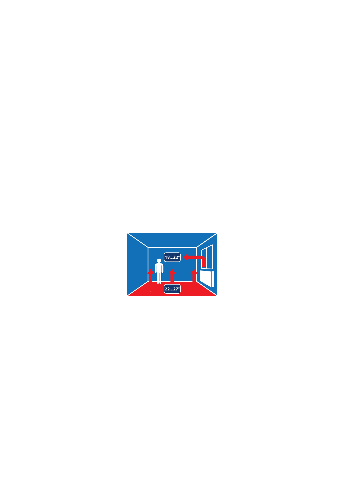
Optimal comfort
All heat moves upwards! This simple
fact explains why a floor heating system
provides more comfortable heat, than
the alternative radiator system. The
radiator system provides convective
air movement up to head height and
ceiling, only to travel downwards and
return as a cold draft around ones feet.
DEVI’s floor heating system, on the
other hand, provides pleasant heat
for ones feet, body and head.
As it produces only a very gentle
upward air movement the amount
of travelling dust particles is reduced
considerably making the system a
great asset to people suffering from
allergies or asthma. It also minimizes
presence of moisture at floor level.
Minimal energy consumption
Thanks to heat distribution from the
floor and precise temperature control
system with a DEVIreg™ thermostat,
the average room temperature can
be reduced by 1-2 °C compared with
traditional radiator heating, without
influencing the thermal comfort
or even improving it. This enables
reducing energy losses, from a
dwelling, by 10-20%, which is both
economically and environmentally
beneficial.
Flexible system
DEVI’s floor heating system ensures
comfortable room temperatures, be it
at home, at the office, in a workshop,
sports hall or virtually anywhere
where comfortable heat is required.
Equally important is the fact that
DEVI’s floor heating system can be
installed in all floor types whether
they are new concrete or wooden
floors or renovated floors.
Invisible heat source
DEVI’s floor heating system is invisible.
As the system is hidden under the
floor it gives exciting new possibilities
for furnishing and interior design and
the problem of space-consuming and
unattractive radiators (or heaters) no
longer has to be considered.
Ease of Installation
DEVI electrical underfloor heating
provided as a system, be it a
heating mat, cable with installation
accessories or a thermostat with easy
setup feature, quick and effortless
installation.
High durability, no maintenance
DEVI’s floor heating system has a long
life. Practically speaking DEVI’s heating
cables and mats last as long as the
house where they are installed and no
maintenance is required!
Quick and Precise Response Time
Electrical floor heating system has
a quick response time. Along with
DEVIreg™ intelligent thermostats
it also offers precise increase and
regulation of room temperature
comparing to water based
floor heating systems. System’s
responsiveness to temperature
changes and user adjustments is
also better.
20-year DEVI Warranty™ and
Full Service warranty
20-year DEVI Warranty™ is valid
for most of DEVI heating mats and
heating cables. DEVI support Full
service warranty for cables and mats
installed indoor for floor heating –
included costs for installation and
floor materials such as damage to
bricklaying and tiles. Full Service
20-year warranty implies that
when there is a warranty case DEVI
undertakes a responsibility to
correct the defect free of charge or
offer product replacement during
the warranty period. In addition,
DEVI covers all costs associated with
the replacement of any heating
system element and floor cover
restoration costs.
5Division · Cable Floor Heating Systems · VGLUH102 · ©DEVI
Page 6
3. Product overview
3.1. Cables
Electrical floor heating system
consists of two main components:
• Heating element (cable, thin
heating mat, or heating element
for laminate floors, etc.);
• Thermostat with air or/and floor
temperature sensors.
Heating cables are usually installed
in thick/concrete floor constructions.
The main feature of a thin heating
mat is its low thickness. This gives
the possibility for it to be installed
in a thin layer of tile glue avoiding
considerable increase of floor level.
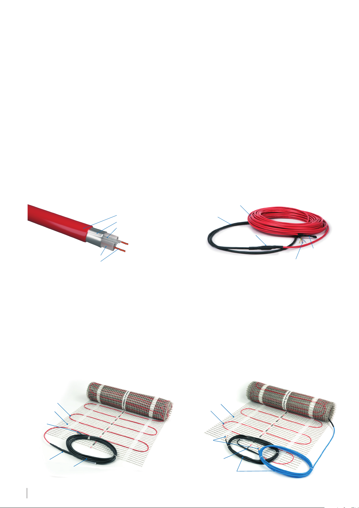
internal insulation ( XLPE)
heating element (resistance thread)
DEVIflex™ heating cable construction
DEVI heating cable (e.g. DEVIflex™)
is designed for installation in thick
concrete floor constructions. Usual
thickness of top/finish floor layer is
at least 3 cm. Heating cables used in
floor constructions are serial resistive
cables, preferably twin conductor,
but also a limited range of single
conductor cable is available. Cables
are manufactured as ready-to-install
heating elements with specific length
(i.e. 7, 10, 15, up to approx. 410 m),
with a power supply cable (cold tail)
and hermitically closed connections
(muffs or end terminations).
outer PVC coating
protective screen foil (Aluminum)
protective conductor
supply cable
Output of heating cables for
installation in floor constructions is
limited to 20 W/m and DEVI cables are
available with 6, 10. 18 and 20 [W/m]
for 230 and 400 V. Most DEVI cables
are manufactured and approved in
accordance with the latest version
of IEC 60800:2009, with mechanical
strength class M2 (for rough concrete
constructions). The main type of DEVI
heating cables for installation in the
floor construction is DEVIflex™.
Internal and external design of
modern DEVIflex™ cable is shown in
the figures below.
heating cable
connecting muff
end of the heating cable
connection to power supply
DEVIflex™ 6T/10T/18T heating cable
3.2 Mats
The thin heating mat is designed
for installation in a thin tile glue
layer adhesive, self-leveling mixture
or alike. The standard minimum
thickness of the floor layer is 5-8 mm
while the thickness of DEVI mats
is 3-4,5 mm. It allows minimizing
the floor level increase. DEVI thin
heating mats consist of a thin cable
fixed on self-adhesive glass-fiber
heating cable
adhesive mesh
connection to
power supply
connecting muff
supply cable
DEVImat™ 100T/150T Heating mat
mesh usually of 50 cm width. Thin
heating cables are serial twin or
single conductor resistive cables.
Thin heating mats are manufactured
as ready-made heating sections with
a specific area (i.e. 0,5, 1, 1,5 … 12 m²)
including a power supply cable
(cold tail) and hermetically sealed
connections.
adhesive mesh
heating cable
connection to
power supply
connecting muff
supply cable
DEVIheat™ 150S Heating mat
Thin heating mats are available with
various outputs, for example: 70 W/
m², 100 W/m², 150 W/m² and 200 W/
m². DEVI thin heating mats comply
with IEC 60335-1 & IEC 60335-2-96.
The most commonly used DEVI
twin conductor heating mats for
installation in the floor construction
are DEVImat™ and DEVIcomfort™.
6 Division · Cable Floor Heating Systems · VGLUH102 · ©DEVI
Page 7
Center-to-center distance between
mat’s cable lines is usually 7,5 cm. It
allows even distribution of heat on
the floor surface avoiding cold zones
between the cable lines.
The modern thin twin conductor
DEVImat™ and single conductor
DEVIheat™ are shown below.
3.3 Thermostats
DEVI heating cables and thin heating
mats mentioned above are the most
used floor heating elements. DEVI
also produces other floor heating
elements, i.e. DEVIdry™ and DEVIcell™
heat distribution panels for heating
constructions with wooden surface
(laminate, multi-layer boards,
parquet, etc.) or/and on wooden
subfloors. DEVIdry™ has 55 and 100
W/m² outputs.
For further information please refer
to the DEVI Product Catalogue.
DEVI offers specialized thermostats
for electrical floor heating systems.
All thermostats are electronic devices
allowing precise control of the
floor surface or air temperatures. In
general three types of thermostats
are available:
• for air/room temperature
control and limitation of floor
temperatures – with room sensor
and floor sensor;
• for floor temperature control –
with floor sensor only;
• for air/room temperature control –
with room sensor only.
DEVI offers thermostats that are:
• Intelligent, PWM (Pulse Width
Modulation regulated)
• Simple (hysteresis regulated).
Intelligent thermostats provide stateof-the-art wireless control system for
control of heating and electrical units
in private houses. Some thermostats
are fitted with Wi-Fi allowing remote
control of heating systems via mobile
application.
Simple thermostats are electronic
control units with or without
display allowing setting the heating
system type, adjustment of control
parameters and timer mode.
NEW!!
Adjust your
floor heating
from your
smartphone
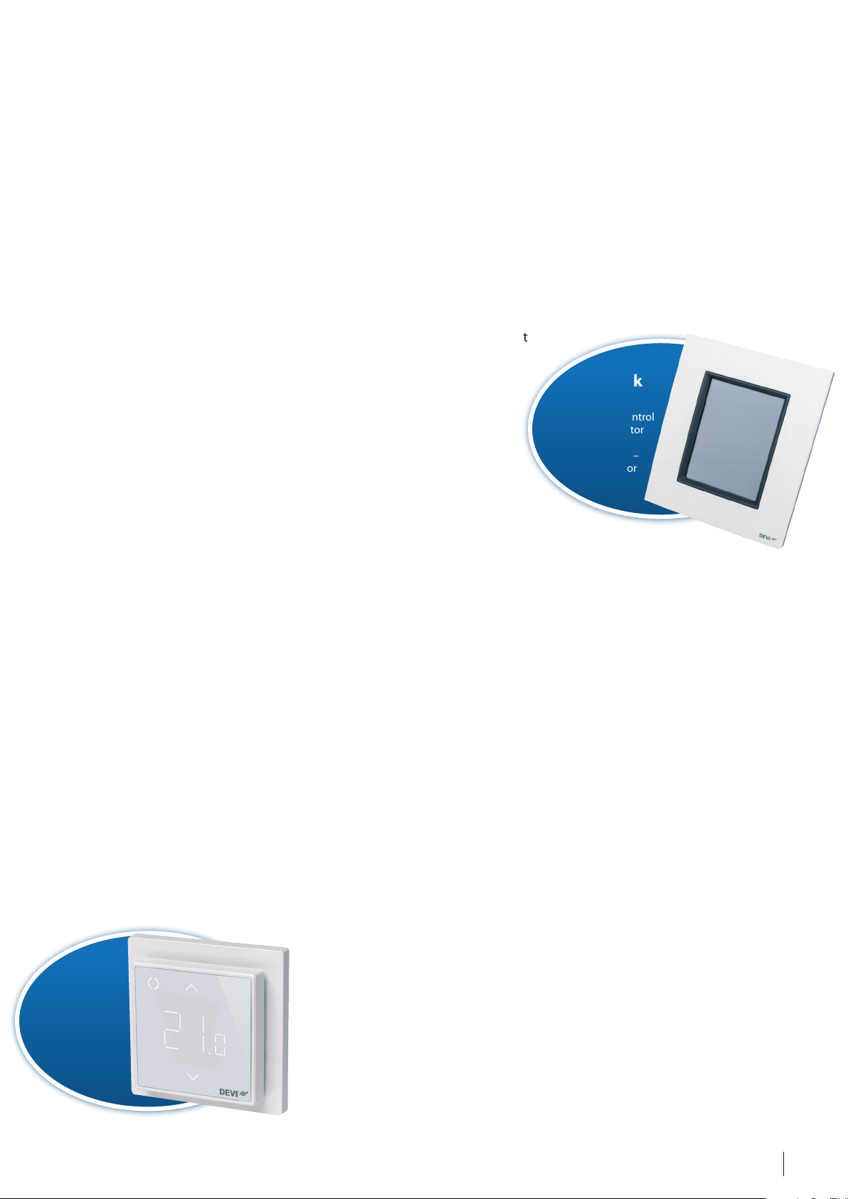
DEVIreg™ Smart
DEVIreg™ Smart is the DEVI’s latest
solution and a further development
of, the very well known DEVIreg™
Touch with Wi-Fi control via mobile
application, unique Nordic design
and advanced user experience,
with application that enables up
to 10 different users to control
electrical heating systems from
anywhere in the world using a
smartphone or a tablet.
DEVIreg™ Smart is an intuitive
programmable intelligent timer
thermostat used for controlling
electrical floor heating elements.
The thermostat is designed for flushmount installation into a standard
wall installation box, or on wall with
a special on-wall box. Due to the
special 2-part construction it fits a
wide range of frames and sensors.
DEVIreg™ Smart builds further on
energy saving functions introduced
earlier in DEVIreg™ Touch, like:
• fast and intuitive setup using the
built-in wizard;
• energy-saving program –
including optimum start/end
control ensuring the desired
temperature at the correct time
and thereby reducing heating
costs;
• open window function;
• very precise regulation of user set
room temperature by means of a
specially developed PWM (Pulse
Width Modulaton) regulation,
including optimal change from
comfort to economy mode.
DEVI Link
system
covers the control
of both radiator
heating and
floor heating –
individually or
combined
DEVIlink™ CC
DEVIlink™ CC (Central Controller)
is the central brain in the DEVIlink™
system which includes several
wireless DEVIlink™ devices installed
inside the building.
Several functions, i.e. room control,
intelligent timer, modes for the whole
house – “Away”, “Comfort”’, “Frost
Protection”, are integrated into the unit
to reduce energy consumption when
using electrical floor heating system.
The idea of the DEVIlink™ System is
to provide wireless connection of
your heating system and to control it
from one central point. The DEVIlink™
CC communicates wirelessly with
all other DEVIlink™ units of the
installation. A single DEVIlink™ CC
can control up to 30 rooms and
allows connection up to 50 units and
specially developed to satisfy the
needs of any family house: it can
be also used for apartments, and
multifamily buildings.
DEVIlink™ is fitted with Danfoss
Link™ App, and the latest version
provides the possibility of Wi- Fi
control by mobile application,
anywhere in the world.
7Division · Cable Floor Heating Systems · VGLUH102 · ©DEVI
Page 8
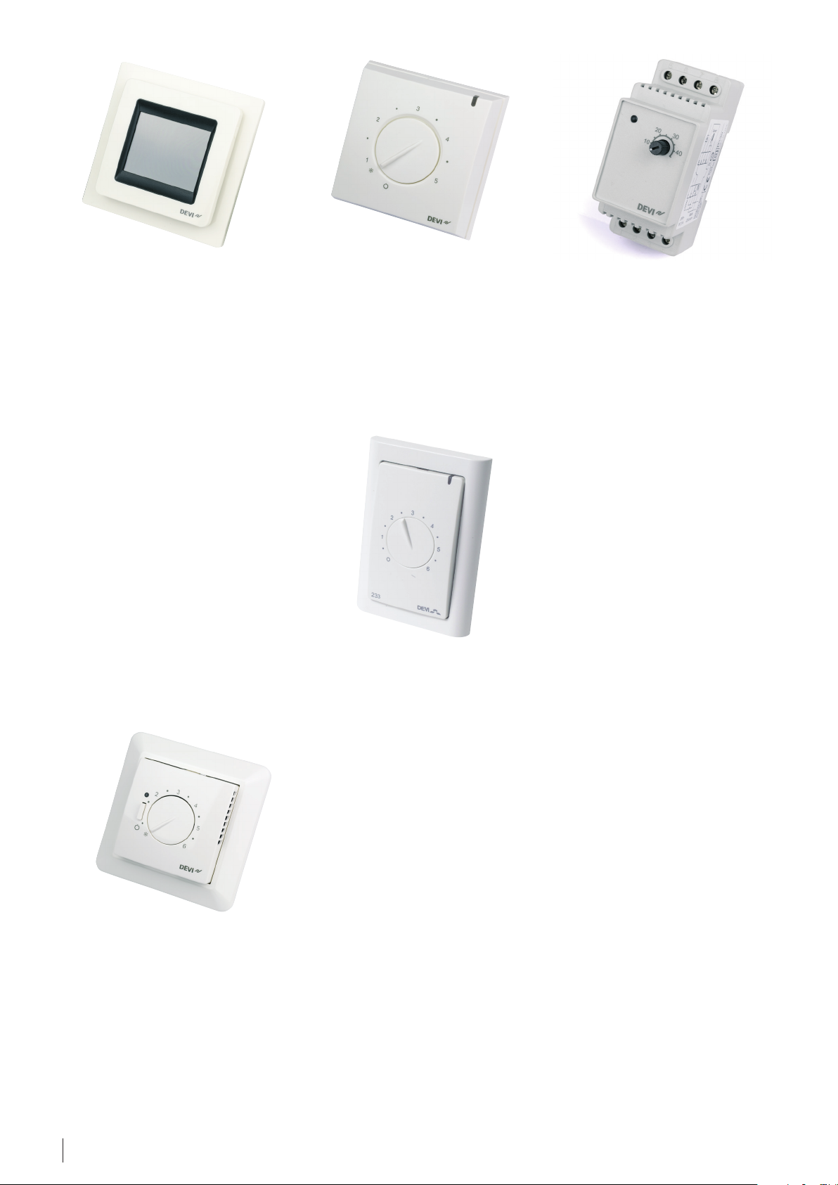
DEVIreg™ Touch
DEVIreg™ 130
DEVIreg™ 330
DEVIreg™ Touch is a thermostat
fitted with a display and an intelligent timer. It is designed for flushmount installation into a standard
wall installation box. It operates with
two sensors – floor wire and built-in
room sensor. It allows control setting
for one of 3 heating systems: with
wire floor temperature sensor, with
built-in room sensor or with built-in
room sensor and wire floor sensor
for limitation of floor temperature.
The touch screen menu and intuitive
user friendly interface allow easy use
and quick service. The thermostat
has four original colors – polar white,
pure white, ivory and black. It can be
installed in complex frames of different manufacturers.
DEVIreg™ Touch is fast and intuitive to
setup using the built-in wizard. It has
an energy saving program – including
optimum start/end control ensuring
the desired temperature at the correct
time and thereby reducing heating
costs.
DEVIreg™ 13x series thermostats
are designed for mounting directly
on the wall. Following models are
available:
• DEVIreg™ 130 with wire
temperature sensor;
• DEVIreg™ 132 with built-in room
sensor and wire floor sensor for
limitation of floor temperature.
DEVIreg™ 233
DEVIreg™ 233 is an electronic
thermostat designed to be flushmounted in an installation box
from the LK FUGA series frame. The
thermostat is provided with a single
pole switch and a floor sensor (wire)
to measure and control the desired
floor temperature. Alternatively an
external room sensor can be used, for
room temperature regulation.
The thermostat has a button to adjust
the temperature setting in the range
of (0) 1 to 6.
DEVIreg™ 330 (5…45°C) – is an
electronic thermostat to be installed
in electric cabinets with DIN rail
attachment. The set includes wire
temperature sensor. To control room
temperature an external air sensor is
required.
DEVI offers over 20 different types
of thermostats. The product range
includes easy to operate (by APP)
intelligent Wi-Fi control thermostats
to specifically designed digital,
thermostats with moisture sensors
for ice and snow melting on ground
as well as ice protection for roofs and
gutters (refer to Ice & Snow melting
Application Sheet). DEVIlink™ and
DEVIreg™ Smart system is equipped
with wireless functions and Wi-Fi
control of heating systems and
indoor electrical equipment.
DEVI provides a unique solution –
that is “top quality intelligent heating
system”, giving consumers the
highest level of comfort and safety!
The intelligent component of these
systems is the DEVIreg™ electronic
thermostat which is available in
several options, i.e. for total heating
or comfort floor heating.
More information about DEVI
thermostats you can find further
in this document and in the DEVI
Product Catalogue.
DEVIreg™ 530
DEVIreg™ 53x series thermostats are
designed for flush-mount installation
into a standard wall installation box.
Three models are available:
• DEVIreg™ 530 with wire temperature sensor;
• DEVIreg™ 531 with built-in room
sensor;
• DEVIreg™ 532 with built-in room
sensor and wire floor sensor for
limitation of floor temperature.
8 Division · Cable Floor Heating Systems · VGLUH102 · ©DEVI
Page 9
4. Heating systems in floor constructions
Electrical floor heating systems for
indoor heating can be divided into
3 main heating categories (types):
• Comfort floor heating;
• Total or Direct heating;
• Accumulating heating.
4.1. Comfort Floor Heating
4.1.1. About the system
Comfort Floor Heating or “Warm
Floor” system provides heated floor
surface, in any rooms, and especially
used for bathrooms and kitchens.
Comfort floor heating can be used
in any room fitted with another
heating system to provide required
air temperature, for example water
based radiators on the walls. Warm
Floor/ Comfort heating installed
in such premises only maintains
constant floor temperature at all
times, regardless of the heating
season. As an additional benefit
the Comfort heating increases air
temperature in the room, and due to
large heated floor surface will allow
compensation of inadequate heating
during extremely cold winter days
or in case of lack of heat regulation
in rooms which are not fitted with
a modern thermostat controlled
room heating systems. Comfort
floor heating system is controlled
by a thermostat with a floor sensor
(usually wire sensor). The heating
element is activated by a thermostat
based on the floor temperature set
by the user.
A comfortable floor temperature
has been evaluated many times, for
example, described in standard ISO/
TS 13732-2. The maximum long term
comfort floor surface temperature
is defined at the level of 29,5 °C.
Additionally: sedentary people
needed extra 1-2 °C. For floors in
wet rooms maximum temperature
can reach 31 °C. These maximum
temperature values can be used for
calculation and selection of installed
outputs (in [W/m²]) of comfort floor
heating systems. Different types of
floor surfaces need different comfort
floor temperatures, e.g. wooden
floor surface has an optimal comfort
temperature of approximately 26
°C, carpet – approximately 24 °C.
But it is impossible to predict type
of floor surfaces during life time of
floor construction, as well as that
comfort temperature is perceived
differently by different individuals. It
is advised to use maximum comfort
floor temperature level to satisfy all
possible options, but often a floor
temperature few degrees above
the current room temperature will
already satisfy the needs of most
users. It is important that most of
wooden floor surfaces have limitation
of max. temperature at the level of
27 °C (for more details concerning
maximum allowed temperatures
of the floor surface please refer to
a manufacturer of wooden floor
materials).
EXAMPLE:
The optimal required output (in
[W/m²]) for comfort floor heating
system, can be evaluated by a simple
calculation. Assuming that the room
temperature is 20 °C (supported by
another heating system during the
heating season) and the floor surface
needs to reach up to 29 °C. The floor
temperature must be increased as
follows: 29 - 20 = 9 °С. Information
about the installed output (in [W/
m²]) needed to heat up 1 m² of
floor surface to 1 °C can be found in
physic books and standards (e.g. DS/
EN 1264. Heat exchange coefficient,
usually named alfa – α [W/(m²·K)], can
vary, however for general evaluation
α =10 W/(m²·K) can be used.
This will be described in details on
the following pages.
Consequently to heat 1 m² of floor up
to 9 °С in relation to air temperature,
approximately an installation of
9 °С · 10 W/(m²·K) = 90 W/m² is
required.
As a “rule of thumb” a safety value of
30% should also be added offering
a minimum output for electrical
heating element used in comfort
floor heating system as calulated in
the following example:
90 W/m² · 1,3 ≈ 120 W/m²
Recommendation: output for
comfort floor heating systems should
be no less than 120 W/m², unless any
special restrictions are specified.
The following power outputs for
comfort floor heating systems
are recommended based on floor
constructions, insulation levels,
surface types, room air temperature
and individual user preferences:
• Wooden floor constructions – no
more than 100 W/m²;
• Dry rooms, thermal insulated
floors – 100 W/m² or more;
• Floors without thermal insulation –
130-160 W/m²;
• Wet rooms – 150-180 W/m²;
• Low voltage, insufficient insulation,
covered balcony slabs –
160-200 W/m²;
• maximum output in floor
construction – should not exceed
200 W/m².
Find more details and restrictions for
special floor constructions such as
wood, later in this document.
9Division · Cable Floor Heating Systems · VGLUH102 · ©DEVI
Page 10

Comfort floor heating systems do
not require heat loss calculation. It
is advised to install power at least
100 W/m² in all dry premises, and
at least 150 W/m² in wet premises,
however note that norms for wooden
floors specify no more than 100 W/
m², and require a thermostat with a
floor sensor to limit maximum floor
temperature. Heating system must
be controlled by thermostat and it is
worth mentioning that installation
of increased power, e.g. 150 W/m²
instead of 100 W/m² does not affect
energy consumption of the system,
but can influence user comfort
feeling.
C-C distance
Heating cables are installed inside
floor construction with some
distance between them (or so called
installation step, centre-centre
or cable-to-cable distance: C-C
distance). To achieve a warm floor
with even distribution of heat and
to provide comfortable temperature
on the floor surface, the floor surface
temperature variation should not
exceed 1,5 °С (e.g. DIN 44576).
There will always be a difference in
temperature on the floor surface, in
areas between heating cables and
directly above them. The bigger C-C
distance – thicker layer of concrete
above cable is necessary to ensure
a uniform/comfort temperature
distribution along the floor surface.
This difference is always more
pronounced during periods, when
electrical heating cables are turned
on (providing heat to the floor
heating). The instant thermostat
disconnects the heating cables,
because desired floor temperature
is reached, the temperature on the
top of the floor surface is equalized
greatly, giving an increasingly
comfortable floor surface.
A rule of thumb indicates:
• The thickness of concrete & floor
structure above the heating cables
need to be ~½ the C-C distance.
Here is the additional explanation:
For Warm Floor system installed
into a thick concrete slab the
C-C distance of 5-10 cm is
recommended. The thickness of the
concrete slab top layer is usually
not less than 3-5 cm, regardless
whether heating cables are to be
installed there or not. For thin floor
constructions, such as tile glue,
laminate etc., the C-C distance
should not exceed 10 cm and is
recommended to be even less: 7,5
cm. To install heating cables under
the tile glue the best solution is
DEVI thin heating mats with
C-C = 7,5 cm that guarantees floor
surface without cold zones.
Recommendation: it is always
advised to insulate the floor structure
below the heating cables.
More details about cable installation
step (C-C distance) and appropriate
outputs are described below in this
document.
Thermostat with floor sensor:
The thermostat uses a wire sensor to
measure the temperature inside the
floor construction. The sensor needs
to be placed directly between, and if
possible, slightly above the lines of a
heating cable or a mat. Temperature
measured by the floor sensor is
not the real surface temperature
and depends on placement of the
floor sensor. It is difficult to give
any recommendations about the
thermostat settings for a specific floor
construction.
The thermostat with a floor sensor
has a scale without degree marking.
4.1.2. System Design
Following stages will help you to find
a right solution for your comfort floor
heating system (more about DEVI
products find in the DEVI Product
Catalogue):
Choice of a heating element type
(mat or cable).
Define the thickness of floor
construction over the cable, and a
type of the installation. For example
for renovation, where small floor
structure needs to be enlarged, a
heating mat is a preferable solution
due to the element’s height.
If you plan to increase the floor
construction by less than 30 mm,
it’s preferred to use a heating mat,
suitable for floor increase of 3-5 mm.
If you plan to increase the floor
construction by more than 30 mm,
a heating cable is usually applied.
It should be noted that there are
no restrictions for use of heating
mats in concrete or thick floor
constructions. The question of
thermal insulation, installation
thickness in floor construction should
also be addressed, as it’s important to
minimize heat losses downwards.
Choice of specific output.
Specific output (p in [W/m²]), for
Comfort Floor Heating usually does
not require calculation and is selected
from recommendations for specific
floor construction and environment.
For standard floors without insulation
the output of no less than 100 W/m²
is usually chosen and for wet rooms –
no less than 150 W/m². In the lack of
reliable information about the floor
construction, flooring type, supply
voltage, etc., it is better to choose
an output as close as possible to the
maximum recommended (see page
above).
To fix heating cables DEVIfast™ fitting
bands are usually applied, it offers
a cable attachments with a step
distance (C-C) of 2,5 cm.
This leads to the situation that the
value of the specific output for a
heating cable cannot be chosen
arbitrarily, and it should be taken
into consideration that the cable can
be installed at 2,5 cm intervals only,
and respectively output will match
attachment distance.
For example if:
• cable is DEVIflex™ 18T,
• supply voltage is 230 V,
• the C-C distance of 12,5 cm
gives output of 145 W/m².
And for installation step with the
C-C of 10 cm – 180 W/m² (see the
DEVI Product Catalogue for product
selection). Thereby, for heated area
the value of the specific output - p
INST
[W/m²[, which is actually installed,
should be chosen for fixed C-C,
following the table or calculated
value.
It should be noted that in some
countries the supply voltage is lower
than 230 V that leads to decrease
of the cable specific output and
respectively, different [W/m²] with
10 Division · Cable Floor Heating Systems · VGLUH102 · ©DEVI
Page 11

the same step (C-C). For example,
if the given output is 230 V the
coefficient of 0,915 should be applied
with 220 V supply.
Estimation of heated floor area.
Installation area of heating cable/mat
has to be calculated A
[m²]. To do
INST
this, from the total area of the room
(in [m²]), the area under stationary
objects (bath, toilet, shower, cabinet,
cupboards, etc.) and a strip of free
floor along walls (usually 10-15 cm
wide) is deducted, as well as special
customer’s preferences should be
taken into account.
The heating cable or mat is set
into the floor for many years, so it’s
advised to exclude from heated area
items/furniture that can be moved
over the operation life of the premises:
cupboards, cabinets, bed etc.
Along the interior walls, where
any furniture most probably will
be located up to 30-40 cm can be
allowed. For heating systems installed
in the floor construction, furniture
on legs, that provide air circulation
underneath is recommended.
Choice of a specific heating
element (length of heating cable or
area of heating mat).
Heating cable is normally chosen
based on required heating output
for room (the calculated total output
P
[W]). This output is calculated as
CALC
the chosen specific output
P
[W/m²] multiplied by the installa-
INST
tion area A
P
[W] = P
CALC
[m2]:
INST
[W/m²] · A
INST
[m²]. The
INST
heating element is selected from the
product list of factory-produced elements, with specific output P
INST
[W].
Always the product nearest to, but
larger than, calculated total output
P
[W], is to be chosen. For indoor
CALC
heating DEVI recommends to use
screened twin conductor DEVIflex™ 18T,
DEVIflex™ 10T, DEVIflex™ 6T heating
cables or if nothing else is suitable, a
screened single conductor
DEVIbasic™ 20S heating cable.
The number at the end of the cable’s
name refers to: its specific output for
1 m in [W/m] at 230 V, and letter “T”
means a twin conductor cable (Twin),
letter “S” - single conductor cable
(Single).
The most frequently used cable type
is DEVIflex™ 18T – twin conductor,
18 W/m at 230 V (16,5 W/m at 220 V).
A linear output of DEVIbasic™ of
20 W/m, is not the best choice for
even temperature distribution along
the floor construction, if installed in
the same floor, compared to
DEVIflex™ 6,10 or 18 W/m.
The heating mat is selected from a
range of factory-produced elements
(covering area from 0,5 to 12 m²),
with an area covering usually the
nearest less value to available
installation space A
installation area (A
[m²]. If the
INST
[m²]) exceeds
INST
12 m², a multiplication of chosen
heating mats needs to be applied.
For example, DEVI screened heating
mats designed for floor installation
have the cable/mat thickness for:
• twin conductor of ~3,0 mm:
DEVImat™ 70T, DEVImat™ 100T,
DEVImat™ 150T, DEVImat™ 200T;
• twin conductor of ~4,0 mm:
DEVIcomfort™ 100T, DEVIcomfort™
150T;
• single conductor of ~3,0 mm:
DEVIheat™ 100S or
DEVIheat™ 150S.
The number at the end of a mat’s
name refers to its specific output for
1 m² in [W/m²] at 230 V, and letter “T”
means twin conductor mat (Twin),
letter “S” a single conductor mat
(Single). A single conductor heating
mat requires more planning before
installation, to ensure that the power
supply cord attached to both ends
of the heating mat starts and ends at
the same place.
For Comfort Floor Heating
DEVImat™ 150T and DEVIcomfort™ 150T
heating mats are used most often –
twin conductor, 150 W/m² at 230 V
(135 W/m² for 220 V ).
Calculation of the fitting band
length (DEVIfast™).
If heating cable is applied, it is
recommended to use fitting band to
fix it to the floor base. For example,
metal galvanized DEVIfast™ fitting
band. It is attached to the floor
(nailed or fixed with screws or glued)
in parallel lines, usually every 50 cm.
This equals to two (2) meters of band
for each square meter [m²] of cable
installation.
Simple calculation of the fitting band
length L
(m): cable installation
FIX
space is multiplied by two, e.g.
L
= S
FIX
· 2 (m).
INST
Thermostat selection.
Thermostat for Comfort Floor Heating
system should be fitted with a floor
temperature sensor.
Choice recommendations:
heating area is larger than 5 m² –
programmable thermostat with
timer, for example, DEVIreg™ Smart;
smaller than 5 m² – simple one
without a timer, for example,
DEVIreg™ 530 or DEVIreg™ 130, can
be chosen. Simple thermostats are
only recommended due to their
lower cost, and as there are no
restrictions for use of thermostat with
timer for small areas.
The maximum output (in Amperes),
that thermostat is able to switch on
usually varies between 3450-3600 W
(15-16 A). This needs to be taken into
consideration for larger rooms. If
more than maximum 3450-3600 W is
needed the following two solutions
are possible:
1. Heating area is divided into
independent zones with separate
cables and individual thermostats.
Each zone not exceeding the
connected output indicated
above, and with the same output
(in [W/m²]) installed;
2. Contactor (additional relay) with
increased maximum current is
used (e.g. 20 A or more), usually
mounted on a DIN rail in the
electrical switchboard.
Recommendation: it is advised to
choose thermostat load of 70-80% of
maximum installed output.
Choice of additional equipment.
Mounting box for thermostat,
conduit pipe for floor temperature
sensor, screws, nails or anchors for
attaching fitting band to the floor, etc.
It is assumed that the voltage supply
is stable and properly connected,
11Division · Cable Floor Heating Systems · VGLUH102 · ©DEVI
Page 12
according to electrical laws of the
country of installation e.g. fuse and
RCD (Residual Current Device) are
of power supply cable are properly
chosen. Otherwise these elements
have to be selected too.
installed in switchboard, section and
length and cross section area
4.1.3 Design Example. Calculation and selection of equipment
Floor construction.
Follow installation instructions
provided by manufacturers of
floor elements, and local building
regulations.
Comfort floor heating for
bathroom.
Input data: bathroom, 2nd floor (over
heated room), no floor insulation,
size 3 x 4 m, total area of 12 m², with
installed 0,9 х 1,7 m bathtub, stable
power supply voltage of 230 V, floor
surface made of tiles.
Restrictions for the floor height: can
be increased maximum by 2 cm.
Heating mat or cable?
Since the floor height is an issue
the concrete thickness is less than
3 cm. Choose a mat, DEVImat™
or DEVIcomfort™ twin conductor
screened mat (find a detailed
description of products in the
DEVI Product Catalogue).
Installed output.
Wet room, stable voltage, 2-nd floor,
tiles, heated room below: an output
of 150-180 W/m² (chapter 4.1.1) is
recommended.
Calculation of heated floor space
(area of cable installation).
Out of the total space A (in [m²])
bathtub area (0,9 х 1,7 m) and strips
of floor of 10 cm along the walls are
subtracted:
A
= 12 m² – (0,9 m · 1,7 m) – ((3 m + 4 m) +
INST
+ (3 m – 0,9 m) + (4 m – 1,7 m)) · 0,1 m =
= 12 m² – 1,53 m² – 1,14 m² ≈
≈ 9,33 m².
Select the desired mat size.
Available floor area is 9,33 m².
DEVImat™ 150T covering 9 m² of
floor, and with total output of 1235 W
at 230 V, is chosen.
If the mat covering 10 m² of floor is
chosen, there will be a surplus of
0,67 m² of mat, and since it’s not
allowed to cut or shorten a heating
cables and mats, the mat covering
9 m² of floor is a preferred choice.
Fitting band.
It is not needed, since DEVImat™ has
a self-adhesive glue on the underside.
We advise to clean the floor and
remove all debris and dust.
Thermostat selection.
DEVImat™ 150T with 1235 W output,
less than 3450- 3680 W maximum
allowed, can be connected to a
DEVI thermostat. For the heating
area exceeding 5 m² – thermostat
with a timer is recommended. For
example, choose the most modern
programmable WiFi thermostat with
intelligent timer – DEVIreg™ Smart.
Type System Temperature sensor Range IP class Load, max.
DEVIreg™
Programmable:
Air: embedded,
Floor 5…45 °С.
IP21 3680 W
Smart
Comfort Floor Heating or Heating
with floor temperature limiting
As an option, simple thermostat
with floor sensor can be chosen:
e.g. DEVIreg™ 530. When thermostat
is installed in a wet room, the
requirements of electrical safety
norms and corresponding IP
class should be strictly followed!
It is recommended to install the
thermostat outside the bathroom.
Additional equipment.
Electrical materials necessary for
installation will typically include
the following: wall mounting box
for thermostat, 4-5 m conduit pipe
for a floor temperature sensor and
additional power supply if necessary.
It is assumed that there is a proper
power supply, according to the rules
Floor: included wire
sensor
Air 5…35 °С
and regulations for safety elements
of electrical installation, e.g. fuse and
RCD are installed.
Summary:
For comfortably warm floor in 12
m² bathroom (with free area of 9,33
m²), the following DEVI floor system
elements are recommended:
Equipment Characteristics Quantity
Twin conductor screened DEVImat™ 150T
9 m² 1235 W (at 230 V), (150 W/m²) 1 pcs.
heating mat
DEVIreg™ Smart thermostat Programmable, WiFi, APP enabled, intelligent timer,
1 pcs.
air and floor sensors, IP21
Conduit pipe Ø 16 4 m
Mounting box 1 pcs.
12 Division · Cable Floor Heating Systems · VGLUH102 · ©DEVI
Page 13
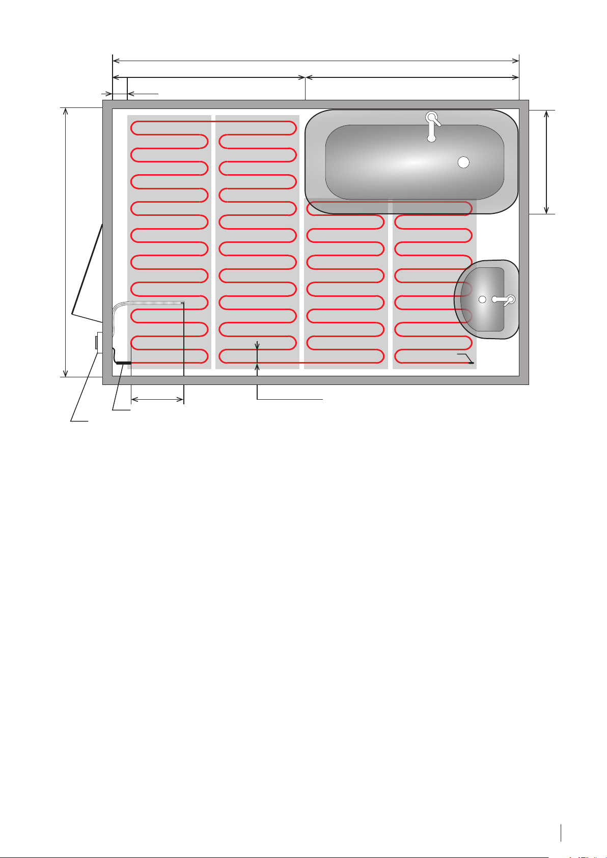
4
2,3 1,7
0,1
0,9
3
Temperature sensor in corrugated pipe
0,5
0,075
C-C distanceConnection muff
Thermostat
Figure 1 – Example of heating mat installation in bathroom. All distances are in [m].
4.2. Total (Direct) floor heating
4.2.1. About the system
Total or Direct electrical floor heating
is the only heating system installed
in a room (or area) for maintaining a
user specified room temperature. It
is ensured by adjusting floor surface
temperature, due to the changeable
heat transfer from the surface of
the floor. Such a system is regulated
by a thermostat with air & floor or
only room temperature sensor. Air
room sensor is an integrated part
of DEVIreg™ room thermostats. A
floor heating system has a large
heated surface of the floor, and it is
a convection and radiation heating
system. Advantage of a floor heating
system is to provide heat in the
lower part of a room near legs and
relatively less heat around room
ceiling, where it’s not so highly
needed. It is proven by many studies,
that such temperature division is the
most comfortable for any person,
independent of gender, age and
activity level. Floor heating system
provides a feeling of the same or
improved thermal comfort at lower
overall room temperature setting.
As a result, it can be lowered by app.
1...2 °C, compared with an earlier
used radiator heating system, with
heating element installed visibly
under the window. This provides a
user with improved thermal comfort
and energy savings of approximately
10-20%.
Output of a heating system is chosen
based on the level of calculated
heat loss (in Watts). Energy, which is
provided via a floor heating system,
must cover heat loss and support
a specified air (room) temperature.
End muff
Usually a safety factor of 20-30% is
added to the heat loss calculated
output value, depending on room’s
specific thermal condition. As the
heating system is controlled by a
thermostat, installing larger power
output does not affect the overall
consumption of electrical energy for
heating.
Total electrical floor heating, “Heating
via floor” should not be confused
with “Comfort Floor Heating/Warm
Floor”. The need for warmth is
variable, because of the changing
outside temperatures during the
heating period, and accordingly
floor temperatures varies too. As
an example, in October, when the
outside temperature is +5 °C, it
would be enough to heat the floor
up to 21...22 °C to maintain indoor
temperature of 20 °C. But in February,
13Division · Cable Floor Heating Systems · VGLUH102 · ©DEVI
Page 14
when the outside temperature is
lower e.g. -15 °C, floor will be heated
more e.g. 25...26 °C, to maintain the
same room temperature.
When utilizing floor heating system
for total heating you should always
choose as technically correct
solution, but observe the limitation
of the maximum floor temperature.
For regulation of a total heating
system a thermostat measuring
air (room) temperature and fitted
with floor temperature sensor is the
preferred choice. Allowing setting
maximum floor temperature level
and constantly monitoring prevents
overheating of floor. Such limitations
are strictly necessary for floors with
wooden surface.
Special DEVI thermostats are used
where setting of the maximum
floor temperature is necessary or
advisable:
• in programmable models: by
setting of special option.
• in simple models: by manual
potentiometer under the
thermostats cover.
Factory default setting for maximum
floor temperature limit is 35 °C.
Even if a specific floor installation
doesn’t particularly require a floor
sensor to be installed, it’s strongly
advised to do so. Install a plastic pipe
conduit where, at later date, floor
sensor could be fitted. The heating
element (cable or mat), is installed in
the floor construction where it forms
parallel lines. When using a heating
cable: output density of heating
system (in [W/m²]) is determined
by C-C distance (cable-to-cable or
center-to-center distance) of heating
cable. Increasing the distance
between cables leads to decreasing
of output and vice versa. When a
desired output density is calculated
and chosen, than C-C distance,
that will determine the number of
cable lines per 1 m² of floor or the
cable length per 1 m² is calculated.
Multiplying the chosen cable length
on a total area of heating cable
installation will give the calculated
length of heating cable.
C-C distance (cm) =
Available floor area (m²) · 100 (cm/m)
=
Length of chosen cable (m)
Detailed information about cable
installation procedure is found later
in this document.
For modern houses or dwellings
calculated heat loss is small and,
consequently, the output of floor
heating system is also limited. As a
result, to prevent a heating cable
from being installed with a large C-C
distance, it’s advisable to use one
with less linear output. For example,
for calculated heat loss of 50 W/m²,
when using the most common
DEVI cable: DEVIflex™ 18T, the C-C
distance will be as big as 36 cm. That
will inevitably lead to a floor surface
pitted with cold zones situated
between lines of the installed heating
cable. As aim for a floor heating
system is to achieve and maintain
a constant and comfortable floor
temperature, for heating systems
with required low specific output,
we recommend heating cables with
lower linear output (in [W/m²]): for
example DEVIflex™ 10T or DEVIflex™ 6T.
This allows reduction of C-C
distance and leads to a more even
temperature division on the floor.
Safety coefficient.
For heating systems installed in
floor structure, it’s necessary to add
a safety coefficient of 1,2-1,3, when
designing a power output that needs
to be installed in the floor. This factor
is an experience value used by the
industry, and is based on following
facts:
• heating cables length, resistance
and wattage tolerance,
• power supply voltage has some
accuracy,
• heat loss downwards, floor
buildup, and surface material type.
Floor surface temperature.
It should be taken into account that
the big heat loss leads to necessity
of big output from a heating
system and, accordingly, to high
and perhaps not a comfortable
temperature on the surface of the
floor. The maximum temperatures
of the floor surface for different
types of applications are specified in
the relevant standards. For a rough
estimation of the possible floor
temperature for a given output the
value of heat exchange coefficient of
α =10 W/(m²·K) (more description is
found in paragraph about Comfort
floor heating) should be used. For
example, if the output of the heating
system is 150 W/m² and heat loss
down is ~ 20%, than the heat flow up
is 150 – (150 · 20%) = 120 W/m².
If actual heat loss is close to that
value, it will imply a requirement
of an increase of a floor surface
temperature with as much as 12 °C
(120 W/m² /10 W/(m²·K) in relation
to air temperature. E.g. if the air/
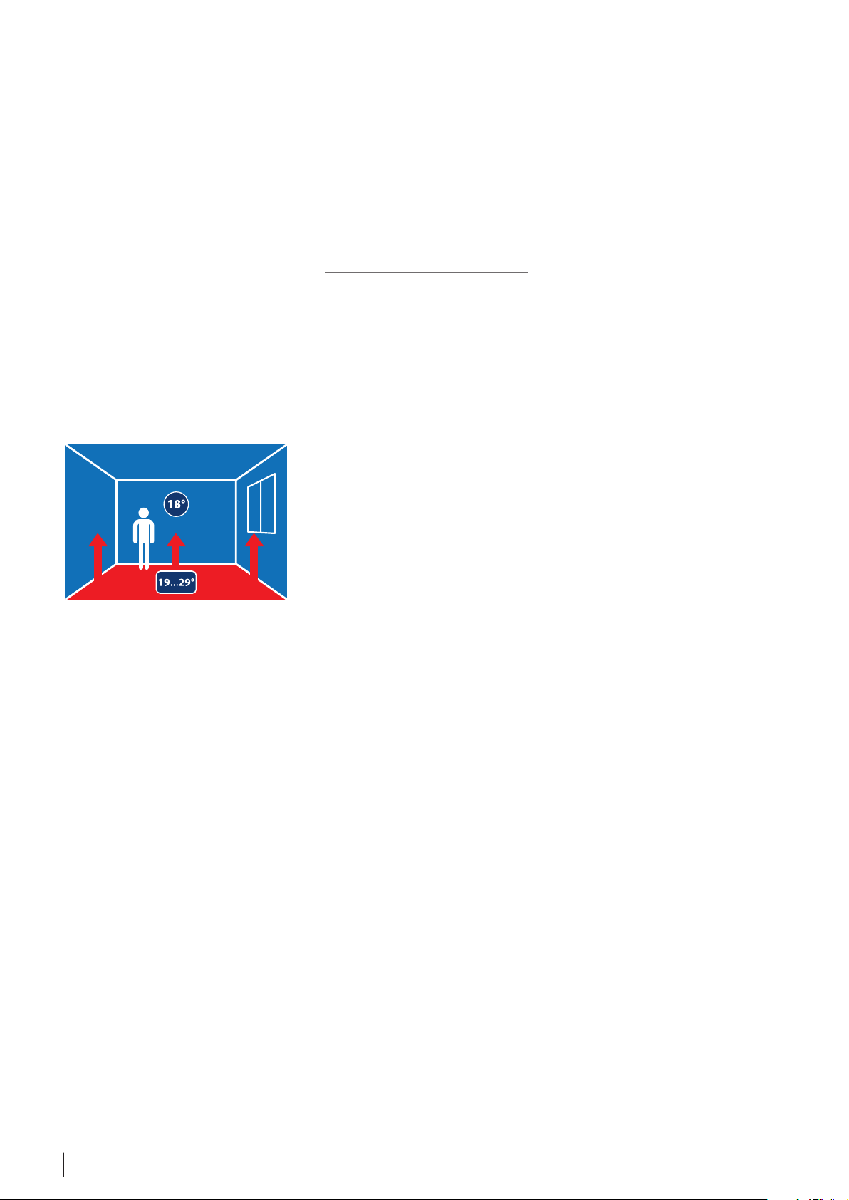
room temperature is 18 °C, the floor
temperature can reach 18 + 12 = 30 °C
in the coldest time of the year to
satisfy the rooms actual heat loss.
4.2.2. Calculation and selection of
elements/products
For more detailed information refer
to the DEVI Product Catalogue and
previous chapters of this document.
Estimation of a heating system’s
calculated output.
Define heat loss of the premises
Q [W]: from documentation or by
calculation (e.g. EN 12831).
Floor heating system calculated
output is determined with taking into
account a safety factor of 1,3:
P = Q · 1,3 [W].
Choice of a specific heating
element (mat or cable).
Define the thickness of floor
construction over the cable. If
planned concrete height is 3 cm
or more, heating cable is usually
installed, if floor construction is thin
(tile adhesive, etc.), heating mat
(with thickness of ~ 3-4,5 mm) is a
preferred choice. It should be noted
that there are no restrictions for use
of heating mat in concrete or thick
floor construction.
14 Division · Cable Floor Heating Systems · VGLUH102 · ©DEVI
Page 15

It’s strongly advised to install
insulation in the floor construction
if possible. Its thickness should be
selected according to local norms.
When heating system works for a
fairly long period during the year
(e.g. in the Nordic countries for
6-8 months per year), thickness of
thermal insulation in the floor has a
direct influence on level of heat loss
and therefore additional electricity
costs. For the durability of the floor
construction concrete installed
over/onto insulation, has to have
a thickness of at least 3 cm and be
in accordance with local building
norms.
Estimation of heated floor area.
To estimate installation area of
heating cable or mat A
(in [m²]):
INST
deduct the area, where cable is not
installed, from the total area of the
installation (room). It’s recommended
that strip along the walls without
cable/mat has width of ~ 10-15 cm
and along the interior walls, where
furniture will be most probably
installed, is within 30-40 cm.
For heating systems in the floor
construction, furniture on legs
(min. 5 cm of air gap to the floor) is
advised, allowing airflow underneath,
so the cable/mat under the furniture
will not overheat.
Estimation of the calculated output
per [m²].
Specific calculated area output, p
CALC
[W/m²] is calculated by dividing the
calculated heat loss Q [W] by the
installation area A
p
= Q / A
CALC
INST
[m²]:
INST
[W/m²].
It should be noted that the calculated
output is typically slightly less than
real chosen output of heating cable,
which is installed in the floor. This
is due to the fact that cable can be
attached on DEVIfast™ fitting band
with a fixed distance of 2,5 cm (or
multiplication thereof) only.
Choice of length of heating cable
or area of heating mat.
Total cable/mat output should not
be less than the calculated heat loss,
including the safety factor of 1,3.
Heating cable.
Cable is usually fixed with help of
DEVIfast™ metal fitting band, with
cable attachment points every 2,5 cm
and allows to implement different
fixed output on 1 [m²]. This fact
should be taken into consideration
during calculation of a specific
solution. For example, if the cable is
DEVIflex™ 18T and supply voltage
is 230 V for C-C distance of 12,5 cm,
output is 145 [W/m²], and for
C-C = 10 cm – 180 [W/m²]
(See also Appendix A.1).
It should be noted that in some
countries supply voltage is lower
than 230 V, which leads to a decrease
in cable output and, respectively,
different [W/m²] with the same
installation distance. For example
at 220 V electrical supply, the output
form a heating element, rated at
230 V is only 91,5% (coefficient
0,915 should be applied to heating
element output from DEVI Product
Catalogue).
For heating cable with defined
installation C-C distance, a specific
output p
[W/m²] is selected,
INST
with help of a product table or
calculated using the formula. Usually
a product with nearest larger value
to calculated output p
is chosen.
CALC
This chosen/calculated output will
be the actual output for 1 m² of the
heating system. In other words, it is
area specific output p
[W/m²] of
INST
selected heating cable installation
C-C distance.
Heating cable total output p
calculated as the specific output p
CALC
[W] is
INST
[W/m²] multiplied by the installation
area A
p
CALC
[m²]:
INST
[W] = p
[W/m²] · A
INST
INST
[m²]
Cable is selected from a list of factory
produced products, with output
p
[W], usually the nearest larger
INST
to calculated output p
[W]. The
CALC
nearest lower output can only be
recommended, if it differs from the
estimated no more than ~5%.
Output of the selected cable is
the actual output of the heating
system.
For total room heating DEVI
recommends to choose screened
twin conductor DEVIflex™ 18T,
DEVIflex™ 10T, DEVIflex™ 6T heating
cables or, only if necessary, a single
conductor DEVIbasic™ 20S heating
cable.
The number at the end of the
cable’s name refers to its specific
output for 1 m – W/m at 230 V,
letter T – twin conductor cable
(Twin), letter S – single conductor
cable (Single).
In floor construction the most
frequently used cable is
DEVIflex™ 18T – twin conductor,
18 W/m at 230 V.
Heating mat.
When installing thin heating mat, it
is chosen with a specific output
p
[W/m²] the nearest larger to
INST
calculated output p
. However
CALC
installation also needs to look at
the available floor area A
and choose a mat, that covers an
area close to available. Otherwise
installation will leave unheated
and cold floor areas, resulting in
users dissatisfaction with the total
heating system.
For example, DEVI screened heating
mats designed for installation in
floor construction:
• twin conductor of ~3,0 mm:
DEVImat™ 70T, DEVImat™ 100T,
DEVImat™ 150T, DEVImat™ 200T;
• twin conductor of ~4,0 mm:
DEVIcomfort™ 100T,
DEVIcomfort™ 150T;
• single conductor of ~3,0 mm:
DEVIheat™ 150S.
The number at the end of the mat’s
name refers to its specific output for
1 m2 in [W/m²] at 230 V, letter T –
twin conductor mat (Twin), letter S –
single conductor mat (Single).
INST
[m²],
15Division · Cable Floor Heating Systems · VGLUH102 · ©DEVI
Page 16

For example, DEVIcomfort™ 100T
heating mat is a twin conductor,
100 W/m² at 230 V (91 W/m² at 220 V).
Output of the selected heating mat
will be the actual output of the
heating system.
Calculation of the length of the
fitting band.
If heating cable is chosen, it is
recommended to use fitting band
to fasten it to the floor base, for
example, galvanized DEVIfast™
fitting band. DEVIfast™ is usually
attached to the floor (screwed,
nailed or glued) in parallel lines
spaced every 50 cm, but not more
than 1 m. As a result, approximately
two meters of band for each square
meter of installation area are used.
Calculation of fitting band length
L
(m) - cable installation area is
FIX
multiplied by two:
L
= AS
FIX
· 2 [m].
INST
Alternatively, if installation allows,
heating cable can be fixed to metal
reinforcement mesh placed in the
floor construction with help of
DEVIclip™ twist.
Choose a thermostat.
Thermostat designed for electrical
floor heating system for total
heating is fitted with an internal
air temperature sensor and
usually with an additional floor
temperature sensor (included
with thermostat). The floor sensor
allows controlling and limiting the
maximum temperature of the floor
surface. This restriction is often
mandatory and standardized for
some producers of floor coverings,
e.g. for laminate or parquet boards.
Following is recommended, if:
• heating area is larger than 5 m²:
programmable thermostat with
timer, for example, DEVIreg™
Smart or DEVIreg™ Touch
• heating areas is smaller than 5 m²:
simple thermostat without timer,
for example, DEVIreg™ 532 or
DEVIreg™ 132, can be chosen.
Simpler thermostats are only
recommended in terms of their
lower cost. But for heating system
thermostats with timer are the
most energy-efficient choice, since
there is a possibility to save energy
during the absence of people in the
room, e.g. reduce temperature in
the room at night.
Thermostats have an internal
relay that has a limitation of the
maximum output (Amperes), that
thermostat can switch on: typically
3450-3680 W (15-16 A).
In case of need to install more than
maximum 3450-3600 W, following
two solutions are possible:
1. Heating area is divided into
independent zones with separate
cables and individual thermostats,
each zone not exceeding the
connected output indicated
above, and with the same output
(in [W/m²]) installed;
2. Contactor for proper current
isused (additional larger relay),
usually mounted on a DIN rail in
the switch panel.
Recommendation: it is better to
choose thermostat load at 70-80%
of maximum.
Choice of additional equipment.
Mounting box for thermostat,
conduit pipe for floor temperature
sensor, nails or anchors for
attaching fitting band to the floor,
etc.
It is assumed that the voltage
properly supplies the place of
the thermostat installation, e.g.
fuse and RCD are installed in
switchboard, section and length of
power cable are properly chosen,
etc. Otherwise these elements have
to be selected too.
Floor construction.
In multi-layer floor construction,
consisting of many elements, a wide
range of considerations need to be
made. Always follow the national
rules for construction and in case of
uncertainty get in contact with your
local DEVI product supplier.
Example. Direct Floor Heating – calculation and selection of equipment
Total heating system for new build
living room.
Total heating via electrical floor, using
the heating cable including limiting
of maximum floor temperature.
Data:
Room size 3 x 5 m, total area of 15 m²,
concrete floor, stable supply voltage
230 V, ground floor, concrete is
assumed more than 3 cm thick,
calculated heat loss is 1100 W.
Definition of cable system’s
calculated output.
The calculated heat loss Q is 1100 W
or per [m²]: 73,3 W/m². To select cable
heating systems take into account
the safety factor of 1,3, the calculated
output is: P = 1100 · 1,3 = 1430 [W].
16 Division · Cable Floor Heating Systems · VGLUH102 · ©DEVI
Choice: heating mat or cable.
Concrete is assumed not less than
3 cm thick, floor construction is
“thick”. Twin conductor screened
DEVIflex™ 18T heating cable is
chosen for installation.
It is assumed that insulation of
necessary thickness will be laid under
the cable, so downward heat loss is
minimal and does not require taking
into account.
Estimation of heating cable or mat
installation area.
It is proposed that the cable is placed
at a distance of 10 cm (0,1 m) from
the 3 m length outer wall and the
same from opposite wall with the
door. There are no other permanent
(fixed) installations in the room,
limiting the availability of the floor
area. Under these assumptions for
3 x 5 m room the area for cable
installation is:
A
= 15 m² – (3 + 5 m) · 0,1 m –
INST
– (5 + 3 m) · 0,8 m =
= 15 m² – 0,6 m² – 3,2 m² =
= 11 m²
4. Estimation of the calculated
output per 1 m².
The calculated heat loss Q [W] should
be divided into cable installation area
A
[m²]:
INST
p
CALC
= Q / A
= 1430 W/11 m² =
INST
= 130,3 ≈ 131 W/m².
Page 17

Calculation of the length of the
heating cable
Choose twin conductor screened
DEVIflex™ 18T heating cable. Cable
installation on DEVIfast™ fitting band
requires the choice of C-C distance
with step of 2,5 cm (see Appendix A.1.).
Specific output p
[W/m²] is
INST
selected by the table or calculated
using the formula as the nearest
larger settlement to calculated
output p
For calculated above p
CALC
.
= 131 [W/m²]
CALC
for cable 18 [W/m] – DEVIflex™18T,
choose from the table the nearest
larger specific output (at 230 V) and
appropriate C-C distance
(see Appendix A.1):
C-C distance,
cm
18 W/m
DEVIflex™18T
… …
12,5 144 W/m²
15 120 W/m²
17,5 103 W/m²
… …
Choose specific installation output
p
= 144 W/m² and
INST
respectively C-C = 12,5 cm.
Note: For the heating system, mat
heating element can be installed in
concrete too. The nearest larger to
p
= 131 W/m² is mat output
CALC
150 W/m², so mats which names
end with 150T are suitable
(DEVIcomfort™ 150T etc.).
Heating cable calculated specific output:
P
= p
· A
CALC
INST
INST
= 144 W/m² · 11 m² = 1584 W.
Factory-produced cable DEVIflex™ 18T
with the nearest larger to1584 W
output is 1625 W cable 90 m
(see DEVI Product Catalogue) .
It should be noted that cable with
less power – 1485 W (82 m) could not
be selected as a variant, because its
power varies more than 5% from the
calculated of 1584 W.
Calculation of the length of the
fitting band.
Using of metal fitting band DEVIfast™
for cable fixing is supposed. Band is
attached to the floor in parallel lines
spaced every 50 cm. So band length
can be defined as the area of cable
installation multiplied by two:
L
= A
FIX
· 2 = 11 m² · 2 = 22 m ≈
INST
≈ 23 m.
You can choose, for example, 1
packaging of 25 m of DEVIfast™.
Thermostat selection.
Thermostat designed for heating
system has to be selected. e.g.
thermostat with air temperature
sensor and an additional floor
temperature sensor. The heating
system will operate during the
whole heating period: therefore,
it is important to save electricity.
To do this, choose thermostat with
timer, with possibility to set low
temperature at night and during
periods of absence of people in
the room.
For rooms with area smaller than
5 m², consider also the economic
implication of choosing a thermostat
without timer.
For this example the selected heating
cable’s output is1625 W. It is less than
the maximum allowable 3500 W
(15-16 A) for most DEVI thermostats.
For example, DEVIreg™ Smart
thermostat: it can be used for
comfort or total room heating, with
the ability to limit the maximum floor
temperature. With DEVI Smart APP, an
intelligent timer, and stylish design,
it should be installed in the wall
mounting box, maximum load is 3,7
kW (16 A), 230 V, IP21.
Choice of additional equipment.
Mounting box for thermostat,
conduit pipe for floor temperature
sensor, nails or anchors for attaching
fitting band to the floor, etc.
It is assumed that there is a stable
voltage supply to the place of
the thermostat installation, and
safety fuse and RCD are installed in
switchboard, section and length of
power cable are properly chosen, etc.
Otherwise these elements have to be
selected too.
Summarizing the above:
DEVI electrical floor heating system
for total heating (Direct Heating via
Floor) with limitation of maximum
floor temperature is implemented for
a floor area of 15 m² with calculated
heat loss of 1100 W, following
equipment is needed:
Equipment Characteristics Quantity
Twin conductor screened heating cable
DEVIflex™ 18T
90 m, 1625 W (at 230 V), C-C distance of 12,5 cm,
~144 [W/m²], avaliable floor area of 11 m²
1 pcs.
DEVIfast™ Metal fitting band Galvanized metal, distance of 2,5 cm 1 pcs. of 25 m pack
DEVIreg™ Smart thermostat, white
Programmable, Wi-Fi, accessible with APP,
intelligent timer, air and floor sensors, IP21
1 pcs.
Conduit pipe Ø 16 4 m
Mounting box 1 pcs.
17Division · Cable Floor Heating Systems · VGLUH102 · ©DEVI
Page 18

5 m
heating
cable
DEVIfast™ fitting band outer wall
max. 1 m
50 cm
C-C
3 m
outer
wall
muff
Fig. 2 - Example of heating cable installed in a room. Direct Floor Heating
thermostat sealed pipe with the sensor cable end
4.3. Accumulating heating via electrical floor heating system
4.3.1. About the system
DEVI’s accumulating heating system
is designed to be used in houses,
offices, and factories where there is an
opportunity to use electricity during
low tariff periods.
The heating cables are embedded
in a thick layer of concrete (7-15 cm)
typically >10 cm, that accumulates the
heat produced during the low tariff
period. The bigger amount of concrete is
installed, enveloping the heating cables,
the bigger is the thermal capacity of the
floor (more energy can be stored).
Installed output.
As already described in the previous
chapter, the heat loss in a room needs
to be known in order to calculate the
installed output for accumulating
heating.
A low tariff period of e.g. eight hours
during night means that the cables/
mats have eight hours to generate the
required amount of heat to be released
over approximately the next 16 hours
before the next low tariff period sets in.
So output for this accumulating system
has to be 3 times higher than output of
direct heating system. To ensure that
the system responds quickly, a safety
factor of approx. 1,3 has to be included
in the output calculation.
It should be noted that air (room)
temperature regulation is different,
with almost no possibility of adjustment during day. That’s because floor
is overheated in the morning, due to
heat accumulation in the night, and
under-heated at the end of a day.
Difference of the air (room) temperature, according to standards, usually
should not be more than 4 °C. To avoid
uncomfortable room temperatures at
winter time, it is advised to install an
additional direct heating system. It has
to be designed in such way, that the accumulating heating system should be
supplemented by direct cable rim zone
heating, or other heating source.
Accumulating heating system has
to be controlled by special timer
thermostat, to regulate the floor
storage heating during low tariff
periods and save energy. Thermostat
is usually connected to an outdoor
sensor, in order to constantly measure
an outdoor temperature or weather
conditions, and calculate amount of
energy which has to be stored in floor.
Alternatively a thermostat with a timer
can also be used as a regulation unit.
More information about accumulating
heating can be found in specialized
standards, e.g. DIN 44576.
18 Division · Cable Floor Heating Systems · VGLUH102 · ©DEVI
Page 19

4.3.2. Calculation and selection of equipment for Accumulating heating system
Installed output
As already described in the previous
paragraph, the heat loss in a room needs
to be known in order to calculate the
installed output for accumulating heating.
To ensure that the system responds
quickly a safety factor of approx. 1,3 has
to be included in the calculation.
A low tariff period of e.g. eight hours
means that the cables/mats have
eight hours to generate the required
amount of heat to be released over
approximately the next 16 hours before
the next low tariff period sets in.
The following equation is used to
calculate the total required output [W]
for accumulating heating systems:
Calculated heat loss · T · C
P =
t
Where:
T – hours of use, 24 hours;
C – safety factor, 1,3;
t – time of low tariff, hours.
Normally, the installed output of an accumulating heating system is between:
125-200 W/m². If the calculation reveals
an installed output over 200 W/m², the
heating system should be supplemented
with a rim zone heating (a smaller heating cable or mat, installed along the
external walls, connected to a separate
thermostat).
Rim zone heating
Rim zone heating fulfils the following
purposes:
1. In houses with large glass and door
surfaces it protects against cold drafts.
2. In houses with high heat losses it
functions as an additional heat source.
A rim zone area is an area where the
output per square meter is increased,
so more heat (higher output) is installed
in the rim zone area than in the rest of
the floor. This may be done by laying
the cable in front of a large glass surface
and decreasing the C-C distance until
the required output is achieved, but
observing a minimum bending radius
of a heating cable. The width of a rim
zone area is usually 0,5–1,5 m. The
recommended output in a rim zone area
is 200-250 W/m².
Rim zone areas require separate
thermostats and sensors to control them,
as it is turned on only at the times, when
regulator for accumulating floor heating
is off.
The rim zone heating can be regulated
by a thermostat with a combined room
and floor sensor or a thermostat with a
floor sensor alone.
As a rim zone system is a directly acting
heating system, it should not be covered
by more than 3 cm of concrete. Together
with the high output this will ensure
that it responds quickly and efficiently to
temperature changes.
With regard to wooden flooring, please
refer to a later paragraph about wooden
floor.
Product choice
When DEVI’s accumulating heating
system is installed, the heating cables
with a minimum output of 18 [W/m]
should be used:
• the twin conductors heating cables
DEVIflex™ 20T,
DEVIflex™ 18T;
• the single conductor heating cables
DEVIbasic™ 20S.
Use DEVIfast™ fitting bands to ensure a
quick and easy installation, or DEVIclip™
for fixing heating cable to reinforcing
metal net installed in floor.
Alternatively, DEVI heating mats with an
output of up to 200 W/m² can also be
used.
Regulation
To control the temperature of the
accumulating heating system a special
thermostat should be use to save energy
and regulate the floor storage heating
during low tariff periods. Unit should
be connected to an outdoor sensor in
order to constantly measure the outdoor
temperature. It needs to predict changes
of weather and to generate just the
required amount of heat for supporting
comfort conditions during the next low
tariff period. Thermostat has to be fitted
with a floor sensor, for measuring the
remaining heat in the floor, and limiting
the floor temperature.
Regulating of accumulating floor heating
can be done by a thermostat with
possibility for input for electrical tariff II
(low price traffic), like DEVIlink™.
DEVIlink™, with it’s built-in intelligent
timer, is a useful solution for regulation of
accumulating floor heating.
A simpler, but less comfortable and
intelligent solution can be made
with DEVIreg™ 130/132 (on wall
mounting) or DEVIreg™ 520/532 (in wall
mounting), with use of external timer
and connection relays. For detailed
information contact your local DEVI
system provider.
Installation
A suitable insulation should be laid
below the cables according to the
building standards. When the cables
are laid, special care must be taken to
avoid that they get into contact with the
insulating material or become enveloped
by it in any way.
The cables are attached to DEVIfast™
fitting bands or the steel reinforcement
with help of DEVIclip™, with an
appropriate C-C distance.
As the rim zone system is a directly
acting heating system, it should not be
covered by more than 3 cm
of concrete. Together with the high
output, this will ensure that it responds
quickly and efficiently to temperature
changes.
It is important that the floor construction
is well insulated so the downward heat
loss is kept to a minimum.
Another important element is the
vertical rim zone insulation. This
insulation must be efficient in order to
prevent heat from being transported to
the walls or adjoining rooms. Besides,
it should be able to respond to the
horizontal expansibility of the floor
construction.
Finally, the insulation must comply with
general and local regulations.
It is always advisable to install more
insulation, that the minimum amount
indicated by the current building
requirements of your country.
19Division · Cable Floor Heating Systems · VGLUH102 · ©DEVI
Page 20

Floor surfaces
Nearly all types of floor surfaces are
suited for floors in which accumulating
heating has been installed. However
the suppliers of the floor surface
should always be consulted with
regard to the temperature tolerance
and the adhesives to be used. The
supplier’s instructions must be very
carefully followed when wooden
floors are laid directly on concrete
constructions, in which accumulating
floor heating has been installed.
Particularly important is the
information about the maximum
temperature tolerance of the floor
surface material, that typically is set to
+27 °C on the wooden floor surface.
Floor surface materials with a
high insulation value, like thick
wool carpets, may limit the heat
distribution from the floor. In these
cases, please consult the supplier of
the floor surface material for further
information.
Example 1
A 13 m² office with an available floor
space of 12 m² has to be heated with
an accumulative heating system. The
total heat loss has been calculated to
650 W. The entire low tariff period lasts
for 10 hours (8 hours at night and 2
hours during the day).
1. Required installed output:
650 W · 24 hours · 1,3
10 hours
= 2028 W
2. Choice of nearest cable: if we
choose the DEVIflex™ 18T, the
nearest cable is 2135 W, 118 m.
3. Calculation of C-C distance:
12 m² · 100 cm/m / 118 m = 10,17 cm.
Fix the cable with help of DEVIfast™
fitting band, with a C-C distance of
10 cm.
4. Choice of thermostat:
The accumulating heating system
should be controlled by special
thermostat e.g. DEVIlink™. As an
option a timer thermostat can be
selected, where timer can be turned
on when low tariff is available.
Alternatively an additional timer
can be connected, to disconnect
power to heating cable relay, in
periods of high electrical tariff.
Example 2
In this example the low tariff period lasts
for 8 hours. A 26 m² storage has a usable
floor space of 23 m². The total heat loss
has been calculated to 1320 W.
1. Total required installed output:
1320 W · 24 hours · 1,3
8 hours
= 5148 W
2. Choice of nearest cable:
The biggest DEVIbasic™ 20S is 4565
W, 228 m.
The chosen cable cannot provide the
required output. Therefore, a rim zone
system below the windows could be
a satisfactory solution. If we subtract
the 4565 W from the required output
(5148 W), we can calculate that the
required output still exceeds the
output of the cable, as we need an
additional 583 W.
As the rim zone system is a directly
acting heating system, as opposed
to accumulating heating, the
583 W must be converted back to
their original status.
This is best done by dividing the
583 W of storage heat by 3 (24 h/8
h) which means that the security
factor is still included in the final
result. 583 W / 3 = 194 W of directly
acting heat.
If we choose the DEVIflex™ 18T, the
nearest cable is 270 W, 15 m.
3. Calculation of C-C distance:
23 m² · 100 cm/m / 228 m = 10 cm.
4. The C-C distance of the rim zone. If
the area of the rim zone is
0,5 m · 2,4 m = 1,2 m²,
this gives a C-C distance of:
1,2 m² · 100 cm/m / 15 m = 8 cm.
5. Choice of thermostat:
in this example, the accumulating
heating system should be
controlled by a special thermostat.
The rim zone can be controlled by
any timer DEVI thermostat.
DEVIflex™ heating cable heated floor area
door
Fig. 3. Example of Accumulating heating system.
C-C
windowwindow
thermostat with a floor sensor
20 Division · Cable Floor Heating Systems · VGLUH102 · ©DEVI
Page 21

5. Electrical heating system floor constructions
DEVI designs and produces heating
equipment: cables, mats, heating
elements, thermostats, fixings, to
fulfill installation requirements for
the following, most common floor
constructions:
1. Thick (>3 cm) concrete floor
construction;
2. Thin (<3 cm) floor and similar floor
constructions;
3. Wooden floors:
• wooden floor on joists;
• floor with wooden surface and
concrete or wooden subfloor;
• DEVIdry™ – special heating
elements/mats for dry
installation under laminate
• DEVIcell™ – heating system with
All these floor constructions and
heating equipment for them are
described in chapters below.
5.1. Cable heating in thick concrete floor construction
Most used floor construction is
where heating element is installed in
concrete. Heating cables, or mats are
embedded in layer of concrete and
normally placed in the lower part of a
finish (top) layer of concrete. For Direct
Floor Heating and Comfort Floor
Heating systems typical thickness of
concrete, above the cables, is: 3-7 cm.
For Accumulating Heating system,
heating cables are usually embedded
in a thick layer of concrete: 7-15 cm.
Building norms usually limit the
minimum thickness of finish concrete
layer to 3-4 cm, due to mechanical
integrity of the floor (follow local
norms). This limitation is independent
of installation of a heating cable
in the floor. Always strictly follow
the specific norms and regulations
concerning the floor constructions
applicable in your country.
with thickness 3 cm or more, should
be recommended 5-15 cm and
preferred is 10 cm or less. The C-C
distance for thin floor constructions
with thickness less than 3 cm
(concrete, self-leveling, glue, etc.)
should be no wider than 10 cm and is
recommended to be even less:
7,5 cm. Amount of insulation in
the floor, as well as other thermal
conditions of installation (like e.g.
installation over a heated room),
play also an important role in stable
surface floor temperature.
Benefits
For Direct Floor Heating system is
less sensitive to uniform comfort
temperature distribution on the floor
surface (see chapter 4.2).
The C-C distance depends primarily
on heat loss, which is small for
modern premises, e.g. 30-60 W/m².
This leads to rather big distances,
for example, С-С = 30-50 cm. This
resembles situation described for
Accumulating Floor Heating system
(see chapter 4.3).
heat distribution plates under
laminate.
Recommendation: install heating
cables not far from floor surface
(approx. 3-5 cm below), it gives
improved reaction time for controlling
the system. However secure that
the C-C distance between cables is
not bigger than 2x (two times) the
thickness of concrete above the
heating cables, and there is a sufficient
insulation installed below the heating
element. Otherwise a floor surface can
develop cold areas, and will not feel
comfortable for the user.
C-C distance.
For Comfort Floor Heating System
one of the main demands is
to support uniform/comfort
temperature distribution on the floor
surface (see chapter 4.1). To ensure
this, the C-C distance for heating
cable installed into concrete slab
• Optimal comfort.
• Warm feet.
• Freedom of design.
• Easy installation.
• Under any top flooring.
• High durability, no maintenance.
• Total heating without any radiators.
• Control your electrical heating systems from a distance
• Central Controller for combined control of both
radiator heating and floor heating
21Division · Cable Floor Heating Systems · VGLUH102 · ©DEVI
Page 22

Installed output
Thick concrete floors with
thickness of 3 cm or more.
The recommended maximum cable
linear output is 20 W/m. It should be
noted that some local regulations
specify lower values and should be
followed strictly. For lower cable
temperatures, and an improved
thermal division of heat over the
whole surface of the floor, DEVI
advises to use cable with lower linear
output, e.g. 10-18 W/m, or even
6 W/m for low energy houses.
Maximum specific output in this
concrete floor construction is allowed
to be 200 W/m².
Concrete floors with thickness less
3 cm.
The recommended maximum cable
linear output is 20 [W/m]. For lower
cable temperatures and resulting
longer cable life time, it is preferable
to use cable with lower specific
output, e.g. 10-15 W/m.
Specific output in this concrete floor
construction must not exceed
200 W/m².
Concrete floors with wooden
surface (laminate, multi-layer
boards, parquet, etc.).
Specific output in this concrete floor
construction has to be maximum 150
W/m², but for some applications as
low as 100 or even 55 W/m². If floor
construction is without insulation:
heat loss down has to be evaluated,
and specific output should be
increased to match the heat loss value.
Floors with wooden surface are always
limited with a floor temperature,
allowing a maximum surface
temperature of floor surface of 27 °C.
We advise always to use a thermostat
with, beside room sensor, wire floor
sensor for installations with wooden
floor.
More detailed information about
wooden floor is available in part 5.3
of this compendium.
Note. Heating cables can be installed
in wall and ceiling construction too.
For such type of applications cable
with specific output of maximum
20 W/m and surface specific output
of maximum 100 W/m² is advisable.
In such applications always contact
DEVI as special care must be taken for
designing and installing of such systems.
Product choice
When heating system is installed
in concrete floor following DEVI
screened heating cables can be
recommended:
• twin conductor heating cables:
DEVIflex™ 20T, DEVIflex™ 18T,
DEVIflex™ 10T and DEVIflex™ 6T;
• twin conductor thin heating cable:
DEVIcomfort™ 10T;
• single conductor heating cables:
DEVIbasic™ 10S, DEVIbasic™ 20S.
The number in a cable’s name is its
specific output, e.g. 18T means a
linear output of 18 W/m at 230 V, T:
twin conductor.
It should be noted that it is also
possible to use thin heating mat in
thicker concrete floor types.
Heating in floor is independent of
the thickness of the heating element
(cable or mat), but depends on
specific output of area (in [W/m²]).
Fixing
For the installation of heating cables
we recommend the use of
DEVIfast™ metal fitting band with
possibility for fixing of heating
cables for every 2,5 cm. Alternatively
plastic fitting bands, e.g. DEVIclip™
C-C (fixing elements every 1 cm) or
Montagestege™ (fixing elements
every 2,5 cm) can be used. Another
alternative: the heating cables can
be attached to concrete armoring
(metal mesh embedded in concrete),
with help of a special fixing element:
DEVIclip™ Twist used for quick
and easy installation. Additional
information about products for
installation are found in DEVI Product
Catalogue.
Thermal insulation
It is important that the floor
construction is well thermally
insulated, in accordance with general
and local building regulations
and standards. Aim is to keep the
downward heat loss to a minimum.
Otherwise downward heat loss down
has to be evaluated and decision for
correct additional output has to be
done. New build houses follow the
modern building requirements, and
insulation below a floor construction
is standard. Renovations, however,
can be a different case, and here an
extra effort should be undertaken to
clarify presence of insulation, if it is
lacking, it’s strongly advisable to, at
least install DEVIcell™, with
12 mm insulation and heat
distributing aluminum layer. Even a
smaller amount of insulation is better
than none.
It should be observed that heating
cable must not get into direct contact
with the insulation. Otherwise
working temperature of it can
become too high, which might
result in cable defects at worst.
Direct contact with insulation can
be avoided by laying a separating
layer, for physical separation and
prevention of embedding of cable
into insulation, onto insulation. For
example, such separating layer can
be in form of:
• thin concrete covering,
• aluminum (with PE sheet) or thick
plastic foil, allowed to be used in
contact with electrical heating
cables,
• wire mesh netting with a diameter
of 1-2 mm, and mesh size of max.
2x2 cm.
Another important element of
insulation, is the vertical insulation
near outside walls, which are not
properly insulated. This insulation
must be efficient in order to prevent
heat being transported outside.
Additionally it should be able to
respond to the horizontal expansion
of the floor construction.
Floor surfaces
Nearly all types of floor surfaces are
suited for floors in which heating
cables have been installed, but the
supplier of the floor surface should
always be consulted.
The supplier’s instructions must
be very carefully followed when
wooden floors are installed above
floor heating. For further information
about heating with wooden floors,
please refer to the relevant paragraph
later in this document.
22 Division · Cable Floor Heating Systems · VGLUH102 · ©DEVI
Page 23

Flooring materials with a high
insulation value, like thick wool
carpets, can limit the heat
distribution from the floor. In these
cases, please consult the supplier
of the flooring material for further
information.
The maximum value of the thermal
resistance for the floor top layer
material should not exceed
0,125 m²·K/W.
Flooring materials suitable for
floor heating will be fitted with
following mark:
Concrete floor constructions with
cable heating system and different
types of fixing are shown on figure
below.
1 – thermostat
2 – tiles
3 – tiles glue for heated floors
4 – primer
5 – finish/top layer of concrete
6 – conduit plastic tube for sensor (sealed at the end)
7 – DEVIfast™ or DEVIclip™ C-C fitting band
8 – connection cable and muff
9 – end muff
10 – twin conductor heating cable
11 – separating layer e.g. thin concrete covering
12 – thermal insulation
13 – concrete base
3
9
11 10
12
13
2
4
5
6
1
8
Installation and floor construction
Floor construction has to be done
according to the building standards.
Generally a floor construction with
electrical heating element (cable or
mat), installed in a concrete layer,
does not have any special demands
and restrictions.
It is advisable however to install a
dampening layer in vertical parts
of floor slab, adjacent to walls (and
especially external walls), of e.g. soft
tape min. 5 mm thick, thin thermal
insulation or alike. It gives possibility
to respond to the horizontal
expansibility of the floor construction
and to prevent cracking of the floor.
The need for reinforcement of floor
construction should be fulfilled
according to local building norms.
Minimum cable-to-cable distance
is based on cables outer diameter,
and it is 5x its diameter. Practically
it means ~3 cm between any two
cable lines.
7
Fig. 4. Cable heating in concrete floor with cable fixed by DEVIfast™ or DEVIclip™ C-C fitting band.
1 – flooring
2 – adhesive
3 – damp proofing (wet room), primer
4 – finish/top layer of concrete
5 – conduit tube for floor sensor
6 – DEVI heating cable
7 – reinforcing mesh
8 – DEVIclip™ Twist fastening
9 – spacer for reinforcing mesh
10 – thermal insulation
11 – leveling layer
12 – concrete base
10
11
12
1
2
3
4
5
6
7
8
9
For additional installation
instructions, please refer to the
Appendix A.4 ‘General installation
guide” and relevant heating
cable/mats/elements installation
instructions.
Fig. 5. Cable heating in concrete with cable fixed to reinforcement mesh by DEVIclip™ Twist.
23Division · Cable Floor Heating Systems · VGLUH102 · ©DEVI
Page 24

Installation steps for cable heating system in concrete
~50...100 cm
1. Сable heating system: heating
cable, thermostat with floor
temperature sensor, fitting band,
conduit pipe.
а
b
c
2. Draw a plan in order to position
heated area, cable, cold tail,
floor sensor, thermostat and
connection box, if any.
~50 cm
a
b
3. Install insulation: deformation
tape
10...15 cm
10...15 cm
C-C
4. Install separating layer, e.g.
concrete (a), metal mesh (b) or
aluminum foil (c).
7. Install conduit pipe for floor
sensor (must be sealed at the
end installed in concrete).
Check resistance of sensor before
installing in pipe.
5. Fasten DEVIfast™ fitting bands in
50 cm distance (by nails, screws,
dowels, hot melt glue etc.)
3 cm
8. Check resistance and insulation
values of cable and sensor.
Apply concrete.
6. Check resistance and insulation
values of cable. Install heating
the heating cable: app. 10-15 cm
from the walls. For comfort
heating preferred C-C = 7,5 cm.
Cable
230 V
Sensor
9. Check resistance and insulation
values of cable and resistance
of sensor. Install flooring and
connect thermostat.
Additionally check with Installation
Instructions included together with
every element of a heating system
(cable, mat and thermostat).
Сable must be attached to a floor
foundation very securely to prevent its
movement in the further process of concrete layout. Generation of air pockets,
during the layout process of concrete
around the cable, must be prevented.
24 Division · Cable Floor Heating Systems · VGLUH102 · ©DEVI
It is forbidden for heating cable lines
to touch, or cross each, failure to
comply with that important rule will
overheat a cable and lead to a fault at
later date!
Page 25

5.2. Electrical heating system in thin floor construction
DEVI has designed a special heating
system: thin heating mats, for
application where the construction
height of the floors needs to be low.
Thin heating mats require a height of
approx. 3-4,5 mm, which is less than
layer’s height of most used tiles glue
(adhesive, self-leveling compound)
materials. The thin heating mats can
be installed on the existing tiles,
wooden floors or concrete floors. It is
required that the underconstruction
is free of mechanical or thermally
induced movement and any sharp
objects. Typical areas of use are
kitchens and bathrooms, but the
thin heating system can be used
anywhere in a house or apartment.
A heating cable is also applicable
for installation into thin floor
construction. But the construction
height is higher, than of mat, because
of fixing type, and heating cables
usually have larger diameter (maybe
even as much as double of the mat).
The heating cable application
requires a minimum height of approx.
1-2 cm, and it’s not advisable for thin
floor installations.
Benefits
• Warm feet.
• No breakup of the old floor.
• Freedom of design.
• Easy and quick installation.
• Under any top flooring.
• Building height increase by only 3-5 mm.
• Quick responding floor heat.
• Reduce heat loss.
• Total heating without any radiators.
• Precise and energy saving regulation.
• Control your electrical heating systems from a distance
• Central Controller for combined control of both
radiator heating and floor heating
To achieve a comfortable
temperature on top of the new
floor, with thin floor construction,
a buildup of the floor needs to
be reviewed, especially in regard
to insulation. Insulation under
electrical floor heating is always
strongly advisable, and lack thereof
can lead to unsatisfactory surface
temperatures for heating system in
thin floor construction. Always follow
building regulation in your country,
and in case of doubt, don’t hesitate to
contact DEVI representative.
C-C distance.
For Comfort Floor Heating System
one of the main demands is the
support of uniform/comfortable
temperature distribution on the
floor surface (refer chapter 3.1.
“Comfort Floor Heating”). To ensure
this, the C-C distance for thin floor
constructions with thickness less
than 3 cm has to be no wider than
10 cm and is recommended to be
less: 7,5 cm (or even 5 cm).
As Direct Floor Heating System does
not strictly require a uniform floor
temperature, it is still desired (see
chapter 3.2).
However, as insulation is always installed
in new installations, the C-C distance, is
more dependent on heat loss, and any
needed value is possible. It is advisable
however to keep the C-C distance, in this
application, below 15 cm.
Installed output
Thin glue/adhesive, self-leveling
compound, etc. floors with
thickness less than 3 cm.
Heating cables/mats with maximum
specific output 20 W/m have to be
used. All DEVI thin heating mats fulfill
this condition.
Specific output in this floor construction has to be maximum 200 W/m²,
usually between 100-150 W/m².
Thin floors with wooden surface
(laminate, multi-layer boards,
parquet, etc.).
Heating cables/mats with specific
linear output of maximum 10 W/m,
are allowed.
Specific output in this concrete
floor construction is allowed to be
maximum 100 W/m². But here floor
has to be thermal insulated enough
to prevent significant heat loss down.
If floor is without insulation: heat
loss down has to be evaluated and
specific output should be considered.
More detailed about wooden floor
can be found in chapter 5.3.
Floor with wooden sub flooring.
If heating mat/cable is installed
onto wooden subfloor, norms and
regulations limiting maximum cable
specific output to 10 W/m.
25Division · Cable Floor Heating Systems · VGLUH102 · ©DEVI
Page 26

Specific output in this floor
construction should be maximum
55 W/m². It should be noted that
55 W/m² can heat 1 m² of floor
maximum up to 5 °С only, in relation
to air temperature. It has to be
evaluated, for each specific case
of that type, if this output level is
satisfactory for direct heating system.
More details about wooden floor are
found in chapter 4.3.
Note. Thin heating mats/cables
can be installed in wall and ceiling
construction too. In such case it is
recommended to use the heating
element with specific output of
maximum 20 W/m and surface
specific output of maximum
100 W/m².
Product choice
When heating system is installed
in thin floor following DEVI thin
screened heating mats can be
recommended:
• twin conductor 3,5 mm:
DEVImat™ 70T, DEVImat™ 100T,
DEVImat™ 150T, DEVImat™ 200T;
• twin conductor 4,5 mm:
DEVIcomfort™ 100T,
DEVIcomfort™ 150T;
• single conductor 3,0 mm
DEVIheat™ 150S.
The width of mat covers ~ 50 cm
while the length ranges usually from
1 to 24 m (0,5-12 m²).
If the floor height is not crucial,
DEVI screened heating cables of
max. 10 W/m can be recommended:
• twin conductors heating cables
DEVIflex™ 10T and DEVIflex™ 6T;
• twin conductors thin heating
cables DEVIcomfort™ 10T,
• single conductor heating cables
DEVIbasic™ 10S.
Note. The number in a cable’s name
is its specific output, e.g. 10T mean
10 W/m at 230 V, T – twin conductor.
More information about heating mats
and cables can be found in chapter
3 and 4 of this manual or in DEVI
Product Catalogue and Installation
Instructions.
Fixing
For the installation of thin heating
mats onto subfloor no fixing is
needed. Mats have self-adhesive
glass fiber mesh which is designed
for quick and safe installation.
For the installation of heating cables
we recommend the use of DEVIfast™
metal fitting band with possibility of
C-C distance of 2,5 cm, or DEVIclip™
with C-C distance of 1 cm. It is also
possible to attach the cables directly
to foundation with a glue gun, but
observe the maximum temperature,
that cables can be subjected to.
Mats and cables must be installed
securely to prevent its moving during
the installation. It is forbidden for
lines of heating cable to touch or
cross each other. Failure in strictly
following this rule will result in cable
overheating and a likely fault of the
installation.
Thermal insulation
It is important that the floor
construction is well thermal
insulated, according to local building
regulations and standards. So the
heat loss downward is kept to a
minimum. Otherwise heat loss down
has to be evaluated and decision for
correct additional output has to be
made.
It should be noted that heating cable
must not get into direct contact
with the insulation. Otherwise
temperature can become too high,
which might result in cable defect
over time.
Vertical insulation is also an
important element of an installation,
and it should be installed near
outside walls which are not properly
insulated. This insulation must be
efficient in order to prevent heat
being transported to outside.
Besides, it should be able to respond
to the horizontal expansibility of the
floor construction.
Floor surfaces
Nearly all types of floor surfaces are
suited for floors in which heating
mats/cables have been installed,
but the supplier of the floor surface
should always be consulted.
Cables must be covered with at least
20 mm of glue, adhesive, concrete,
etc. if the covering material consists
of wood or plastic.
The supplier’s instructions must
be very carefully followed, when
wooden floors or thick wool carpets
are installed directly on concrete
constructions in which floor heating
has been installed.These materials
limit the heat distribution from the
floor. In such cases a thermostat
included a floor temperature
sensor has to be used. For further
information about heating in wooden
floors, please refer to the relevant
paragraph of this document, or
contact the floor supplier.
Flooring materials with a high
insulation value, like thick wool
carpets, can limit the heat
distribution from the floor. In these
cases, please consult the supplier
of the flooring material for further
information.
The maximum value of the thermal
resistance for the floor above heating
elements should not exceed
0,18 m²·K/W.
Keep a minim air gap of 5-6 cm
beneath permanent objects like
cabinet, desk, beds, etc.
Installation and floor construction
Floor construction has to be done
according to the local building
standards. In thin floor construction
with heating element placed into
glue, adhesive, or alike, no special
demands and restrictions are needed.
The glue, adhesive, or alike has to be
designed by the manufactured for
use with heated floor construction.
26 Division · Cable Floor Heating Systems · VGLUH102 · ©DEVI
Page 27

As damping layer installed in
vertical parts (ends) of floor slab
it is advisable to install a special
soft tape minimum 5 mm, e.g.
thin thermal insulation or alike. It
gives possibility to respond to the
horizontal expansibility of the floor
construction and to prevent its
cracking.
Distance of min. 3-5 cm between
any two cable lines or nearby mats
is recommended.
It is very important to choose a
mat with the right dimensions,
little smaller than available floor
installation area, since the mat
cannot be shortened.
For additional information about
installation, please refer to the
Appendix A.4 and relevant heating
cable/mats/elements installation
instructions.
1
2
3
10
11
12
4
5
9
8
6
radius ≥ 6 cm
7
1 – thermostat
2 – tiles
3 – tile glue/adhesive for heated floors
4 – primer
5 – pipe is sealed at the end
6 – conduit pipe for floor temperature sensor
7 – connection cable and muff
8 – end muff
9 – twin conductor heating mat
10 – concrete
11 – thermal insulation
12 – concrete base
Fig. 6. Thin floor construction with twin conductor thin heating mat
27Division · Cable Floor Heating Systems · VGLUH102 · ©DEVI
Page 28

Installation steps - thin heating mat in tile glue
1. Heating system with thin mat:
heating mat, thermostat with
floor temperature sensor, conduit pipe.
4. Install conduit pipe for floor
sensor (must be sealed at the
end). Install wire sensor in pipe.
2. Check/draw a plan in order to
position heated area, mat, cold
tail, floor sensor, thermostat and
connection box, if any.
5. Check resistance and insulation
values of the mat.
Roll out the heating mat from
thermostat position. Attach it to
the sub floor.
3. Make a groove for the sensor
conduit pipe and cold cable.
6. Cut and turn the mat mesh when
meeting walls or obstacles.
DO NOT CUT the cable.
7. Install the heating mat avoiding
obstacles, future objects fixed
to the floor, etc.
Min. 3 cm between any two
cable lines.
Additionally: follow Installation Instruction for heating cable/mat and thermostat, included with every product.
28 Division · Cable Floor Heating Systems · VGLUH102 · ©DEVI
8. Install mat on the entire surface.
App. 3-4 cm between nearby
mats. Check resistance and
insulation values of mat and
resistance of sensor.
9. Apply tile glue and Install tiles.
Check resistance and insulation
values of mat and resistance
of sensor.
Page 29

Fig. 7. Example of layout of a single conductor heating mat.
mat’s power supply mat’s power supplyend of the mat
mat’s power supply end of the mat
C-C 3-4 cm
unheated area
Fig. 8. Layout for a mat around an unheated area / obstacle.
C-C ~ 8 cm
Fig. 9. The heating mats can be very easily adapted to the shape of the heated surface. Example above: placing DEVImat™ 150T 50 x 300 cm on 100 x 150 cm.
Fig. 10. Never cross or cut cable on the heating mat.
29Division · Cable Floor Heating Systems · VGLUH102 · ©DEVI
Page 30

5.3. Heating in wooden
floors
DEVI heating system can be installed
in all kinds of wooden floors, as long
as the installation requirements
are observed and followed. DEVI
produces heating equipment: cables,
mats, heating elements, thermostats,
fixings, etc. for the following most
common wooden floor constructions:
• wooden surface on concrete or
wooden subfloor;
• wooden floor on joists;
• DEVIdry™ – special heating
elements/mats for dry installation
under laminate etc.;
• DEVIcell™ – heating system with
heat distribution plates for dry
installation under laminate etc.
All this floor constructions and
heating equipment are described in
chapters below.
Benefits
• Comfortable wooden surface temperature.
• Warm feet.
• Freedom of design.
• Any type of wooden flooring.
• Heating without any radiators.
• Control your electrical heating systems from a distance
• Central Controller for combined control of both radiator
heating and floor heating
Temperature limitation
When heating is installed in
wooden floors on concrete or on
existing wooden floors, the surface
temperature of the wooden floor
should not exceed level that the
manufacturer of the floor surface
has recommended. Usually the
manufacturers’ maximum limit of
surface temperature is 27 °C.
Approximate
thermal resistance,
m²·K/W
0,05 8 mm HDF based laminate >800 kg/m³ 30 °C
0,10 14 mm beech parquet 650 - 800 kg/m³ 33 °C
0,13 22 mm solid oak plank >800 kg/m³ 35 °C
<0,17 max
Max. carpet thickness suitable for
Recommendation: a floor sensor
should always be used in order to
control the temperature in the floor.
The floor sensor has to be connected
to the electronic thermostat with the
temperature limiting feature. As an
extra safety factor, the thermostat
should disconnect the heating
system, if the sensor has failed.
Examples of flooring Details
floor heating
Acc. to EN 1307 36 °C
According to ISO 13732-2,
the comfortable floor surface
temperature depends on the flooring
material. But for all wooden floorings
maximum value of comfortable floor
surface temperature is 27 °C.
All floor temperature settings for
sensor installed in floor construction
must be a few degrees higher to
compensate for the heat resistance in
the floor covering.
Approximate
setting/limitation
for 27 °C floor temperature
0,18 22 mm solid fir planks 450 - 650 kg/m³ 37 °C
The floor temperature must be
increased slowly during the first
week after installation to allow
the new floor to settle. This is also
recommended at the beginning of a
heating season.
30 Division · Cable Floor Heating Systems · VGLUH102 · ©DEVI
Wood shrinks and swells naturally,
depending on the relative humidity
(RH) in the room. The optimal range is
30-60% RH and must never be lower
than 30%.
The heating system shall be designed
so that it gives a very uniform surface
temperature over the whole floor
area, with evenly spaced heating
elements (cables or mats).
Page 31

Installed output
There are few limitations to be
observed when installing floor
heating in conjunction with the
wooden floors, like:
1. The installed output in wooden
floors with wooden subfloor must
not exceed 55 W/m².
2. The installed output in wooden
floors on joists must not exceed 80
W/m².
3. The installed output in tile floors
lying on wood must not exceed
100 W/m².
4. The installed output in thin floor
(thickness <3 cm, e.g. mats in tile
glue) must not exceed 100 W/m².
5. The installed output in thick
concrete floor (thickness >3 cm)
must not exceed 150 W/m².
If heating element (mat or cable)
is installed just onto a wooden
subfloor, norms and regulations limit
maximum cable specific output to
10 W/m.
It should be noted that 55 W/m² can
heat 1 m² of floor surface maximum
up to app. 5 °С in relation to air
temperature (see chapter 4.1.1). For
example, if air temperature is 18 °C,
possible max surface temperature is
18 + 5 = 23 °C.
Sometimes it is not enough to
provide a feeling of comfortable
warm. In such case output of 55 W/m²
has to be evaluated for possibility
to reach demanded floor surface
temperature.
For Direct Heating system, if an
installed maximum output does not
fulfill the specific heat loss (in [W/m²]),
an additional heating system has
to be installed to ensure a required
room temperature in the coldest days
of a year.
Types of floor surfaces
DEVI’s floor heating systems may be
used in connection with all known
types of wood, both as plank or
laminated. It is important that the
manufacturer’s recommendations for
maximum temperatures are carefully
followed.
Avoid Beech and Maple in
multilayered constructions unless
press dried.
The maximum value of the thermal
resistance for the floor structure
above cable should not exceed 0,18
m²·K/W.
With regards to the thickness of the
wooden floor, floor heating should
only be installed if:
1. The maximum thickness of soft
wood (density 400-600 kg/m³ –
pine etc.) is ≤ 2 cm.
2. The maximum thickness of hard
wood (density over 600 kg/m³ –
oak etc.) is ≤ 3 cm.
Keep an air gap of minimum 5 cm
under objects like: cabinet, desk,
bed, etc. And do not install the floor
heating element under furniture
preventing air movement under it.
Wooden floors shall always be
protected against moisture from the
subfloor. If a wooden floor is installed
over underfloor heating, there shall
always be a vapor barrier in the
construction as close to the wooden
floor as possible. If the relative
humidity in the foundation exceeds
95%, a vapor barrier is not sufficient;
a damp proof membrane must then
replace it.
The supplier of the wooden floor
should be informed that heating
is being installed, so the right type
of adhesive is used etc. The floor
manufacturer’s recommendations
regarding the installation of floor
heating under wooden floors should
always be followed.
Product choice - control
The electronic thermostats with
floor sensor, for limitation of floor
temperature, must to be chosen.
DEVI thermostats are pre-set with a
max. floor temperature of 35 °C.
If a higher value is necessary, and
allowed to be used by a wooden floor
manufacturer, get in contact with
your local DEVI solution provider.
Installation and floor construction
Ensure that the temperature in
the floor construction and chosen
output W/m² always corresponds
to the tolerance level that the
manufacturer of the floor surface has
recommended.
Always install a floor sensor to limit
the floor surface temperature.
Some suppliers have certain
requirements regarding the start up
of a heating system under wooden
floors. For example before the
wooden floor is laid:
• The floor heating system must
have been switched on for at least
3 weeks.
• The system must have been
working under max. output for
4 days.
• After the wooden floor has
been installed, the concrete
temperature must be below 18 °C.
• The floor temperature must be
increased slowly during the first
week. This is also recommended in
the beginning of a heating season.
It is always advisable to train the
end-user or daily supervisor in the
operation of the heating system.
31Division · Cable Floor Heating Systems · VGLUH102 · ©DEVI
Page 32

5.3.1. Wooden floor on concrete or
on thin floors
Thick concrete floor and thin floor are
the most used floor constructions.
Cable heating systems for these
floors are mostly used for Comfort
Floor Heating and Direct Heating.
Wooden surface can be used as top
layer of floor, for those systems and
its constructions are described in
chapter 4.1 and 4.2.
Benefits
• Wooden surface up to 30 mm.
• Easy to install.
Installed output
When heating is installed in wooden
floors on concrete, few limitations
should be observed
1. The installed output in thin floor
(thickness <3 cm, e.g. mats in tile
glue) must not exceed 100 W/m².
2. The installed output in thick
concrete floor (thickness >3 cm)
must not exceed 150 W/m².
3. The specific output of heating
cables/mats must not exceed
20 W/m.
Floor surfaces
DEVI floor heating systems may be
used in connection with all known
types of wood floorings, both in
plank and laminated form. It is
important that the wooden floors
manufacturer’s recommendations are
carefully followed.
With regards to the thickness of the
wooden floor, floor heating should
only be installed/used if:
1. The maximum thickness of soft
wood (density 400-600 kg/m³: pine
etc.) is ≤ 2 cm.
2. The maximum thickness of hard
wood (density over 600 kg/ m³:
oak etc.) is ≤ 3 cm.
• Freedom of design.
• Warm feet.
• Output up to 150 W/ m².
• Comfort floor heating.
• Total heating without any radiators.
• Control your electrical heating systems from a distance
• Central Controller for combined control of both radiator
heating and floor heating
1
4
8
10
Fig. 11 – Wooden floor on concrete
2
5
9
3
6
7
1 - Wooden top flooring
2 - Noise insulation + vapor barrier
3 - Concrete
4 - Conduit pipe with wire sensor
5 - Heating cable
6 - Fitting band DEVIfast™
7 - Concrete separating layer
8 - Insulation
9 - Capillary-breaking layer, concrete, etc.
10 - Soil
Fig. 12 – Wooden floor on thin floor
32 Division · Cable Floor Heating Systems · VGLUH102 · ©DEVI
1
4
2
3
5
6
7
1 - Wooden floor
2 - Noise insulation + vapor barrier
3 - Self-leveling compound
4 - Temperature sensor (in a sealed tube)
5 - Heating mat
6 - Damp proof membrane/primer
7 - Floor base
Page 33

5.3.2. Wooden floor on joists
In wooden floor on joists, electrical
heating can be added within existing
construction height. The heating
cable/mat is installed on mesh
netting (or chicken wire), which is
placed between joists under wooden
planks.
Benefits
Installed output
When heating is installed in wooden
floors supported by joists few
limitations should be observed:
1. The installed output must not
exceed 80 W/m².
2. The specific output of heating
cables/mats must not exceed
10 W/m.
Product choice
When cable heating system is
installed in wooden floor on joist
constructions following DEVI
heating cables and mats can be
recommended:
• twin conductor heating cables
DEVIflex™ 10T and DEVIflex™ 6T;
• twin conductor thin heating
cables DEVIcomfort™ 10T;
• single conductor heating cables
DEVIbasic™ 10S;
• twin conductor heating mat
DEVImat™ 70T.
For regulation a thermostat with floor
sensor must always be used, with the
ability to limit the maximum floor
temperature.
For more information about heating
mats/cables, see chapter 3 or DEVI
Product Catalogue and Installation
Instructions.
Thermal insulation
It is important that the floor
construction is well thermally
insulated, according to general
and local building regulations and
standards. In this way heat loss
downward is kept to a minimum.
Otherwise heat loss down has to be
evaluated and decision for correct
additional output has to be made.
It should be noted that heating cable
must not get into direct contact with
the insulation. To avoid this contact,
fine mesh netting (chicken wire,
reinforced mesh, etc.) or heat leading
• Wooden planks up to 30 mm.
• No break up of the old floor.
• Easy and quick installation.
• No increasing of the floor height.
• Freedom of design.
• Warm feet.
• Output up to 80 W/m².
• Comfort floor heating.
• Total heating without any radiators.
• Control your electrical heating systems from a distance
• Central Controller for combined control of both radiator
heating and floor heating
foil, can be laid directly onto, or
above the insulation.
It is also important to insulate
thermal bridges and limit ventilation,
e.g. between the floor construction
and walls.
Floor surfaces
DEVI’s floor heating systems may be
used in connection with all known
types of wood floorings, both in
plank form and laminated. It is
important that the wooden floors
manufacturer’s recommendations are
carefully followed.
Wood shrinks and swells naturally
depending on the relative humidity
(RH) in the room. Wooden floors
with a multi-layer construction and
a surface layer of Beechwood or
Maplewood shall not be installed
over underfloor heating.
With regards to the thickness of the
wooden floor, floor heating should
only be installed if:
1. The maximum thickness of soft
wood (density 400-600 kg/m³ –
pine etc.) is ≤ 2 cm.
2. The maximum thickness of hard
wood (density over 600 kg/m³–
oak etc.) is ≤ 3 cm.
Installation and floor construction
Floor construction has to be done
according to the general and local
building norms and standards.
The distance between the heating
cable and the joists should be at least
3 cm.
The distance between the heating
cables and the underside of the
wood floor covering should be at
least
3 cm.
The heating cables are installed on
mesh netting (chicken wire), which is
fastened to the sleepers (joists). The
mesh netting is installed so there is a
minimum distance of 3,5 cm between
the netting and the underside of the
floor surface.
The heating cable must be fastened
to the mesh or foil at max. 30 cm
intervals.
33Division · Cable Floor Heating Systems · VGLUH102 · ©DEVI
Page 34

Heating cables may cross a joist
recess in joists cold tail
joist sensor pipe
through 3 x 6 cm recess, covered with
metal (e.g. aluminum tape). Make
sure the cable is never in contact
with bare wood. There must never be
more than one cable in each recess.
The bending diameter of the cables
must not be less than 5 times the
cable diameter. Minimum distance is:
5 cm between any two cable lines.
A floor sensor for the thermostat
regulating the room temperature has
to be installed inside the space below
the wooden floor. Like shown on the
adjacent picture.
1
1- Wooden floor covering
2
3
4
5
8
9
10
6
7
2 - Conduit pipe with sensor
3 - Heating cable
4 - Fixings
5 - Mesh or aluminum foil
6 - Floor joists
7 - Aluminum self-adhesive tape
8 - Insulation
9 - Vapor barrier
10 - Leveling layer / Floor base
The heating cable must be installed
evenly in the spaces between the joists.
For additional information about
installation, please refer to the
Appendix A.4 and relevant heating
cable/mats/elements installation
instructions.
Example.
А 20 m² (4 x 5 m) well insulated
kitchen has to be heated with direct
electrical floor heating. The floor type
is wooden floor on joists. The usable
floor area is only 15 m². The total heat
loss has been calculated to 800 W
(specific heat loss is 800/20 = 40 W/
m²). Power supply is 230 V.
1. The calculated total required
output for cable heating system
should be 30% higher than heat
loss (safety coefficient 1,3):
800 W · 1,3 = 1040 W.
2. Specific output, which is
corresponding to 15 m² of usable
floor:
1040 W / 15 m² = 69 W/m².
This is appropriate for floor
heating underneath wooden floor
on joists: max. 80 W/m².
Fig. 13. Wooden floor on joists
This is appropriate choice for floor
heating underneath wooden floor
on joists: max. ~80 W/m² (higher
only by 1 W/m²).
If is not appropriate, a cable with
the nearest smaller output has to
be chosen.
5. Calculation of C-C distance: as
this cable covers up to 15 m², the
calculated C-C distance is (see
Appendix A.1)
15 m² x (100 cm/m)/(120 m) = 12,5 cm.
6. Choice of thermostat, e.g.
DEVIreg™ Smart with Wi-Fi and
APP control or DEVIreg™ Touch.
5 m
3. Choice of DEVIflex™ 10T cable with
the nearest larger output: 1220 W,
120 m.
4. Total installed output per m² with
chosen cable:
1220 W / 15 m² = 81 W/m².
end muf f
Fig. 14. Wooden floor on joists
34 Division · Cable Floor Heating Systems · VGLUH102 · ©DEVI
heating cable
5 m
Page 35

Installation steps - wooden floor on joists
1. Сable heating system: DEVIflex™
heating cable, thermostat
with floor sensor and max
temperature limit, fitting band,
conduit pipe, aluminum tape.
4. Apply mesh or foil onto the
insulation. Fasten it to the
joists.
2. Cut 3x6 cm recess in joists.
Check C-C to do minimum
number of recess (best on one
side / end of joists).
5. Install cable with chosen C-C
distance. Max. 80 W/m² and cable
output max. 10 W/m.
Min. 3 cm distance to wood.
3. Recess has to be covered with
metal or aluminum tape etc.
6. Fasten cable at max 30 cm
intervals. E.g. DEVIclip™ Twist can
be used. Secure that the heating
cable does not rest in insulation.
7. Install the heating cable evenly
over the whole floor area.
8. Install sensor pipe and wire
sensor. Seal/close the end of
pipe. Check resistance and
insulation value of cable and
sensor’s resistance.
9. Install wooden surface. Check
resistance and insulation value
of cable and resistance of sensor
and connect the thermostat.
35Division · Cable Floor Heating Systems · VGLUH102 · ©DEVI
Page 36

5.3.3. DEVIdry – special heating
element for dry installation under
laminate etc.
When floors in flats, houses,
basements or patios are renovated,
comfort floor heating can be added
without using screed or without
breaking up the old floor. The
comfort is provided by the DEVIdry™
system which is designed to be in
contact with wooden sub or top
floorings.
Benefits
• Dry installation.
• Parquets and laminates up to 22 mm.
DEVIdry™ system
• consists of a 8 mm sandwich
element providing an underlay
with multiple properties;
• is installed on the old or sub floor,
right under the new top floor;
• ensures fast responding floor
heating and evenly distributed
floor heat.
Using DEVIdry™ requires a
mechanically stable and relatively
even (DEVIdry™ equalizes
floor unevenness up to 3 mm)
understructure.
Parquet flooring of thickness below 8
mm, can be used with DEVIdry™ if its
manufacturer allows it.
• Medium thick carpets.
• No need to work with screed.
• Sound reducing foam build-in.
• Building height 8 mm + flooring.
• Noise reduction 17 dB.
• Quick responding floor heat.
• Ideal for timer control.
• Total heating output up to 100 W/m²
1
3
4
5
6
Fig. 15. DEVIdry™ heating element construction
36 Division · Cable Floor Heating Systems · VGLUH102 · ©DEVI
2
1 - Rubber layer – pressure distribution
2 - Connection – fast, sturdy and water proof IPX7
3 - Cables – providing 55 W/m² or 100 W/m² at 230 V
4 - Polyester Foil – reinforcing
5 - Aluminum Foil – heat distribution
6 - PP-Foam - sound reducing and insulating
Page 37

Technical details DEVIdry™
heating element
Thickness: 8 mm.
Width: 1 m.
Length: 1, 2, 3, 4, 5 m.
Cutting areas: 25 + 25 cm.
Mains voltage: 230 V 50 Hz.
Max. Amperes per connector: 10A.
IP rating: IP X7.
Output: 55 W/m² and 100 W/m².
Sound reduction value: 17 db.
Insulation value (U-value): 8 W/m²·K.
Installed output and temperature
limit
When heating is installed in wooden
floors with DEVIdry™ few limitations
should be observed.
Wooden subfloor:
• The installed output must not
exceed 55 W/m².
• The maximum temperature limit
has to be 30°C.
Concrete subfloor:
• The installed output must not
exceed 100 W/m².
• The maximum temperature limit
has to be 35 °C.
Female
connection
Total length:
5000 mm
Cutting area
Length: 250 mm
Male connection
(Supply side)
Heated length:
4500 mm
It should be noted that 55 W/m²
can heat 1 m² of floor maximum
up to app. 5 °С in relation to air
temperature (see also chapter:
4.1.1). For example if room air
temperature is 18 °C: possible max
floor temperature is 23 °C. With such
output, it is sometimes not enough
to provide a feeling of warm floor or
cover a requirement of the heat loss.
Product choice
The DEVIdry™ system can be
controlled in 2 ways, depending on
the output, the floor construction
and flooring material:
Control kit DEVIdry™ output
DEVIdry™ Kit 55 55 W/m²
DEVIdry™ Kit 100 100 W/m²
Cutting area
Length: 250 mm
Width: 1000 mm
Subfloor Flooring
Wood Concrete Wooden Laminate Carpet
• • • • •
– • • • •
DEVIdry™ Pro Kit
55 W/m²
100 W/m²
• • • • –
– • • • –
37Division · Cable Floor Heating Systems · VGLUH102 · ©DEVI
Page 38

The DEVIdry™ system components can be selected from the following list:
Product Options Description
DEVIdry™ 55: 1, 2 ,3, 4 and 5 m².
DEVIdry™
DEVIdry™ 100: 1, 2, 3, 4 and 5 m²
DEVIdry™ Kit 55.
DEVIdry™ Kit 100.
DEVIdry™ Kit
DEVIdry™ Pro Kit
DEVIdry™ Pro Kit
DEVIreg™ 130M.
Alternative controls
DEVIreg™ 530M
DEVIdry™ FM, 1, 2, and 4 m².
Accessories
DEVIdry™ X25, X100, X200.
DEVIdry™ Supply Cord
Thermal insulation
It is important that the floor
construction is well insulated,
according to general and local
building regulations and standards.
That way the heat loss downward is
kept to a minimum. Otherwise heat
loss down has to be evaluated and
decision for correct additional output
has to be made.
For wooden subfloors, max. 10 A per section.
For concrete subfloors, max. 10 A per section
For wooden subfloors, limited to 30 °C, 10 A cord.
For concrete subfloors, limited to 35 °C, 10 A cord
With DEVIreg™ Touch, limited to 35 °C, 16 A.
10A supply cord. Extra cord is required above 10 A
Thermostat with floor sensor, limited to 35 °C.
Thermostat with floor sensor, limited to 35 °C
Filler material.
Extension cords for split elements; 25, 100, 200 cm.
Supply cord, 3 m, 2x1 mm²
applicable but will reduce the floor
temperature by 1-2 °C.
Installation and floor construction
In order to avoid a fire hazard, the
DEVIdry™ 100 is to be installed only
above a floor of concrete or similar
material.
DEVIdry™ 55 can be installed on
either concrete or wooden floors.
Maximum set point temperatures of
the thermostat are:
• 30 °C for wooden subfloors;
• 35 °C for concrete subfloors.
DEVIdry™ has an insulation resistance
R of 0,125 m²·K/W and reduces the
downward heat loss.
Floor surfaces
DEVIdry™ system is designed to be in
contact with parquet, laminate and
carpet floorings.
It is important that the parquet floor
manufacturer’s recommendations are
carefully followed.
If flooring is carpet the only DEVIdry™
Kit 55 and DEVIdry™ Kit 100 are
required to control the heating
element.
The total insulation value R above
cables is max. 0,18 m²·K/W (1.8 Tog).
Or maximum thickness of soft wood
(pine etc.) is 2 cm and maximum
thickness of hard wood (oak etc.) is
3 cm.
1
2
3
4
Fig. 16. Floor heating with DEVIdry™ on existing concrete subfloor
1
2
3
4
1 - Parquet/laminate/carpet
2 - DEVIdry™ 55 or DEVIdry™ 100
3 - Vapour barrier
4 - Existing concrete subfloor
1 - Parquet/laminate/carpet
2 - DEVIdry™ 55
3 - Vapour barrier
4 - Existing wooden subfloor
Carpets up to 0,25 mm thick, with
insulation value of: 0,125 m²·K/W are
Fig. 17. Floor heating with DEVIdry™ on existing wooden subfloor
38 Division · Cable Floor Heating Systems · VGLUH102 · ©DEVI
Page 39

Maximum heated surface by one
system, composed by several
sections (split heating elements), and
is limited by max. current of
10 Amperes. For 2 types of DEVIdry™
outputs: 55 W/m² and 100 W/m² (at
230 V), the maxim heated areas for
one system are: DEVIdry™ 55: ~42 m²;
DEVIdry™ 100: 23 m².
When connecting several DEVIdry™
elements, all must have the same
area output (in W/m²).
The printed side of the heating
element must be visible when rolling
out the element showing the symbol:
THIS SIDE UP.
We are recommending taping the
heating elements/mats together, e.g.
with aluminum tape or glued tape,
especially under carpets.
Note that you can only attach
power supply cord to one side of
heated area – where male connector
is placed. In other words, only 2
zones in the room are available
for thermostat’s installation
(connection). First picture below
shows connectors along top wall and
place for thermostat installation is
top-right corner of the room. Second
picture shows connectors along
bottom wall and place for thermostat
installation is bottom-left corner of
the room.
8 9
Temperature
sensor
4 3 2 1
3 m
2
3 m
2
3 m
2
3 m
2
4,3 m
Fig. 18. Connectors along top wall and place for thermostat installation (connection to
heating elements) at top-right corner of the room.
2
3 m
Temperature
sensor
3 m
3 m
3
2
21
2
3 m
4
2
Connection cableThermostat
3,3 m
3,3 m
9
Connection cable Thermostat
8
4,3 m
Fig. 19. Connectors along bottom wall and place for thermostat installation is bottom-left
corner of the room.
39Division · Cable Floor Heating Systems · VGLUH102 · ©DEVI
Page 40

Installation steps – DEVIdry™
1. DEVIdry™ heating system:
DEVIdry™ Pro Kit or DEVIdry™
Plug Kit control, DEVIdry™
heating element, DEVIdry™ FM
filler material if any.
3. Remove the end stops from
connectors. Put the male and
female connector together by
hand.
2. Recheck the layout, e.g. the
placement of the control kit,
floor sensors near the correct
side of DEVIdry™ with male
connector.
4. Push the elements/connectors
tight together using the
connector tool.
Make sure that the subfloor is
reasonably level, firm and stable.
Lay out a moisture barrier. Roll
out the DEVIdry™ elements, the
printed side of the elements
must be visible.
cm
5. Rip off the pre-cut strip near
supply cord connection and lay
the sensor in the groove. Attach
the included aluminum tape on
top to fix the sensor cord.
R min. = 2,5 cm
Min. 8 cm
6. Cover the remaining part of the
area with filler material. Cut out
for supply and sensor cord and
optionally extension cord.
7. Check the insulation resistance
of the heating elements. Install
DEVIdry™ Plug Kit or DEVIdry™
Pro Kit control. Connect the
cold tail, sensor and thermostat
or plug the control into the
socket.
40 Division · Cable Floor Heating Systems · VGLUH102 · ©DEVI
8. Make sure that the DEVIdry™
is heating before installing the
floor finish. Tape the elements
together. Install the floor finish
directly onto the DEVIdry™
elements.
Page 41

Example 1.
Living room of 3,03 x 4,88 m, 14,8 m².
Concrete subfloor, expected laminate
flooring. Has to be heated with direct
heating by DEVIdry™ system. The
specific heat loss has been calculated
to 80 W/m². Power supply is 230 V.
1. The calculated required output for
cable heating system should be
including safety coefficient 1,3:
80 W/m² · 1,3 = 104 W.
This is correct to use Direct Floor
Heating system with DEVIdry™ 100
heating elements with output 100
W/m² at 230 V.
3. Second wall is 4,88 m. Width of
DEVIdry™ heating mats is 1 m. So 4
mats can be installed.
4. Heated area by DEVIdry™ 100 with
length 3 m: 3 · 4 = 12 m².
Area without heating mats:
14,8 m² - 12 m² = 2,8 m².
Filler material has to be chosen:
DEVIdry™ FM1 – 1 m² and
DEVIdry™ FM2 – 2 m², sum 3 m².
5. Sum output of 4 pcs. DEVIdry™
100: 240 · 4 = 960 W. It is less than
max 2300 W or 10 A.
DEVIdry™ solution:
1…4. DEVIdry™ 100, 3 m² – 4 pcs.
5. DEVIdry™ FM1, 1 m² – 1 pcs.,
DEVIdry™ FM2, 2 m² – 1 pcs.
6, 7. DEVIdry™ Pro Kit with
DEVIreg™ Touch.
or
6. DEVIreg™ 130M/530M or
DEVIreg™ Touch.
7. DEVIdry™ Supply Cord.
2. One wall is 3,03 m – this
corresponds to one of the
DEVIdry™ 100 lengths – 3 m (240
W at 230 V). So it is good reason to
install DEVIdry™ elements along
this wall.
6. Control kit: e.g. DEVIdry™ Pro Kit
with timer thermostat DEVIreg™
Touch.
As an option: DEVIreg™ Touch
or DEVIreg™ 530M / 130M +
DEVIdry™ Supply Cord.
Possible thermostat
installation places
6
1,5 m
2 m
connecting
7
cable
303
1÷2 cm
1÷2 cm
Temperature
sensor
21 3 4 5
400
84
8 cm
min.
1÷2 cm
Cable connection
to right side of
heating elements.
12
41Division · Cable Floor Heating Systems · VGLUH102 · ©DEVI
Page 42

Example 2.
1,9
m
Selection of DEVIdry™ heating mats
for non-rectangular room. Max size is
3,3 x 6,5 m.
Mat installation along the long side
of the room is impossible – mats with
length 6,5 m long are not available.
Therefore, mats should be installed
along the short side of the room.
If the mat connectors are placed
on the bottom side of the room
(see the figure), there would be no
possibility to connect mat to mat in
one line because of the fracture walls.
Consequently, connectors should
be located along the top wall of the
room.
The selected mat position specifies
place where thermostat has to be
installed: the upper-right corner is
the only possibility. Near the right
wall should be a strip, for example
~15 cm, for possibility to place
connector of power supply cable.
Room area is:
1,9 х 2,2 + 4,3 х 3,3 = 18,4 m².
Four pcs. of DEVIdry™ heating mats,
3 m² each, are installed on 12 m²,
2 pcs. of 2 m² are installed on 4 m² –
total heated area is 16 m².
Area of filler material is
18,4 – 16 = 2,4 m²,
so chosen fillers are: DEVIdry™ FM1
and DEVIdry™ FM2 (sum 3 m²), total
sum: 3 m².
DEVIdry™ solution:
1…4. DEVIdry™ 55/100, 3 m² –
4 pcs.
5, 6. DEVIdry™ 55/100, 2 m² –
2 pcs.
7. DEVIdry™ FM1, 1 m² – 1 pcs.,
DEVIdry™ FM2, 2 m² – 1 pcs.
8, 9. DEVIdry™ Kit 55/100 or
DEVIdry™ Pro Kit.
or
8. DEVIreg™ 130M/530M or
DEVIreg™ Touch.
9. DEVIdry™ Supply Cord.
m
2 m
2,2 m
8 9
3 m
2
thermostat
temperature
sensor
6,5 m
56 4 3 2 1
2
2 m
2
3 m
2
3 m
2
connecting cable
2
3 m
3,3
4,3 m
42 Division · Cable Floor Heating Systems · VGLUH102 · ©DEVI
Page 43

170
184
308
263
184
308
Example 3.
Selection of DEVIdry™ heating mats
for area of complex form – room,
corridor and hall.
Sum area 12,8 m². Area heated by
DEVIdry™ 10 m². Thus needs 3 m² of
filler material.
Extension cord DEVIdry™ X25, X100,
X200 has to be used.
Variant 1.
Connectors are near top sides of premises.
Thermostat location – the upper-right corner only.
363
DEVIdry™ products:
1, 2. DEVIdry™ 55/100, 3 m²: 2 pcs.
3, 4, 5. DEVIdry™ 55/100, 1 m²:
3 pcs.
6. DEVIdry™ 55/100, 2 m²: 1 pcs.
7. DEVIdry™ FM1, 1 m²: 1 pcs.,
DEVIdry™ FM2, 2 m²: 1 pcs.
8. DEVIdry™ X200: 1 pcs.
9, 10. DEVIdry™ Kit 55/100 or
DEVIdry™ Pro Kit.
extension cable
8
263
or
9. DEVIreg™ 130M/530M or
DEVIreg™ Touch.
10. DEVIdry™ Supply Cord.
3 m
9
2
floor
sensor
3 m
10
connection cablethermostat
2
56 4 3 2 1
2
1 m
2
2 m
Variant 2.
Connectors are near bottom sides of premises.
Thermostat location – the lower-left corner only.
min. 8 cm
floor sensor
1 m
2
1 m
2
82
363
56 4 3
1 m
2
1 m
2
1 m
min. 8 cm
2 1
2
3 m
2
3 m
2
10
connection cable
2
2
8
9
thermostat
82
extension cable
43Division · Cable Floor Heating Systems · VGLUH102 · ©DEVI
Page 44

5.3.4. DEVIcell™ – heating system
with heat distribution plates under
laminate etc.
When floors in flats, houses,
basements or patios are renovated,
floor heating can be added without
using screed or without breaking up
the old floor. The comfort is provided
by DEVIcell™ heating system which
is designed to be in contact with
wooden sub or top floorings.
DEVIcell™:
• consists of a 12 mm polystyrene
plate and a 1 mm aluminum plate
with cable grooves;
• is installed on the old/sub floor,
right under the new top flooring
e.g. timber or parquet;
• ensures fast responding floor
heating and evenly distributed
floor heat;
• cable grooves every 10 cm;
• fits DEVIflex™ heating cable only.
Benefits
• Dry installation.
• Thickness 13 mm only.
• No mason work with screed.
• Reduced downward heat loss.
• Even temperature distribution.
• Quick response time with timer.
• Up to 20 mm soft wood (pine).
• Up to 30 mm hard wood (oak).
• Linoleum/vinyl, thin carpets.
DEVIcell™ can be used for Comfort
Floor Heating and for Direct Heating
via Floor with output up to 100 W/m².
See the installation manual for
the DEVIcell™ product for further
information.
Installed output
When heating is installed in wooden
floors with DEVIcell™ few limitations
should be observed:
1. The installed output must not
exceed 100 W/m².
2. The specific output of heating
cables must not exceed 10 W/m.
Product choice
When cable heating system is
installed in wooden floor with
DEVIcell™ heat distribution plates
following DEVI products can be
recommended:
• DEVIcell™ heat distribution plates:
50x100 cm, 2 or 5 m² package, 50
m² pallet;
• Mounting set for sensor: conduit
pipe and end cup;
• Twin conductors heating cables
DEVIflex™ 10T and DEVIflex™ 6T
only.
Room thermostat with floor sensor,
and with the maximum temperature
limiting feature must always be used.
• Up to 100% floor coverage.
• Fits odd corners.
• Noise reduction 3 dB.
More information about heating
cables is found in chapter 2, or
in DEVI Product Catalogue and
Installation Instructions.
Thermal insulation
It is important that the floor
construction is well insulated,
according to general and local
building regulations and standards.
That way the heat loss downward is
kept to a minimum. Otherwise heat
loss down has to be evaluated and
decision for correct additional output
has to be made.
DEVIcell™ has an insulation resistance
R of 0,26 m²·K/W and reduces the
downward heat loss.
Floor surfaces
DEVIcell™ floor heating system
may be used in connection with all
known types of wood floorings, both
in plank and laminated form. It is
important that floors manufacturer’s
recommendations are carefully
followed.
Avoid Beech and Maple in
multilayered constructions unless it’s
press dried.
Installation under carpets, linoleum
or vinyl must be separated from
cables by at least 5 mm of pressure
distribution board. Observe the total
insulation value above the pressure
distribution board: R < 0,10 m²·K/W
corresponding 1 Tog or a thin carpet.
With regards to the thickness of the
wooden floor, DEVIcell™ floor heating
should only be installed if:
1. The maximum thickness of soft
wood (density 400-600 kg/m³ –
pine etc.) is ≤ 2 cm.
2. The maximum thickness of hard
wood (density over 600 kg/ m³–
oak etc.) is ≤ 3 cm.
For detailed information about whether
a carpet can be used with floor heating,
contact the carpet manufacturer.
44 Division · Cable Floor Heating Systems · VGLUH102 · ©DEVI
Page 45

1
2
3
4
5
6
1
234
5
6
7
Fig. 20. Mounting method for heating cable into DEVIcell™
Installation and floor construction
Floor construction has to be done
according to the general and local
building norms and standards.
DEVIcell™ plate has cable grooves for
every 10 cm and only two cables can
be used: DEVIflex™ 10T and DEVIflex™
6T. There are four possible heat
densities that can be installed with
C-C 10 and 20 cm (at @230 V):
DEVIflex™ 10T: 100 W/m² and 50 W/m²;
DEVIflex™ 6T : 60 W/m² and 30 W/m².
The bending diameter of the cables
must not be less than 5 times the
cable diameter. Min 5 cm between
any two cable lines.
Fig. 21. Floor heating with DEVIcell™ on concrete floors
For additional information about
installation, please refer to the
Appendix A.4 and relevant heating
cable/mats/elements installation
instructions.
1. Timber, parquet or laminate.*
2. Noise absorption mat / rag felt.
3. Heating cable DEVIflex™.
4. DEVIcell™ .
5. Vapor barrier or damp proof membrane.
6. Existing floor construction (e.g. concrete,
gypsum, polystyrene)
* The opposite combination with top flooring
and existing floor construction is also optional.
Fig. 22. Floor heating with DEVIcell™ on existing wooden floors
1. Linoleum/vinyl or carpet.*
2. Pressure distribution board, min. 5 mm.
3. Noise absorption mat/rag felt.
4. Heating cable DEVIflex™.
5. DEVIcell™ Dry.
6. Vapor barrier.
7. Existing wooden floor construction.
45Division · Cable Floor Heating Systems · VGLUH102 · ©DEVI
Page 46

Installation steps – DEVIcell™
Required tools:
• Knife
• Compass saw
• File
• Glue gun
• Aluminum tape
• Milling cutter
• Installation manuals
3. Cut out a wall groove and fix
cable ducts and connection box.
Clean the sub floor and lay out
a vapor barrier or damp proof
membrane (if required).
1. Make sure that the sub floor is
reasonably level, firm and stable.
New concrete needs to dry out
for 30 days before installation.
4. Install the DEVIcell™ plates on
the heated areas and optionally
13 mm plasterboards on the
non-heated areas. Connect the
plates together with provided
connection material.
2. Draw a plan positioning cable,
cold tail, floor sensor, thermostat
and connection box, if any. Avoid
all present and future objects
fixed to the floor.
5. Cut out a hole for the warm/cold
cable connection and the floor
sensor conduit and file any sharp
edges. Fix the conduit to the sub
floor with glue or screws.
6. Check the insulation resistance
and resistance (Ohm) rating
of the heating cable before
installation. Install the DEVIflex™
heating cable. Make sure that the
cable end and connection muffs
are in contact with the aluminum
plate or aluminum tape at all
times.
46 Division · Cable Floor Heating Systems · VGLUH102 · ©DEVI
7. Check the insulation resistance
and resistance (Ohm) rating of
the heating cables. Plaster the
wall groove and connect the cold
tail, sensor and thermostat.
8. Install the floor finish at a room
temperature of approximately
15 °C. Install a noise absorption
mat and wooden floor, if desired.
Page 47

Example.
А 28 m² living room has to be heated
with direct electrical floor heating by
DEVIcell™ heating system . The total
heat loss has been calculated to
2240 W or specific heat loss is
2240 / 28 = 80 W/m². Power supply
is 230 V.
Heated floor area is 28 m²: 4 x 2 m²
and 4 x 5 m² packages of DEVIcell™
are chosen. Mounting set for sensor
(plastic pipe / conduit) has to be
used too.
Calculated cable heating system
output with safety coefficient of 1,3 is
80 W/m² · 1,3 = 104 W/m².
An installed heat density of 100 W/m²
is chosen by means of DEVIflex™ 10T
with 10 W/m (230 V) at DEVIcell™ with
fixed C-C = 10 cm.
The power required by cables is
therefore 28 m² · 100 W/m² = 2800 W.
To avoid one excessive cable, 2 cables
DEVIflex™ 10T of 1410 W (230 V) are
chosen and sum output is 2820 W.
Another way for choosing a heating
cable is the calculation of cable length.
Floor is 28 m² and C-C = 10 cm,
hence the calculated cable length is
28 · 100/10 = 280 m. DEVIflex™ 10T
with 140 m length and 2 pieces of
this heating cable has to be chosen.
Cable length is exactly equal to the
installation area, e.g. cables will be
installed close to its borders. This
results in a danger, that the cables
cannot be installed on this area, and
need to cut off part of one cable
could arise. However cutting the
heating cable is strictly forbidden.
To avoid this, you should select the
cables length nearest but lesser to
calculated. So if it’s necessary, due to
lack of space, 2 cables of 120 m with
sum length of 260 m, can be chosen
as an alternative.
Thermostat for direct heating
system and temperature limiting
feature has to be selected: with a
room/air sensor and floor sensor. A
choice between two can be made:
DEVIreg™ Touch or DEVIreg™ Smart
with Wi-Fi control.
47Division · Cable Floor Heating Systems · VGLUH102 · ©DEVI
Page 48

Appendixes
A.1. C-C distance and corresponding output W/m²
The C-C distance is the centre-tocentre distance between the cables
(sometimes named installation step
or Cable-to-Cable distance).
When heating cables are installed,
we recommend the use of DEVIfast™
fitting bands. These bands are
designed to ensure a C-C distance at
regular intervals of 2,5 cm, e.g. 5 cm,
7,5 cm, 10 cm, 12,5 cm, etc.
Two different formulas may be used
to calculate the C-C distance:
1) Using heating cable length
Heated floor space [m²] · 100 [cm/m]
C - C [cm] =
Cable length [m]
The table shows the C-C distances and corresponding outputs per m²:
2) Using cable specific output and
output per m²:
C - C [cm] =
Output per m² heated floor space [W/m²]
Cable specific output [W/m] · 100 [cm/m]
Example 1
The DEVIflex™ 18T, 535 W, 29 m is
to be installed in a bathroom with
heated floor space of 3 m².
The calculated by formula no. 1 C-C
distance is:
C - C [cm] =
29 m
3 m² · 100 cm/m
· 100 cm = 10,35 cm
If we use DEVIfast™ fitting bands
· 100 cm
with regular intervals of 2,5 cm, we
can install the heating cable in this
bathroom with a C-C distance of 10
cm.
Example 2
For a floor renovation we choose a
DEVIflex™ 10T cable (specific output
is 10 W/m). If the chosen output is
120 W/m², the calculated by formula
no. 2 C-C distance is:
C - C [cm] =
20 W/m²
10 W/m · 100 cm/m
= 10,35 cm
W/m²,
thermal output of heating surface for several DEVI heating cables at 230* or 400* V
C-C
distance,
6 W/m 10 W/m 18 W/m 20 W/m
cm
DEVIflex™ 6T DEVIflex™ 10T,
DEVIcomfort™ 10T,
DEVIflex™ 18T DEVIflex™ 20T,
DEVIbasic™ 20S
DEVIbasic™ 10S
5 120 200 360 400
7,5 80 133 240 267
10 60 100 180 200
12,5 48 80 144 160
15 40 67 120 133
17,5 34 57 103 114
20 30 50 90 100
22,5 26 45 80 89
Recommended
for Comfort floor
heating systems
Recommended
for Direct heating
systems
25 24 41 72 80
Usually used for direct floor heating
* The outputs at 220 or 380 V has to be recalculated with the coefficient of 0,91.
48 Division · Cable Floor Heating Systems · VGLUH102 · ©DEVI
Page 49

A.2. Fitting
1 m
1 m
1
2
3
4
If we want to calculate the length of
fitting band (e.g. DEVIfast™, DEVIclip™
CC, Montagestege™), we first have to
determine the distance between the
fitting bands.
For concrete floors, where the cable
is covered with 3 cm of concrete or
more, and the cable’s C-C distance
is more than 10 cm, the distance
between fitting bands can be
recommended 0,5-0,75 m.
For thin floors where the cable is
covered with 1-2 cm of self-levelling
compound and the cable’s C-C
distance is 10 cm or less, the max.
distance between fitting bands is
recommended to 25 cm.
Below is the formula for calculation of
C-C distance.
Length of fitting band [m] =
Heated floor space [m²]
=
Distance between fitting bands [m]
[m]
+ L
w
Example
The heated floor space is
1 m x 2 m = 2 m².
If we install DEVIfast™ fitting bands
parallel to a 1 m wall and the distance
between the DEVIfast™ fitting bands
is 0,5 m, we need a fitting band with
a length of:
2 m²
+ 1 m = 5 m
0,5 m
If we install DEVIfast™ fitting bands
parallel to a 2 m wall and the distance
between the DEVIfast™ fitting bands
is 0,5 m, we need a fitting band with
a length of:
2 m²
+ 2 m = 6 m
0,5 m
As we can see from this example,
the length of fitting band may vary
although the area and the distance
between the fitting bands remain the
same.
2 m
2 m
Lw is the length of the wall parallel to
which the fitting bands are installed.
Fixing of the heating cable on the DEVIfast™ fitting band.
49Division · Cable Floor Heating Systems · VGLUH102 · ©DEVI
Page 50

A.3. Floor sensor
installation
Before installation of the heating mat
or cable, determine where to install
the thermostat and make a recession
in the wall for the mounting box. Cut
out the wall groove from the thermostat’s place down to the floor to install
the connection cable (cold lead) of the
heating cable and temperature sensor
conduit.
It is recommended, regardless of the
system type, always to install floor
sensor (wire sensor).
Floor sensor is usually mounted in the
corrugated plastic pipe with a diameter of 10-20 mm. Pipe is laid in the
wall grove starting from the mounting box and then along the flooring
underlay to the heating area. It must
be installed in the heating cable zone,
at least 0,5-1 m inside (see included
picture). Pipe should provide free
replacement of wire sensor (removeinsert) through the hole in the mounting box.
Where the pipe is bent between the
floor and the wall, the minimum bending radius is 6 cm. It is necessary to
make a smooth bend of corrugated
pipe when going from the wall to the
floor. You can run one bend with large
radius R1. As an option of a smooth
bend, can be recommended making
two big radius of tube in two planes
R2 and R3 when going from the wall
to the floor (where R2 > R1, and R2 ≈ R3).
Connection box
Heating cable,
Floor sensor
cold lead
R1
50÷100 cm
Sensor has to be installed between two heating cabels and, preferabely, slighlty above their level.
Connection box
The pipe has to be sealed at the end
so the concrete does not enter it
(marked A on pictures).
The pipe/sensor must be positioned
in the centre at an open end of a cable
loop and usually on the same level, or
slightly above, the heating cables.
If thin heating mat is installed, conduit
pipe has to be laid in a groove, so
it does not to overhang above the
surface. Groove in the floor is also
required for the сold lead and muff for
the same reason.
Sensor cable can be extended to any
reasonable length, using a cable min
0,75 mm².
After the wire temperature sensor is
installed it is recommended to measure resistance.
50 Division · Cable Floor Heating Systems · VGLUH102 · ©DEVI
Heating cable,
cold lead
Floor sensor
R2
R3
Page 51

A.4. General installation guide
The installation of heating cables
and thermostats should comply with
general and local regulations. The
cables and the thermostats should
only be connected by an authorized
electrician and connected to an RCD.
It is important that the floor
construction is well insulated
according to the building standards
so the downward heat loss is kept to
a minimum.
Rim zone insulation, along the walls,
which should be efficient in order to
prevent heat from being transported
to the foundation walls or adjoining
rooms, and allowing for a thermal
expansion of the concrete.
The foundation must be clean and
free of sharp objects.
The cables must never get into
contact with the insulation material
or become enveloped by it in any way.
The cables must be evenly spread on
the available floor and led around
permanently fixed objects such as
bathtubs etc.
The cables must be gently attached
so they are not damaged.
The concrete around the cables
must not contain sharp stones and
should have a consistency enabling
it to surround the cable completely
without leaving air pockets. The
concrete should be applied very
carefully in order not to damage the
heating cables!
Concrete must be lain out in such way,
that air pockets inside it are avoided.
In connection with wet rooms
(bathrooms etc.) a damp proof
membrane should always be used
in order to prevent moisture from
entering the floor construction.
If the floor is built on the ground,
a damp proof membrane is
needed to prevent moisture from
moving upwards and into the floor
construction.
The wire of the floor sensor must be
protected by a plastic pipe.
The sensor must be positioned in
the centre at an open end of a cable
loop. Where the pipe is bent between
the floor and the wall, the minimum
bending radius is 6 cm.
The pipe must be sealed at the end
to prevent concrete from entering.
Should the cable become damaged
while being laid out or later during
the building process, it is a great
advantage in the fault finding process
to know the exact positioning of
the connection box between the
heating cable and the cold cable
as well the end of the cable end,
as the cable layout. It is therefore
important to make a sketch showing
the positioning of these things in the
room.
Heating cable and floor sensors
resistance needs to be measured
before, after installation and after
installation of concrete, before
thermostat is connected.
The heating cable and the
connection muff between the
heating cable and the cold cable
must both be cast in concrete. If
the cable is pushed down into the
insulation material or covered by
it in any other way, the surface
temperature can become too high,
which might result in cable defects
at worst.
At low temperatures (below 5 °C)
the cable can become difficult to
handle due to the plastic sheath.
This problem can be overcome by
connecting the cables for a short
period. For this purpose THE CABLE
MUST BE ROLLED OUT! When the
cable has become flexible again,
the electrical flow should be
disconnected. It is not recommended
to lay cables at temperatures below
- 5 °C.
The floor heating must not be turned
on before the concrete has fully set.
It takes approximately 30 days for
concrete and usually 10-15 days for
moulding compound, tile glue etc.
(it is important carefully followed to
manufacturer’s recommendations).
Keep a min. 5 cm air gap beneath
permanent objects like desks and
beds, and floor surface with installed
floor heating. In connection with wet
rooms (bathrooms etc.) a damp proof
membrane should always be used
in order to prevent moisture from
entering the floor construction.
Thermostat fitted with air (room)
temperature sensor should always
be placed on inner wall, away from
doorway or other large openings, and
not in direct sunlight.
Thermostat fitted with air (room)
temperature sensor should be placed
above the floor at ~1,5 m (0,8 - 1,8 m)
height.
To ensure an accurate and easy
installation of the cables, DEVIfast™
fitting bands can be used.
The DEVIfast™ fitting bands are
equipped with attachment clips at
intervals of 2,5 cm so the distance
between the cable loops will be
5, 7,5, 10, 12,5, 15, etc.
51Division · Cable Floor Heating Systems · VGLUH102 · ©DEVI
Page 52

6. Cases
TAS EVLER,
Tas Evler, Antalya
Situated within the idyllic countryside
of Isla mlar, these charming new
built stone villas are set amongst
peaceful woodland and pine forest
surroundings. Styled and designed to
a high quality finish.
Project Size:
• 16 Villas – 4000 m²
Products:
• Heating cables:
13750 m of DEVIflex™ 18T
• Thermostats:
200 pcs. DEVIreg™ Touch
• Accessories:
210 pcs. DEVIfast™
0809XXXX & VGLUH102
TURNING TORSO,
Malmö, Sweden
In the 54 storey tall Turning Torso
DEVI supplied the heating cables
for the bathrooms in the otherwise
water heated building.
The low build-up height of heating
systems creates an advantage.
Project size:
• 180 bathrooms
Products:
• Type of cable: Deviflex™ 10T
For more case stories for electric indoor heating visit www.devi.com.
Intelligent solutions
with lasting effect
Visit devi.com
 Loading...