

Page 1
Data Sheet
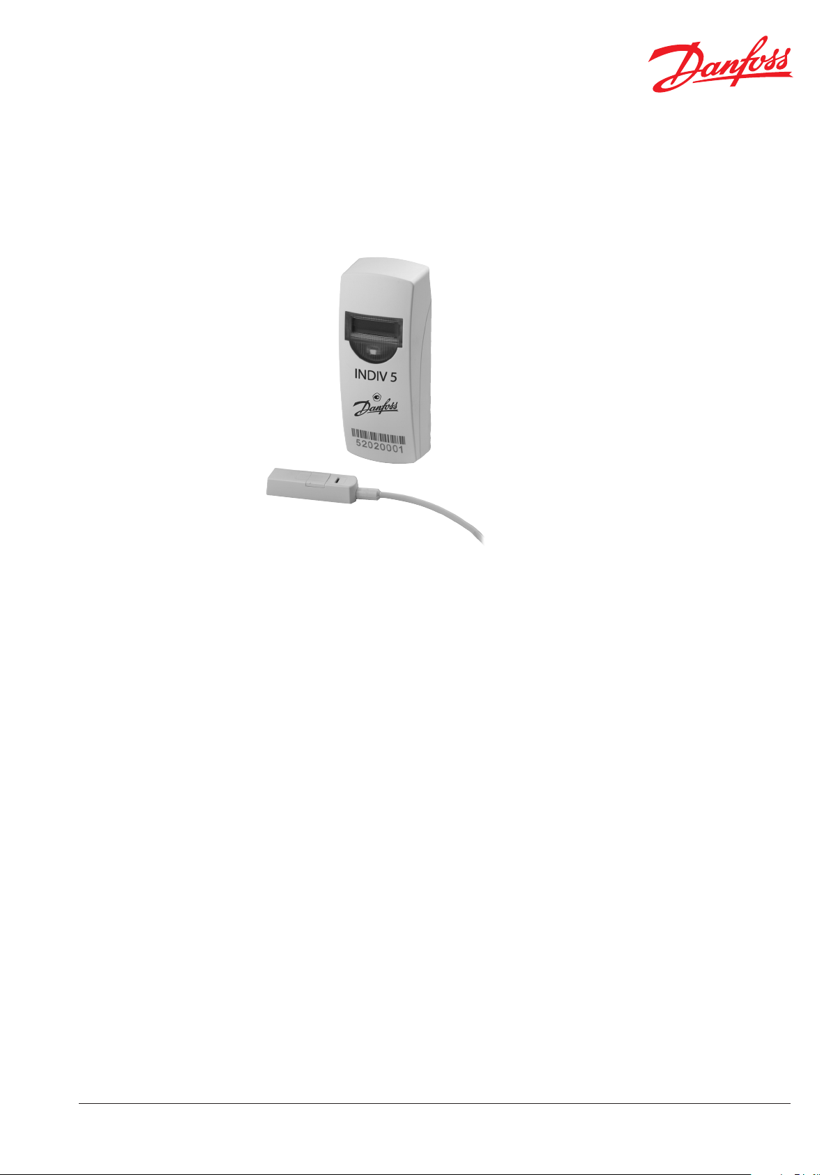
Electronic Heat Cost Allocator
INDIV-5
Application
The INDIV-5 is an electronic device for heat cost
allocation based on measuring the share of heat
output by radiators.
The INDIV-5 can be used in the system INDIV-5
basic or through an internal communication
interface in the system INDIV-5 AMR.
The INDIV-5 is available in versions with built-in
sensor and with remote sensor.
radiator temperature is determined in 2-sensor
mode, while a constant value is set for the
ambient temperature in 1-sensor mode.
The measured values are used for calculation of
the consumption.
The main area of application is in central heating
systems where the heating energy is used
individually by dierent consumers.
The electronic heat cost allocator can be
operated as a 1-sensor or 2-sensor measuring
system with product and unit scale.
Such systems are used in e.g. apartment buildings, oces and administration buildings.
Typical users are:
• Meter reading service companies
• Housing industry and housing associations
• Building service companies and property
management
The heat cost allocator can be used for the
following types of radiator:
• Ribbed radiators
• Tubular radiators
• Panel-type radiators with horizontal and
vertical water ow
• Radiators with internal tube register
• Convectors
Features
• Housing with pre-mounted lead factory seal
• Optional remote sensor (can be retrotted)
• Automatic identication of Remote Sensor
Mode
• AMR version with radio support
• Integrated detection of manipulation (e.g.
unauthorised opening of device)
• Saving of min. and max. temperatures
• Saving of duration of exception reporting
• Display error messages
• Display battery warning
• Measuring mode inactive in sleep mode
• Programmable individual settings
• No zeroing on due date - roller type counter
• History memory for 15 months
• Summer switch-o
INDIV-5 is designed for decentralised use. Values
are measured by one (radiator temperature) or
two (radiator and room air temperature) sensors.
The actual dierence between ambient and
Restrictions of use
Electronic heat cost allocators cannot be used
with steam heaters, fresh-air radiators, underoor
heating, ceiling heating elements or ap-controlled radiators.
In case of combined valve and ap-controlled
radiators, measuring devices may only be
installed if the ap control unit has been
removed or disabled in the “open” position.
Convectors that can change their output through
an electric blower and towel heaters with an electric heating cartridge must not be tted with
electronic heat cost allocators, unless the
respective electric system has been removed or
disabled.
For 1- and 2-sensor measuring system a joint use
of dierent measuring device types is only
allowed within a property as long as they all use a
standard measuring system and a uniform
measuring algorithm.
VDIGC102 © Danfoss 08/2013
1
Page 2
Data Sheet Electronic Heat Cost Allocator INDIV-5
Installation types
System modules
New installation
During new installation a property is equipped
completely with electronic heat cost allocators
for the rst time. No evaporators or other
metering devices have been used before.
Conversion installation
A billing unit is completely re-equipped with
electronic heat cost allocators.
The radiators were previously tted with meters
by other companies, which are removed
completely. The existing welding bolts are kept,
but the mounting plates are exchanged. Any
colour deviations at the radiator can be masked
by a snap-on panel with a neutral Kc-value.
INDIV-5 basic
The INDIV-5 basic system represents the entry
level to reliable consumer data recording. It
includes devices that can be readout visually.
INDIV-5 is especially suited for tasks or systems
that do not require complex data evaluations or
particularly fast readout processes.
The time needed for classical on-site meter
reading should be borne in mind when assessing
whether this system is suitable.
Measuring results are noted manually.
Extension installation
This installation expands a billing unit equipped
with Danfoss meters and additional meters, e.g.
due to installation of additional radiators.
Repair replacement
Individual meters will be exchanged against new
meters during a repair replacement. The reason
for the exchange can be a defect of the meter.
INDIV-5 AMR
Readouts of devices in the INDIV-5 AMR system
are radio-supported.
Data acquired by the meters are sent wirelessly to
stationary network nodes. Each network node
has all consumption information available on
account of continual data exchange between the
nodes. This data can be readout via the interface
at the node, by radio from a (stationary) vehicle
or via a gateway by modem or IP interface from a
remote location.
The devices transmit current consumption data in
cycles. The battery operated network nodes
receive, check and store all data automatically.
The data can now be read at any network node,
either directly through the data interface, “from
the outside” by radio or through a gateway from
the oce (e.g. through the GSM phone network
or broadband cable networks).
INDIV-5 AMR is compatible with the KNX
European standard for home automation.
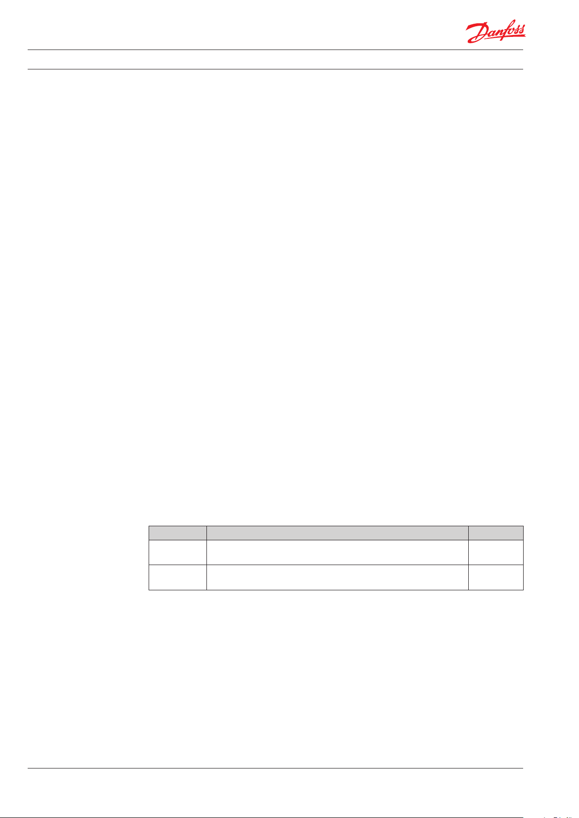
Ordering
2
Device Description Code no.
INDIV-5 basic
INDIV-5 AMR
Devices with other congurations are available on request. Please contact your local Danfoss sales
company for further information.
VDIGC102 © Danfoss 08/2013
1-sensor, battery warning on, summer switch-o between 06/01 and
08/31, due date 12/31
1-sensor, battery warning on, Summer switch-o between 06/01 and
08/31, due date 12/31
088H2330
088H2331
Page 3
Data Sheet Electronic Heat Cost Allocator INDIV-5
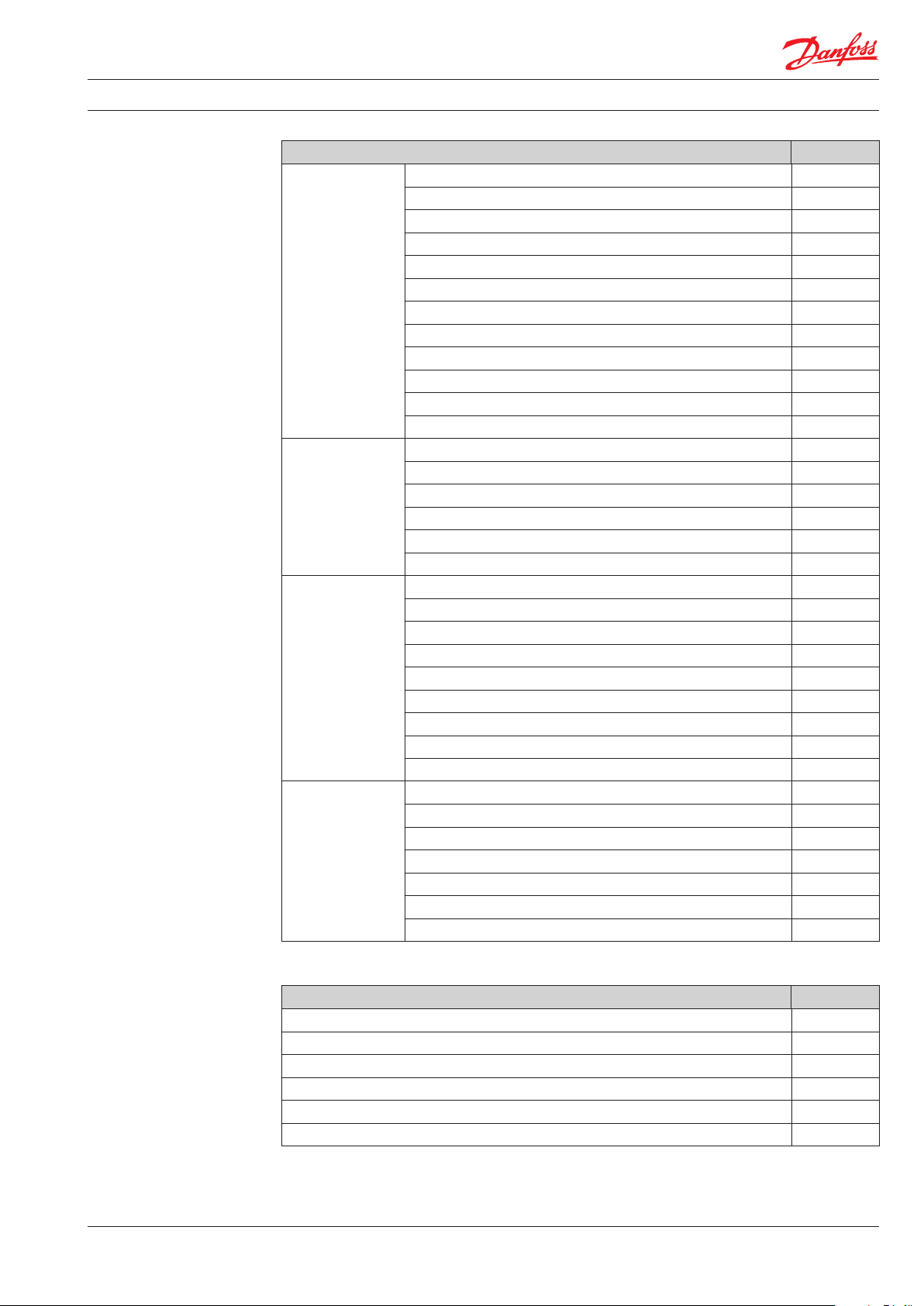
Accessories
Description Code no.
Threaded hoop (pipe 18 to 30 mm) 088H2320
Threaded hoop (pipe up to 17 mm) 088H2316
Shank nut M3 x 6 088H2226
Clamping bracket (pipes TE 36 mm) 088H2321
Clamping bracket (pipes TE 46 mm) 088H2322
Attachment Parts
Installation Parts
Standard Parts
Other Accessories
Clamping bracket shortened 088H2317
Clamping bracket trapezoidal 35 mm 088H2323
Clamping bracket trapezoidal 50 mm 088H2324
Clamping bracket trapezoidal 65 mm 088H2230
Square bolt 4.5 mm with cross pin 088H2311
Square bolt 6 mm with cross pin 088H2312
Square bolt 12 mm with cross pin 088H2313
Spacer 088H2240
Clamping piece (threaded hoop 17 mm) 088H2314
Clamping piece (threaded hoop 18 to 30 mm) 088H2315
Installation plate for remote sensor 088H2309
Installation plate standard 088H2211
Installation plate wide 088H2212
Self-tapping screw B 2.9 x 13 088H2247
Screw B 3.9 x 45 088H2327
Cross-slot screw M4 x 40 088H2233
Cross-slot screw M4 x 50 088H2325
Cross-slot screw M4 x 70 088H2326
Welded stud M3 x 8 088H2319
Welded stud M3 x 12 088H2222
Welded stud M3 x 15 088H2318
Self-locking nut with serrated bearing M3 088H2220
Dowel 6 mm 088H2328
ERGO superglue 088H2329
Lead seal blue 088H2299
Snap-on panel 088H2287
Installation template for holding against radiator 088H2285
Programming adapter 088H2341
Infrared read head with USB interface 088H2295
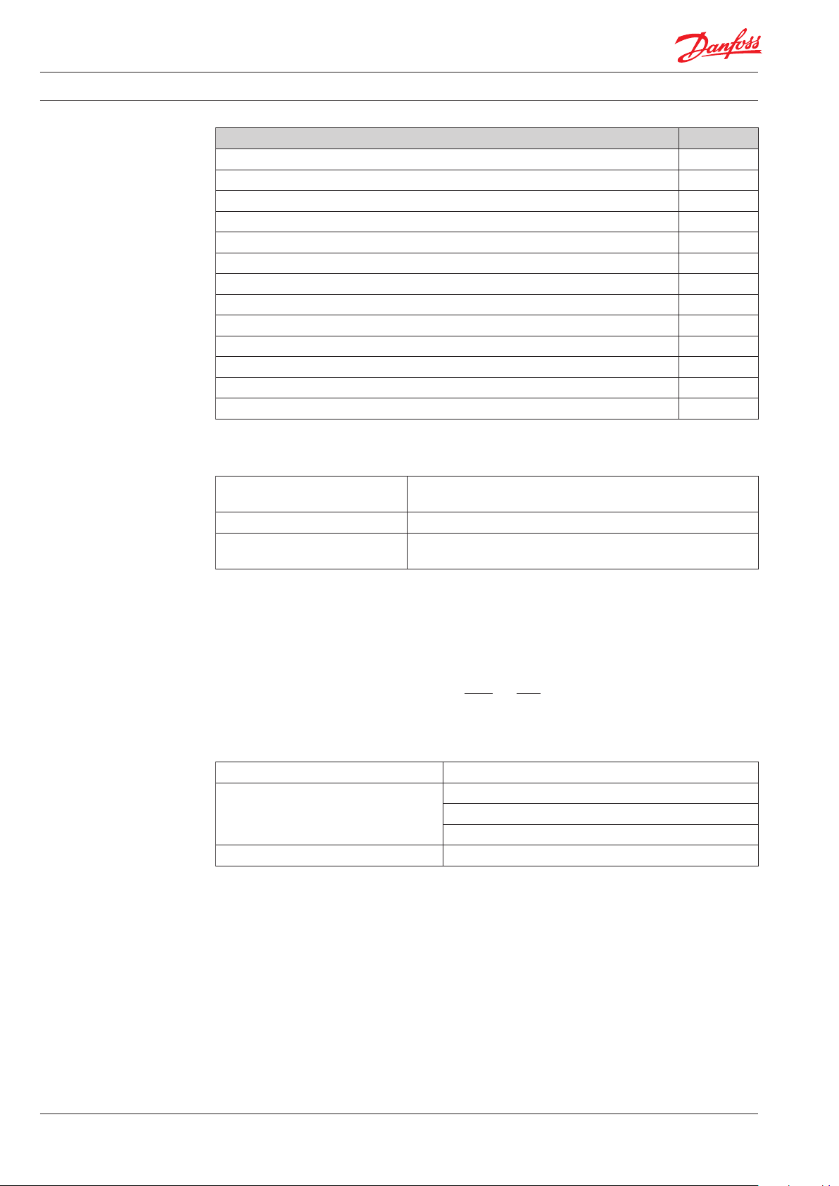
Radio system
components
Description Code no.
Pulse adapter Radio AMR 088H2338
Network node with battery, standard 088H2332
Gateway node, Ethernet 088H2335
PC-Radio modul 088H2337
Main battery for network node 088H2263
Back-up battery for Network node and Gateway 088H2264
VDIGC102 © Danfoss 08/2013
3
Page 4
Data Sheet Electronic Heat Cost Allocator INDIV-5
Installation sets for
remote sensors
Technology
Description Code no.
Wall bracket P3 088H2296
Remote sensor complete, 1.5 m 088H2297
Remote sensor complete, 2.5 m 088H2298
Remote sensor complete, 5.0 m 088H2310
Sensor attachment for ribbed radiator, division > 40 mm 088H2300
Sensor attachment for ribbed radiator, division = < 40 mm 088H2301
Sensor attachment for cast radiator type SR 088H2302
Sensor attachment for cast radiator type RR, KR 088H2303
Sensor attachment for panel radiator 088H2304
Sensor attachment for aluminum ribbed radiator 088H2305
Sensor attachment for ribbed convectors 088H2306
Sensor attachment for window ledge radiators 088H2307
Sensor attachment for prole radiators 088H2308
Standard Scale Operation*
Evaluation factor K
Evaluation factor K
= 1.28
CHFS
= 2.50 Standard for the 2-sensor measuring system
C2FS
Evaluation factor radiator
capacity KQS = 1000 W
* All metering devices in a system are programmed with the same evaluation factors.
Standard for the 1-sensor measuring system and for remote
sensor metering devices
Standard for the 1 and 2-sensor measuring system
Display correction with standard scaling
If the metering device has been operated with standard scaling, the displayed value (AW) must be
converted to the correct value (VW, billing value).
The basis for calculating consumption values, when Standard Scale is used, is the general equation:
VW = AW x
K
K
Q
QS
x
(Kc)
Kc
1.15
S
i.e. equations for calculating the consumption value:
Equation Applies to
Compact metering device, 1-sensor, (KcS = 1.28)
VW = AW × 7.529 × 10⁻⁴ × KQ × K
1.15
C
Remote sensor metering device, 1-sensor, (KcS = 1.28)
Remote sensor metering device, 2-sensor, (KcS = 1.28)
VW = AW × 3.486 × 10⁻⁴ × KQ × K
1.15
C
Compact metering device, 2-sensor¸ (KcS = 2.50)
The Kc value is given in the form of a Kc Value Database.
4
VDIGC102 © Danfoss 08/2013
Page 5

Data Sheet Electronic Heat Cost Allocator INDIV-5
Programming
accessories
Programming adapter
The programming adapter is used for communication with the devices. It can be used as an individual
programming tool or as a combination adapter with the IrDA programming and readout head.
A movable cover on the head
is used for protecting the
contact pins during transport.
IrDA programming and readout head*
The IrDA programming and readout head is used as a combination tool between a PC/Netbook and
the INDIV-5 device. The device can be programmed and read by using the Q suite 5 caloric.
Two rotary buttons at the rear
is used for programming.
During programming the
device is placed in a tray. An
acoustic signal tells you,
when the programming is
completed.
The programming adapter
has a exible protective
cover, which is used as a
storage compartment.
*Only required for meters without integrated close range interface.
When inserted in the adapter
the IrDA head will connect to
the PC/Netbook.
The device must be placed in
the tray during programming.
VDIGC102 © Danfoss 08/2013
5
Page 6

Data Sheet Electronic Heat Cost Allocator INDIV-5
S
S
Display loops,
Normal Mode
Equipment conditions, consumption values and metering system information are displayed on the LC
display through a display loop.
Current consumption
Display test:
2 S
0.5
Everything on
Display test:
0.5
Everything o
Due date
e.g. 31st December
Due date value
(ashing)
Checksum
Validation level
K level
2 S
5 S
2 S
1 S
Variable display
“Fa” : Code for the AMR radio system
XX
“aL” : Algorithm, no radio system available
“3” : Code for the WHE3x algorithm
Y
“4” : Code for the WHE4x algorithm
“1” : Code for the 1-sensor measuring system
Z
“2” : Code for the 2-sensor measuring system
XX YZ
1 S
6
VDIGC102 © Danfoss 08/2013
Page 7

Data Sheet Electronic Heat Cost Allocator INDIV-5
S
S
S
S
Plain text
S
discrete
S
S
S
S
Display loops,
Sleep Mode
The meters are delivered from the factory in sleep mode. The metering mode is inactive.
Sleep mode
Measuring operation inactive
Due date
e.g. 31st December
“Fa” : Code for the AMR radio system
XX
Variable display
XX YZ
“ a” : Code for an active AMR radio system
“aL” : Algorithm, no radio system available
“3” : Code for the WHE3x algorithm
Y
“4” : Code for the WHE4x algorithm
2
2
2
Special displays
“1” : Code for the 1-sensor measuring system
Z
“2” : Code for the 2-sensor measuring system
Error messages
“Err 1” appears permanently. All other error messages are displayed
in a fast sequence alternating with the consumption values.
Consumption display suppressed
Is displayed in case of an error after programming instead of the
invalid consumption values.
End of battery run time
Depending on programming, will be displayed alternating with the
consumption values after the operating time expired.
Manipulation or housing opening
Will be displayed - in case of manipulation and depending on
programming - either as plain text alternating with the consumption values or by the indicator “c” discretely on all displays.
Example: Display “current value” with “c”.
Data interface (Close range interface)
This display signalises an active close-range interface.
Radio system activated (AMR)
The transmission of installation telegrams is indicated on this
display. Display sequence: InSt8, InSt7, ... InSt1.
Commissioning
This display appears following latching-on to the mounting plate.
Then the display changes to the display loop of the normal mode.
Remote sensor identication
The meter has detected a remote sensor and adjusts its measuring
behaviour accordingly.
0.5 S
0.5 S
0.5 S
0.5
0.5
10
30
3
3
alt.
alt.
alt.
VDIGC102 © Danfoss 08/2013
7
Page 8

Data Sheet Electronic Heat Cost Allocator INDIV-5
Available data
Device number The device number is laser printed, both as an 8-digit code and as a bar code
on the front of the device.
Display The display alternates between the following information:
• Current consumption
• Due date value
• Due date
• Checksum
• Algorithm and sensor system
• Data interface active
· · ·
• Sleep mode
• Error messages
• End of battery run time
• Manipulation or housing opening
• Installation telegram
· · ·
Programming
possibilities
The following information can be programmed before the measuring device
is put into operation:
Standard parameters
• Sensor type: 1-sensor or 2-sensor measuring system
• KC / KQ: Evaluation factors for the calculation of the heat output of a
radiator (depending on the meter algorithm and the sensor type)
• Next due date: Day on which the annual value is stored
• Equipment name/equipment code: Equipment access data to prevent
unauthorised equipment access
Special functions
• Continuous counting (without zeroing): The meter count will not be set to
zero at the due date, but continues to count similar to a roller type counter.
The annual value will be calculated based on the dierence between the
new and the old meter count. As a default, this options is set to “no” (meter
count will be reset to “0” at the due date).
• Display battery warning: The HCA includes runtime monitoring. “bat00”
will be displayed on the HCA display as an optical information that the
battery service life has expired. As a default, this option will be set to “no”
(no display of the battery warning).
• Display meter readings in case of errors: The HCA display shows the units
accumulated until the failure of the HCA as the meter count. As a default,
this option will be set to “no”, i.e. “----” will be displayed on the HCA display
if the consumption values are unusable for a billing due to an equipment
error.
• Start display as plain text: An identied housing opening will be displayed
as a plain text message on the HCA display as “c OPEn” alternating with the
current value or the value of the previous year (old value). An identied
housing opening can be identied by the display of the icon “c” on all
displays (discrete display) if this option is set to “no”.
8
VDIGC102 © Danfoss 08/2013
Page 9

Data Sheet Electronic Heat Cost Allocator INDIV-5
Technical features
Function control The measuring device carries a self-test out every 4 minutes. An error message
“Err x” will be displayed if an error occurred during ve consecutive metering
cycles (20 minutes).
After the error has been registered and shown on the display, the measuring
device stops the measuring operation. The data of the error occurrence is
stored internally.
Radio system Uni-directional radio 868.95 MHz according to current specication for AMR.
Useful data content of the AMR telegrams:
• Device number (8-digit)
• Device type/software version
• T ime/date
• Error status
• Error date
• Current consumption
• Due date
• Due date value
• Counter status at end of last month
VDIGC102 © Danfoss 08/2013
9
Page 10

Data Sheet Electronic Heat Cost Allocator INDIV-5
Technical data
Measuring system
Device versions
1-sensor with dynamic heating operating detection
2-sensor, for radiator and for room temperature
Compact device
Remote sensor device (compact device with inserted remote sensor)
Power supply 3 V lithium battery, typical lifetime 10 years
Display Liquid Crystal display (LCD) with 5 digits (00000 ... 99999)
Evaluation
Radiator power
range
Sensor temperature
range
1-sensor: 255 levels
2-sensor: 999 levels
21 - 9,999 W
0 to 105°C
tm-max: 105°C
tm-min: 35°C (2-sensor), 55°C (1-sensor)
Temperature sensor NTC, prematurely aged
Frequency: 868,95 MHz with 1% duty cycle
Radio
Transmission power: 0 dB1) (typical 3dBm)
Protocol: Wireless M-Bus acc. to EN13757-4
1- or 2-sensor
Measuring
principle
1-sensor INDIV-5
algorithm
Area of application
2)
2-sensor INDIV-5
algorithm
Standard scale
Scaled
2-sensor INDIV-5
algorithm
tz ≥ 30°C (at tL = 20°C) non-evaluated
tz ≥ 28°C (at tL = 20°C) evaluated
Start of metering
1-sensor device
t
min,m
t
max,m
t
min,m
t
max,m
t
min,m
t
max,m
t
min,m
t
max,m
= 55°C
= 105°C
= 48°C
= 105°C
= 35°C
= 105°C
= 35°C
= 105°C
2-sensor device tz - tL ≤ 5 K
Protection data
Ambient conditions
Protection class III acc. to EN61140
Protective rating for housing IP32 acc. to EN60529
Operation
EN60721-3-3
Transport
EN60721-3-2
Storage
EN60721-3-1
Climatic con. 3K4 2K3 1K3
Temperature 5...70 °C -25...70 °C -5...45 °C
Humidity <95% rel.
Mechanical con. 3M2 2M2 1M2
2004/108/EC
EN 61000-6-2, EN 61000-6-3
2006/95/EC
EN 60 95 0-1
1999/5/EC
EN 300 220-2
EN834
ISO 14001 (environment)
ISO 9001 (quality)
GL 2002/95/EC (RoHS)
Directive (EC) 1907/2006 (REACH)
Norms and
standards
Environmental
compatibility
CE Conformity according to EMC guideline
- Interference resistance, emissions
Low-voltage guideline - Electrical safety
RTTE (Radio & Telecom. Equipment) - Radio
communication
Heat cost allocator for acquiring consumption data for room heating
Product environment declaration
CE2E2886de contains data about environmentally friendly product design and
evaluation (RoHS conformity, substances
used, packaging, environmental benets,
disposal)
Dimensions W x H x D: 40 x 102 x 31 mm
Weight 58 g (device packed with attachments)
Remote sensor cable Length: 150, 250 or 500 cm
Housing
1)
In connection with an AMR network node, a horizontal range of around 15 m and a vertical range of around 1 oor up
Material PC- AB S
Colour RAL 9016 (Trac White)
or down are achieved in a t ypical building. The PC radio module (088H2337) is available for exact range calculation.
The range specication is purely informative and does not represent any guaranteed system parameters.
2)
Denitions according to EN 834:
t
Lowest mean design heating medium temperature at which the heat cost allocator may be used. With
min,m
single-tube heating systems this is the mean design heating medium temperature of the last radiator in the
strand.
t
Highest mean design heating medium temperature at which the heat cost allocator may be used.
max,m
tzMean heating medium temperature of the radiator at which the counter of the heat cost allocator starts up.
tLReference air temperature.
tmMean heating medium temperature.
10
VDIGC102 © Danfoss 08/2013
Page 11

Data Sheet Electronic Heat Cost Allocator INDIV-5
102
30
40
11.5
76.3 91.3
Dimensions
32
60.3
44.8
40.9525.95
INDIV-5 device Snap-on panel
VDIGC102 © Danfoss 08/2013
11
Page 12

Data Sheet Electronic Heat Cost Allocator INDIV-5
12
VDIGC102 © Danfoss 08/2013
 Loading...