

Page 1
Data sheet
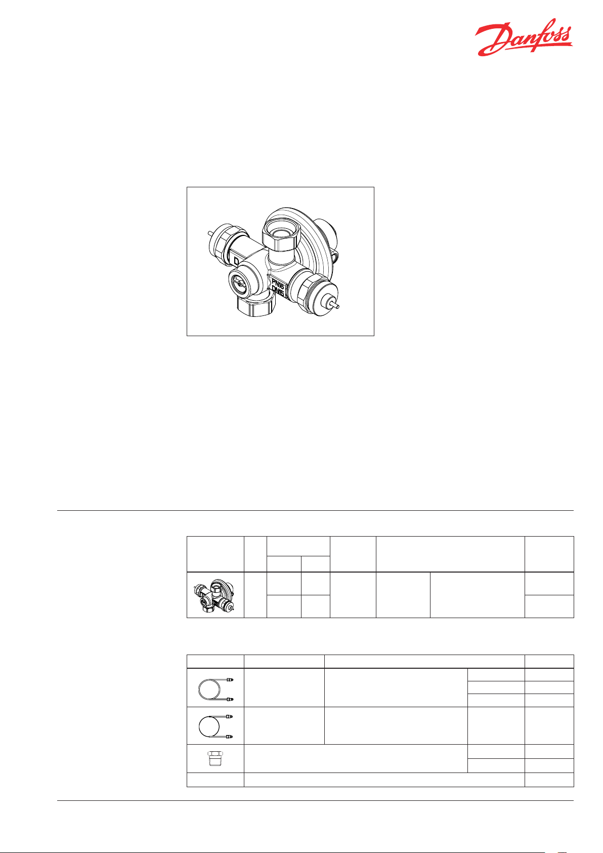
Integrated controller with two control valves and diff. pressure controller (PN 16)
IHPMM-F – flow mounting, fixed differential pressure setting
Description
IHPMM-F is an integrated controller which
consist of two control valves and one self-acting
differential pressure controller. It is developed
primarily for use in district heating systems. The
differential pressure controller closes on rising
differential pressure.
Two control valves are developed to control
heating circuit (HE) and domestic hot water
(DHW) production.
There are other possibilities to use controllers as
well:
- to use both control valves for heating
- to use both control valves for domestic hot
water production
In combination with Danfoss electrical actuators
AMV(E) can be controlled by ECL electronic
controllers.
Innovative compact design enables space
saving due to reduction of number components
and simple, fast and reliable mounting into
substation.
Control valves are used together with Danfoss
electrical actuators:
- AMV(E) 150
- AMV(E) 10 / AMV(E) 20 / AMV(E) 30
- AMV(E) 13 / AMV(E) 23 / AMV(E) 33 with spring
return function
- AMV 20SL / AMV 23SL / AMV 30SL with stroke
limitation
Main data:
• DN 15
• kVS values:
Heating 0.25 m3/h, DHW 1.6 m3/h /
Heating 0.63 m3/h, DHW 2.5 m3/h
• PN 16
• Fixed p setting range: 0.8 bar
• Temperature:
- Circulation water / glycolic water up to 30%:
2 … 150 °C
• Connections:
- Ext. thread (inlet) and int. thread (outlet)
Description
Example:
Integrated controller with two
control valves and differential
pressure controller, DN 15,
kVS HE 0.25, kVS DHW 1.6, PN 16,
fixed ∆p setting 0.8 bar, t
thread
- 1× IHPMM-F DN 15 controller
Code No: 003L354 0
Option:
- 1× Impulse tube set AH, 1.5 m
Code No: 003L8152
- 1× Nipple for imp. tube
Code No: 003L5042
External impulse tube (AH), nipple
for impulse tube and electrical
actuators AMV(E) must be ordered
separately.
DH-SMT/SI VD.LR.C 3.02 © Danfoss 06/2010 1
FOR INTERNAL USE ONLY
max
150 °C,
IHPMM-F Controller
k
Picture DN
1)
I-pack 24 pcs .
VS Δp setting
HE DHW
0.25 1.6
15
0.63 2.5 003L3541
range
(bar)
0.8
Cylindrical
thread acc. to
ISO 228/1
Connection Code No.
Inlet ext. thread G / A
outlet int. thread (nut)
G / A
Accessories
Picture Type designation Connection Code No.
Description:
Impulse tube set AH
Impulse tube set
AH for pressure
reduction
Nipple for impulse tube connection to pipe
10 EPDM o-rings for impulse tube 003L8175
- 1× copper tube Ø 3 × 1 mm
- 2× fitting for imp. tube connection
to actuator and pipe R /
Description:
- 1× stainless steel tube Ø 0.8 × 0.2 mm
- 2× fitting for imp. tube connection
to actuator and pipe R /
1.5 m 003L8152
2.5 m 003L5043
5 m 003L8153
0.8 m 003L3650
G / - R / 003L5042
G / - R / 003L8151
003L3540
1)
1)
Page 2
Data sheet
Integrated controller with two control valves and diff. press. controller IHPMM-F
(PN 16)
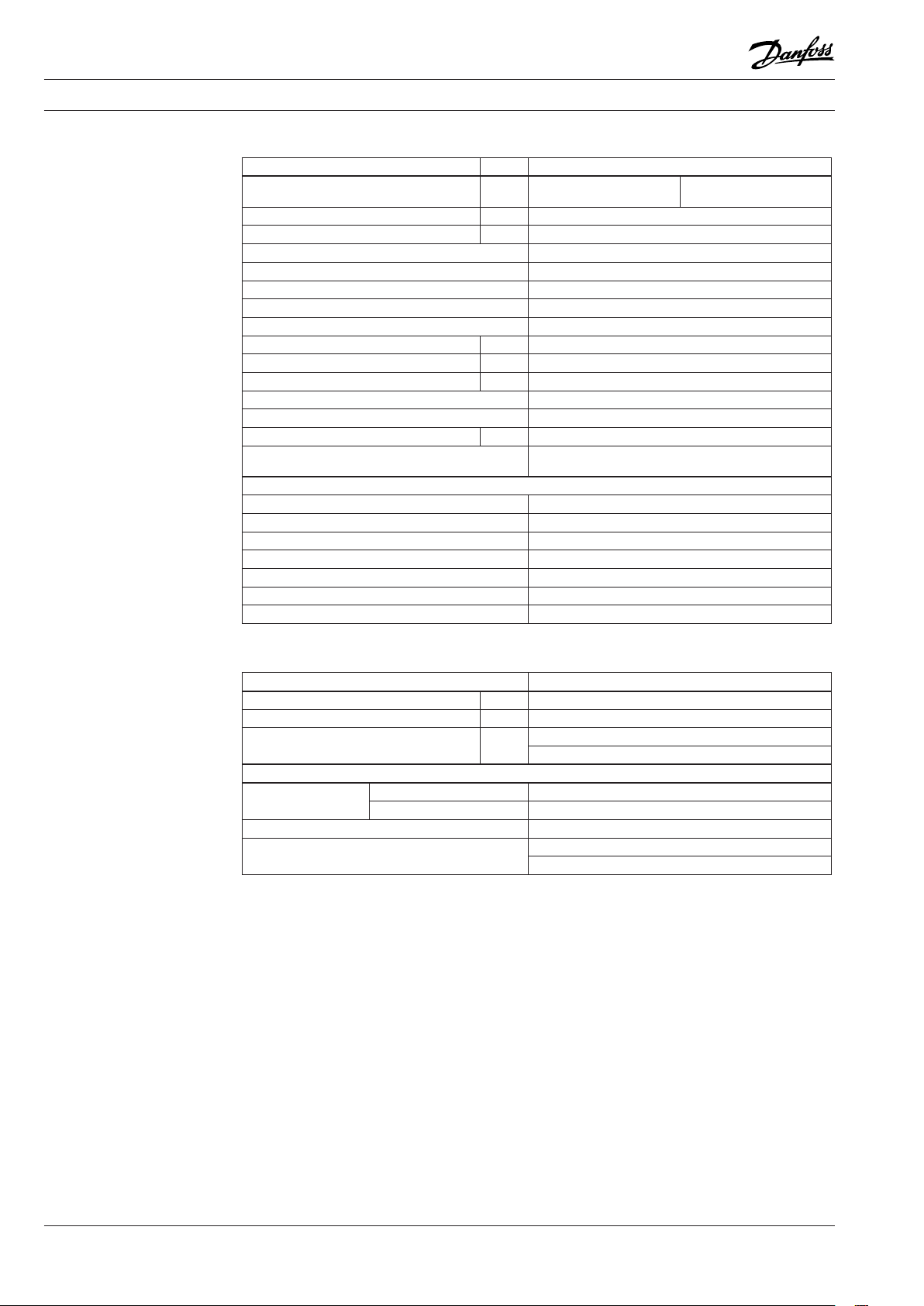
Technical data
Valve*
Nominal diameter DN 15
kVS value HE
DHW
kVS value DP m3/h 4.0
Stroke HE, DHW mm 5
Control ratio HE > 1:30
Control ratio DHW > 1:50
Control characteristic HE, DHW Split characteristics
Cavitation factor z ≥ 0.5
Leakage acc. to standard IEC 534 0.05
Nominal pressure PN 16
Max. differential pressure bar 10
Max. closing pressure HE, DHW bar 10
Medium Circulation water / glycolic water up to 30%
Medium pH Min. 7, max. 10
Medium temperature ºC 2 … 150
Connections
Materials
Valve body Dezincing free brass CuZn36Pb2As
Valve seat DP Stainless steel, mat. No. 1.4404 NC
Valve seat HE, DHW Dezincing free brass CuZn36Pb2As
Valve cone DP Dezincing free brass CuZn36Pb2As
Valve cone HE, DHW Dezincing free brass CuZn36Pb2As
Sealing DP EPDM
Sealing HE, DHW Metal
* HE - heating valve , DHW - domestic hot water valve, DP - d iff. p ressure controller
m3/h
0.25
1.6
Inlet ext. thread G / A
outlet int. thread (nut) G / A
0.63
2.5
Actuator
Type IHPMM-F
Actuator size cm
Nominal pressure PN 16
Diff. pressure setting range bar
Materials
Actuator housing
Diaphragm EPDM
Impulse tube
Upper casing of diaphragm Dezincing free brass CuZn36Pb2As
Lower casing of diaphragm Brass CuZn40Pb2
2
Copper tube Ø 3 × 1 mm
Stainless steel tube Ø 0.8 × 0.2 × 800 mm
20.5
0.8
(fixed setting)
FOR INTERNAL USE ONLY
2 VD.LR.C 3.02 © Danfoss 06/2010 DH-SMT/SI
Page 3
Data sheet
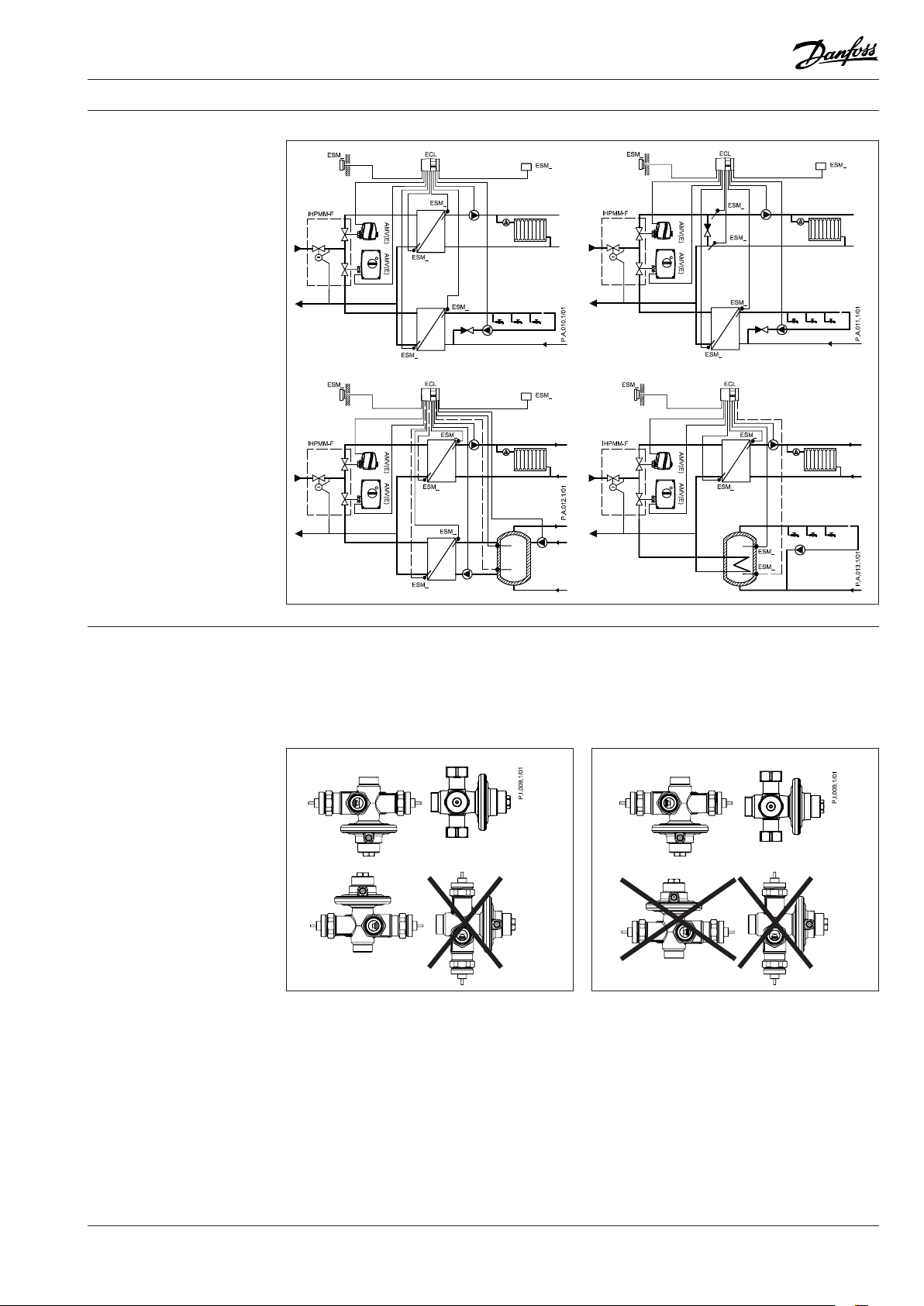
Application principles
Integrated controller with two control valves and diff. press. controller IHPMM-F
(PN 16)
Installation positions
FOR INTERNAL USE ONLY
Up to medium temperature of 100 °C the
controllers can be installed in any position,
except with (connection neck for) electrical
actuator oriented downwards.
Electrical actuator
Note!
Installation positions for electrical actuator
AMV(E) have to be observed as well. Please see
relevant Data Sheet.
For higher temperatures the controllers can
be installed with differential pressure actuator
oriented downwards or horizontal, except with
(connection neck for) electrical actuator oriented
downwards.
DH-SMT/SI VD.LR.C 3.02 © Danfoss 06/2010 3
Page 4

Data sheet
Pressure temperature
diagram
Design
1. Valve body
2. Pressure relieved valve seat *
- DP controller
3. Valve cone * - DP controller
4. Valve steam - DP controller
5. Differential pressure actuator
6. Upper casing of diaphragm
7. Lower casing of diaphragm
8. Control diaphragm
9. Spring for DP control
10. Safety valve
11. Pressure connection (G /)
12. Control valve insert - Heating
13. Control valve cone - Heating
14. Control valve inser t -
Domestic hot water
15. Control valve cone - Domestic
hot water
16. Leakage protective cover
17. Connecting nut (G /)
* Differential p ressure controller has
fixed cone and mov ing seat
Integrated controller with two control valves and diff. press. controller IHPMM-F
CuZn36Pb2As (DZR) PN 16
working
area
Maximum allowed operating pressure as a function of medium temperature (according to EN 1092-3).
(PN 16)
Function
FOR INTERNAL USE ONLY
4 VD.LR.C 3.02 © Danfoss 06/2010 DH-SMT/SI
Temperature control
Medium temperatures on heating and domestic
hot water secondary sides are being controlled
by electronic controller (wheather compensator).
Electronic controller based on it’s algorithm
adequately, via electrical actuators, opens or
closes both valves.
Differential pressure control
Pressure changes from the flow and return
pipeline are being transferred through the
impulse tube and control drain in the actuator
stem to the actuator chambers and act on
control diaphragm. Control valve closes on
rising differential pressure and opens on falling
differential pressure to maintain constant
differential pressure.
Page 5

Data sheet
Dimensions
Integrated controller with two control valves and diff. press. controller IHPMM-F
Nipples
(PN 16)
FOR INTERNAL USE ONLY
DH-SMT/SI VD.LR.C 3.02 © Danfoss 06/2010 5
Page 6

Data sheet
Integrated controller with two control valves and diff. press. controller IHPMM-F
(PN 16)
FOR INTERNAL USE ONLY
6 VD.LR.C 3.02 © Danfoss 06/2010 DH-SMT/SI
Page 7

Data sheet
Integrated controller with two control valves and diff. press. controller IHPMM-F
(PN 16)
FOR INTERNAL USE ONLY
DH-SMT/SI VD.LR.C 3.02 © Danfoss 06/2010 7
Page 8

Data sheet
Integrated controller with two control valves and diff. press. controller IHPMM-F
(PN 16)
FOR INTERNAL USE ONLY
8
VD.LR.C3.02
Produce d by Danfoss A/S © 06/ 2010
 Loading...