

Page 1
Installation and Instruction
PLRCA.PI.BX0.A1.02 / 520H3005
© Danfoss Saginomiya
取 扱 説 明 書
Checked by drawn by date Name Catalog Number Drawing Number
MAY.2001 IEV A-EV-46002
SSSSoooolllleeeennnnooooiiiidddd VVVVaaaallllvvvveeee
FFFFoooorrrr RRRReeeeffffrrrriiiiggggeeeerrrraaaannnntttt
AAAA.... FFFFaaaaiiiilllluuuurrrreeee ttttoooo rrrreeeeaaaadddd aaaannnndddd ffffoooolllllllloooowwww aaaallllllll iiiinnnnssssttttrrrruuuuccccttttiiiioooonnnn ccccaaaarrrreeeeffffuuuullllllllyyyy bbbbeeeeffffoooorrrreeee iiiinnnnssssttttaaaalllllllliiiinnnngggg oooorrrr
ooooppppeeeerrrraaaattttiiiinnnngggg tttthhhhiiiissss ssssoooolllleeeennnnooooiiiidddd vvvvaaaallllvvvveeee ccccoooouuuulllldddd ccccaaaauuuusssseeee ppppeeeerrrrssssoooonnnnaaaallll iiiinnnnjjjjuuuurrrryyyy aaaannnndddd////oooorrrr pppprrrrooooppppeeeerrrrttttyyyy
ddddaaaammmmaaaaggggeeee.... SSSSaaaavvvveeee tttthhhheeeesssseeee iiiinnnnssssttttrrrruuuuccccttttiiiioooonnnnssss ffffoooorrrr ffffuuuuttttuuuurrrreeee uuuusssseeee....
BBBB NNNNOOOOTTTTEEEE FFFFOOOORRRR SSSSAAAAFFFFEEEETTTTYYYY
WWWWaaaarrrrnnnniiiinnnngggg
When removing the solenoid coil from the valve body, be sure to cut out the power supply as the coil
may burn.
Do not apply the different voltage from the voltage marked on the coil label.
It may cause burning or failure.
While power is on, do not touch the housing cover as personal injury may be caused.
(Coil heats up to 90℃)
Do not apply excessive force and/or any impact to the coil as it may cause valve failure, burn-out
and leakage trouble due to deformation.
Do not heat up the solenoid coil as the coil might be burn-out.
Do not put any inflammable thing around the coil as it could catch fire due to the coil heat.
CCCC SSSSPPPPEEEECCCCIIIIFFFFIIIICCCCAAAATTTTIIIIOOOONNNNSSSS
Min Bursting Press. 4.41 MPa{45/} Airtight Pressure 2.94 MPa{30/}
Max Working Press. 2.94 MPa{30/}
Max Operating Press. Diff. 2.06 MPa{21/}〔IEV-B1505DX,B2007DX=2.25MPa {23/}〕
Min Operating Press. Diff. 0.29 MPa{3/}〔IEV-B1505DX,B2007DX=0.49MPa {5/}〕
Max(Min) operating pressure diff. is pressure difference between discharge pressure and suction pressure of comprossor.
Fluid Viscosity 50/s
Ambient Humidity 95%RH or less
Fluid Temp. -20 to +125℃{IEV-B1505DX,B2007DX=-20~+120℃}
Kind Of IEV
F o r D i s t r i b u t i n g C i r c u i t ( I E V - T y p e B ) F o r C h a n g e o v e r C i r c u i t ( I E V - T y p e C )
Energized(ON) Energized(ON)
A → C
De-Energized(OFF) De-Energized(OFF)
A → B
As explained in NOTE For SAFETY, coil may burn out at an abnormal condition. Use a suitable fuse.
The Coil For IEV-B1505DX,IEV-B2007DX With The Thermal Cutoff Fuse Is Available Upon Request.
DDDD EEEELLLLEEEECCCCTTTTRRRRIIIICCCCAAAALLLL CCCCHHHHAAAARRRRAAAACCCCTTTTEEEERRRRIIIISSSSTTTTIIIICCCCSSSS
B1 505DX
B2 007DX
B3 2**DX
C3 2**DX
EEEE IIIINNNNSSSSTTTTAAAALLLLLLLLAAAATTTTIIIIOOOONNNN
<Before Installation>
Confirm the supply voltage to conform with the voltage marked at the coil
label on the housing cover.
Be careful to select a refigerant oil if viscosity of the oil exceeds 50/s
as it might cause failure of solenoid valve.
As for the following specification,there is a case different from indication of a product.
Fluid FLUORO CARBON
Coil insulation Class B molded
Ambient Temp. -20 to +50℃
A C
B
Rated Voltage/FrequencyType IEV-
100V 50/60Hz
110V 60Hz
200V 50/60Hz
220V 60Hz
100V 50/60Hz
110V 60Hz
200V 50/60Hz
220V 60Hz
A:Compressor Discharge Line
B:Condenser Inlet Line
D
C:Sub-Condenser Inlet Line
(Or Evaporator Inlet Line)
D:Compressor Suction Line
110/90 mA
100 mA
55/45 mA
50 mA
170/140 mA
150 mA
85/70 mA
75 mA
B → A
A → C
WattageRunning Current Coils
6/5 W
6 W
6/5 W
6 W
8/7 W
8 W
8/7 W
8 W
A C
AC100V coil
AC200V coil 0.2A
AC100V coil
AC200V coil
B
A:Evaporator Outlet Line
D
B:Compressor Discharge Line
C:Compressor Suction Line
D:Compressor Suction Line
Proper Current Fuse
0.5A
0.5A
0.3A
Note : SI unit {Metric unit}
Do not carry the valve with holding the lead wire only as it may
cause coil burn-out.
Be careful to scratch flared part and/or brazing point as it might
cause leakage trouble.
Remove any foreign material or dust in the pipe as it may cause failure of
the solenoid valve.
Use a mesh strainer (80 to 100 mesh)at the valve inlet.
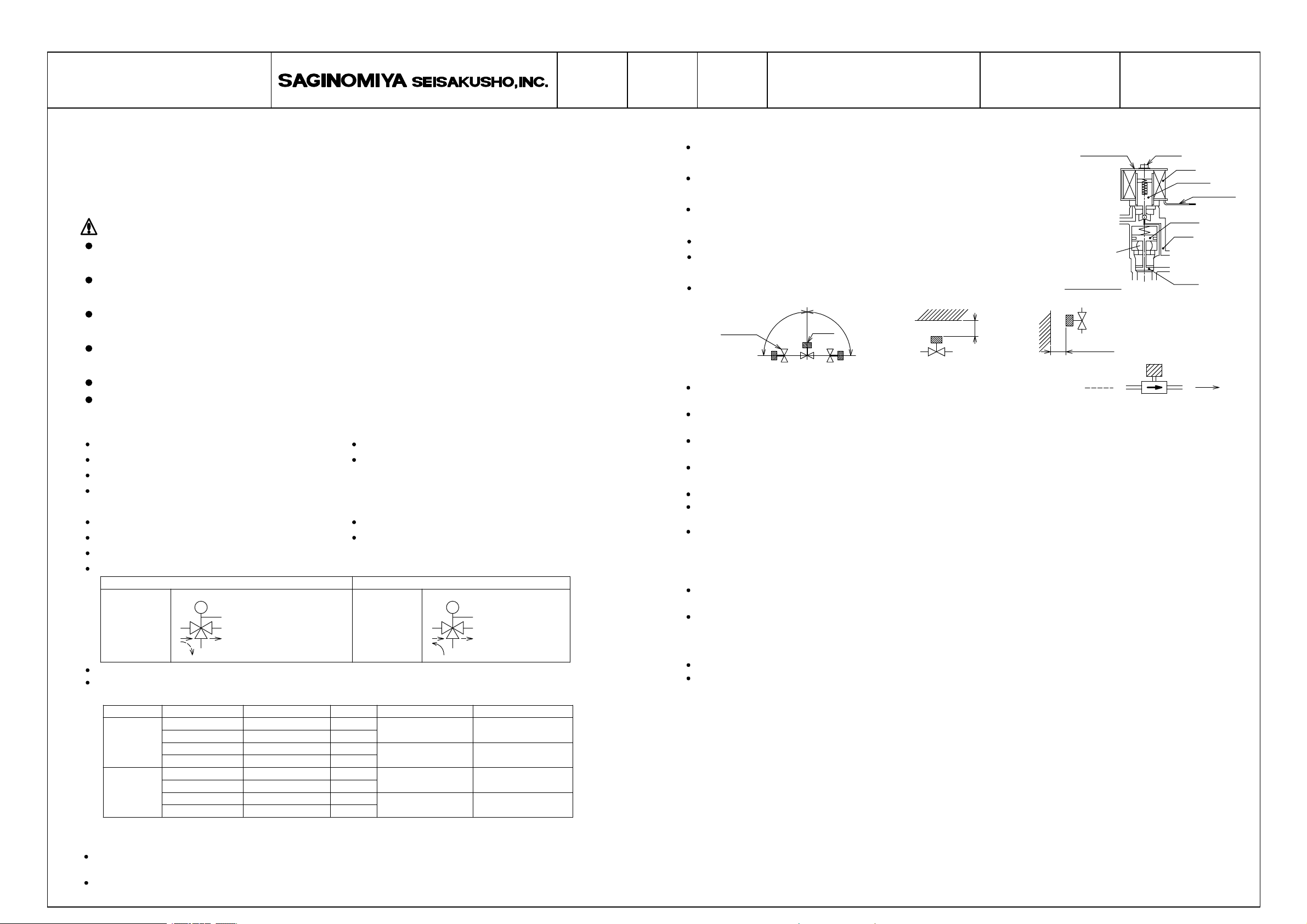
Mounting position should be in the following range.
(The coil should always direct upward or horizontal.)
Grounding is required at a suitable position on the unit.
゚
Valve Body
<Installation>
When installing the solenoid valve, be sure the arrow embossed on the valve body
points the direction of refrigerant flow.(Be sure to correctly locate outlet and inlet side.)
Special attention is required not to apply back pressure. Inner parts of valve may be deformed and
may cause leakage trouble.
Do not install a check valve at the inlet side as it may cause liquid sealing condition on the pipe inside and
may cause damage due to excessive pressure.
When brazing the joints, the valve body should be kept cool by wet rags in order not to heat up the valve body in
excess of 120℃(Do not direct the flame to the valve body.)
When brazing, valve inside should be filled with inactive gas(N or CO )to prevent generation of scale.
Special attention is required not to apply excessive force of compression, tension or torsion against the
valve body as it may cause malfunction.
After putting the solenoid coil to the valve body and/or changing the coil direction, be sure to
tighten the screw firmly.
Proper tightening torque : 3N・m{30・cm}〔IEV-B1505DX,B2007DX=2N・m{20・㎝}〕
<Operation>
When removing the solenoid coil from the valve body, be sure to cut out the power supply as the coil
may burn.
Before removing the solenoid coil from the valve body, be sure to cut the power supply. If energizing the coil
itself while it is not assembled into the valve body, the coil may cause burn-out.
90
Coil
90゚
Min 50㎜
2
2
IEV-Type B
Min 50㎜
D
C
ScrewCoil Cover
Piston
Body
B
FFFF MMMMAAAAIIIINNNNTTTTEEEENNNNAAAANNNNCCCCEEEE////IIIINNNNSSSSPPPPEEEECCCCTTTTIIIIOOOONNNN
In case of disassembling or inspection, please contact Saginomiya.
Before making a maintenance or inspection for the valve, be sure to cut the power supply.
GGGG OOOOPPPPEEEERRRRAAAATTTTIIIIOOOONNNN CCCCHHHHEEEECCCCKKKK
Install the Product correctly and then check its operation to confirm collect function of the whole system.
HHHH LLLLIIIIMMMMIIIITTTT OOOONNNN AAAAPPPPPPPPLLLLIIIICCCCAAAATTTTIIIIOOOONNNN
The product is not designed and manufactured for such equipment or system that is intended to be used
under such circumstances as to relate to human life. For application requieing specially high reliability,
please contact Company first.
IIII SSSSCCCCOOOOPPPPEEEE OOOOFFFF WWWWAAAARRRRRRRRAAAANNNNTTTTYYYY
Unless otherwise agreed by the parties, warranty period of the Product shall be one year after delivery.
In case of failure attributable to the Company within such period, the Product shall be repaired or repaired or
replaced, provided that any one of followings are out of the warranty :
1.Improper handling or application by user
2.Modification or repair by other than the Company
3.Any failure to be caused by acts of God, fire, storm or the like, war,riot or the like and other causes beyond
the control of the parties concerned.
Warranty described in this paragraph means the warranty for the Product itself and does not include warranty for
any consequential damage arising out of or occasioned by a defect or failure of the Product.
Coil
Plunger
Lead Wire
A
Valve
 Loading...