

Page 1
Data Sheet
Pilot operated servo valve
Type ICSH 25-80
2 step opening of hot gas lines for defrosting
ICSH dual position solenoid valve belongs to
the ICV family and consists of an ICV housing,
an ICS insert together with an ICSH top cover
with 2 EVM normally closed solenoid pilots
installed in the top cover.
ICSH is used in hot gas lines for the opening of
hot gas defrost ow to the evaporator in 2
steps. Both steps are activated by a controller or
a PLC energizing the magnetic coils in a time
delay sequence.
Step 1 (approx. 20% of full ow) is to allow a
smooth pressure build-up in the evaporator,
while the subsequent step 2 opens the ow to
100% to get the full defrost capacity.
The ICSH is designed for large industrial
refrigeration systems with ammonia,
uorinated refrigerants or CO2.
The ICSH features 2 conguration options,
which is established at site.
First option is dependent conguration, which
secures that step 2 can never open unless step
1 has been mechanically activated.
Second option is independent conguration
that allows step 2 to open disregarding step 1.
By choosing the independent option attention
should be paid to the risk of liquid hammering
in case the step 1 for any reason is disregarded.
AI260929867804en-000501
Page 2

Pilot operated servo valve, type ICSH 25-80
Features
• Designed for Industrial Refrigeration applications for a maximum working pressure of 52 bar / 754 psig.
• Applicable to HCFC, HFC, R717 (Ammonia) and R744 (CO2).
• Direct welded connections.
• Connection types include butt weld, socket weld and solder connections.
• Low temperature steel body.
• Low weight and compact design.
• 2-wire connection for use with a timer relay or 4 wire connection for connecting to a controller or a PLC.
• The ICSH main valve top cover can be oriented in any direction without the function of pilot valves being aected.
• Stabilizes working conditions and eliminates pressure pulsations during opening of hot gas.
• Manual opening possible.
• PTFE seat provides excellent valve tightness.
• Service friendly design.
© Danfoss | Climate Solutions | 2021.02 AI260929867804en-000501 | 2
Page 3
Dependent configuration
Step II
Port SII
EVM NC
Step I
Port SI
EVM NC
Port P
Blanking plug
A+B
P1 P2
A + B
P
S2
S1
80
20
Independent configuration
Step I
Port SI
EVM NC
Step II
Port P
EVM NC
P1 P2
Port SII
Blanking plug
A+B
A + B
P
S2
S1
80
20
Spring
guided
needle
Piston
top
Manual opener spindle
Max torque:
15Nm
Flow
stops
Bleed
hole
Pilot operated servo valve, type ICSH 25-80
Function
Figure 1: Dependent conguration
Figure 2: Independent conguration
Figure 3: Supply ow
The ICSH is designed for a 2 step opening of the hot gas ow for the evaporator defrost. Step 1 (20% capacity) is
intended for a smooth pressure build up in the evaporator - step 2 will open for full capacity.
The valve is pilot controlled by 2 standard EVM Normally Closed valves and the 2 EVM’s are controlled by an external
controller like PLC.
The external controller simply needs to activate the 2 EVM coils in a sequence with a certain time oset.
The time oset depends on the specic conditions around the ICSH and must be determined at site.
The opening of the ICSH is done by a pressure dierence between the inlet pressure P1 and the outlet pressure P2,
and for the main valve to open fully, a Δp of 0.2 bar (2.9 psi) is needed.
© Danfoss | Climate Solutions | 2021.02 AI260929867804en-000501 | 3
Figure 4: Supply ow
Page 4

Pilot operated servo valve, type ICSH 25-80
The ICSH main valve can be congured into 2 dierent congurations: Dependent or Independent.
The Dependent setup (Figure 1: Dependent conguration) means that fully open (step 2) can only be performed if
step 1 is performed successfully. If step 1 for some reason fails, the valve will not open at all.
The matching control program should, in this case, be to activate step 1 coil followed by activation of step 2 coil.
Dependent setup is done by installing the 2 EVM’s in Port SI (step 1) and Port SII (step 2), and blanking o the P port
with Blanking plug A+B.
The Independent setup (Figure 2: Independent conguration) involves the option to force step 2 to open
independent of the result of step 1.
The matching control program should also in this case be to activate step 1 coil followed by activation of step 2 coil.
When step 2 is activated the full ow will immediately be started.
ATTENTION:
A risk of liquid hammering in the system may appear.
Independent setup is done by installing the 2 EVM’s in Port SI (step 1) and Port P (step 2), and blanking o the SII
port with Blanking plug A+B.
The internal channel structure allows in both congurations a direct ow to the step 1 EVM. By activating step 1 the
ow will continue through the spring guided needle that is resting on the top of the piston (see Figure 3: Supply
ow).
The ow will build up a pressure on top of the piston, which will start moving down i.e. start open the main valve.
The spring guided needle follows the pistons movement downwards and after a predened distance the needle
reaches its stop position, where the needle closes the supply ow (see Figure 4: Supply ow).
The bleed hole in the piston top will allow a certain ow out of the pressurized chamber thus enable the piston to
move upwards, but any movement of the piston is now being controlled by the needle that compensates by
opening the supply ow.
The needle will balance the supply/bleed ows and keep the piston at this position. Step I ow - equivalent to
approx. 20% of capacity - has now been established.
After a predetermined period of time the step II coil is activated.
In dependent set-up further ow can only reach the step II EVM if step I EVM is open (working properly). In
independent set-up further ow can reach the step II EVM regardless the status of step I.
Once ow is passing through step II EVM it continues to the top of the piston and moves the piston to full open
position.
For both congurations the valve will close and stay closed when both coils are de-energised.
The closing is achieved by drainage through the bleed hole.
ICSH is including a manual opener like all the valves in the ICV family. The operation of the opener is done by
turning the spindle clockwise (opening the valve) or counterclockwise (closing the valve).
ATTENTION:
Attention should be paid to the maximum torque applied to the spindle when turning: Never exceed 15 Nm to the
spindle in any direction.
Controller and Wiring
The 2 steps need to be activated from a PLC in a time delay sequence. The time delay itself must be determined on
site since local conditions are decisive.
The wiring from the controller to the 2 coils can be done by either one or two cables.
© Danfoss | Climate Solutions | 2021.02 AI260929867804en-000501 | 4
Page 5
Coil step
2
K1
K1
2 wire connection
Coil step 2
Coil step 1
1 wire connection with Timer relay
Coil step 1
Pilot operated servo valve, type ICSH 25-80
By one cable layout only one signal is needed though an additional timer relay has to be connected according to
the gure to the right.
Two cable layout requires two subsequent output signals from the PLC.
Figure 5: Wire connection
© Danfoss | Climate Solutions | 2021.02 AI260929867804en-000501 | 5
Page 6

Pilot operated servo valve, type ICSH 25-80
Media
Refrigerants
Applicable to HCFC, HFC, R717 (Ammonia) and R744 (CO2).
New refrigerants
Danfoss products are continually evaluated for use with new refrigerants depending on market requirements.
When a refrigerant is approved for use by Danfoss, it is added to the relevant portfolio, and the R number of the
refrigerant (e.g. R513A) will be added to the technical data of the code number. Therefore, products for specic
refrigerants are best checked at store.danfoss.com/en/, or by contacting your local Danfoss representative.
© Danfoss | Climate Solutions | 2021.02 AI260929867804en-000501 | 6
Page 7
ICV 25 ICV 32 ICV 40 ICV 50 ICV 65
D A SOC SD SA
Butt-weld DIN Butt-weld ANSI Socket weld ANSI Solder DIN Solder ANSI
ICSH 25-25
ICSH 32
ICSH 40
ICSH 50
ICSH 65
ICSH 80
k
v
(m3/h) (full capacity)
11.517274470
85
C
v
(USgal/min) (full capacity)
13.320315181
98
Pilot operated servo valve, type ICSH 25-80
Product specication
The ICSH Concept
The ICSH concept is developed to highest exibility of direct welded connections. For valve sizes ICV 25 – ICV 65 a
wide range of connection sizes and types is available.
The direct welded (non-anged) connections secure low risk of leakage.
There are ve valve bodies available (ICSH 80 makes use of ICV 65 housing).
Figure 6: Valve bodies
Design (valve)
The ICSH valves are approved in accordance with the European standard specied in the Pressure Equipment
Directive and are CE marked.
For further details / restrictions - see Installation Instruction.
Valve body and top cover material Low temperature steel
Technical data
Temperature range
Media: -60 °C / +120 °C (-76 °F / +248 °F).
Pressure
The valve is designed for a max. working pressure of 52 bar / 754 psig
Step 1 20% capacity of step 2 (full capacity)
Surface protection
The ICSH external surface is zinc-chromated to provide good corrosion protection.
Min. opening pressure dierential
0.2 bar (2.9 psi) higher inlet pressure than otlet pressure for fully open.
Coil requirements: Both coils to be IP67.
Table 1: ICSH capacity values
© Danfoss | Climate Solutions | 2021.02 AI260929867804en-000501 | 7
Page 8
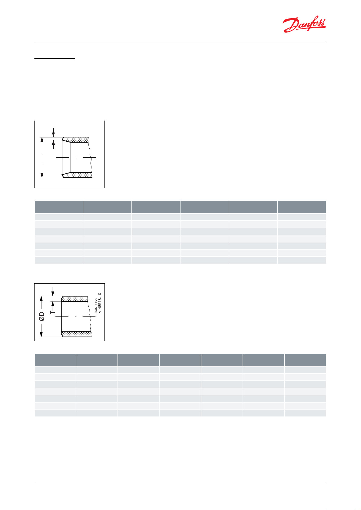
T
ØD
Danfoss
A148B15.10
SizemmSize
in.ØDmmTmmØDin.Tin.
20
(¾)
26.9
2.3
1.059
0.09125(1)
33.7
2.6
1.327
0.10332(1¼)
42.4
2.6
1.669
0.10240(1½)
48.3
2.6
1.902
0.10350(2)
60.3
2.9
2.37
0.1165(2½)
76.1
2.930.1180(3)
88.9
3.2
3.50
0.13
T
ØD
SizemmSize
in.ØDmmTmmØDin.Tin.
Schedule
(20)¾26.9
4.0
1.059
0.15880(25)133.7
4.6
1.327
0.18180(32)1¼42.4
4.9
1.669
0.19380(40)1½48.3
5.1
1.902
0.20180(50)260.3
3.9
2.37
0.1540(65)2½73.0
5.2
2.87
0.2040(80)388.9
5.5
3.50
0.22
40
Pilot operated servo valve, type ICSH 25-80
Connections
There is a wide range of connection types available with ICSH valves:
• D: Butt weld, EN 10220
• A: Butt weld, ANSI (B 36.10)
• SOC: Socket weld, ANSI (B 16.11)
• SD: Solder connection, EN 1254-1
• SA: Solder connection, ANSI (B 16.22)
Figure 7: D: Butt-weld
Table 2: Butt-weld (EN 10220)
Figure 8: A: Butt-weld
ANSI
Table 3: Butt-weld ANSI (B 36.10)
© Danfoss | Climate Solutions | 2021.02 AI260929867804en-000501 | 8
Page 9
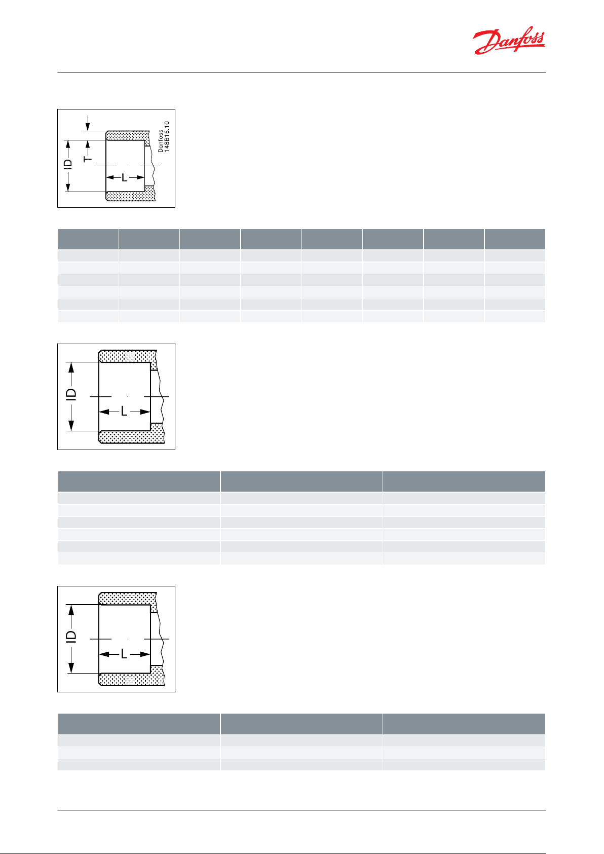
SizemmSize
in.IDmmTmmIDin.Tin.LmmLin.
(20)¾27.2
4.6
1.071
0.181130.51
(25)133.9
7.2
1.335
0.284130.51
(32)1¼42.7
6.1
1.743
0.240130.51
(40)1½48.8
6.6
1.921
0.260130.51
(50)261.2
6.2
2.41
0.24160.63
(65)2½74
8.8
2.91
0.344160.63
L
ID
SizemmIDmmL
mm
22
22.08
16.52828.082635
35.072542
42.072854
54.093376
76.1
33
L
ID
Size
in.IDin.Lin.
⅞
0.875
0.650
1⅛1.125
1.024
1⅜1.375
0.984
Pilot operated servo valve, type ICSH 25-80
Figure 9: SOC: Socket
welding ANSI
Table 4: Socket welding ANSI (B 16.11)
Figure 10: SD: Soldering
Table 5: SD: Soldering (EN 1254-1)
Figure 11: SA: Soldering
Table 6: SA: Soldering (ANSI B 16.22)
© Danfoss | Climate Solutions | 2021.02 AI260929867804en-000501 | 9
Page 10

Size
in.IDin.Lin.
1⅝
1.625
1.1022⅛2.125
1.3002½2.625
1.300
16
2
1
3
4
6
7
5
8
9
10
11
12
13
14
15
17
18
19
20
21
22
23
24
DANFOSS
27H581
No
Part
Material
EN
ASTM
1
Body
Low temperature Steel
G20Mn5QT EN 10213-3
LCC A352
2
Top Cover
Low temperature Steel
P285QH EN-10222-4
LF2 A350
3
Gasket
Fibre non asbestos
4
Gasket
Aluminium
5
Gasket
Aluminium
6
EVM NC
7
Gasket
Nylon8Cap
Steel9Stopper
Nylon10Manual opener
Steel11Needle Housing
Stainless steel
12
Spring Bush
Stainless steel
13
Spring
Steel14Needle
Stainless steel
15
Nozzle
Cast iron
16
Plug
Steel17Piston
Steel
Pilot operated servo valve, type ICSH 25-80
Material specication
Figure 12: ICSH
Table 7: Material and parts list
© Danfoss | Climate Solutions | 2021.02 AI260929867804en-000501 | 10
Page 11

No
Part
Material
EN
ASTM
18
Cylinder
Steel19Spring
Steel20O-ring
Chloroprene (Neoprene)
21
O-ring
Chloroprene (Neoprene)
22
Cone
Steel23Valve Plate
PTFE24Bolt
Stainless steel
A2-70 EN1515-1
A2-70, B1054
L
H4
L3max
L4
H3
L3max
L2
H2
H1
L1
DANFOSS
27H582
ICSH 25-25
L
DINASOCmm135
135
147in5.31
5.31
5.79
ICSH 25-25L1L2
L3max(s1)
L3max(S-2)
L4H1H2H3H4
Weight
mm65146.5
138
123
100.5
39.5
168.561174
3.8 Kgin2.56
5.77
5.43
4.84
3.96
1.56
6.63
2.40
6.85
7.93lb
Pilot operated servo valve, type ICSH 25-80
Valve selection based on capacity calculation
As for extended capacity calculations and valve selection based on capacities and refrigerants, please refer to
Coolselector®2. Rated and extended capacities are calculated with the Coolselector®2 calculation engine to ARI
standards with the ASEREP equations based on laboratory measurements of selected valves.
Download Coolselector®2 for free at coolselector.danfoss.com.
Dimensions
Figure 13: ICSH
Table 8: ICSH 25-25
Table 9: ICSH 25-25
© Danfoss | Climate Solutions | 2021.02 AI260929867804en-000501 | 11
Page 12

ICSH 32
L
DINASOCmm145
145
148in5.71
5.71
5.83
ICSH 32L1L2
L3max(s1)
L3max(S-2)
L4H1H2H3H4
Weight
mm75146.5
138
123
102
42.5
18272187.6
5.1 Kgin2.95
5.77
5.43
4.84
4.02
1.67
7.17
2.83
7.39
11.1 lb
ICSH 40
L
DINASOCmm160
160
180in6.30
6.30
7.09
ICSH 40L1L2
L3max(s1)
L3max(S-2)
L4H1H2H3H4
Weight
mm86146
138
123
102
51.5
186.578193
6.5 Kgin3.39
5.75
5.43
4.84
4.02
2.03
7.34
3.07
7.60
14 lb
ICSH 50
L
DINASOCmm200
200
216in7.87
7.87
8.50
ICSH 50L1L2
L3max(s1)
L3max(S-2)
L4H1H2H3H4
Weight
mm
100
146
138
123
1076120295209
9.4 Kgin3.94
5.75
5.43
4.84
4.21
2.40
7.95
3.74
8.23
20.3lb
ICSH 65
L
DINASOCmm230
230
230in9.06
9.06
9.06
ICSH 65L1L2
L3max(s1)
L3max(S-2)
L4H1H2H3H4
Weight
mm
130
145.6
138
123
106.769222.5
114.5
232
13.7 Kgin5.12
5.73
5.43
4.84
4.20
2.72
8.76
4.51
9.13
29.8lb
ICSH 80
L
DIN
Amm245
245in9.65
9.65
ICSH 80L1L2
L3max(s1)
L3max(S-2)
L4H1H2H3H4
Weight
mm
130
145.6
138
123
106.769222.5
112.5
232
13.7 Kgin5.12
5.73
5.43
4.84
4.20
2.72
8.76
4.43
9.13
29.8lb
Pilot operated servo valve, type ICSH 25-80
Table 10: ICSH 32
Table 11: ICSH 32
Table 12: ICSH 40
Table 13: ICSH 40
Table 14: ICSH 50
Table 15: ICSH 50
Table 16: ICSH 65
Table 17: ICSH 65
Table 18: ICSH 80
Table 19: ICSH 80
NOTE:
Specied weights are approximate values only.
© Danfoss | Climate Solutions | 2021.02 AI260929867804en-000501 | 12
Page 13

+ + =
027H2120
Function module ICS 25-25
027H2200
Top cover ICSH
027H0159
Valve body 25 D (1 in.)
Valve size
Code Number
20 D (¾ in.)
027H2128
35 SD (1⅜ in. SA)
027H2134
22 SD (⅞ in.)
027H2123
20 SOC (¾ in.)
027H2132
25 D (1 in.)
027H2120
28 SA (1⅛ in.)
027H2126
20 A (¾ in.)
027H2131
25 SOC (1 in.)
027H2122
32 D (1¼ in.)
027H2129
22 SA (⅞ in.)
027H2125
25 A (1 in.)
027H2121
20 FPT (½ in.)
027H2133
40 D (1½ in.)
027H2135
28 SD (1⅛ in.)
027H2124
32 A (1¼ in.)
027H2130
25 FPT (1 in.)
027H2127
Pilot operated servo valve, type ICSH 25-80
Ordering
ICSH 25
Ordering from the parts programme
Figure 14: Example (select from below tables ICV 25 valve body w/dierent connections, ICS 25 function module and ICSH 25
top cover)
Figure 15: ICV 25 valve
body
Table 20: ICV 25 valve body w/dierent connections
D = Butt-weld DIN
A = Butt-weld ANSI
J = Butt-weld JIS
SOC = Socket weld ANSI
© Danfoss | Climate Solutions | 2021.02 AI260929867804en-000501 | 13
Page 14

Description
Code Number
ICS 25-5
027H2201
(1)
ICS 25-10
027H2202
(1)
ICS 25-15
027H2203
(1)
ICS 25-20
027H2204
(1)
ICS 25-25
027H2200
(1)
Description
Code Number
Top cover ICSH
027H0159
(2)
Pilot operated servo valve, type ICSH 25-80
SD = Solder DIN
SA = Solder ANSI
FPT = Female Pipe Thread
Figure 16: ICS 25
Table 21: ICS 25 function module
(1)
(1)
Including gasket and O-rings
Including gasket and O-rings
Figure 17: ICSH 25 top
cover
Table 22: ICSH 25 top cover
(2)
(2)
Including bolts, one blanking plug (A+B) and 2 EVM NC
Including bolts, one blanking plug (A+B) and 2 EVM NC
Ordering complete factory assembled valve
(body, function module and top cover)
© Danfoss | Climate Solutions | 2021.02 AI260929867804en-000501 | 14
Page 15

+ + =
027H3120
Function module ICS 32
027H3200
Top cover ICSH
027H0164
Valve body 32 D (1¼ in.)
Available connections
20 D (¾ in.)
25 D (1 in.)
32 D (1¼ in.)
40 D (1½ in.)
35 SD (1⅜ in.
SA)
28 SA (1⅛ in.)
22 SA (⅞ in.)
28 SD (1⅛ in.)
ICSH 25-25
(3)
*
027H2309******
22 SD (⅞ in.)
20 A (¾ in.)
25 A (1 in.)
32 A (1¼ in. )
20 SOC (¾ in.)
25 SOC (1 in.)
20 FPT (½ in. )
25 FPT (1 in. )
ICSH 25-25
(3)
**027H2308**
027H2307**
Pilot operated servo valve, type ICSH 25-80
Figure 18: Vlave assembly
Table 23: ICSH 25-25 connections
(3)
(3)
Including one blanking plug (A+B) and 2 EVM NC
Including one blanking plug (A+B) and 2 EVM NC
ICSH 32
Ordering from the parts programme
Figure 19: Example (select from table ICV 32 valve body w/dierent connections, ICS 32 function module and ICSH 32 top
cover)
© Danfoss | Climate Solutions | 2021.02 AI260929867804en-000501 | 15
Page 16

Connection
Code Number
32 D (11/4 in.)
027H3120
35 SD (13/8 in. SA)
027H3123
40 D (11/2 in.)
027H3125
32 A (11/4 in.)
027H3121
42 SA (15/8 in.)
027H3127
32 SOC (11/4 in.)
027H3122
42 SD (15/8 in.)
027H3128
40 A (11/2 in.)
027H3126
Connection
Code Number
ICS 32
027H3200
(1)
Pilot operated servo valve, type ICSH 25-80
Figure 20: ICV 32 valve body
Table 24: ICV 32 valve body w/dierent connections
D = Butt-weld DIN
A = Butt-weld ANSI
J = Butt-weld JIS
SOC = Socket weld ANSI
SD = Solder DIN
SA = Solder ANSI
FPT = Female Pipe Thread
Figure 21: ICS 32 function module
Table 25: ICS 32 function module
(1)
(1)
Including gasket and O-rings
Including gasket and O-rings
© Danfoss | Climate Solutions | 2021.02 AI260929867804en-000501 | 16
Page 17

Description
Code Number
Top cover ICSH
027H0164
(2)
Available connections
32 D (1¼ in.)
40 D (1½ in.)
42 SA (1⅝ in.)
42 SD (1⅝ in.)
35 SD (1
⅜ in.
SA)
32 A (1¼ in.)
32 SOC (1¼ in.)
40 A (1½ in.)
ICSH 32
(3)
027H3309****
027H3378
027H3377
*
Pilot operated servo valve, type ICSH 25-80
Figure 22: ICSH 32 top
cover
Table 26: ICSH 32 top cover
(2)
(2)
Including bolts, one blanking plug (A+B) and 2 EVM NC
Including bolts, one blanking plug (A+B) and 2 EVM NC
Ordering complete factory assembled valve
(body, function module and top cover)
Figure 23: Assemble valve
Table 27: ICSH 32 connections
(3)
(3)
Including one blanking plug (A+B) and 2 EVM NC
Including one blanking plug (A+B) and 2 EVM NC
* Select from parts programme
© Danfoss | Climate Solutions | 2021.02 AI260929867804en-000501 | 17
Page 18

+ + =
027H4126
Function module ICS 40
027H4200
Top cover ICSH
027H0169
Valve body 50 D (2 in.)
Connections
Code Number
40 D (1½ in.)
027H4120
50 D (2 in.)
027H4126
42 SA (1⅝ in.)
027H4124
42 SD (1⅝ in.)
027H4123
40 A (1½ in.)
027H4121
40 SOC (1½ in.)
027H4122
50 A (2 in.)
027H4127
Pilot operated servo valve, type ICSH 25-80
ICSH 40
Ordering from the parts programme
Figure 24: Example (select from table ICV 40 valve body w/dierent connections, table ICS 40 function module and ICSH 40
top cover)
Figure 25: ICV 40 valve body
Table 28: ICV 40 valve body w/dierent connections
D = Butt-weld DIN
A = Butt-weld ANSI
J = Butt-weld JIS
SOC = Socket weld ANSI
SD = Solder DIN
SA = Solder ANSI
FPT = Female Pipe Thread
Figure 26: ICS 40 function module
© Danfoss | Climate Solutions | 2021.02 AI260929867804en-000501 | 18
Page 19

Description
Code Number
ICS 40
027H4200
(1)
Description
Code Number
Top cover ICSH
027H0169
(2)
Available connections
40 D (1½ in.)
50 D (2 in.)
42 SA (1
⅝ in.)
42 SD (1
⅝ in.)
40 A (1½ in.)
40 SOC (1½ in.)
50 A (2 in.)
ICSH 40
(3)
027H4309***027H4308
027H4307
*
Pilot operated servo valve, type ICSH 25-80
Table 29: ICS 40 function module
(1)
(1)
Including gasket and O-rings
Including gasket and O-rings
Figure 27: ICSH 40 top
cover
Table 30: ICSH 40 top cover
(2)
(2)
Including bolts, one blanking plug (A+B) and 2 EVM NC
Including bolts, one blanking plug (A+B) and 2 EVM NC
Figure 28: Valve assembly
Table 31: Ordering complete factory assembled valve (body, function module and top cover)
(3)
(3)
* Select from parts programme
© Danfoss | Climate Solutions | 2021.02 AI260929867804en-000501 | 19
Including one blanking plug (A+B) and 2 EVM NC
Including one blanking plug (A+B) and 2 EVM NC
Page 20

+ + =
027H5124
Function module ICS 40
027H5200
Top cover ICSH
027H0174
Valve body 65 D (2½ in.)
Connections
Code Number
50 D (2 in.)
027H5120
50 SOC (2 in.)
027H5122
65 D (2½ in.)
027H5124
65 A (2½ in.)
027H5125
54 SD (2⅛ in. SA)
027H5123
50 A (2 in.)
027H5121
Pilot operated servo valve, type ICSH 25-80
ICSH 50
Ordering from the parts programme
Figure 29: Example (select from below table ICV 50 valve body w/dierent connections, ICS 50 function module and ICSH 50
top cover)
Figure 30: ICV 50 valve body
Table 32: ICV 50 valve body w/dierent connections
D = Butt-weld DIN
A = Butt-weld ANSI
J = Butt-weld JIS
SOC = Socket weld ANSI
SD = Solder DIN
SA = Solder ANSI
FPT = Female Pipe Thread
Figure 31: ICS 50 function module
© Danfoss | Climate Solutions | 2021.02 AI260929867804en-000501 | 20
Page 21

Description
Code Number
ICS 50
027H5200
(1)
Description
Code Number
Top cover ICSH
027H0174
(2)
Available connections
50 D (2 in.)
65 D (2½ in.)
54 SD (2
⅛ in. SA)
65 A (2½ in.)
50 A (2 in.)
50 SOC (2 in.)
ICSH 50
(3)
027H5309***027H5308
027H5307
Pilot operated servo valve, type ICSH 25-80
Table 33: ICS 50 function module
(1)
(1)
Including gasket and O-rings
Including gasket and O-rings
Figure 32: ICSH 50 top
cover
Table 34: ICSH 50 top cover
(2)
(2)
Including bolts, one blanking plug (A+B) and 2 EVM NC
Including bolts, one blanking plug (A+B) and 2 EVM NC
Figure 33: Valve assembly
Table 35: Ordering complete factory assembled valve (body, function module and top cover)
(3)
(3)
Including one blanking plug (A+B) and 2 EVM NC
Including one blanking plug (A+B) and 2 EVM NC
* Select from parts programme
© Danfoss | Climate Solutions | 2021.02 AI260929867804en-000501 | 21
Page 22

+ + =
027H6124
Function module Top cover ICSH
027H0179
027H0227
ICS 65 027H6200
ICS 80 027H8200
Valve body 76 SD (2 5/8 in.)
Connections
Code Number
65 D (21/2 in.)
027H6120
65 A (21/2 in.)
027H6121
65 J (21/2 in.)
027H6122
80 D (3 in.)
027H6126
80 A (3 in.)
027H6127
67 SA (2 5/8 in.)
027H6125
76 SD (3 in.)
027H6124
65 SOC (21/2 in.)
027H6123
Pilot operated servo valve, type ICSH 25-80
ICSH 65 and ICSH 80
Ordering from the parts programme
Figure 34: Example (select from table ICV 65 valve body w/dierent connections, table ICS 65-80 function module and table
ICSH 65-80 top cover)
Figure 35: ICV 65 valve body
Table 36: ICV 65 valve body w/dierent connections
D = Butt-weld DIN
A = Butt-weld ANSI
J = Butt-weld JIS
SOC = Socket weld ANSI
SD = Solder DIN
SA = Solder ANSI
FPT = Female Pipe Thread
Figure 36: ICS 65-80 function module
© Danfoss | Climate Solutions | 2021.02 AI260929867804en-000501 | 22
Page 23

Description
Code Number
ICS 65
027H6200
(1)
ICS 80
027H8200
(1)
Description
Code Number
Top cover ICSH (65)
027H0179
(2)
Top cover ICSH (80)
027H0227
(2)
Available connections
65 D (2½ in.)
65 A (2½ in.)
65 SOC (2½ in.)
80 D (3 in.)
80 A (3 in.)
67 SA (2
⅝ in.)
76 SD (3 in.)
65 J (2½ in.)
ICSH 65
(3)
027H6309
027H6311
027H6308****
*
ICSH 80
(3)
***
027H7302
027H7303**
*
Pilot operated servo valve, type ICSH 25-80
Table 37: ICS 65-80 function module
(1)
(1)
Including gasket and O-rings
Including gasket and O-rings
Figure 37: ICSH 65-80 top
cover
Table 38: ICSH 65-80 top cover
(2)
(2)
Including bolts, one blanking plug (A+B) and 2 EVM NC
Including bolts, one blanking plug (A+B) and 2 EVM NC
Figure 38: Valve assembly
Table 39: Ordering complete factory assembled valve (body, function module and top cover)
(3)
(3)
Including one blanking plug (A+B) and 2 EVM NC
Including one blanking plug (A+B) and 2 EVM NC
* Select from parts programme
© Danfoss | Climate Solutions | 2021.02 AI260929867804en-000501 | 23
Page 24

Description
Code no.
ICV 25 PM Valve housing
027H2119
(1)
ICV 32 PM Valve housing
027H3129
(1)
ICV 40 PM Valve housing
027H4128
(1)
ICV 50 PM Valve housing
027H5127
(2)
ICV 65 PM Valve housing
027H6128
(2)
PM
REMOVE
ICV PM
ICV PM
DROP IN
ICM
ICS/H
ICLX
CUSTOMIZE
Description
Code no.
ICV 25 (H)A4A Valve housing
027H2304
(3)
ICV 32 A4A Valve housing
027H3130
(3)
ICV 32 HA4A Valve housing
027H3131
(3)
Pilot operated servo valve, type ICSH 25-80
Accessories
ICV PM anged valve housings
ICV PM anged valve housings can replace the PM valves on already installed refrigeration systems.
Pressure range
The ICV PM valve housing is designed for a max. working pressure of 28 bar / 406 psig and therefore a suitable
replacement for PM valves in the service market. They also oer the same drop-in dimensions as the PM valves.
Table 40: ICV PM valve housing
(1)
(1)
Includes ICV PM valve housing, ange gaskets and ange bolts.
Includes ICV PM valve housing, ange gaskets and ange bolts.
(2)
(2)
Includes ICV PM valve housing, ange gaskets, ange bolts and ange nuts.
Includes ICV PM valve housing, ange gaskets, ange bolts and ange nuts.
Function modules and top covers must be ordered separately (see the section “Ordering”).
Figure 39: ICV PM anged valve housing
Figure 40: Function modules and top covers
ICV (H)A4A anged valve housings
ICV (H)A4A anged valve housings can replace the (H)A4A valves on already installed refrigeration systems.
Pressure range
The ICV (H)A4A valve housing is designed for a max. working pressure of 28 bar g / 406 psig and therefore a suitable
replacement for (H)A4A valves in the service market. They also oer the same drop-in dimensions as the (H)A4A
valves.
Table 41: ICV (H)A4A anged valve housings
© Danfoss | Climate Solutions | 2021.02 AI260929867804en-000501 | 24
Page 25

Description
Code no.
ICV 40 (H)A4A Valve housing
027H4129
(3)
ICV 50 (H)A4A Valve housing
027H5128
(3)
ICV 65 (H)A4A Valve housing
027H6129
(3)
(H)A4A
REMOVE
ICV (H)A4A
ICV (H)A4A
DROP IN
ICM
ICS/H
ICLX
CUSTOMIZE
Description
Code number
Blanking plug incl.
at gasket
027F1046
Pilot operated servo valve, type ICSH 25-80
(3)
(3)
Includes ICV (H)A4A valve housing, ange gaskets, ange bolts and ange nuts.
Includes ICV (H)A4A valve housing, ange gaskets, ange bolts and ange nuts.
Figure 41: ICV (H)A4A anged valve housing
Function modules and top covers must be ordered separately (see the section “Ordering”).
Figure 42: Function modules and top covers
Figure 43: Plug
Table 42: Blanking plug A + B for pilot valves
© Danfoss | Climate Solutions | 2021.02 AI260929867804en-000501 | 25
Page 26

The ICV valve concept has been designed to fulll global refrigeration requirements.
ICSH valves
Nominal bore
DN≤ 25 (1 in.)
DN 32 - 80 (1¼ - 3 in.)
Classied for
Fluid group I
Category
Article 4, paragraph 3
II
File name
Document type
Document topic
Approval authority
033F0685.AK
EU Declaration
EMCD/PED
Danfoss
033F0691.AE
Manufacturers Declaration
RoHS
Danfoss
Д-DK.РА01.B.71727_20
EAC Declaration
PED
EAC
0045 202 1204 Z 00354 19 D 001(00)
Pressure - Safety Certicate
-
TÜV
19.10325.266
Marine - Safety Certicate
-
RMRS
Pilot operated servo valve, type ICSH 25-80
Certicates, declarations, and approvals
The list contains all certicates, declarations, and approvals for this product type. Individual code number may have
some or all of these approvals, and certain local approvals may not appear on the list.
Some approvals may change over time. You can check the most current status at danfoss.com or contact your local
Danfoss representative if you have any questions.
Table 43: Approvals
Table 44: ICSH valves
Table 45: Certicates and declarations
© Danfoss | Climate Solutions | 2021.02 AI260929867804en-000501 | 26
Page 27

Online support
Danfoss oers a wide range of support along with our products, including digital product information, software,
mobile apps, and expert guidance. See the possibilities below.
The Danfoss Product Store
The Danfoss Product Store is your one-stop shop for everything product related—no matter where
you are in the world or what area of the cooling industry you work in. Get quick access to essential
information like product specs, code numbers, technical documentation, certications, accessories,
and more.
Start browsing at store.danfoss.com.
Find technical documentation
Find the technical documentation you need to get your project up and running. Get direct access to
our ocial collection of data sheets, certicates and declarations, manuals and guides, 3D models
and drawings, case stories, brochures, and much more.
Start searching now at www.danfoss.com/en/service-and-support/documentation.
Danfoss Learning
Danfoss Learning is a free online learning platform. It features courses and materials specically
designed to help engineers, installers, service technicians, and wholesalers better understand the
products, applications, industry topics, and trends that will help you do your job better.
Create your Danfoss Learning account for free at www.danfoss.com/en/service-and-support/learning.
Get local information and support
Local Danfoss websites are the main sources for help and information about our company and
products. Find product availability, get the latest regional news, or connect with a nearby expert—all
in your own language.
Find your local Danfoss website here: www.danfoss.com/en/choose-region.
Spare Parts
Get access to the Danfoss spare parts and service kit catalog right from your smartphone. The app
contains a wide range of components for air conditioning and refrigeration applications, such as
valves, strainers, pressure switches, and sensors.
Download the Spare Parts app for free at www.danfoss.com/en/service-and-support/downloads.
Coolselector®2 - nd the best components for you HVAC/R system
Coolselector®2 makes it easy for engineers, consultants, and designers to nd and order the best
components for refrigeration and air conditioning systems. Run calculations based on your operating
conditions and then choose the best setup for your system design.
Download Coolselector®2 for free at coolselector.danfoss.com.
Danfoss can accept no responsibility for possible errors in catalogues, brochures and other printed material. Danfoss reserves the right to alter its
products without notice. This also applies to products already on order provided that such alterations can be made without subsequential
changes being necessary in specications already agreed. All trademarks in this material are property of the respective companies. Danfoss and
the Danfoss logotype are trademarks of Danfoss A/S. All rights reserved.
© Danfoss | Climate Solutions | 2021.02 AI260929867804en-000501 | 27
 Loading...