

Page 1
Installation and Advanced Programming Instructions
HP8211-1RJ and HP8321-1RJ Heat Pump Thermostats
These instructions are intended for installation and first time set up of the thermostat.
For day to day use please refer to the User Instruction Sheet.
Contents
- Ordering Details for Series 8000 Product Range _________________________ 1
- Unpacking and installing the thermostat ________________________________ 1
- Setting the DIP switches (optional) ____________________________________ 2
- Attaching the thermostat to the wallplate ________________________________ 2
- Wiring Instructions _________________________________________________ 3
- Using remote sensors (optional) _____________________________________ 3
- Programming the event times (setbacks) and temperatures ________________ 4
- Summary table of Advanced Programing Mode (APM) options ______________ 5
- Detailed description of Advanced Programming Mode (APM) options ________ 6
- Trouble shooting guide _____________________________________________ 8
- Thermostat specification table _______________________________________ 8
- Contact information ________________________________________________ 8
Ordering Details for Series 8000 Product Range
Number of Stages & Application Model Code Numb er
1 Heat 1 Cool for heat/cool systems (no occupancy relay) HC8111-1 087N6807NA
1 Heat 1 Cool for heat/cool or heat pump systems HC8111-1RJ 087N7224NA
2 Heat 2 Cool for heat/cool systems HC8221-1J 087N6939NA
2 Heat 2 Cool for heat/cool systems (battery operated) HC8220-1J 087N6940NA
2 Heat 1 Cool for heat pump systems HP82 11-1RJ 087N 6959 NA
3 Heat 2 Cool for heat pump systems HP8321-1RJ 087N6963NA
Accessories
Remote room sensor TS2/2 087N728500
Duct mounting sensor TS5 087N681200
Outdoor sensor TS6 087N681300
Optional wall plate for 8000 Series thermostats 181 0 087N8000WP
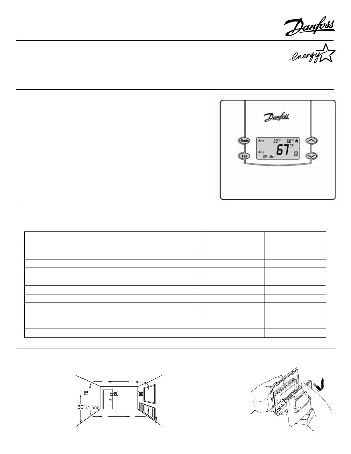
Unpacking and installing the thermostat
1. Thermostat location 2. Unpacking the thermostat
Note: a wall plate (code no:
087N8000WP) is available to
cover a wider area when
retrofitting.
1
Page 2
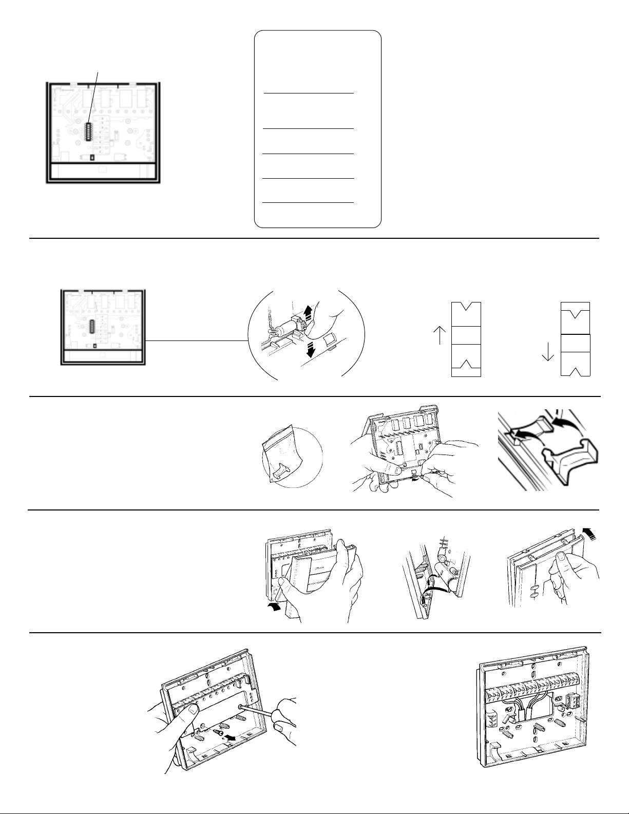
Setting the DIP Switches
Switch Location
Switch
Non-prog = 1 Off & 2 On
2 Events = 1 Off & 2 Off
4 Events = 1 On & 2 Off
6 Events = 1 On & 2 On
7 Day = 3 On & 4 Off
5/2 Day = 3 Off & 4 Off
24hr = 3 On & 4 On
Keyboard
Changeover
Aux Heat
Occ Relay
➔➔
➔ = On
➔➔
➔
= Off
Disable = 5 On
Enable = 5 Off
Aut o = 6 Off
Man = 6 On
Electric = 7 Off
Fossil = 7 On
N/O = 8 Of f
N/C = 8 On
*
*
*
*
A) It is advisable to make DIP switch settings prior
to installing the thermostat on the wallplate.
B) If Keyboard Disable function is required (DIP
switch 5), do not set until any advanced
programming options are completed, and user
programs have been set.
C) To return the thermostat DIP switches to the
factory setting set switches as indicated by
*
*
How to disable the reset button
To prevent unauthorised resetting of programs and advanced programing options the reset button can be disabled.
Enabled On
*
How to Lock the Front Cover
If locking is required fit locking piece before fitting the
thermostat to wallplate. Do not close the front cover
until the thermostat has been fitted to the wallplate.
To open a locked cover, slide a flat-blade screwdriver
in from the side between the bottom of the thermostat and center locking tab. Gently twist the blade to
pry open the cover.
Attaching the Thermostat onto the
Wallplate (see illustrations to right)
To remove the thermostat from the wallplate, open
the front cover, place a flat blade screw driver into
the slots on top of the thermostat and gently twist.
Once both slots are done, gently pull top of thermostat towards you. Note: do not press down on the
white tabs as this could damage the thermostat.
Disabled Off
= reset enabled
▲
ON
= reset disabled
▲
ON
Wiring Access
1. Removing the thermostat
terminal cover
2
2. Correct wiring access
a) Feed the wires
through the access in
the rear of the
wallplate.
b) Wires must enter
from below the
terminal block
screws
Page 3
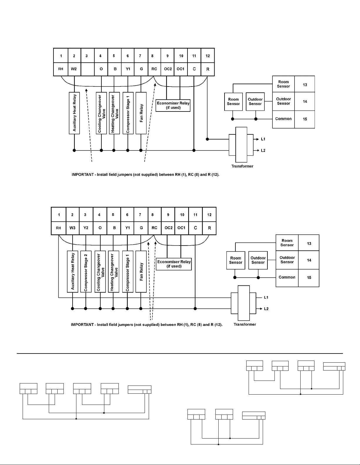
Wiring Instructions for the thermostat
HP8211-1RJ Model
HP8321-1RJ Model
Wiring Instructions for the Remote Sensors (if averaging is required)
1
TS2/2 Sensor
A
2
TS2/2 Sensor
C
B
A
3
TS2/2 Sensor
A
C
B
B
THERMOSTATS
C
ALL 8000
15
13
1
TS2/2 Sensor
A
2
TS2/2 Sensor
C
B
A
3
TS2/2 Sensor
C
B
A
4
TS2/2 Sensor
A
C
B
B
THERMOSTATS
C
ALL 8000
15
13
1
TS2/2 Sensor
A
2
TS2/2 Sensor
A
C
B
B
THERMOSTATS
C
ALL 8000
15
13
3
Page 4
PROGRAMMING THE EVENT TIMES (SETBACKS) AND TEMPERATURES
Note : This thermostat is delivered with DIP switches and advanced programming options factory preset to cover most common applications. Should you require to change from any of the factory presets it is advisable to do so prior to setting the event times and
temperatures as they may affect the following sequence.
Keyboard lockout (DIP switch 5) should not be in the enable position (Off) until after programming is complete.
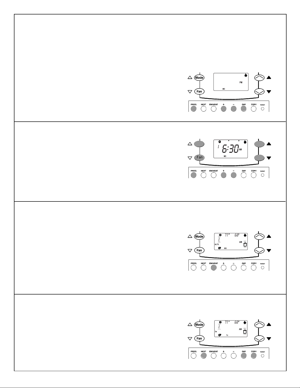
Step 1: - Setting the current time and day
PM
68
AM
1.1 Press the PROG button to enter programming mode. If necessary, adjust
the day using the DAY button and the time using the + or – buttons.
Note : It is advisable to fill out the appropriate THERMOSTAT SETTING
TEMPLATE in the users instructions before proceding to the next step.
Step 2: - Programming the first event
2.1 Press the PROG button a second time to enter the event-programming
mode.
2.2 Adjust the start time for the first event of the day using the +
or – buttons.
2.3 Adjust the temperatures for the first event of the day using the buttons to
the left of the display for cooling and the buttons to the right for heating.
Mode
Fan
12:00
MO
77
6:30
MO
Note : If Option 4 of the advanced programming section has been
enabled (factory default is disabled) the fan operation and occupancy
relay can also be set at this time, following Step 3 below.
Step 3: - Selecting fan operation (skip to Step 4 if Option 4 of the APM
is in the DISable setting)
3.1 Using the EM HEAT button simply cycle through the following combinations to find the right selection.
3.2 Fan AUTO and building symbol flashing = Fan AUTO, Unoccupied
Event Occupation relay open *.
3.3 Fan ON and building symbol flashing = Fan ON, Occupancy Relay
open.
3.4 Fan AUTO and building symbol steady = Fan AUTO, Unoccupied Event
Occupation relay closed *.
3.5 Fan ON and building symbol steady = Fan ON, Unoccupied Event
Occupation relay closed *.
* With DIL switch 8 set to ON (Occ N/C). If set to Occ N/O the reverse state
will apply to the Occupation relay.
Step 4: - Programing other events
4.1 Press NEXT to move to next event, repeat steps 2-3 until all events for
current day are programmed. Number of Events will be defined by DIP
switches 1 & 2 (factory default is 2 per day).
4.2 Press the DAY button to advance to the next day, or next group of days,
and repeat steps 1-5 until all programs are set.
AUTO
O
N
77
68
6:30
MO
77
68
6:30
TU
AM
AM
Note : To copy a program from one day to the next press DAY then
COPY.
4
Page 5

)
g cy
g cy
e
p
y
A
y
g
pag
y
ADV ANCED PROGRAMMING MODE (APM) OPTIONS SUMMAR Y
For further details of the APM options refer to pages 6, 7 & 8.
NOTE: If centigrade display has been selected then all temperatures will be the °C equivalent of the °F temperatures shown below.
Option Description Default Setting Optional Setting Comments
NE (next timed
1 Temperature override timer
2 Fan run-on timer after each cooling cycle OFF
3 Fan run-on timer after each heating cycle OFF
Enable or Disable occupancy relay and Smart
4
Fan programming
5 Fan Lock ALL LOC
6 Use of keyboard disable (DIP switch 5) NOR FUL
7 Minimum deadband 5˚F 2˚F, 7˚F or 10˚F
8 Max Heating Temp 86˚F 85˚F to 43˚F Used in conjunction with Option A
9 Min Cooling Temp 61˚F 62˚F to 104˚F Used in conjunction with Option b
A Min Heating Temp 43˚F 44˚F to 86˚F Used in conjunction with Option 8
b Max Cooling Temp 104˚F 103˚F to 61˚F Used in conjunction with Option 9
c Optimum start control for heating 0 (off) 1-8
d Optimum start control for cooling 0 (off) 1-8 See Option c above
E Calibration 0˚F + 3˚F to -3˚F Raises or lowers display temp in 1˚F steps
F Compressor minimum off time 4 mins 3 mins or 2 mins Sets the compressor min Off time for each cycle
H Compressor minimum on time 2 mins 0-4 mins Sets the compressor min On time for each cycle
L Low balance point (low temp cut off) 16˚F
N High balance point 50˚F 32˚F to 70˚F or Off
r Remote room sensor disable En (able) DIS (able)
event will reset
the override
DIS (able) En (able)
1, 2, 3, 4Hr, or
DIS
30, 60 or 90
seconds
30, 60 or 90
seconds
-22˚F to +60˚F or
Off
1, 2, 3 or 4 hours override, or override disabled
Fan runs on for additional 30, 60 or 90 seconds after
each coolin
Fan runs on for additional 30, 60 or 90 seconds after
each heatin
When enabled this feature sets 3 functions:
1. Occupancy relay can be set to open or close at
each event tim
2. The fan can be set for AUTO or ON at each event
time.
3. Optimum Start Control will be effective at each
ied Event time.
Occu
When this feature is disabled the Occupancy Relay
and smart fan energizes at first programed event
time and de-energizes at the last programed event
time, and OSC will only operate at the first event time
of the da
LL allows AUTO, ON or SMART fan to be selected.
LOC disables the fan button and locks the
thermostat in SMART fan mode.
NOR = PROG key disabled and temperature override
limited to 3˚F up or down from setpoint. This feature
may be used in conjunction with options 1 & 5. FUL
= full ke
Minimum temperature difference between heating
and coolin
Sets the maximum amount of start up time for
heating. 1 = 15 mins, 2 = 30 mins up to 8 =
120mins. Refer to table on
Below this temp the thermostat switches off the heat
pump and runs with auxiliary heat alone. Only
available when outdoor sensor is installed
Above this temp the thermostat switches off the
auxiliary heat and runs with the heat pump alone.
available when outdoor sensor is installed
Onl
Disables or enables the remote room sensor. Only
available when remote sensor is installed
cle
cle
.
board lockout.
setpoints
e 7
5
Page 6

DETAILED DESCRIPTION OF ADVANCED PROGRAMMING MODE (APM) OPTIONS
To enter Advanced Programming Mode (APM) press and hold FAN and COPY buttons for 3 seconds. Note: the thermostat must be in
nomal running mode (not programming mode).
When in APM mode use the ▲ and ▼ buttons to scroll through the options available. Use the Next button to move onto the subsequent
option.
Option 1 Setting temperature override duration timer
(not available if “Non-Prog” is selected on DIP switches 1 & 2)
This feature allows the building owner to determine the duration of any temporary temperature override selected by the
user.
Option 2 Setting fan run-on after cooling demand
This feature allows the installer to select a timed fan run-on following each cooling demand.
Option 3 Setting fan run-on after heating demand
This feature allows the installer to select a timed fan overrun following each heating demand.
Option 4 Enabling or disabling programmable occupancy programming
(not available if “Non-Prog” is selected on DIP switches 1 & 2)
This feature allows the operation of the fan to be programmed to Auto or On, and the occupancy relay contacts to be
opened or closed, during each event. Setting these options is affected during the event programming process. See step
3 para 3.1 through to 3.5 on page 4.
Option 5 Setting fan operation mode
(not available if “Non-Prog” is selected on DIP switches 1 & 2)
This feature allows the building owner to determine what mode the fan will operate in and what overrides will be available
to the user.
Option 6 Selecting extent of keyboard disable function. active only when dip switch 5 is set to “keyboard disable”
This feature allows installer to determine the extent of the disablement of keyboard functions if DIP switch 5 is set to
“Keyboard disable”. See table below:
Feature Part (nor) Full
Access to programming mode ✘✘
Access to advanced programming mode ✘✘
Access to service mode ✘✘
Access to Hold & Vacation mode ✘✘
Access to Daylight Savings Time Change ✓✓
Selection of AM/PM or 24 hour clock ✓✘
Selection of Fahrenheit or Centrigrade scaling ✓✘
Mode select (auto/heat/cool/off) ✓✘
Mode select (EM heat, Heat-pump models) ✓✘
Fan Mode (Auto/On/Smart-fan) ✓✘
Temperature override (including duration) ✓✘
View temperature information ✓✓
Change display time to temperature ✓✓
Note : Settings of options 7 through b are dependent on each other. Not all settings will be accepted and an ERR message
may be experienced. If this occurs press (▲) or (▼) to make the setting valid. Alternatively press NEXT button to return to
option 7 and review the settings.
Option 7 Setting heating / cooling dead-band adjustment (not available if “Changeover Manual” is selected on DIP switch 6)
This feature allows the installer or the building owner to determine minimum dead-band between heating and cooling.
Option 8 Setting maximum heating temperature set point
This feature allows the building owner to determine the maximum heating temperature available to the user.
Option 9 Setting minimum cooling temperature set point
This feature allows the building owner to determine the minimum cooling temperature available to the user.
6
Page 7
Option A Setting minimum heating temperature set point
This feature allows the building owner to determine the minimum heating temperature available to the user.
Option b Setting maximum cooling temperature set point
This feature allows the building owner to determine the maximum cooling temperature available to the user.
Option C Optimum start control, heating (OSC)
(not available if “Non-Prog” is selected on DIP switches 1 & 2)
This feature allows the installer to enable the optimum start control for the heating event. If enabled it allows the heating
to be turned on earlier than the programmed time in order to ensure that recovery of room temperature is achieved by the
programmed time. The setting is dependent upon the capacity of the system and the building heat gain/loss characteristics and can be determined from the following table. If Option 4 (occupancy and smart-fan programming) has been
enabled, the optimum start control will operate at each occupied event change that requires an increase in temperature.
If Option 4 has been left in the disabled mode the optimum start controller will only function prior to the first event (Event
1) of the day
Estimate of system
temperature rise capability Optimum start Maximum duration
in 30 minutes control settings of early on period
N/A 0 Optimizer disabled
16°F 1 15 mins
8°F 2 30 mins
5-6°F 3 45 mins
4-5°F 4 60 mins
3-4°F 5 75 mins
2-3°F 6 90 mins
2°F 7 105 mins
1-2°F 8 120 mins
Option d Opti m u m start c o n t r ol, cooling (OSC) (not available if “Non-Prog” is selected on DIP switches 1 & 2)
This feature allows the installer to enable the optimum start control for the cooling event. If enabled it allows the cooling
to be turned on earlier than the programmed time in order to ensure that recovery of room temperature is achieved by the
programmed time. The setting is dependent upon the capacity of the system and the building heat gain/loss characteristics and can be determined from the following table. If Option 4 (occupancy and smart-fan programming) has been
enabled, the optimum start control will operate at each occupied event change that requires a decrease in temperature. If
Option 4 has been left in the disabled mode the optimum start controller will only function prior to the first event (Event 1)
of the day .
Estimate of system
temperature reduction Optimum start Maximum duration
capability in 30 minutes control settings of early on period
N/A 0 Optimizer disabled
16°F 1 15 mins
8°F 2 30 mins
5-6°F 3 45 mins
4-5°F 4 60 mins
3-4°F 5 75 mins
2-3°F 6 90 mins
2°F 7 105 mins
1-2°F 8 120 mins
Option E Setting thermostat calibaration
This feature allows the installer to calibrate the temperature shown in the LCD display by ± 3°F.
7
Page 8

 Loading...