

Page 1
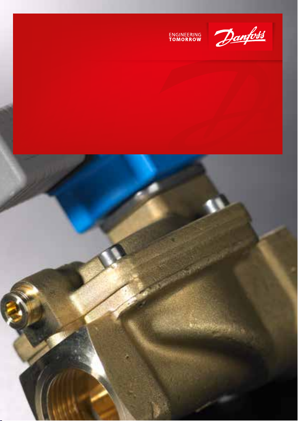
Installation guide
How to use solenoid valves
Making it easy to be efficient
ia.danfoss.com
Page 2
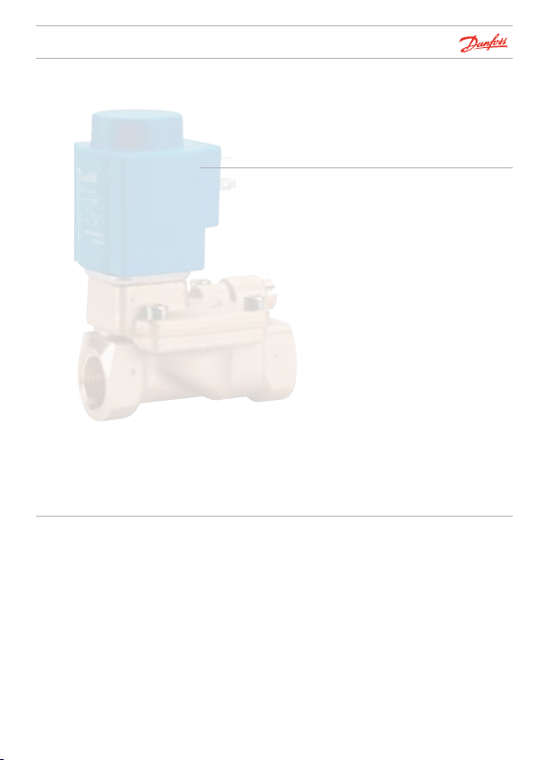
How to use
solenoid valves
This booklet has been compiled to help in the installation of
compact and high performance solenoid valves and in
locating faults in systems with solenoid valves.
The compact range has small physical dimensions for control
of flow where space is limited.
The high performance range is a sturdy and universal valve
program for control of flow in industrial plants and within
heating and sanitary systems.
Note that this booklet describes only brass solenoid valves.
For other types, please contact Danfoss.
If you need help choosing a solenoid valve, visit the online
valve selector at valveselector.danfoss.com
Flexible and
user-friendly
© Danfoss | DCS (RJA) | 2015.11
Danfoss solenoid valve bodies and electrical coils are normally
supplied separately and then combined together. They are
assembled quickly and simply without any tools.
This provides optimum product flexibility and availability. If a
coil needs replacement it can be done without stopping or
draining any system.
The solenoid valves are also available as assembled units if
required.
IC.PS.600.A8.02
Page 3

Contents
Identification .........................................................................................................3
Installation...............................................................................................................6
How to choose ..................................................................................................13
Valve overview ..................................................................................................18
Seal material .......................................................................................................22
Coils ..........................................................................................................................23
Opening and closing times .......................................................................25
Fault location ......................................................................................................27
Spare parts high performance range
......................................................
Spare parts compact range.......................................................................41
Tools .........................................................................................................................42
32
© Danfoss | DCS (RJA) | 2015.11
IC.PS.600.A8.02 | 1
Page 4
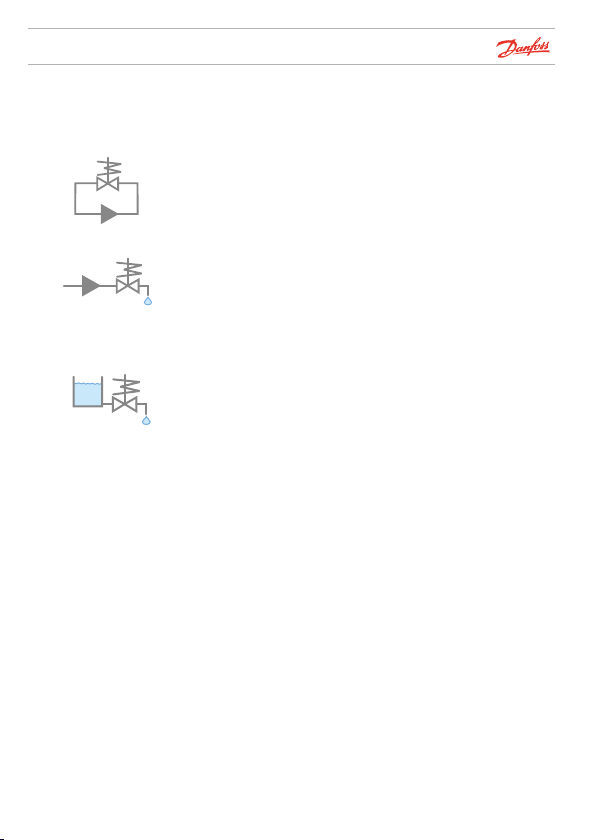
Solenoid valves
Choosing the correct
solenoid valve
Symbolise valves used in a closed circuit system, typically
with low differential pressures.
Symbolise valves used in an open system.
Used typically for drinking water.
Differential pressure higher than 0.5 bar.
Symbolise valves used in a drain system.
Note ! For more details see How to choose on page 13
© Danfoss | DCS (RJA) | 2015.11
IC.PS.600.A8.02 | 2
Page 5
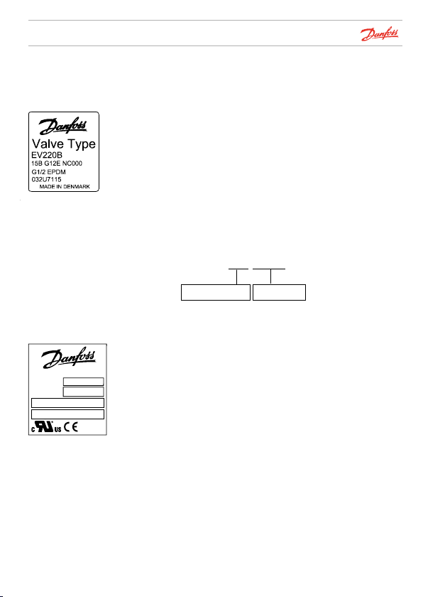
Identification
Choosing the correct
solenoid valve
Illustration 1
MADE IN DENMARK
018F4517
Spare part no.
-40T40 °C
Tambient
24V 60Hz 8.5W 14VA
24V 50Hz 10.5W 16VA
Illustration 2
F4507
BQ024CS
Option 1: Identification using silver label (← 2011)
Illustration 1 shows the label with relevant information that is
attached to the coil.
The example here is from an EV220B solenoid valve:
15: 15 mm orifice
B: Brass body material
G 12: ISO 228/1, 1/2 inch connection
E: EPDM seal material
NC: Normally closed
If the the coil label cannot be read, the valve can be identified
from the letter/number combination stamped in the valve body.
Example:
506U4042
Week 50 2006 042U4042
The coil type (BQ024CS) is printed on the front of the coil as
well as voltage (V) and frequency (Hz) - see illustration 2.
© Danfoss | DCS (RJA) | 2015.11
IC.PS.600.A8.02 | 3
Page 6
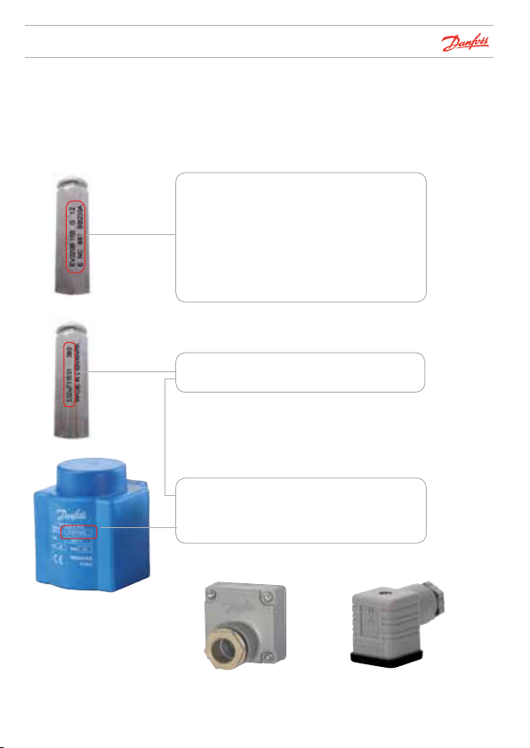
Identification
Option 2 (2011 →)
Printing on armature tube replaces silver labels and date /
code no. stamping for identification of the valve.
Type Designation
EV220B = Valve type
15 = 15 mm orifice
B = Brass body material
G 12 = ISO 228/1, ½ inch connection
E = EPDM seal material
NC = Normally closed
667 = Options
BB230A = Coil
Production Time
380 = Week 38 2010
032U711531 = Code Number
Note down following information
Valve code no: ______________
Sparepart no.: ______________
Plug
© Danfoss | DCS (RJA) | 2015.11
042N0156018Z0081
IC.PS.600.A8.02 | 4
Page 7

Identification
Valve identification
problem
If above mentioned method is not possible, state the
following when ordering Danfoss solenoid valves as
replacements:
• Application (closed circuit, open
system or drain application)?
• Function (Normally open or normally closed)?
• End connection?
• Medium (water, oil, air, etc.)?
• Kv value?
• Coil voltage?
• Alternating (AC) or direct current (DC)?
© Danfoss | DCS (RJA) | 2015.11
IC.PS.600.A8.02 | 5
Page 8
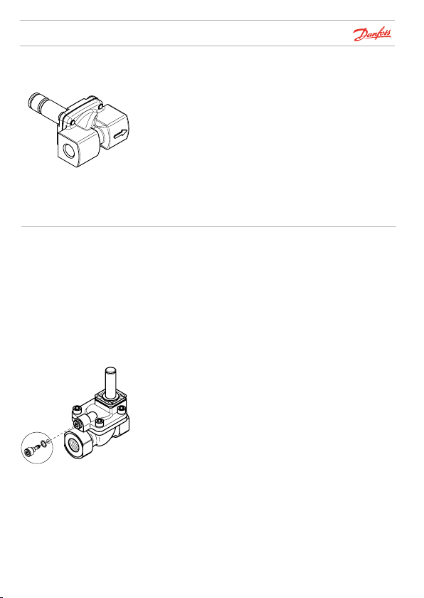
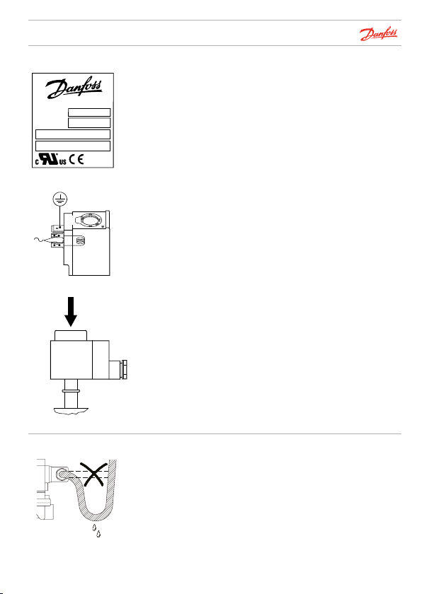
32U1171.11
Installation
Flow direction
Water hammer
To be able to operate correctly, all solenoid valves must be
installed with the arrow cast on the body pointing in the
direction of flow.
Water hammer is a typical result of high liquid velocity
(high pressure and high flow velocity through small pipe
diameters).
There are several reasonable solutions to the problem:
1. Reduce the pressure by installing a pressure reduction
valve ahead of the solenoid valve. If possible, increase the
pipe diameter.
2. Damp the water hammer by installing a flexible hose or
flexible buffer ahead of the solenoid valve.
3. Use a solenoid valve of the type EV220B 15 – EV220B 50.
The equalizing orifice can be replaced by a version with
smaller diameter. This gives a longer closing time (see
Danfoss
“Spare parts” and “Opening and closing times”).
Equalizing orifice
© Danfoss | DCS (RJA) | 2015.11
IC.PS.600.A8.02 | 6
Page 9
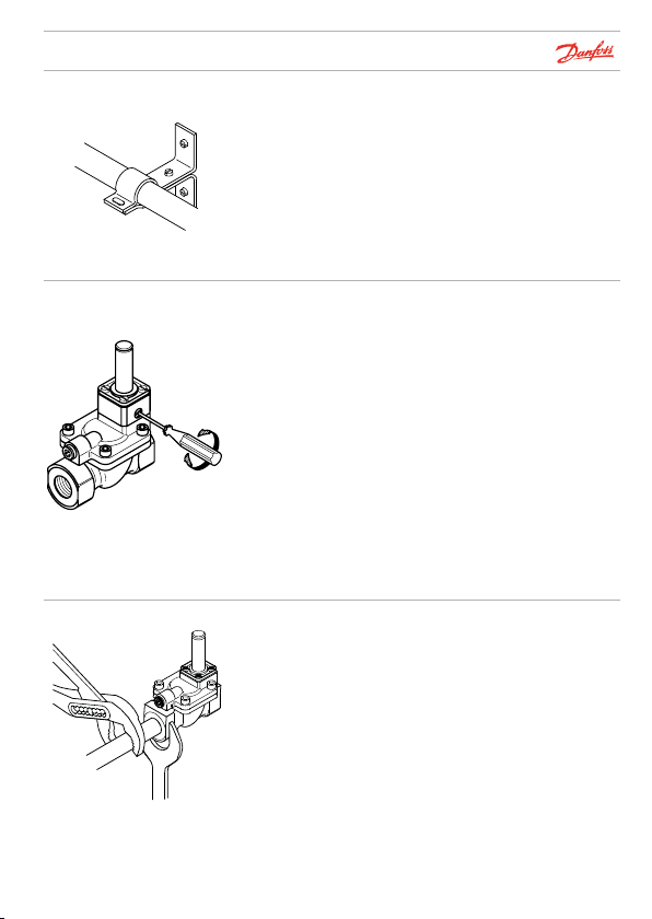
Danf
32U1521.11
Installation
Pipe
Test pressure
Tightening up
Danfoss
A32U1175.11
The pipes on both sides of the valve must be securely
fastened.
When applying test pressure: All valves in the system must
be open. There are three ways of doing this:
1. By applying voltage to the coil
2. By opening the valves manually(when the manual
override accessory is fitted)
3. By connecting the Danfoss permanent magnet
(see "Tools", page 42)
Note that the manual opening unit is not supplied as
standard, but as an accessory for EV220B 15 – EV220B 50
valves (see page 33).
Remember to screw the opening unit back (CLOCKWISE)
before starting up the system, otherwise the valve cannot
close.
Always use counter-force when tightening up pipe connections, i.e. use a spanner on both the valve body as well as on
the pipe connector (as shown).
oss
© Danfoss | DCS (RJA) | 2015.11
IC.PS.600.A8.02 | 7
Page 10
Danfoss
Installation
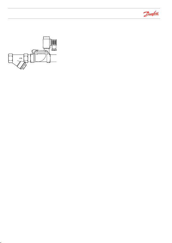
Dirt in the system
32U1715.11
Always flush out piping before installing a solenoid valve. If
there is dirt in the medium, a filter should be installed ahead
of the valve.
© Danfoss | DCS (RJA) | 2015.11
IC.PS.600.A8.02 | 8
Page 11
Danf
32U1744.11
32U1743.11
Installation
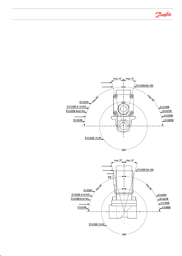
Installing the coil
Servo-operated and
assisted lift
servo-operated valves
Danfoss recommends that the solenoid valve be installed
with coil upwards. This minimises the risk of dirt collecting in
the armature tube.
If “clean” media is used, i.e. media containing no dirt particles,
the solenoid valve will operate when installed in the
orientation as shown below.
EV245B
EV251B
EV222B
Danfoss
EV245B
EV251B
EV222B
© Danfoss | DCS (RJA) | 2015.11
oss
IC.PS.600.A8.02 | 9
Page 12
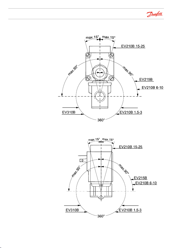
Installation
Direct-operated valves
Danfoss
32U1745.11
© Danfoss | DCS (RJA) | 2015.11
EV310A
EV310A
EV210A
EV210A
IC.PS.600.A8.02 | 10
Danfoss
32U1746.11
Page 13
Installation
Coil
MADE IN DENMARK
018F4517
Spare part no.
-40T40 °C
Tambient
24V 60Hz 8.5W 14VA
24V 50Hz 10.5W 16VA
F4507
BQ024CS
Cable connection
Check to ensure that the coil operating voltage is correct
(see text on coil, in “Volt”). Also ensure that the data is correct
(voltage and frequency) and matches the supply. If the two
sets of data do not correspond, the coil might burn out.
As far as possible, always choose single-frequency coils; they
give off less heat than double-frequency versions.
The coil has three pins. The middle pin is marked according to
the illustration (left) and must be used for earthing.
The two other pins are coil terminals and either can be used
for the phase or neutral supply. The terminals can be used
respectively for phase and neutral as required.
Please note for high performance range!
When mounting the clip-on coil, simply press it gently onto
the armature, until it clicks into place. An O-ring should be
fitted over the armature tube before fitting the coil.
Cable entries must always be screwed in correctly.
The cable must be installed as shown in the illustration to
avoid water running into the terminal box.
© Danfoss | DCS (RJA) | 2015.11
IC.PS.600.A8.02 | 11
Page 14
Installation
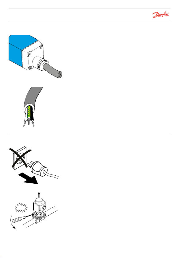
Cable
Coil replacement
To avoid moisture penetrating in the terminal box, the whole
cable diameter must be secured in the entry. For this reason,
always use round cables as they are the only type that can be
effectively sealed.
Note the colours on the cable leads. Yellow/green is always
earth. The other leads should be for the phase and neutral
supply.
Please note for clip-on coils:
When replacing a coil, use a screwdriver to lever it from the
armature.
Caution: Before removing a coil, voltage must be
disconnec ted, otherwise the coil will burn out.
OFF
© Danfoss | DCS (RJA) | 2015.11
IC.PS.600.A8.02 | 12
Page 15

How to choose
Product selection made easy for installers
With only a few clicks Danfoss Product Selector can help you find the right product for
stan dard applications.
The tool is developed to help wholesalers, retailers, installers and the end user to clarify
their needs within solenoid valves.
With Danfoss’ web based tool, you can access anywhere; from your laptop or smartphone,
as long as you have internet acces.
In the solenoid valve selector you only need to know 5 things:
1 Medium
2 System
3 Function
4 Connection size
5 Coil voltage
The Danfoss selector then presents a result for you which can be sent to your email, SMS or be
printed out.
Danfoss though recommends OEM-customers, which typically get customized products for
their applications, to contact their Danfoss distributor.
See how easy it is:
http://valveselector.danfoss.com/
"Scan me with your
smartphone"
© Danfoss | DCS (RJA) | 2015.11
IC.PS.600.A8.02 | 13
Page 16

How to choose
If you do not have internet access try indentify all relevant parameters.
This includes:
1 Capacity / Kv - value
2 Pressure conditions
3 Media conditions
4 Other conditions
Capacity / Kv - value:
1 Specifies how many m3/ hour (capacity) water is passing through the valve at a
differential pressure at 1 bar.
2 Is a result of all the different constants coming from shape of orifices, units etc.
which are reduced to one new constant, the k
3 Is used to calculate capacity:
4 ρ = density (kg / m
5 ΔP = P
- P
1
3
)
2
Q = Kv
Pressure conditions
Open system (system with drain)
In an open system the pressure conditions are well-defined.
This enables clarification as to whether there is sufficient pressure differential to be able to
open a servo-operated valve. The following types of valves are well-suited for use in open
systems:
EV210B and EV310B direct-operated solenoid valves
EV220B, EV220A and EV225B servo-operated solenoid valves
Closed circuit (circulating system)
In a closed circuit system the pressure conditions are undefined. Therefore a solenoid valve
capable of opening without pressure differential is required.
EV250B assisted lift servo-operated valve
EV210B and EV310B direct-operated solenoid valves
- value.
v
3
∆P
[m
/ h]
√
ρ
© Danfoss | DCS (RJA) | 2015.11
IC.PS.600.A8.02 | 14
Page 17

How to choose
Operating pressure
Valves in the standard range are designed for pressure of max 6–30 bar – the actual figure
depends on the type of valve.
The product range includes valves for special application, designed for pressures of up to 80 bar.
The large standard range combined with these valves enable the use of Danfoss solenoid valves
for all types of systems, wether with normal or more extreme inlet pressures.
Differential pressure/ MOPD
1 Difference between inlet pressure and outlet pressure (∆P = P1 - P2).
2 Max. permissible differential pressure against which the valve can open
3 Also specified as MOPD: Maximum Opening Pressure Differential
4 MOPD specifies the differential pressure value in worst case:
• 100 % duty rate
• Maximum medium and ambient temperature
• Nominel voltage, typically -10%
5 Specified pressure is often limited by endurance demands more than MOPD
Media conditions
The valves are designed to resist the temperatures normally found in industrial applications.
If the temperature is outside these limits, there is a risk of the valve not functioning correctly
because of, for example, rubber materials becoming hard. Exceeding the temperature rating
can also result in the shortening of valve life. If the valve is to be used in a special application,
with a temperature in excess of the rated limits, there are valves available in the product range
which have been designed for use in higher temperature systems.
© Danfoss | DCS (RJA) | 2015.11
IC.PS.600.A8.02 | 15
Page 18

How to choose
The characteristics of the medium
The valves have been designed for use with different media.
In general the following is valid:
Valves containing EPDM-rubber are suitable for water and steam*.
Valves containing FKM-/NBR-rubber are suitable for oil and air.
Incorrect use of valve types:
1 If a valve containing EPDM-rubber is used for a medium containing oil (compressed air
normally contains particles of oil from the compressor) the rubber will expand and the
valve will not be able to function optimally.
2 A valve containing FKM-/NBR-rubber can be used for water. However for servo-operated
valves, the water temperature must be kept below 60 °C for FKM, 90 °C for NBR. If this
temperature is exceeded it will have a negative effect on the life of the valve.
Other media
For slightly aggressive media (e.g. demineralised water) dezincificationresistant brass valves
must be used. Stainless steel valves are used for more aggressive media.
*For steam temperatures above 120 °C there is a type of valve especially designed for steam
Ambient temperature
The ambient temperature must be within certain limits for the coil to function optimally.
See data sheet for coils.
© Danfoss | DCS (RJA) | 2015.11
IC.PS.600.A8.02 | 16
Page 19

How to choose
Water hammer
All piping systems with relatively high flow rates are susceptible to water hammer when a
valve is opened or closed. A damped solenoid valve ( eg. EV220B 15–50) should be used if
there is a risk of water hammer. After installation the valve can be adjusted for water hammer
by changing a replaceable equalizing orifice. See "Spareparts" page 32.
Filter
In systems with contaminated media there is a risk of moving parts in a valve not working as
intended. Dirt is the most common cause of function failure in solenoid valves. To help avoid
this problem we suggest the fitting of a filter on the upstream side of the valve.
Coil voltage and power
It is necessary to know which voltage (Volt AC/DC nominel ± 10%) is available within an
application to select the correct coil. The maximum permissible differential pressure can also
be increased by fitting a more powerful coil. The coil power depends on the type of coil (BA,
BB, AM etc.).
Other environmental factors
In wet or very humid environments, coils with IP67 enclosure classification must be used.
Valve function
Most industrial systems operate with a de-energised closed valve (NC = normally closed).
Our valve range also offers de-energised open valves (NO = normally open) for applications
requiring this feature.
© Danfoss | DCS (RJA) | 2015.11
IC.PS.600.A8.02 | 17
Page 20

Valve overview - High performance (blue) range
Air and
neutral
gasses Water Oil Steam
EV210B
ü ü ü
EV310B
ü ü ü
EV220B
ü ü ü
EV250B
ü ü ü ü
EV225B BQ coil
Medium
© Danfoss | DCS (RJA) | 2015.11
ü
IC.PS.600.A8.02 | 18
Page 21

Valve overview - High performance (blue) range
Characteristics
Connection
[ISO 228/1] Function
G 3/8" - G 1" NC/NO
EV210B covers a wide range of direct-operated 2/2-way solenoid
valves for universal use. EV210B is a real robust valve program
with high performance and can be used in all kind of tough
working conditions.
Description
G 1/8" - G 3/8" NC/NO
G 1/4" - G 1" NC/NO
G 1/2" - G 2" NC/NO
G 3/8" - G 1" NC
G 1/4" - G 1" NC
© Danfoss | DCS (RJA) | 2015.11
EV310B is a direct-operated 3/2- way solenoid valve. The valve is
especially used in connection with air-operated valves to allow air
supply and air relief for the air actuator.
EV220B 6–22 is a direct servo-operated 2/2-way solenoid valve
program. This program is especially for OEM applications demanding a robust solution and moderate flow rates.
EV220B 15–50 is a universal indirect servo-operated 2/2-way
solenoid valve program. Valve body in brass, dezincification
resistant brass and stainless steel ensures that a broad variety of
applications can be covered.
EV250B with assisted lift is especially to use in closed circuits with
low differential pressure, but demanding moderate flow rates.
Valve body in DZR brass ensures a long life, even in connection
with aggressive steam media.
The EV225B design is based on a PTFE diaphragm and valve body
in dezincification resistant brass, ensuring high reliable function
and long life even in connection with contaminated steam.
IC.PS.600.A8.02 | 19
Page 22

Valve overview - Compact (black) range
EV220A
Medium Characteristics
Air and
neutral
gasses Water Oil Steam
ü ü ü ü
© Danfoss | DCS (RJA) | 2015.11
IC.PS.600.A8.02 | 20
Page 23

Valve overview - Compact (black) range
Connection
[ISO 228/1] Function
G 1/4" - G 2" NC
G 1/4" - G 1" NO
Description
EV220A is a compact indirect servo-operated 2/2 way solenoid
valve program with brass valve body for robust industrial
application.
© Danfoss | DCS (RJA) | 2015.11
IC.PS.600.A8.02 | 21
Page 24

[bar]
Seal material
Media table
Seal material
[°C]
Medium EPDM
1)
Water / glycols - 30 – 140
Oil - 0 – 100 -10 – 90 -
Air - 0 – 100 -10 – 90 -
Steam up to 140 - up to 185
* Direct-operated valves
1)
FKM NBR PTFE
0 – 60
0 – 100*
-10 – 90 -
EPDM is suitable for water and steam within the
© Danfoss | DCS (RJA) | 2015.11
illustrated ranges
IC.PS.600.A8.02 | 22
Page 25

Coils
Coil consumption Supply voltage / frequency1)Code number
BB coils (IP65)
10 W without cable plug 220 – 230 V AC / 50 Hz 018F7351
10 W without cable plug 110 V AC / 50-60 Hz 018F7360
10 W without cable plug 24 V AC / 50 Hz 018F7358
18 W without cable plug 24 V AC 018F7397
Cable plug for BB coils 042N0156
BE coil (IP67)
10W with terminal box 220 – 230 V AC / 50 Hz 018F6701
10W with terminal box 115 V AC / 50 Hz 018F6711
10W with terminal box 48 V AC / 50 Hz 018F6709
10W with terminal box 24 V AC / 50 Hz 018F6707
18W with terminal box 24 V AC 018F6757
BG coils (IP67)
20 W with terminal box 24 V AC 018F6857
BQ coil
10W without cable plug 230 V AC / 50 Hz 018F4511
10W without cable plug 110 V AC / 50 Hz 018F4519
10W without cable plug 24 V AC / 50 Hz 018F4517
Cable plug for BQ coils 042N0156
For installations sensitive to noise
BN coil (hum-free, IP65)
20 W with 1 m cable 220 – 230 V AC / 50-60 Hz 018F7301
1)
For other voltages or coil types, see coil data sheet.
© Danfoss | DCS (RJA) | 2015.11
IC.PS.600.A8.02 | 23
Page 26

Coils
Coil consumption Supply voltage / frequency
1)
Code number
AM coils (IP00-IP65)
7.5 W without cabel plug 110 V AC / 50/60 Hz 042N0845
7.5 W without cabel plug 220–230 V AC / 50/60 Hz 042N0840
9.5 W without cabel plug 24 V DC 042N0843
Cable plug for AM coils 042N0156
1)
For other voltages or coil types, see coil data sheet.
© Danfoss | DCS (RJA) | 2015.11
IC.PS.600.A8.02 | 24
Page 27

Opening and closing times
Closing times and water
hammer
High performance (blue)
range
Compact (black) range
With the larger valves, very short closing times can cause
water hammer.
The EV220B servo-operated valves have damped closing and
fulfil EN60730-2-8 specifications.
The table gives the opening/closing times of the various
types, but it must be emphasised that tube dimensions /
lengths and differences in operating conditions - especially
pressure - can cause deviations from the values given.
Type Opening [ms] Closing [ms]
EV210B 1.5 10 20
EV210B 3 20 20
EV210B 6 20 20
EV250B 12 100 100
EV250B 18 150 100
EV250B 22 150 100
EV220B 10 50 300
EV220B 12 60 300
EV220B 15 40 350
EV220B 20 40 1000
EV220B 25 300 1000
EV220B 32 1000 2500
EV220B 40 1500 4000
EV220B 50 5000 10000
EV310B 2 10 – 20 10 – 20
Type Opening [ms] Closing [ms]
EV220A 6 40 250
EV220A 10 50 300
EV220A 12 60 300
EV220A 14 100 400
EV220A 18 200 500
EV220A 22 200 500
EV220A 32 2500 4000
EV220A 40 4000 6000
EV220A 50 5000 10000
© Danfoss | DCS (RJA) | 2015.11
IC.PS.600.A8.02 | 25
Page 28

Opening and closing times
Changing opening and
closing times
Please note for high performance type.
EV220B 15 – EV220B 50 closing times can be changed by
replacing the equalizing orifice at the inlet side of the valve
(see "Water hammer" page 17, and "Spare parts" page 32). To
decrease water hammer, choose a smaller equalizing orifice.
The table shows the opening and closing times depending
on the equalizing orifice chosen (standard times marked in
bold). The times stated cover water as a medium, and are
for guidance only. Tube dimensions / lengths and operating
conditions, for example differential pressure, may influence
the values.
Orifice EV220B 15 EV220B 20 EV220B 25 EV220B 32 EV220B 40 EV220B 50
mm
Grooves
Open
Close
Open
Close
Open
Close
Open
Close
Open
Close
Open
0.5 1 0.04 0.35 0.04 1.0 0.11 3.0 1.6 6.0 1.3 8.0 3.4 40.0
0.8 2 0.04 0.3 0.04 0.5 0.3 1.0 1.0 2.5 1.5 4.0 3.6 11.0
1.2 3 0.04 0.12 0.04 0.25 0.30 0.5 1.2 1.0 1.5 2.0 5.0 10.0
1.4 4 0.04 0.1 0.06 0.18 0.30 0.4 1.0 0.8 2.0 1.5 5.2 6.5
Close
© Danfoss | DCS (RJA) | 2015.11
IC.PS.600.A8.02 | 26
Page 29

Fault location
Symptom: Solenoid valve does not open
Probable cause Remedy
No voltage on coil Check whether valve is de-energised open or closed (NO
Incorrect voltage / frequency Check to make sure the coil's electrical require ments are
Coil burnt out See page 31.
Diff. pressure too high Check coil data. If necessary, replace coil with correct version.
Diff. pressure too low Check coil data and differential pressure. If necessary,
Damaged / bent armature tube Replace valve.
Dirt at diaphragm
Dirt in valve seat / dirt in armature /
armature tube
2)
2)
Corrosion Replace defective component(s)
Components missing after valve
dismantling
1)
See "Spare parts" page 32
2)
If there is repeated build up of dirt in the armature / armature tube, consider the installation af an isolating
diaphragm kit, if applicable (see "Spare parts" page 32)
or NC):
1. Use a magnetic detector
2. Lift coil slightly and note whether it offers resistance
against lifting
Note: Never remove a coil with voltage applied - it may
burn out.
Check relay contacts. Check lead connections. Check fuses.
the same as the installation supply. Measure the operating
voltage at the coil. Permissible voltage variation:
±10% for dual frequency; DC and NO applications
+10% / -15% for AC on single frequency voltages
If necessary, replace coil with correct version.
Reduce differential pressure, e.g. by limiting inlet pressure.
replace coil with correct version.
Clean diaphragm. If necessary, replace defective
component(s)1).
Clean valve; if necessary, replace defective component(s).
1)
.
1)
Fit missing component(s)
.
© Danfoss | DCS (RJA) | 2015.11
IC.PS.600.A8.02 | 27
Page 30

Fault location
Symptom: Solenoid valve partly opens
Probable cause Remedy
Differential pressure too low Check valve data, incl. differential pressure. Replace valve
Damaged or bent armature tube Replace valve.
Dirt at diaphragm Clean diaphragm.
Dirt in valve seat / dirt in armature /
armature tube
2)
Corrosion Replace defective component(s)
Components missing after valve
dismantling
1)
See "Spare parts" page 32
2)
If there is repeated build up of dirt in the armature / armature tube, consider the installation af an isolating
diaphragm kit, if applicable (see "Spare parts" page 32)
with correct version.
1)
If necessary, replace defective component(s)
.
Clean valve, if necessary, replace defective component(s).
1)
.
1)
Fit missing component(s)
.
© Danfoss | DCS (RJA) | 2015.11
IC.PS.600.A8.02 | 28
Page 31

Fault location
Symptom: Solenoid valve does not close/partly closes
Probable cause Remedy
Voltage remains on coil First lift coil slightly and note whether it offers
Dirt in or closed pilot orifice /
equalizing piece
Manual opening unit cannot be
screwed back after use.
Pulsation in pressure line.
Differential pressure too high in
open position.
Pressure on outlet side periodically
higher than pressure on inlet side.
Damaged / bent armature tube Replace valve.
Defective valve plate, diaphragm
or valve seat
Diaphragm upside down Check correct installation of valve
Dirt in valve seat/dirt in armature
tube
Corrosion, pilot / main orifice Replace defective components.
Valve installed wrong way round Check liquid flow direction and make sure the arrow is
Components missing after valve
dismantling
1)
See "Spare parts" page 32
resistance.
Note: Never remove a coil with voltage applied - it might
burn out.
Check wiring diagram and wiring.
Check relay contacts.
Check lead connections.
Clean orifice with needle or similar (max. dia. 0.5 mm).
Blow clean with compressed air.
If necessary, replace defective component(s).
Check position of opening unit and adjust as necessary.
Check valve data.
Check pressure and liquid flow.
Replace valve with one more suitable.
Check rest of installation.
Check pressure and liquid flow.
Replace defective component(s)
1)
.
1)
.
Clean valve; if necessary, replace defective components.
pointing in the same direction.
1)
Fit missing component(s)
.
© Danfoss | DCS (RJA) | 2015.11
IC.PS.600.A8.02 | 29
Page 32

Fault location
Symptom: Solenoid valve making noise
Probable cause Remedy
Hum Hum caused by AC frequency can be removed by changing
Water hammer when valve opens
Water hammer when valve closes
Differential pressure too high and /
or pulsation in pressure line
to coil with rectifier (see page 23).
See "Installation".
Check valve data and differential pressure.
Check pressure and liquid flow.
Replace with more suitable valve.
Check rest of installation.
© Danfoss | DCS (RJA) | 2015.11
IC.PS.600.A8.02 | 30
Page 33

Fault location
Symptom: Coil burnt - cold with voltage on
Probable cause Remedy
Incorrect voltage / frequency Check coil data.
Coil short-circuit
(could be moisture in coil)
Armature sluggish
1) Damaged / bent armature tube
2) Damaged armature
3) Dirt in armature tube
Temperature of medium too high Check valve and coil data in relation to installation
Ambient temperature too high If possible, move valve to colder surroundings.
If necessary, change to correct coil type.
Check wiring diagram and wiring.
Check maximum voltage variation:
Permissible voltage variation:
±10% for dual frequency; DC and NO applications
+10% / -15% for AC on single frequency voltages
Check rest of installation for possible short-circuiting.
Check lead connections at coil.
When fault has been found, replace coil. (See also "Coil" in
section "Installation"). Consider fitting a 'clip-on' style coil
with addional sealing O-ring (for high performance range only)
Replace defective component(s).
Remove dirt.
specification.
Change to suitable coil or valve.
Check valve and coil data in relation to installation
specification.
Increase ventilation around valve and coil.
.
© Danfoss | DCS (RJA) | 2015.11
IC.PS.600.A8.02 | 31
Page 34

Spare parts high performance range
Normally open
components (NO)
The set contains locking button and nut for coil, normally open
assembly kit (armature and armature tube) and an O-ring.
Code number
Type
FKM seal
material
1)
EPDM seal
material
EV210B 1.5 – EV210B 4.5 NO 032U2004 032U2005
EV220B 6 NO 032U0166 032U0165
EV220B 10 NO 032U0167 -
EV220B 15 – EV220B 50 NO 032U0295 032U0296
NO components are also available for Danfoss valves with other seal
materials.
1)
See page 22 for description of seal materials
1)
© Danfoss | DCS (RJA) | 2015.11
IC.PS.600.A8.02 | 32
Page 35

32U1785.11
Spare parts high performance range
Manual override unit
tool operated
Danfoss
32U947.11
Manual override unit
hand operated
The manual opening unit for EV220B 15 – EV220B 50 can be
used to open and close the valve in the event of power failure
or when applying test pressure.
Material
Brass, size
DN 15–32, seal NBR
Brass, size
DN 40–50, seal NBR
Stainless steel, seal
NBR
Media
temperature [°C] Code number
-10 – 90 032U0150
-10 – 90 032U0260
-10 – 90 032U0149
Used for manual override in event of power failure.
Material
Stainless steel,
seal EPDM
Media
temperature [°C] Code number
-30 – 120 032U7390
Danfoss
© Danfoss | DCS (RJA) | 2015.11
IC.PS.600.A8.02 | 33
Page 36

Spare parts high performance range
Spare parts set for
EV210B NC
Isolating diaphragm kit
for EV210B 1.5 –
EV210B 4.5 NC
and EV220B 15 –
EV220B 50 NC
The spare parts set contains:
Locking button
Nut for coil
Armature with valve plate and spring
O-rings
EPDM versions
Type Code number
EV210B 6, EV210B 8, EV210B 10 032U2006
FKM versions
Type Code number
EV210B 1.5 – EV210B 4.5 032U2003
EV210B 6, EV210B 8, EV210B 10 032U2011
1)
See page 22 for description of seal materials
Avoids build up of contaminates that can block movement of
the armature. Permits use of more agressive media that would
normally attack the armature. Gel filled; guarentees operation
after long periods on inactivity.
Seal material
1)
EPDM
1)
FKM
1)
See page 22 for description of seal materials
Media
temperature [°C]
-20 – 50
0 – 50
Code number
042U1009
042U1010
© Danfoss | DCS (RJA) | 2015.11
IC.PS.600.A8.02 | 34
Page 37

Spare parts high performance range
Spare parts set for
EV220B 6 – EV220B 12
NC
The spare parts set contains:
Locking button
Nut for coil
Armature with valve plate and spring
Diaphragm
2 O-rings
EPDM versions
Valve type Code number
EV220B 6 NC 032U1062
EV220B 10 NC 032U1065
EV220B 12 NC 032U1068
Spare parts sets are also available for Danfoss EV220B valves with
other seal materials (see page 22 for description of seal materials)
© Danfoss | DCS (RJA) | 2015.11
IC.PS.600.A8.02 | 35
Page 38

Spare parts high performance range
Spare parts set for
EV220B 15 – EV220B 50
Danfoss
32U11786.10
The spare parts set contains:
Locking button and nut for the coil
Armature with valve plate and spring
O-ring for the armature tube
Spring and diaphragm
2 O-rings for the pilot system
O-ring and gasket for the equalizing orifice
Equalizing orifice
Type Seal material Code number
EV220B 15 EPDM
EV220B 20 EPDM
EV220B 25 EPDM
EV220B 32 EPDM
EV220B 40 EPDM
EV220B 50 EPDM
Spare parts sets are also available for Danfoss EV220B valves with other
seal materials.
1)
See page 22 for description of seal materials
1)
032U1071
1)
1)
1)
1)
1)
032U1073
032U1075
032U1077
032U1079
032U1081
© Danfoss | DCS (RJA) | 2015.11
IC.PS.600.A8.02 | 36
Page 39

Spare parts high performance range
Equalizing orifice
The kit comprises:
An equalizing orifice includes 2 O-rings. The valves closing
time can be changed by installing an equalizing orifice of a
size which deviates from the standard valve:
• A shorter closing time is obtained with a larger orifice
(the shorter closing time, the greater risk of water
hammering)
• A longer closing time is obtained with a smaller orifice.
See also “Opening and closing times”, page 25.
Equalizing
orifice size
[mm] Seal material Applicable in Code number
EV220B 15
0.5 EPDM
0.8 EPDM
1.2 FKM
1.2 EPDM
1.4 FKM
Equalizing orifice sets are also available for Danfoss EV220B valves
with other seal materials.
1)
See page 22 for description of seal materials
1)
EV220B 20
EV220B 25
1)
EV220B 32
EV220B 40
EV220B 25
1)
EV220B 32
1)
EV220B 50 032U0086
EV220B 40
1)
EV220B 50
032U0082
032U0084
032U0085
032U0087
© Danfoss | DCS (RJA) | 2015.11
IC.PS.600.A8.02 | 37
Page 40

Spare parts high performance range
Spare parts set for
EV250B 12 –
EV250B 22 NC
EPDM seal material
Spare parts set for
EV250B 12 –
EV250B 22 NC
FKM seal material
The spare parts kit comprises:
1. O-ring for coil
2. 4 screws
3. Complete NC actuator unit with diaphragm, assist spring,
armature, closing spring, cover and armature tube
Valve type Code number
EV250B 10 – EV250B 12 BD 032U5315
EV250B 18 – EV250B 22 BD 032U5317
The spare parts kit comprises:
1. O-ring between armature tube and cover
2. Service element consisting of an armature with valve
plate and spring fitted on the diaphragm
Valve type Code number
EV250B 10 – EV250B 12 BD 032U5271
EV250B 18 – EV250B 22 BD 032U5273
© Danfoss | DCS (RJA) | 2015.11
IC.PS.600.A8.02 | 38
Page 41

Spare parts high performance range
Spare parts set for
EV250B 12 –
EV250B 22 NO
Spare parts kit
for EV310B
The spare parts kit comprises:
1. O-ring for coil
2. 4 screws
3. Complete NO actuator unit with diaphragm, assist spring,
NO armature unit and cover
Valve type Seal material Code number
EV250B 10 – EV250B 12 BD
EV250B 18 – EV250B 12 BD
EV250B 10 – EV250B 22 BD
EV250B 10 – EV250B 22 BD
EPDM 032U5319
FKM 032U5320
EPDM 032U5321
FKM 032U5322
The spare parts kit comprises:
Armature with mounted spring
Type Seal material Code number
NC FKM 032U2033
NO FKM 032U2035
© Danfoss | DCS (RJA) | 2015.11
IC.PS.600.A8.02 | 39
Page 42

Spare parts high performance range
Spare parts kit for
EV225B 6 – EV225B 25
Coil for BQ high
performance steam valve
Spare parts kit for EV225B comprises:
Armature with valve plate and spring
Closing spring
Diaphragm
O-ring
Type Code number
EV225B 6 – EV225B 10 032U3171
EV225B 15 032U3172
EV225B 20 – EV225B 25 032U3173
Coil consumption [W]ACSupply voltage [V]/
10 230 / 50 018F4511
10 24 / 50 018F4517
10 110 / 60 018F4519
frequency [Hz] Code number
© Danfoss | DCS (RJA) | 2015.11
IC.PS.600.A8.02 | 40
Page 43

Spare parts high performance range
Spare parts kit for
EV220A 6 – EV220A 50
NC
Spare parts kit comprising:
Armature assembly
Diaphragm assembly
Armature spring
Diaphragm spring
2 O-rings
Type Seal material Code number
EV220A 6 – EV220A 10 B EPDM 042U1000
EV220A 6 – EV220A 10 B NBR 042U1001
EV220A 6 – EV220A 10 B FKM 042U1002
EV220A 12 – EV220A 14 B EPDM 042U1003
EV220A 12 – EV220A 14 B NBR 042U1004
EV220A 12 – EV220A 14 B FKM 042U1005
EV220A 18 – EV220A 22 B EPDM 042U1006
EV220A 18 – EV220A 22 B NBR 042U1007
EV220A 18 – EV220A 22 B FKM 042U1008
EV220A 32 B EPDM 042U1037
EV220A 32 B NBR 042U1038
EV220A 32 B FKM 042U1046
EV220A 40 B EPDM 042U1039
EV220A 40 B NBR 042U1040
EV220A 40 B FKM 042U1047
EV220A 50 B EPDM 042U1041
EV220A 50 B NBR 042U1042
EV220A 50 B FKM 042U1048
© Danfoss | DCS (RJA) | 2015.11
IC.PS.600.A8.02 | 41
Page 44

Tools
Magnetic field indicator
Permanent magnet
This handy key ring tool reacts to magnetic fields from
solenoid valves. Place the indicator close to the coil, and the
red-white disc will prove the coil to be active by rotating.
With this tool it is possible to operate solenoid valves without
wiring up the electrical coil.
Please contact your local Danfoss office to obtain these popular tools.
© Danfoss | DCS (RJA) | 2015.11
IC.PS.600.A8.02 | 42
Page 45

© Danfoss | DCS (RJA) | 2015.11
IC.PS.600.A8.02 | 43
Page 46

Subheading Myriad Pro Semibold 7 pt.
How to use solenoid valves
Making it easy to be efficient
© Danfoss | DCS (RJA) | 2015.11
IC.PS.600.A8.02 | 44
 Loading...