

How to design balancing and control solutions for energy efficient hydronic applications in residential and commercial buildings
Danfoss How to design balancing and control solutions for energy efficient hydronic applications in residential and commercial buildings Application guide
Page 1

Application guide
Hydronic applications
Commercial
Hydronic applications
How to design
balancing and control solutions for
energy ecient hydronic applications
in residential and commercial buildings
44
applications with
detailed descriptions
about the investment,
design, construction
and control
Residential
Mixing loop
AHU application
AHU heating
AHU application
AHU cooling
hbc.danfoss.com
1
Chillers applications Boilers applications Hot water
Page 2
Content structure in this guide
1. Hydronic applications
1.1 Commercial
1.1.1 Variable ow
1.1.2 Constant ow
1.2 Residential
1.2.1 Two-pipe system
1.2.2 One-pipe system
1.2.3 Heating – special application
Typical page shows you:
Chapter
Schematic drawing
2. Mixing loop
3. AHU applications
3.1 AHU applications heating
3.2 AHU applications cooling
4. Chillers applications
5. Boiler applications
6. Hot water applications
Recommendation Type of solution
7. Glossary and abbreviations
8. Control and valve theory
9. Energy eciency analyses
10. Product overview
Application
General system description
Danfoss products
Performance indicators
Application details
2
Page 3
Introduction Notes
Return of investment
poor exellent
poor exellent
Design
acceptable
acceptable
Designing HVAC systems is not that simple. Many factors need to be considered
before making the nal decision about the heat- and/or cooling load, which terminal units
to use, how to generate heating or cooling and a hundred other things.
This application guide is developed to help you make some of these decisions by showing
the consequences of certain choices. For example, it could be tempting to go for
the lowest initial cost (CAPEX) but often there would be compromises on other factors, like
the energy consumption or the Indoor Air Quality (IAQ). In some projects the CAPEX might
be the deciding factor but in another ones it is more about energy eciency or control
precision, therefore it diers from project to project. We collected the most important
information concerning a particular solution on a single page with clear indications what
consequences can be expected when certain choices are made.
The aim of this guide was not to cover each and every application because that would
be impossible. Every day, smart designers come up with new solutions that might be
relevant only to one specic problem or that is solving new problems. That is what engineers
do. The drive for greener, more energy-friendly solutions is creating new challenges every
day, so there are always some new applications. In this particular guide we will nd to cover
the applications that are the most common.
Danfoss also has many competent people available that can support you with specic
challenges or that can support you with calculations. Please contact your local Danfoss
oce for support in your native language.
We hope this guide will help you in your daily work.
Each application shown here is analyzed for four aspects:
Return on Investment, Design, Operation/Maintenance, Control
Return of investment
poor exellent
Design
poor exellent
acceptable
acceptable
All of them are marked as:
Technically and economically optimized solutions as recommended by Danfoss.
This solution will result in eciently operating systems.
Depending on the situation and the particularities of the system this will result in a good
installation. However, some trade-os are made.
Operation/Maintenance
poor exellent
Control
poor exellent
Recommended
Acceptable
acceptable
acceptable
This system is not recommended since it will result in expensive and inecient systems or
the Indoor Air Quality is not ensured.
Not Recommended
3
Page 4

Table of Contents
Content structure in this guide 2
Typical page shows you: 2
Introduction 3
1. Hydronic applications
1.1Hydronic applications – commercial buildings 6
1.1.1 Commercial - Variable ow
1.1.1.1 Variable ow: Pressure Independent Control (PICV) with ON/OFF actuator 8
1.1.1.2 Variable ow: Pressure Independent Control (PICV) with proportional control 9
1.1.1.3 Variable ow: Pressure Independent Control (PICV) with digital actuator 10
1.1.1.4 Variable ow: Flow limitation (with ow limiter) on terminal unit with ON/OFF or modular actuator 11
1.1.1.5 Variable ow: Dierential pressure control with ON/OFF or modulation 12
1.1.1.6 Variable ow: Shell and Core installation for Oces and Shopping malls* 13
1.1.1.7 Variable ow: Manual balancing 14
1.1.1.8 Variable ow: Manual balancing with reverse return 15
1.1.1.9 Variable ow: Four-pipe Changeover (CO6) for radiant heating/cooling panels,
chilled beams, etc. with PICV control valve 16
1.1.1.10 Variable ow: Two-pipe heating/cooling system with central changeover* 17
1.1.2 Commercial - Constant ow
1.1.2.1 Constant ow: 3-way valve with manual balancing (in fan-coil, chilled beam etc. application) 18
1.1.2.2 Constant ow: 3-way valve with ow limiter on terminal units (fan-coil, chilled beam etc. application) 19
1.2 Hydronic applications - residential buildings
1.2.1 Residential - Two pipes system
1.2.1.1 Two-pipe radiator heating system – risers with, thermostatic radiator valves (with presetting) 20
1.2.1.2 Two pipe radiator heating system – risers with, thermostatic radiator valves (without presetting) 21
1.2.1.3 Pressure Independent Control for radiator heating system 22
1.2.1.4 Subordinated risers (staircase, bathroom, etc.) in two- or one-pipe radiator heating system without thermostatic valve 23
1.2.1.5 Δp control for manifold with individual zone/loop control 24
1.2.1.6 Δp control and ow limitation for manifold with central zone control 25
1.2.2 Residential - One pipe system
1.2.2.1 One-pipe radiator heating system renovation with automatic ow limitation
and possible self-acting return temperature limitation 26
1.2.2.2 One-pipe radiator heating system renovation with electronic ow limitation and return temperature control 27
1.2.2.3 One-pipe radiator heating system renovation with manual balancing 28
1.2.2.4 One-pipe horizontal heating systems with thermostatic radiator valves, ow limitation
and return temperature self-acting control 29
1.2.3 Residential - Heating - special application
1.2.3.1 Three-pipe, at station system; Δp controlled heating and local DHW* preparation 30
Page 5

2. Mixing loop
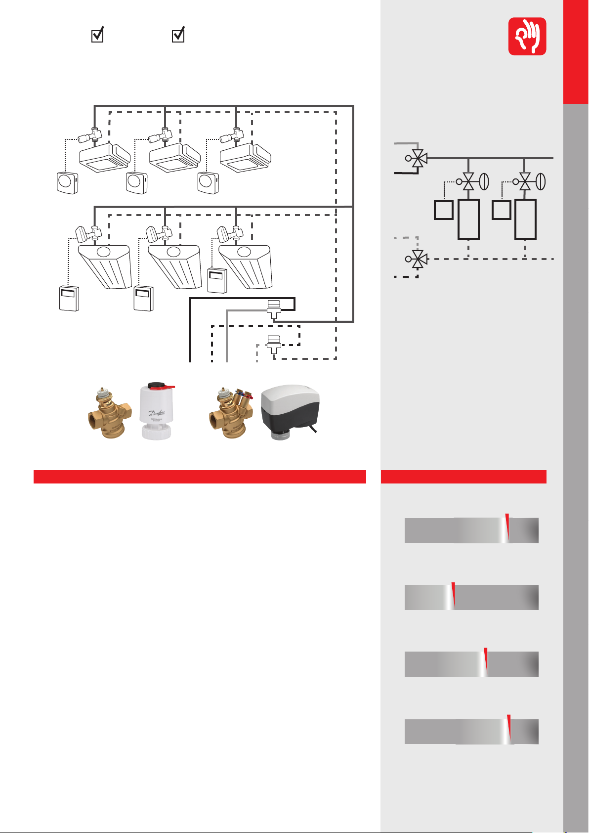
2.1 Mixing with PICV – manifold with pressure dierence 31
2.2 Injection (constant ow) control with 3-way valve 32
2.3 Mixing with 3-way valve – manifold without pressure dierence 33
3 AHU applications
3.1 AHU applications - heating
3.1.1 Pressure Independent Control (PICV) for cooling 34
3.1.2 3-way valve control for cooling 35
3.2 AHU applications - cooling
3.2.1 Pressure Independent Control (PICV) for heating 36
3.2.2 3-way valve control for heating 37
3.2.3 Keep proper ow temperature in front of AHU in partial load condition 38
4. Chillers applications
4.1 Variable primary ow 39
4.2 Constant primary variable secondary (Step Primary) 40
4.3 Constant primary and variable secondary (Primary Secondary) 41
4.4 Constant primary & secondary (Constant Flow System) 42
4.5 District cooling system 43
5. Boiler applications
5.1 Condensing boiler, variable primary ow 44
5.2 Traditional boilers, variable primary ow 45
5.3 System with manifolds de-couplers 46
6. Domestic hot water
6.1 Thermal balancing in DHW circulation (vertical arrangement) 47
6.2 Thermal balancing in DHW circulation (horizontal loop) 48
6.3 Thermal balancing in DHW circulation with self–acting disinfection 49
6.4 Thermal balancing in DHW circulation with electronic desinfection 50
6.5 DHW* circulation control with manual balancing 51
7. Glossary and abbreviations 54
8. Control and valve theory 56
9. Energy eciency analyses 65
10. Product overview 75
Page 6
Commercial
Hydronic applications
Residential
Hydronic applications
Mixing loop
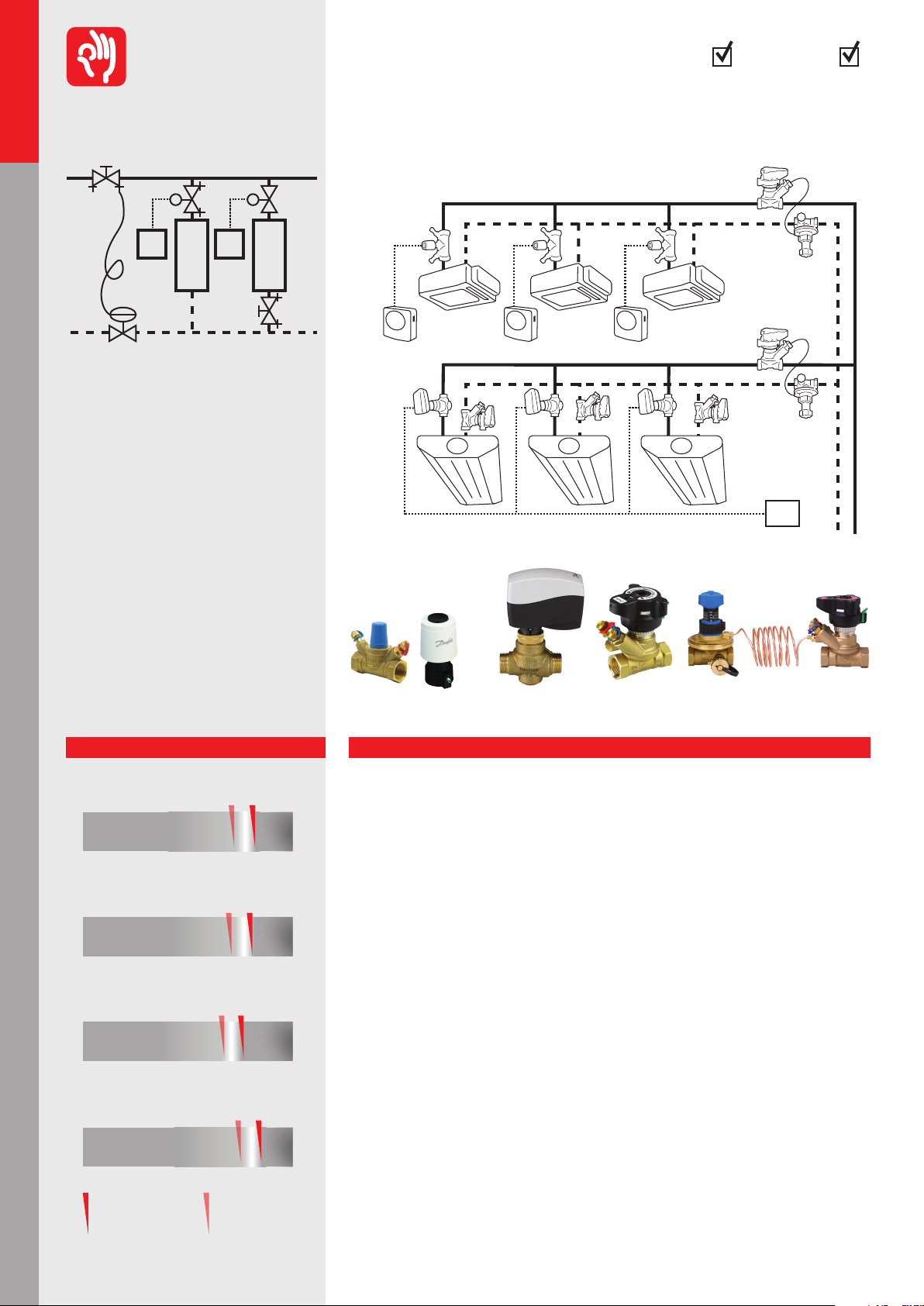
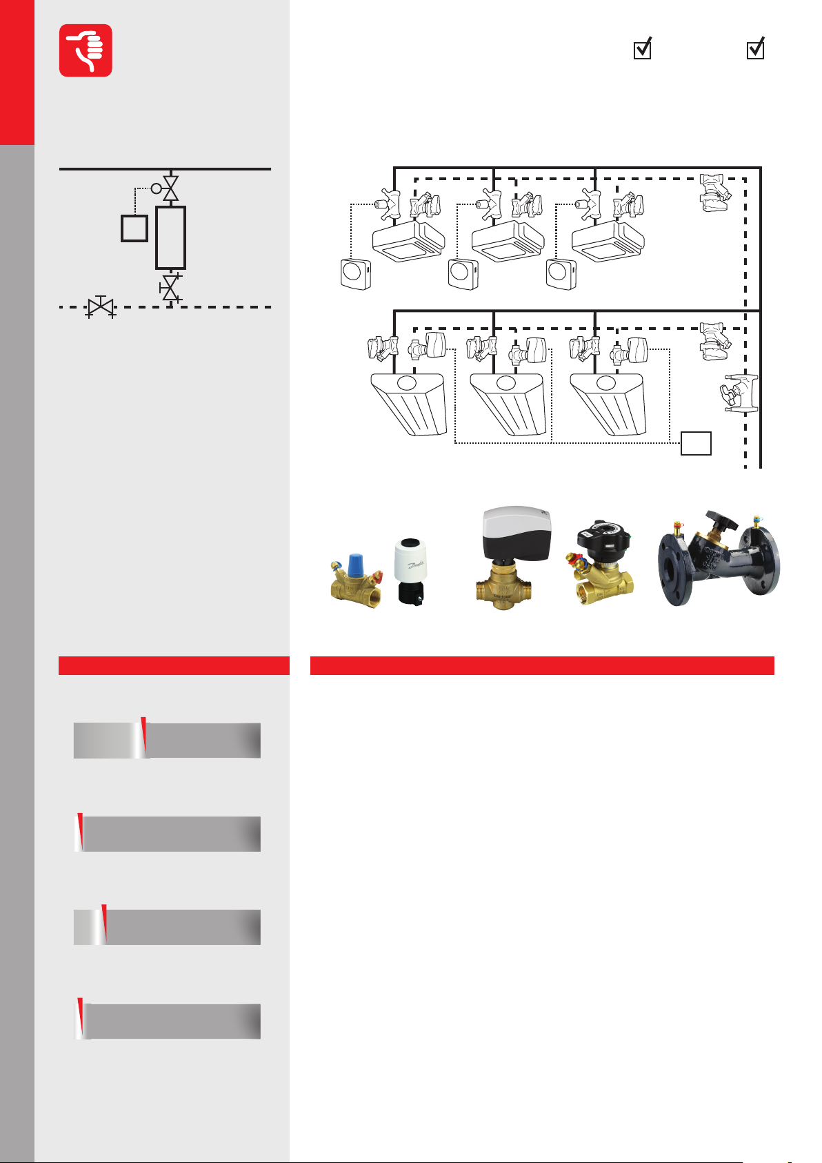
Hydronic applications – commercial buildings
Variable flow* systems
1.1.1.1 - 1.1.1.6**
Hydronic applications can be controlled and balanced based on a lot of dierent type of
solutions. It is impossible to nd the best one for all.
We have to take into consideration each system and its specic to decide what kind of solution will be the most ecient and suitable.
All applications with control valves are variable ow* systems. Calculation is generally done
based on nominal parameters but during operation ow in each part of the system is changing (control valves are working). Flow changes result in pressure changes. That’s why in
such case we have to use balancing solution that allows to respond to changes in partial load.
Pressure
Independent
Control
Notes
AHU application
AHU application
Chillers applicationsBoilers applicationsHot water
AHU heating
Dierential
Pressure
Control
AHU cooling
Manual
Balancing
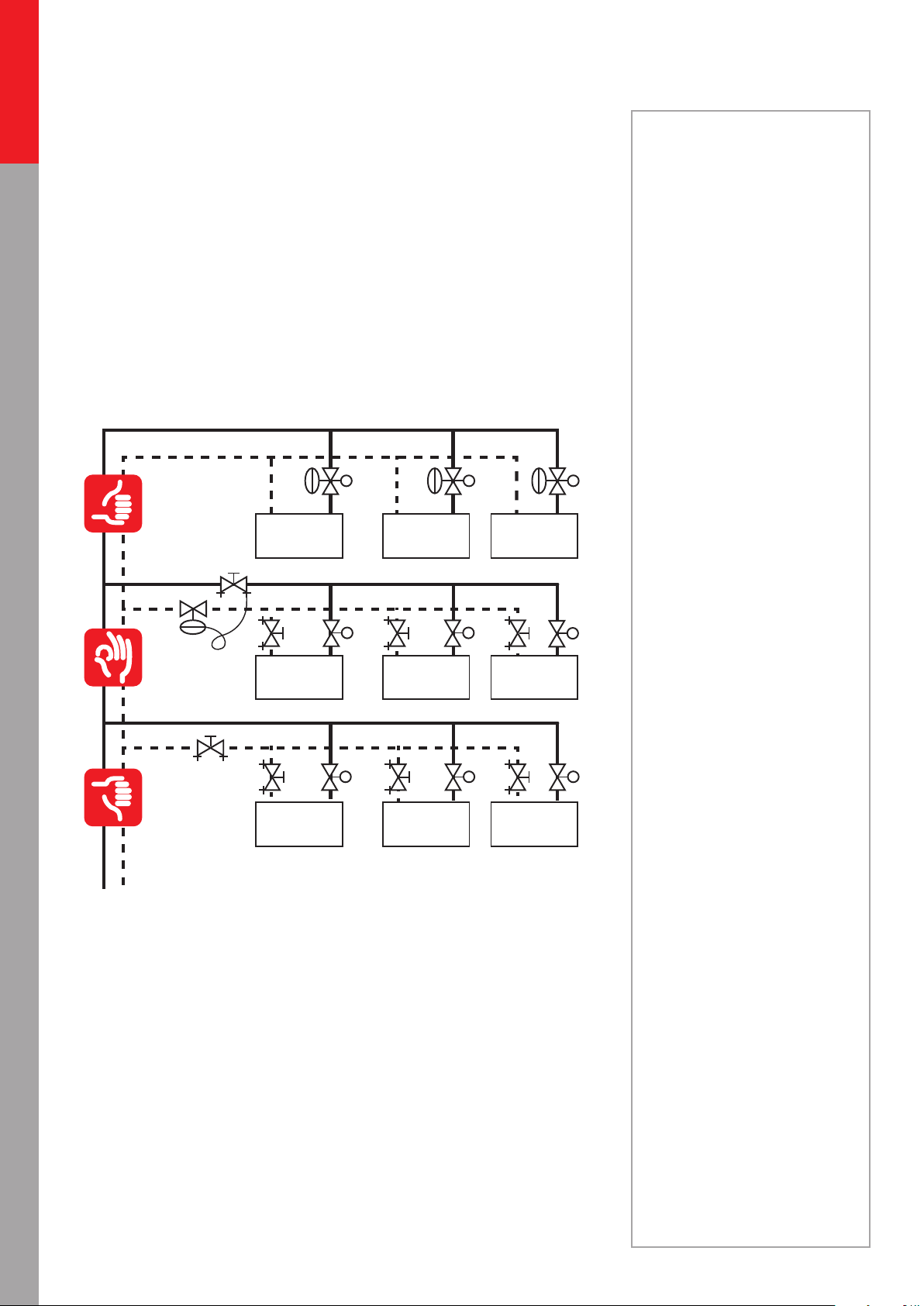
The evaluation of systems (Recommended/Acceptable/Not recommended) is principally
based on combination of 4 aspects mentioned on page 3 (Return on investment/Design/
Operation-Maintenance/Control) but the most important factors are the system performance and eciency.
On application above the manual balanced system is Not recommended because the static
elements are not able to follow the dynamic behaviour of variable ow* system and during
partial load condition huge overow occurs on control valves (due to smaller pressure drop
on pipe network).
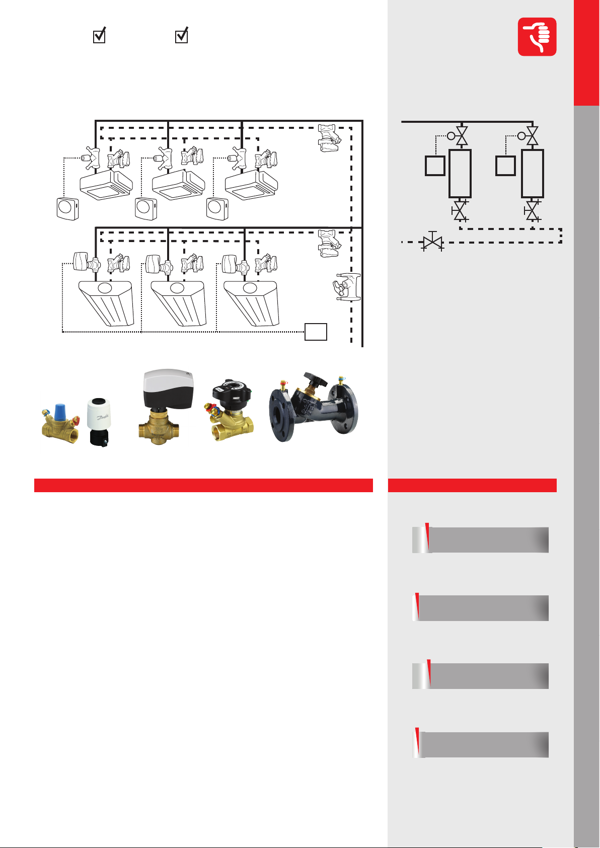
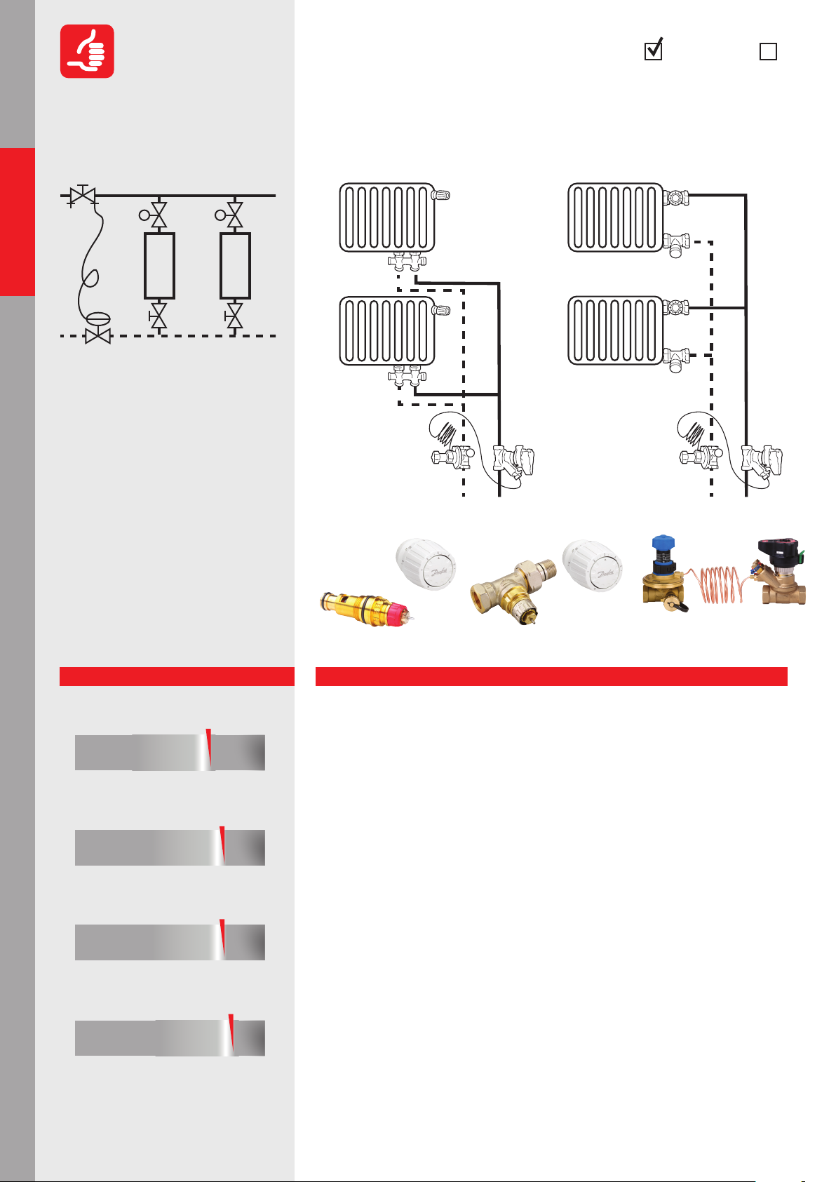
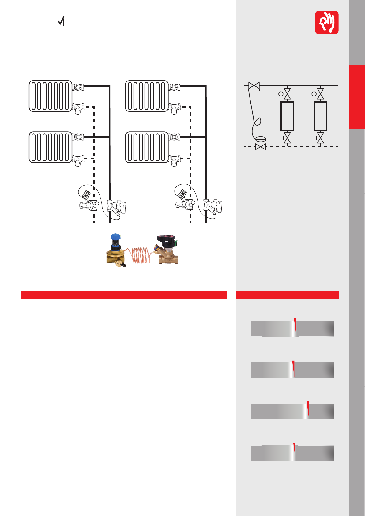
The dierential pressure controlled system performs much better (Acceptable) because
the pressure stabilization is closer to control valves and although we still have manual balanced system inside the dp controlled loop, the overow phenomenon mitigated. The
eciency of such system depends on location of dierential pressure control valve. The
closer it is to control valve, the better it works.
The most ecient (Recommended) system we can have is using PICV (pressure independent control valves). In this case the pressure stabilization is right on the control valve,
therefore we have full authority* and we are able to eliminate all unnecessary ow from
the system.
*see page 54-55
6
** applications below
Page 7
Commercial
Hydronic applications
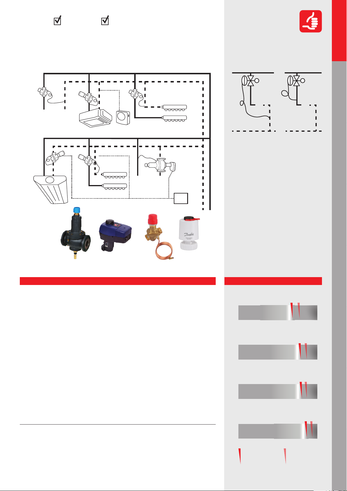
Hydronic applications – commercial buildings
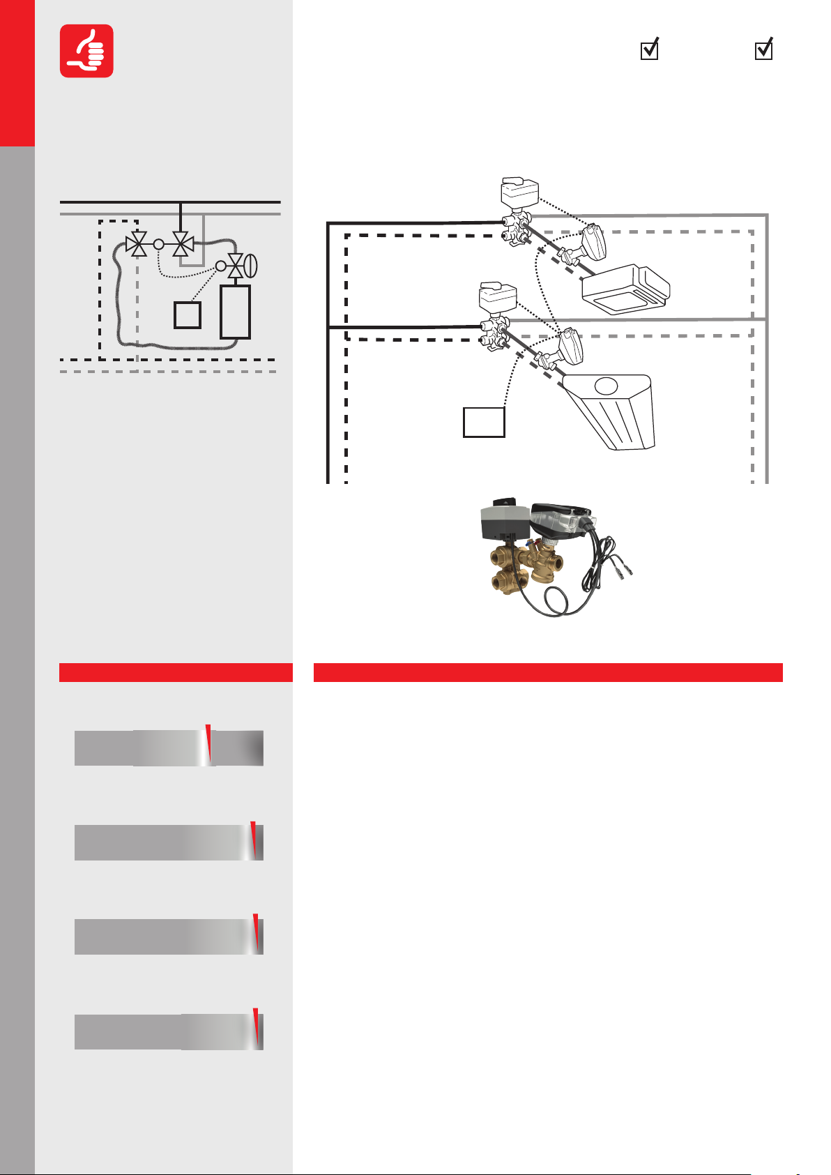
Variable flow* system: PICV – ON/OFF vs modulating vs smart control
1.1.1.1 - 1.1.1.3**
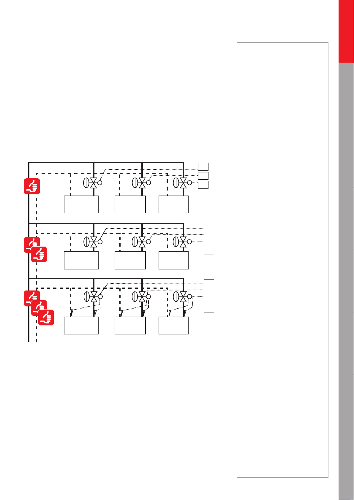
All these applications base on PICV (Pressure Independent Control Valve) technology. It
means the control valve (integrated into the valve body) is independent from pressure uctuation in the system during both full, and partial load conditions. This solution allows us to
use dierent types of actuators (control method)
• With ON/OFF control, the actuator has two positions, open and closed
• With modulation control the actuator is able to set any ow between nominal and zero
value
• With SMART actuator we can ensure (above modulation control) direct connectivity to
BMS (Building Management System) to use advanced functions such as energy allocation, energy management etc.
Controlers
Notes
Hydronic applications
Residential
Mixing loop
AHU application
AHU heating
PICV & ON/OFFPICV &
ControlerControler
modulating
T
PICV technology allows us to use proportional or end point (based on Δp sensor) pump
control
The above mentioned control types strongly aect on overall energy consumption of systems.
While ON/OFF control ensures either 100% or 0 ow during operation, the modulation
control enables to minimize the ow rate through on terminal unit according real demand.
For example, to the same 50% average energy demand we need around 1/3 of ow rate to
modulation control, compared to ON/OFF control. (You can nd more details in chapter 9)
The lower ow rate contributes to energy saving* on more levels:
• Less circulation cost (fewer ow needs less electricity)
• Improved chiller/boiler eciency (less ow ensures bigger ΔT in the system)
• Smaller room temperature oscillation* ensures better comfort and denes the room
temperature setpoint
T
PICV &
T
SMART actuator
T T
T
AHU application
AHU cooling
Chillers applications Boilers applications Hot water
The SMART control – over the above mentioned benets - enable to reduce the maintenance cost with remote access and predictive maintenance.
*see page 54-55
** applications below
7
Page 8
Commercial
FAN COIL UNITS (FCU)
Hydronic applications
Recommended
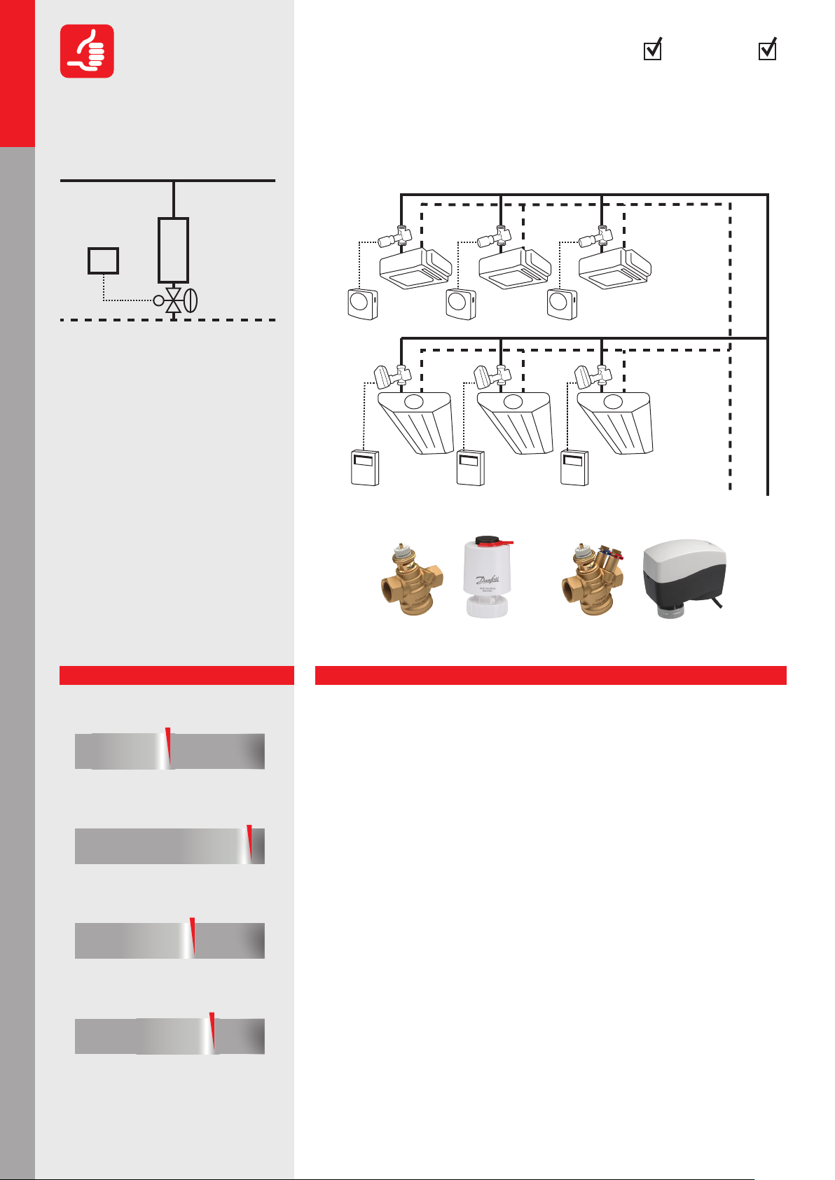
1.1.1.1
CoolingHeating
Variable ow: Pressure Independent Control
(PICV) with ON/OFF actuator
Residential
Hydronic applications
Mixing loop
AHU cooling
AHU applications
2
1
1. Preasure Independent
Control Valve (PICV)
2. Room temperature Control (RC)
Balancing of the terminal unit by pressure
independent valves. This will ensure the
right ow at all system loads, regardless
of pressure uctuations. ON/OFF control
will cause uctuations in the room
temperature. The system will not be
operating optimally because the ΔT
is not optimized.
PICV-1
RC
CHILLED PANELS
PICV-2
RC
Danfoss products:
AHU heating
AHU applications
Chillers applicationsBoilers applicationsHot water
Performance
Return of investment
poor acceptable
Design
poor
Operation/Maintenance
poor
Control
poor
acceptable
acceptable
acceptable
excellent
excellent
excellent
excellent
PICV-1: AB-QM 4.0 + TWA-Q PICV-2: AB-QM 4.0 + AMI-140
Explanation
Return of investment
• Reduction of components by eliminating the need for balancing valves
• Lower installation cost due to simplied installation
• The chillers and boilers operate eciently but not optimally because the ∆T is not
optimized
• Handover of the building can easily be done in phases
Design
• Easy selection of valves based only on the ow requirement
• No Kv or authority* calculation is needed, the calculation is based on ow demand
• Perfect balance at all loads
• Proportional pump control is applicable and the pump(s) can be optimized* easily
• Min available ∆p demand on the valve can be taken for calculating the pump head
Operation/Maintenance
• Simplied construction because of a reduction of components
• Set and forget, so no complicated balancing procedures
• Fluctuating room temperature, so some occupant complaints can be expected
• Low operational and upkeep cost, so occupants may experience discomfort
• Good but reduced eciency in chillers, boilers and pumping
because of a sub-optimized ∆T in the system
Control
• Temperature uctuations *
• No overows*
• Pressure independent solution, so no pressure changes do not aect control circuits
• Low ∆T syndrome* is unlikely to happen
8
*see page 54-55
Page 9
CoolingHeating
FAN COIL UNITS (FCU)
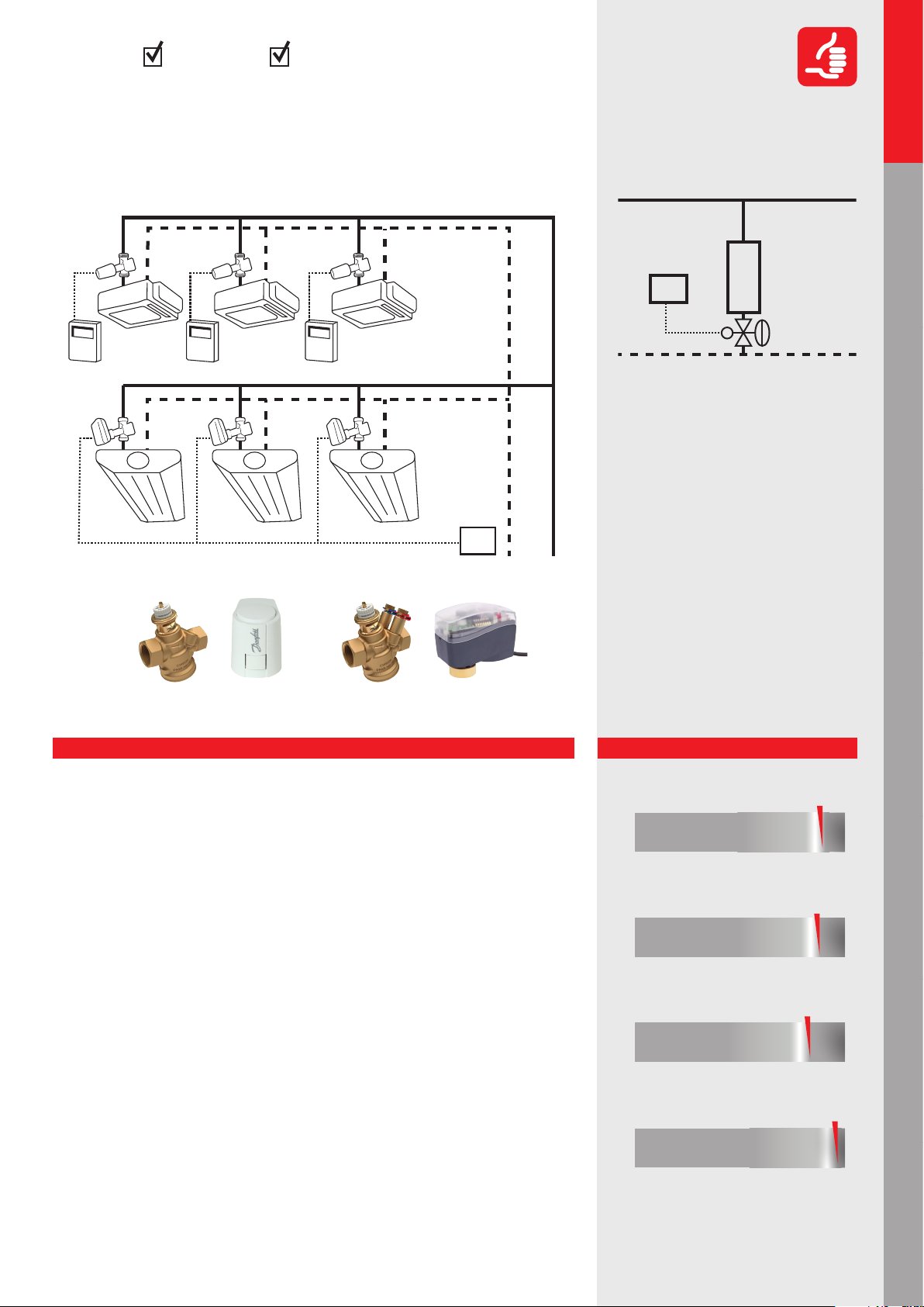
Variable ow: Pressure Independent Control
Hydronic applications
Commercial
Recommended
(PICV) with proportional control
PICV-1
0-10VRC
CHILLED PANELS
PICV-2
Danfoss products:
BMS
1.1.1.2
2
1
1. Pressure Independent
Control Valve (PICV)
2. Building Management System (BMS)
or Room temperature Control (RC)
Temperature control of the terminal unit
is ensured with pressure independent
valves. This will ensure the right ow at
all system loads, regardless of pressure
uctuations. The result will be stable*
and precise room temperature control to
ensure a high ΔT and prevent actuators
from hunting.
Hydronic applications
Residential
Mixing loop
AHU applications
AHU cooling
PICV-2: AB-QM 4.0 + AME 110 NLPICV-1: AB-QM 4.0 + ABNM A5
Explanation
Return of investment
• Reduction of components by eliminating the need for balancing valves
• Lower installation cost due to simplied installation
• Signicant energy savings* due to optimal working conditions for all components
• Handover of the building can easily be done in phases
Design
• Easy selection of valves based only on the ow requirement
• No Kv or authority* calculation is needed, ow presetting calculation based on ow
demand
• Proportional pump control is applicable. The pump(s) can be optimized easily *
• Suitable for BMS applications to monitor the system and reduce energy usage
Operation/Maintenance
• Simplied construction because of a reduction of components
• Set and forget, so no complicated balancing procedures
• Good control at all loads, so no complaints by occupants
• Low operational and upkeep cost
• High comfort (building classication*) because of precise ow control at all loads
• High eciency in chillers, boilers and pumping because of the optimized ∆T in the
system
Control
• Perfect control because of full authority *
• No overows* at partial system loads
• Proportional control minimizes the ow circulation and optimizes the pump head
• Pressure independent solution, so pressure interdependency of the control circuits
• No low ∆T syndrome *
Applicable for all terminal units, included
AHU (see page 34, 36)
Performance
Return of investment
poor
Design
poor
Operation/Maintenance
poor
Control
poor
acceptable
acceptable
acceptable
acceptable
excellent
excellent
excellent
excellent
AHU heating
Chillers applications Boilers applications Hot water
AHU applications
*see page 54-55
9
Page 10
Commercial
Hydronic applications
Residential
Hydronic applications
Recommended
1.1.1.3
3
I/O
2
BMS
CoolingHeating
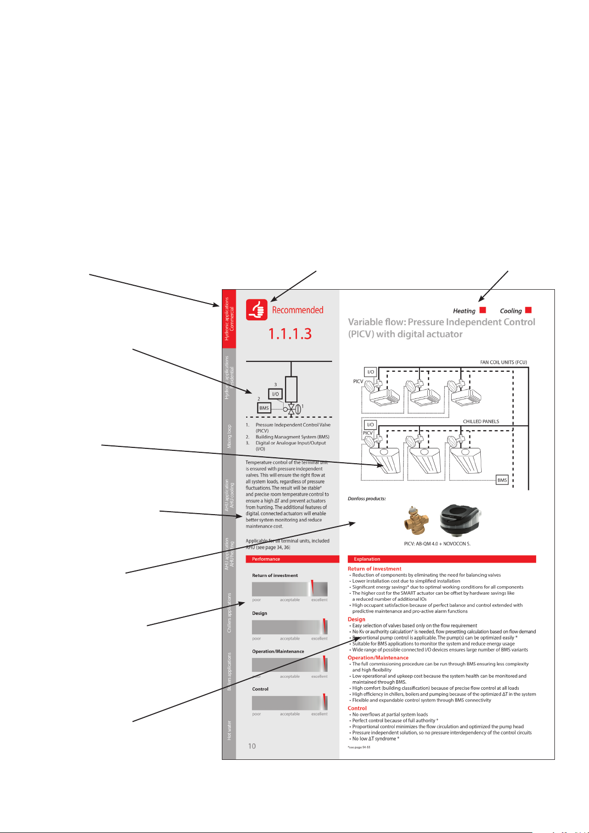
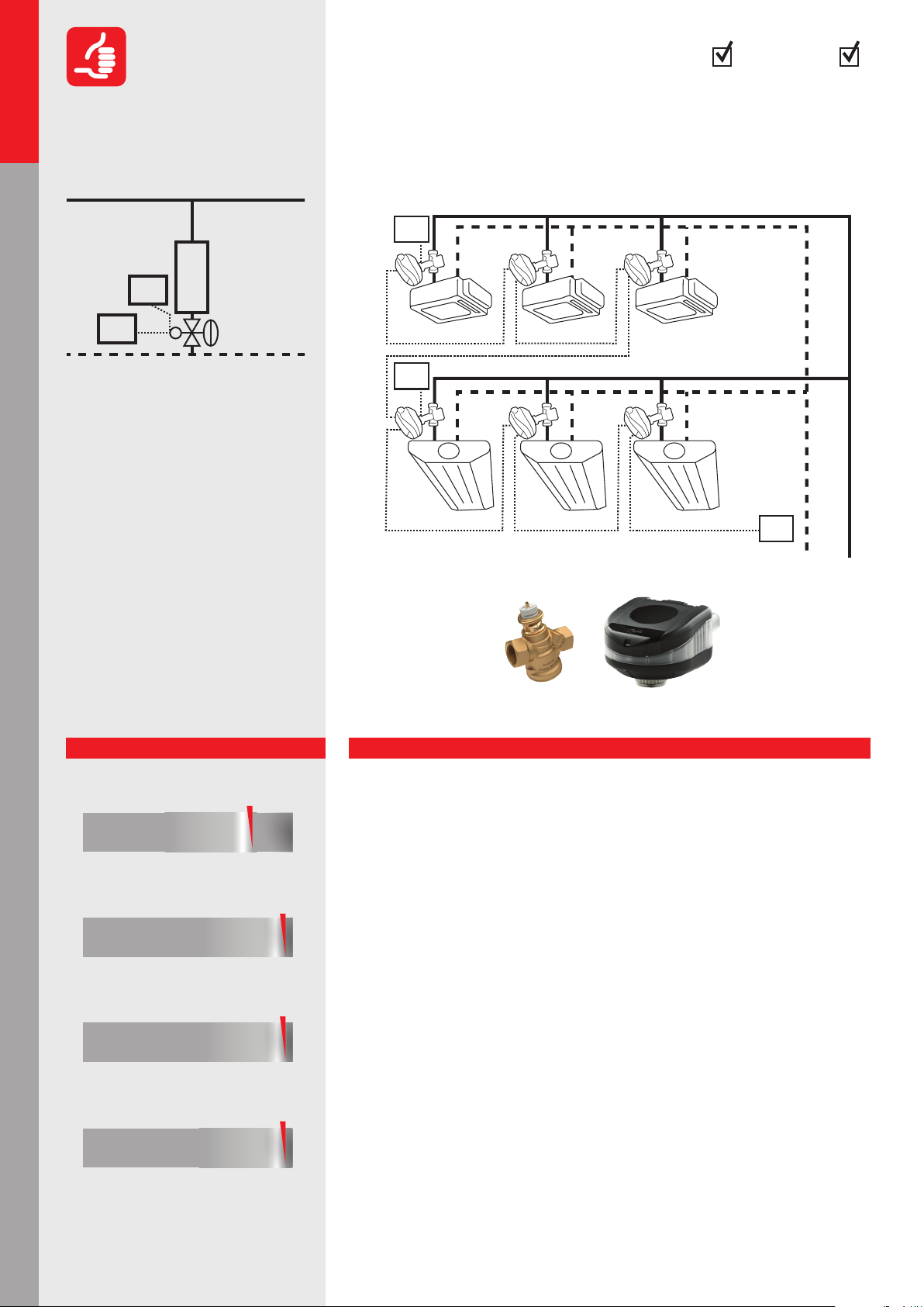
Variable ow: Pressure Independent Control
(PICV) with digital actuator
FAN COIL UNITS (FCU)
I/O
PICV
1
Mixing loop
AHU cooling
AHU applications
AHU heating
AHU applications
Chillers applicationsBoilers applicationsHot water
1. Pressure Independent Control Valve
(PICV)
2. Building Management System (BMS)
3. Digital or Analogue Input/Output
(I/O)
Temperature control of the terminal unit
is ensured with pressure independent
valves. This will ensure the right ow at
all system loads, regardless of pressure
uctuations. The result will be stable
and precise room temperature control to
ensure a high ΔT and prevent actuators
from hunting. The additional features of
digital, connected actuators will enable
better system monitoring and reduce
maintenance cost.
Applicable for all terminal units, included
AHU (see page 34, 36)
Performance
Return of investment
poor
Design
poor
Operation/Maintenance
poor
Control
poor
acceptable
acceptable
acceptable
acceptable
excellent
excellent
excellent
excellent
10
I/O
PICV
Danfoss products:
PICV: AB-QM 4.0 + NovoCon® S.
Explanation
CHILLED PANELS
BMS
Return of investment
• Reduction of components by eliminating the need for balancing valves
• Lower installation cost due to simplied installation
• Signicant energy savings* due to optimal working conditions for all components
• The higher cost for the SMART actuator can be oset by hardware savings like
a reduced number of additional IOs
• High occupant satisfaction because of perfect balance and control extended with
predictive maintenance and pro-active alarm functions
Design
• Easy selection of valves based only on the ow requirement
• No Kv or authority calculation* is needed, ow presetting calculation based on ow demand
• Proportional pump control is applicable. The pump(s) can be optimized easily *
• Suitable for BMS applications to monitor the system and reduce energy usage
• Wide range of possible connected I/O devices ensures large number of BMS variants
Operation/Maintenance
• The full commissioning procedure can be run through BMS ensuring less complexity
and high exibility
• Low operational and upkeep cost because the system health can be monitored and
maintained through BMS.
• High comfort (building classication) because of precise ow control at all loads
• High eciency in chillers, boilers and pumping because of the optimized ∆T in the system
• Flexible and expandable control system through BMS connectivity
Control
• No overows at partial system loads
• Perfect control because of full authority *
• Proportional control minimizes the ow circulation and optimizes the pump head
• Pressure independent solution, so pressure changes do not aect control circuits
• No low ∆T syndrome *
*see page 54-55
Page 11
CoolingHeating
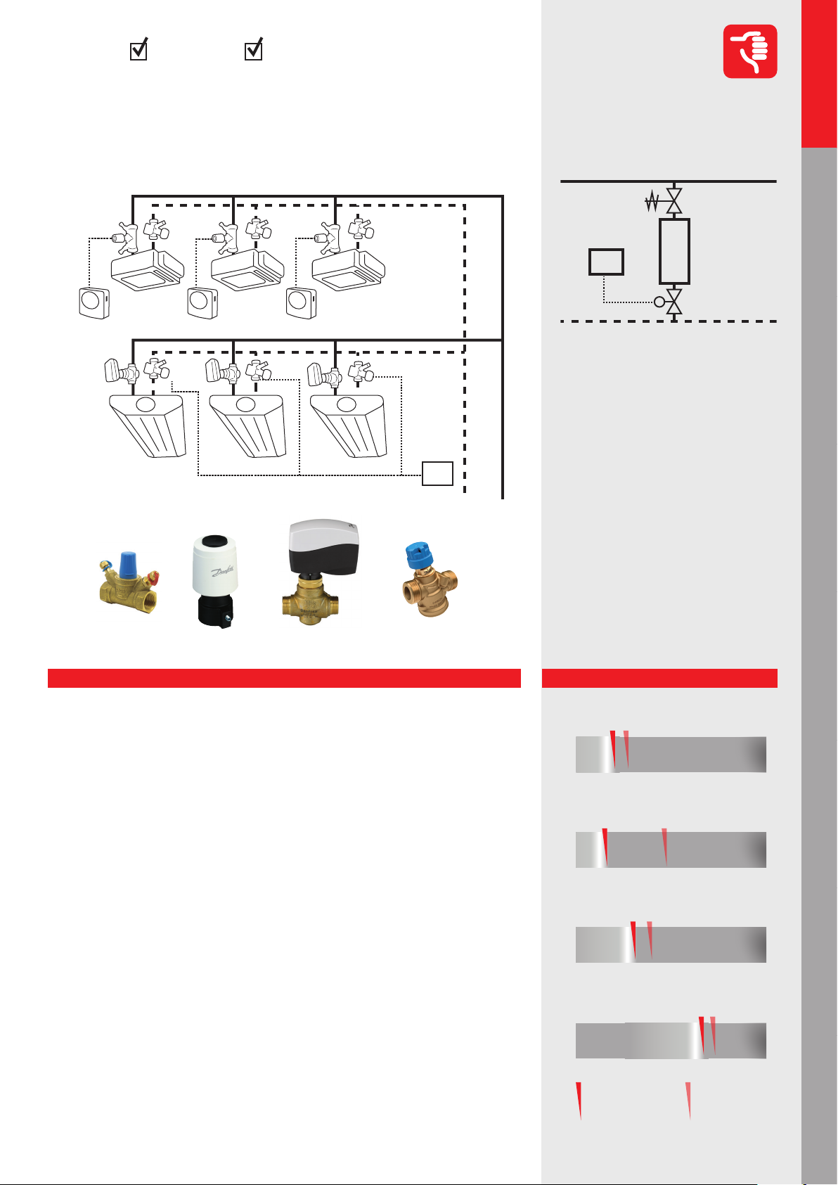
Variable ow: Flow limitation (with ow
Hydronic applications
Commercial
Not Recommended
limiter) on terminal unit with ON/OFF
or modular actuator
FAN COIL UNITS (FCU)
CV-1
ON/OFF
RC
CV-2
0-10V
Danfoss products:
FL
CHILLED PANELS
FL
BMS
CV-2: VZ2 + AME130 FL: AB-QMCV-1: RA-HC + TWA-A
1.1.1.4
2
3
1
1. 2-way Control Valve (CV)
2. Flow Limiter (FL)
3. Building Management System (BMS)
or Room temperature Control (RC)
Temperature control of the terminal unit
is done by conventional motorized control valves (CV) while the hydronic balance in the system is realized by automatic
ow limiter (FL). For ON/OFF control this
could be an acceptable solution, provided
that the pump head is not too high. For
modulating control this is not acceptable.
The FL will counteract the actions of the
CV and fully distort the control characteristic. Therefore, modulation with this
solutions is impossible.
Hydronic applications
Residential
Mixing loop
AHU applications
AHU cooling
AHU applications
AHU heating
Explanation
Return of investment
• Relatively high product cost because of 2 valves for all terminal units (one CV + FL)
• Higher installation costs although no manual partner valves* are needed
• Variable speed pump is recommended (proportional pump control is possible)
Design
• Traditional calculation is needed but only the kvs of the control valve. It is not necessary
to calculate the authority* since the FL will take away the authority of the CV
• For ON/OFF control it is an acceptable solution (simple design: big kvs of zone valve,
ow limiter selected based on ow demand)
• High pump head is needed because of the two valves (additional Δp on ow limiter)
Operation/Maintenance
• Closing force of actuator should be able to close the valve against the pump head at
minimum ow
• Most ow limiters have pre-determined ow, no adjustment is possible.
• For ushing cartridges need to be removed from the system and placed back
afterwards (emptying and lling the system twice)
• Cartridges have small openings and clog easily
• If modulation is attempted the lifetime of the CV is very short due to hunting at partial
system loads
• High energy consumption with modulation control due to higher pump head and
overow on terminal units in partial load
Control
• Temperature uctuations due to ON/OFF control, even with modulating actuators*
• No overows*
• No pressure interdependency of the control circuits
• Overow during partial load when modulating because the FL will keep the maximum
ow if possible
Performance
Return of investment
poor
Design
poor
Operation/Maintenance
poor
Control
poor
3-point or proportional control
acceptable
acceptable
acceptable
acceptable
Chillers applications Boilers applications Hot water
excellent
excellent
excellent
excellent
ON/OFF
control
*see page 54-55
11
Page 12
Commercial
Hydronic applications
Acceptable
1.1.1.5
CoolingHeating
Variable ow: Dierential pressure control
with ON/OFF or modulation
Residential
Hydronic applications
Mixing loop
AHU cooling
AHU applications
5
1. Zone Control Valve
(with presetting) (CV)
2. Zone Control Valve
(no presetting) (CV)
3. Manual Balancing Valve (MBV)
4. Δp Controller (DPCV)
5. Partner Valve*
6. Building Management System (BMS)
or Room temperature Control (RC)
1 2
6 6
4
3
Temperature control at the terminal unit is
done by conventional motorized control
valve (CV). Hydronic balance is achieved
by dierential pressure controllers (DPCV)
on the branches and manual balancing
valves (MBV) at the terminal unit. If the
CV has a pre-setting option the MBV is
redundant.
CV-1
ON/OFF
RC
CV-2
0-10V
Danfoss products:
FAN COIL UNITS (FCU)
DPCV
CHILLED PANELS
MBV
DPCV
BMS
AHU heating
AHU applications
Chillers applicationsBoilers applicationsHot water
It guarantees that, regardless of pressure
oscillations in the distribution network,
we have the right pressure and ow in the
pressure-controlled segment.
Performance
Return of investment
poor
Design
poor
Operation/Maintenance
poor
Control
poor
3-point or proportional control
acceptable
acceptable
acceptable
acceptable
excellent
excellent
excellent
excellent
ON/OFF
control
CV-2: VZ2 + AME130 DPCV: ASV-PV+ASV-BD MBV: MSV-BD CV-1: RA-HC +TWA-A
Explanation
Return of investment
• Requires Δp controllers and partner valves*.
• MBVs or pre-settable CV is needed for each terminal unit
• Cooling systems might require big and expensive (anged) Δp controllers
• Good energy eciency because there are only limited overows* in partial load
Design
• Simplied design because the branches are pressure independent
• Kv calculation needed for Δp controller and control valve. An authority* calculation is
also needed for modulating control
• Pre-setting calculation for terminal units is necessary for proper water distribution
within the branch
• The setting for the Δp controller needs to be calculated
• A variable speed pump is recommended
Operation/Maintenance
• More components to install included impulse tube connection between Δp - and partner valve*
• Simplied commissioning* procedure because of pressure independent branches
• Balancing on the terminal units is still required although simplied by Δp controlled branch
• Phased commissioning is possible (branch by branch)
Control
• Generally acceptable to good controllability
• Pressure uctuations that impact the controllability can occur with long branchesor
and/or big Δp on terminal units
• Depending on the size of the branch overows can still result in room temperature
uctuations.
• If we use ow limitation on partner valve* connected to Δp controller (not on terminal
units), higher overow and room temperature oscillation* are expected
12
*see page 54-55
Page 13
CoolingHeating
Variable ow: Shell and Core installation for
Hydronic applications
Commercial
Recommended
Oces and Shopping malls*
PICV-3
VACANT
Danfoss products:
PICV-1
?
PICV-3
PICV-2
PICV-3
RC
VACANT
FAN COIL UNITS (FCU)
CHILLED PANELS
PICV-1
?
BMS
1.1.1.6
1
?
1. Combined Automatic Balancing
Valve as Δp Controller (PICV 1)
2. Combined Automatic Balancing
Valve as Flow Controller (PICV 2)
This application is useful specically for
situations where the system is built in two
phases by dierent contractors. The rst
phase is usually the central infrastructure,
like boilers, chillers and transport piping,
while the second part includes the terminal units and room controls.
2
?
Hydronic applications
Residential
Mixing loop
AHU applications
AHU cooling
PICV-2 & PICV3: AB-PM + TWA-QPICV-1: AB-PM+AME435QM
Explanation
Return of investment
• Only one valve needed
• One actuator for zone or ow control
• Variable speed pump is recommended (proportional pump control is possible)
Design
• No kvs and authority* calculation needed.
• Presetting calculation needed only based on ow and Δp demand of loop
• For loop design (later stage of installation) the set parameters are available
Operation/Maintenance
• Reliable solution for shop or oor connection
• Flow setting can be done based on measurements on the test plugs of the valve
• Central distribution is always correctly balanced and independent of any mistakes
made in sizing on the occupant ‚s side
• Changes in secondary section of the system do not inuence other shops or oors
• Easy trouble shooting, energy allocation, management, etc. with NovoCon
Control
• Stable pressure dierence for shops or oors
• If only ow limitation is used small overows can happen within the loop during partial load
• Actuator on valve (if applied) ensures either zone control (Δp control application)
or ow control (ow control application)
This commonly occurs in shopping malls,
where the shops use their own contractor
to do the shop’s installation, or Shell &
Core oces where the renter of an oce
oor ts out his own space, including the
HVAC.
Performance
Return of investment
poor
Design
poor
Operation/Maintenance
poor
Control
acceptable
acceptable
acceptable
excellent
excellent
excellent
AHU heating
Chillers applications Boilers applications Hot water
AHU applications
**Two dierent approaches can be chosen:
1. Flow and ΔP limitation. Here the valve limits both the ΔP and the ow.
2. Flow limitation only. This will require additional zone controls and balancing
for the terminal units
*see page 54-55
poor
Δp control
application
acceptable
excellent
Flow control
application
13
Page 14
Commercial
FAN COIL UNITS (FCU)
Hydronic applications
Not Recomended
1.1.1.7
CoolingHeating
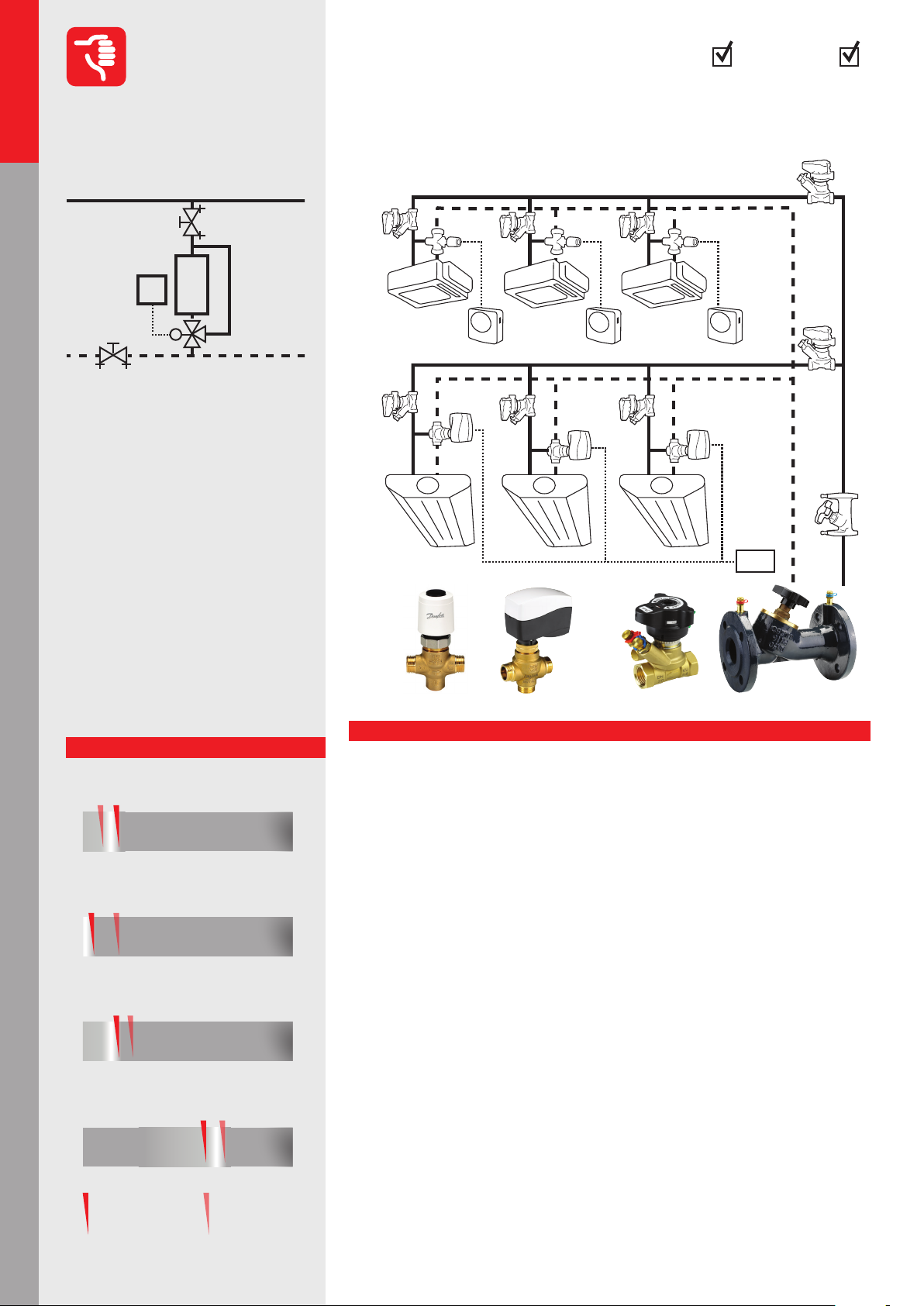
Variable ow: Manual balancing
Residential
Hydronic applications
Mixing loop
AHU cooling
AHU applications
AHU heating
AHU applications
Chillers applicationsBoilers applicationsHot water
1
4
3
1. 2-way Control Valve (CV)
2. Manual Balancing Valve (MBV)
3. Partner Valve* (MBV)
4. Building Management System (BMS)
or Room temperature Control (RC)
2
The terminal units are controlled by
conventional motorized control valves
and the hydronic balance is achieved by
manual balancing valve. Due to the static
nature the MBV only ensures hydronic
balance in full system load. During partial
load under- and overows can be expected in the terminal units, causing excessive energy consumption as well as cold
and hot spots in the system.
Performance
Return of investment
poor
Design
poor
Operation/Maintenance
poor
Control
poor
acceptable
acceptable
acceptable
acceptable
excellent
excellent
excellent
excellent
CV-1
RC
MBV-1
Danfoss products:
Explanation
MBV-1
MBV-1
CHILLED PANELS
CV-2 MBV-1
MBV-2
BMS
CV-2: VZ2 + AME130 MBV-1: MSV-BD MBV-2: MSV-F2 CV-1: RA-HC +TWA-A
Return of investment
• Many components are needed: 2 valves per terminal unit and additional branch valves
for commissioning*
• Increased installation cost due to many valves
• Complex commissioning procedure is required increasing risk of a delayed.
• Variable speed pump is recommended with constant Δp function
Design
• Precise sizing is required (Kv-value, authority*)
• Authority* calculations are crucial for acceptable modulation
• Constant Δp pump control is recommended because of the proper location
for the pressure
• It is impossible to predict system behaviour in partial load
Operation/Maintenance
• Complicated commissioning procedure that can only be executed by qualied sta
• Commissioning process can only be started at the end of the project with full load on
the system and sucient access to all balancing valves
• High complaint costs because of balancing issues, noise and inaccurate control during
partial load
• Rebalancing needed regularly and in case of changes in the system
• High pumping costs* because of overows during partial load
Control
• Interdependence of circuits creates pressure uctuations, which inuence control
stability and accuracy
• The generated overow reduces the system eciency (high pumping cost*, low ΔT
syndrome* in cooling system, room temperature oscillation*)
• Failure to create sucient pressure drop on the valve will result in low authority* which
will make modulating control impossible
14
*see page 54-55
Page 15
CoolingHeating
FAN COIL UNITS (FCU)
Variable ow: Manual balancing
Hydronic applications
Commercial
Not Recommended
with reverse return
CV-1
RC
CV-2
Danfoss products:
Explanation
MBV-1
MBV-1
CV-2: VZ2 + AME130 MBV-2: MSV-F2 MBV-1: MSV-BD CV-1: RA-HC +TWA-A
MBV-1
CHILLED PANELS
MBV-1
MBV-2
BMS
1.1.1.8
1
4 4
2
3
1. 2-way Control Valve (CV)
2. Manual Balancing Valve (MBV)
3. Partner Valve* (MBV)
4. Building Management System (BMS)
or Room temperature Control (RC)
In a reverse return system (Tichelmann),
the piping is designed in such way that
the rst terminal unit on the supply is the
last one on the return. The theory is that
all terminal units have the same available
Δp and therefore are balanced. This system can only be used if the terminal units
are the same size and have constant*
ow. For other systems this application is
unsuitable.
Performance
1
2
Hydronic applications
Residential
Mixing loop
AHU applications
AHU cooling
AHU applications
AHU heating
Return of investment
• Due to extra pipe runs the investment is much higher
• More space needed in technical shaft for additional third pipe
• Bigger pump needed because of added resistance of additional piping
• High complaint costs because of the balancing issues, noise and inaccurate control
during partial loads
Design
• Complicated piping design
• Precise control valve sizing is required (Kv-values, authority*)
• Authority* calculations are crucial for acceptable modulation
• Constant Δp pump control is recommended, it is impossible to use a Δp sensor
• The system is only balanced during full load conditions
• It is impossible to predict system behaviour in partial load
Operation/Maintenance
• Complicated commissioning* procedure that can only be executed by qualied sta
• Commissioning process can only be started at the end of the project with full load on
the system and sucient access to all balancing valves
• Δp sensor does not solve over pumping issues
• Rebalancing needed in case of changes in the system
• Extra high pumping costs* because of third pipeline and overows during partial load
Control
• Interdependence of circuits creates pressure uctuations which inuence control stability and accuracy
• The generated overow reduces the system eciency (high pumping cost*, low ΔT
syndrome* in cooling system, room temperature oscillation*)
• Failure in creating sucient pressure drop on the valve will result in low authority
which* will make modulating control impossible
Return of investment
poor
Design
poor
Operation/Maintenance
poor
Control
poor
acceptable
acceptable
acceptable
acceptable
Chillers applications Boilers applications Hot water
excellent
excellent
excellent
excellent
*see page 54-55
15
Page 16
Commercial
Hydronic applications
Recommended
1.1.1.9
CoolingHeating
Variable ow: Four-pipe Changeover (CO6)
for radiant heating/cooling panels, chilled
beams, etc. with PICV control valve
Residential
Hydronic applications
Mixing loop
AHU cooling
AHU applications
1
2
3
1. 6-way Valve
2. Pressure Independent
Control Valve (PICV)
3. Building Management System (BMS)
This application is useful if you have one
heat exchanger that needs to do both
heating and cooling. This t well with
radiant panel solutions. The application
uses a 6-way valve for switching over
between heating and cooling and a PICV
is used to balance and control the ow.
Danfoss products:
6-way value
FAN COIL UNITS (FCU)
PICV
6-way value
PICV
BMS
6-way valve + PICV: NovoCon ChangeOver6 +AB-QM
CHILLED PANELS
AHU heating
AHU applications
Chillers applicationsBoilers applicationsHot water
Performance
Return of investment
poor
Design
poor
Operation/Maintenance
poor
Control
poor
acceptable
acceptable
acceptable
acceptable
excellent
excellent
excellent
excellent
Explanation
Return of investment
• Only two valves are needed instead of four. One for changeover* and one for heating/
cooling control
• Very energy ecient thanks to high ∆T and no overows*
• Low commissioning* cost because only the ow needs to be set either on PICV or on
BMS when using a digital actuator
• BMS costs are reduced because only one datapoint is needed
Design
• Easy selection of PICV, only the ow is required for sizing
• No Kv or authority* calculations needed
• The Δp on CO6 valve does need to be checked
• Perfect balance and control under all loads ensuring precise room temperature control
Operation/Maintenance
• Simplied construction because of reduction of components and pre-built sets
• One valve controls both cooling and heating
• Low complaint costs because of perfect balance and perfect control at all loads
• No cross ow between heating and cooling
• Low operational and upkeep cost. Flushing, purging, energy allocation and management can all be done through BMS.
Control
• Perfect control because of full authority*
• Individual settings for cooling and heating (ow), so perfect control in both situations
• Precise room temperature control
• Digital actuator ensures further saving with energy measurement and management
function
16
*see page 54-55
Page 17
CoolingHeating
Variable ow: Two-pipe heating/cooling
Hydronic applications
Commercial
Acceptable
system with central changeover*
FAN COIL UNITS (FCU)
PICV-1
RC
CHILLED PANELS
PICV-2
RC
HEATING
SUPPLY/RETURN
Danfoss products:
PICV-1: AB-QM 4.0 + TWA-Q PICV-2: AB-QM 4.0 + AMI-140
SUPPLY
RETURN
COOLING
1.1.1.10
1
1
1. Central Changeover Valve
2. Pressure Independent
Control Valve (PICV)
3. Room thermostat (RC)
In this application a central change
guarantees that the rooms can be cooled
and heated. It is strongly recommended
to use a PICV to control the temperature
because of the dierent ow requirements for the heating and cooling.
2
3 3
Hydronic applications
Residential
2
Mixing loop
AHU applications
AHU cooling
AHU applications
AHU heating
Explanation
Return of investment
• Heavily reduced construction cost due to elimination of a secend set of pipes
• Extra costs if automatic changeover* is required
• Proportional pump control is recommended
Design
• Simple PICV selection according to cooling ow, which is usually the highest
• The change-over valve needs to be selected according to the biggest ow rate (cooling)
and a big Kvs is recommend to reduce the pumping cost*
• Dierent ow rates for heating and cooling need to be ensured, either by limiting the
actuator stroke or by the ability to remotely set the maximum ow, (digital actuator)
• In most cases a dierent pump head is needed for heating and cooling
Operation/Maintenance
• Simple system setup with few valves, so low maintenance cost
• The seasonal changeover* needs to be managed
• No overow* (if ow can be set for dierent heating/cooling mode)
Control
• Simultaneous heating and cooling in dierent rooms is not possible
• Perfect hydronic balancing and control with PICV
• ON/OFF control results in overows when the ow limitation is not solved for lower
ow demand (heating)
Performance
Return of investment
poor
Design
poor
Operation/Maintenance
poor
Control
poor
acceptable
acceptable
acceptable
acceptable
Chillers applications Boilers applications Hot water
excellent
excellent
excellent
excellent
*see page 54-55
17
Page 18
Commercial
Hydronic applications
Not Recommended
1.1.2.1
2
CoolingHeating
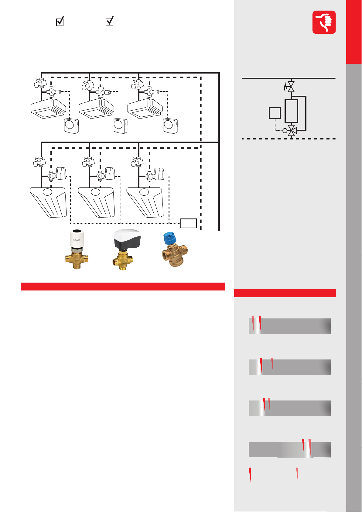
Constant ow: 3-way valve with manual balancing (in fan-coil, chilled beam etc. application)
FAN COIL UNITS (FCU)
MBV-1
CV-1
Residential
Hydronic applications
Mixing loop
AHU cooling
AHU applications
4
3
1. 3-way Control Valve (CV)
2. Manual Balancing Valve (MBV)
3. Partner Valve* (MBV)
4. Building Management System (BMS)
or Room temperature Control (RC)
1
In this application temperature control on
the terminal unit is done by using 3-way
valves. Manual balancing valves are used
to create hydronic balance in the system.
This application should be avoided due to
its high energy ineciency.
MBV-1
Danfoss products:
CV-2
RC
MBV-1
CHILLED PANELS
MBV-2
BMS
CV-2: VZ3 +AME130 MBV-2: MSV-F2CV-1: VZL3 + TWA-ZL
MBV-1: MSV-BD
AHU heating
AHU applications
Chillers applicationsBoilers applicationsHot water
Performance
Return of investment
poor
Design
poor
Operation/Maintenance
poor
Control
poor
acceptable
acceptable
acceptable
acceptable
excellent
excellent
excellent
excellent
Explanation
Return of investment
• Many components are needed: a 3-way valve and a balancing valve per terminal unit
and additional branch valves for commissioning*
• Extremely high operational cost, very energy inecient
• The ow is close to constant, no variable speed drive applied
• In partial loads very low ΔT in the system, so boilers and chillers run at very low eciency
Design
• Kv calculation is required, as well as an authority calculation* for the 3-way valve in case
of modulation
• A by-pass needs to be sized or a balancing valve should be tted. Otherwise big overows in partial loads can occur causing terminal unit starvation and energy ineciencies.
• For the Pump head calculation partial load needs to be considered if overows on the
by-pass are expected
Operation/Maintenance
• Commissioning of the system is required
• The hydronic balance at full- and partial load is acceptable
• Huge pump energy consumption due to constant operation
• High energy consumption (low ΔT)
Control
• The water distribution and the available pressure on the terminal units are more or less
constant under all loads
• The room temperature control is satisfactory
• An oversized control valve will result in low rangeability and oscillation* with modulation
18
ON/OFF
control
Modulation
control
*see page 54-55
Page 19
CoolingHeating
FAN COIL UNITS (FCU)
Constant ow: 3-way valve with ow limiter
Hydronic applications
Commercial
Not Recommended
on terminal units (fan-coil, chilled beam etc.
application)
FL
FL
Danfoss products:
CV-1
RC
CHILLED PANELS
CV-2
BMS
1.1.2.2
2
3
1
1. 3-way Control Valve (CV)
2. Flow Limiter (FL)
3. Building Management System (BMS)
or Room temperature Control (RC)
Hydronic applications
Residential
Mixing loop
AHU applications
AHU cooling
CV-2: VZ3 +AMV-130CV-1: VZL3 + TWA-ZL
Explanation
FL: AB-QM
Return of investment
• Many components are needed: a 3-way valve and an automatic ow limiter per terminal unit
• Fairly simple valve setup, no need for a balancing valve in by-pass or other valves for
commissioning*
• Extremely high operational cost, very energy inecient
• The ow close to constant, no variable speed drive applied
• In partial loads very low ΔT in the system, so boilers and chillers run at very low eciency
Design
• Kv calculation is required, as well as an authority* calculation for the 3-way valve in case
of modulation.
• Sizing and presetting of the ow limiters is based on the nominal ow of terminal unit
• For the Pump head calculation partial load needs to be considered if overows on the
by-pass are expected.
Operation/Maintenance
• Commissioning of the system is required
• The hydronic balance at full- and partial load is acceptable
• Huge pump energy consumption due to constant operation
• High energy consumption (low ΔT)
Control
• The water distribution and the available pressure on the terminal units are more or less
constant under all loads
• The room temperature control is satisfactory
• An oversized control valve will result in low rangeability and oscillation* with modulation
In this application temperature control on
the terminal unit is done by using 3-way
valves. Automatic ow limiters are used
to create hydronic balance in the system.
This application should be avoided due to
its high energy ineciency.
Performance
Return of investment
poor
Design
poor
Operation/Maintenance
poor
Control
poor
acceptable
acceptable
acceptable
acceptable
excellent
excellent
excellent
excellent
AHU heating
Chillers applications Boilers applications Hot water
AHU applications
*see page 54-55
ON/OFF
control
Modulation
control
19
Page 20
Commercial
Hydronic applications
Residential
Hydronic applications
Recommended
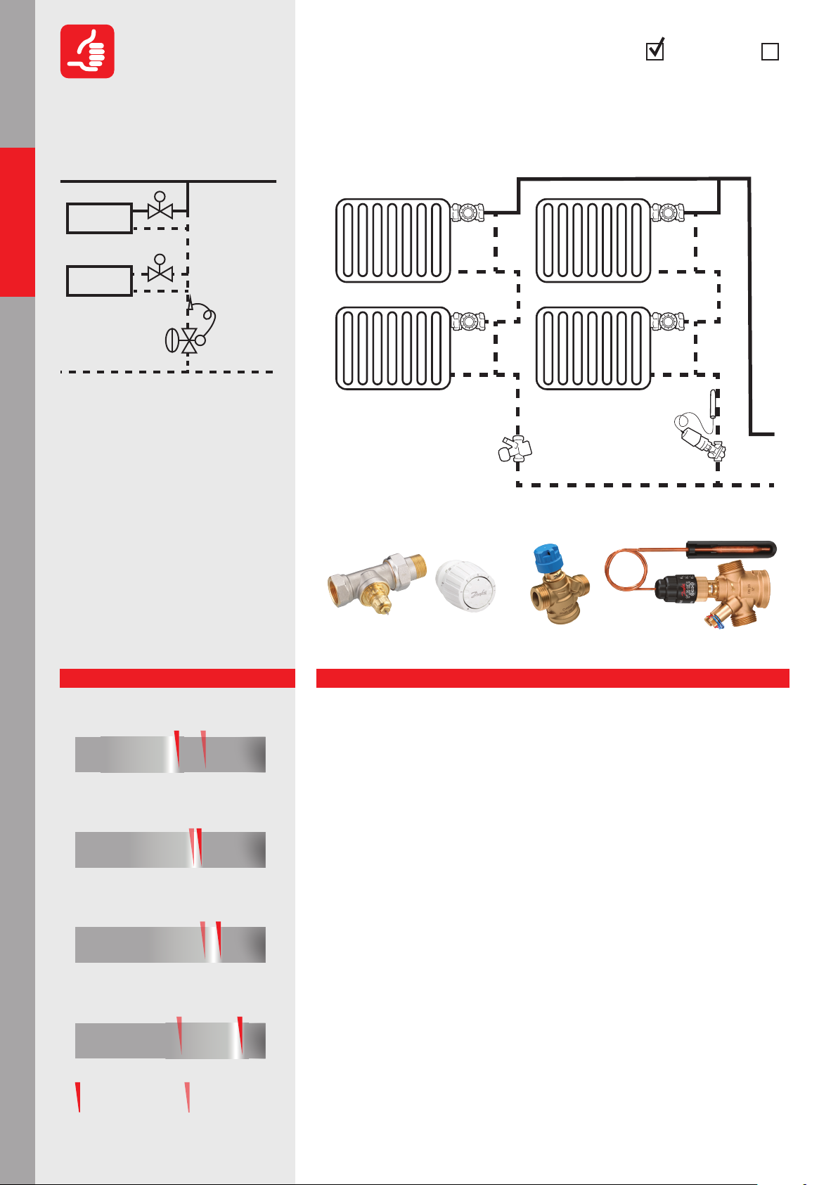
1.2.1.1
4
11
CoolingHeating
Two-pipe radiator heating system – risers
with, thermostatic radiator valves
(with presetting)
TRV-2
TRV-1
Mixing loop
AHU cooling
AHU applications
AHU heating
AHU applications
Chillers applicationsBoilers applicationsHot water
3
1. Termostatic Radiator Valve (TRV)
2. Return Locking Valve (RLV)
3. Δp controller (DPCV)
4. Partner valve*
In this application we ensure variable
ow* on risers with thermostatic radiator
valves. In case of presetting available
on TRV, ΔP controller used without ow
limitation on the riser.
Performance
Return of investment
poor
Design
poor
Operation/Maintenance
poor
Control
2 2
acceptable
acceptable
acceptable
excellent
excellent
excellent
DPCV
Danfoss products:
TRV-1: RA build in + RA TRV-2: RA-N + RA
Explanation
DPCV
DPCV: ASV-PV+ASV-BD
Return of investment
• Δp controller is more expensive compared to manual balancing
• Commissioning is not needed only Δp setting on Δp controller and ow pre-setting on TRVs
• Variable speed pump is recommended
Design
• Simple calculation method, Δp controlled risers can be calculated as independent loops
(you can split the system by risers)
• The presetting calculation of radiators is needed,
• Kv calculation needed for Δp controller and control valve. Authority calculation also
needed for proper TRV operation
• The Δp demand of loop should be calculated and set according nominal ow and
system resistance
Operation/Maintenance
• Hydraulic regulation is in the bottom of risers and radiator presetting
• No hydronic interference among the risers
• Balancing at full and partial load – good – with TRV presetting
• Good eciency: increased ΔT on riser and variable speed pump ensures energy saving
Control
• The eciency of system good with individual presetting on radiators
• Low pumping costs – the ow rate of risers are limited.
• Maximum ΔT on risers
20
poor
acceptable
excellent
*see page 54-55
Page 21
CoolingHeating
TRV
Two pipe radiator heating system – risers
Hydronic applications
Commercial
Acceptable
with, thermostatic radiator valves
(without presetting)
RLV-2
DPCV
1.2.1.2
Hydronic applications
Residential
4
11
3
2 2
Mixing loop
1. Termostatic Radiator Valve (TRV)
2. Return Locking Valve (RLV)
3. Δp controller (DPCV)
4. Partner valve*
AHU applications
AHU cooling
Danfoss products:
DPCV: ASV-PV+ASV-BD
Explanation
Return of investment
• Δp controller plus ow limitation is more expensive then manual balancing
• Commissioning* is needed for ow limitation on the bottom of riser plus dp setting on
Δp controller
• Variable speed pump is recommended
Design
• Simple calculation method, Δp controlled risers can be calculated as independent loops
(you can split the system by risers)
• The presetting calculation of partner valve* for ow limitation is required
• Kv calculation needed for Δp controller and control valve. Authority *checking is also
essential to know the control performance of TRV
• The Δp demand of loop should be calculated and set according nominal ow and
system resistance
Operation/Maintenance
• Hydronic regulation is at the bottom of risers only
• No hydronic interference among the risers
• Balancing at full and partial load is acceptable
• Acceptable eciency and variable speed pump ensures energy saving*
Control
• The ow limitation at the bottom of riser causes extra pressure drop within the Δp
controlled loop therefore higher overow appears during partial load (compared to
presetting on TRV )
• Higher pumping costs* – however the ow rate of risers is limited slight oveow occure
within the riser during partial load condition
• Acceptable ΔT on risers (lower comparing to presetting on TRV)
In this application we ensure variable*
ow on risers with thermostatic radiator
valves. No possibility of presetting on TRV,
ΔP controller used with ow limitation on
the riser with partner valve*.
Performance
Return of investment
poor
Design
poor
Operation/Maintenance
poor
Control
poor
acceptable
acceptable
acceptable
acceptable
excellent
excellent
excellent
excellent
AHU heating
Chillers applications Boilers applications Hot water
AHU applications
*see page 54-55
21
Page 22
Commercial
Hydronic applications
Recommended
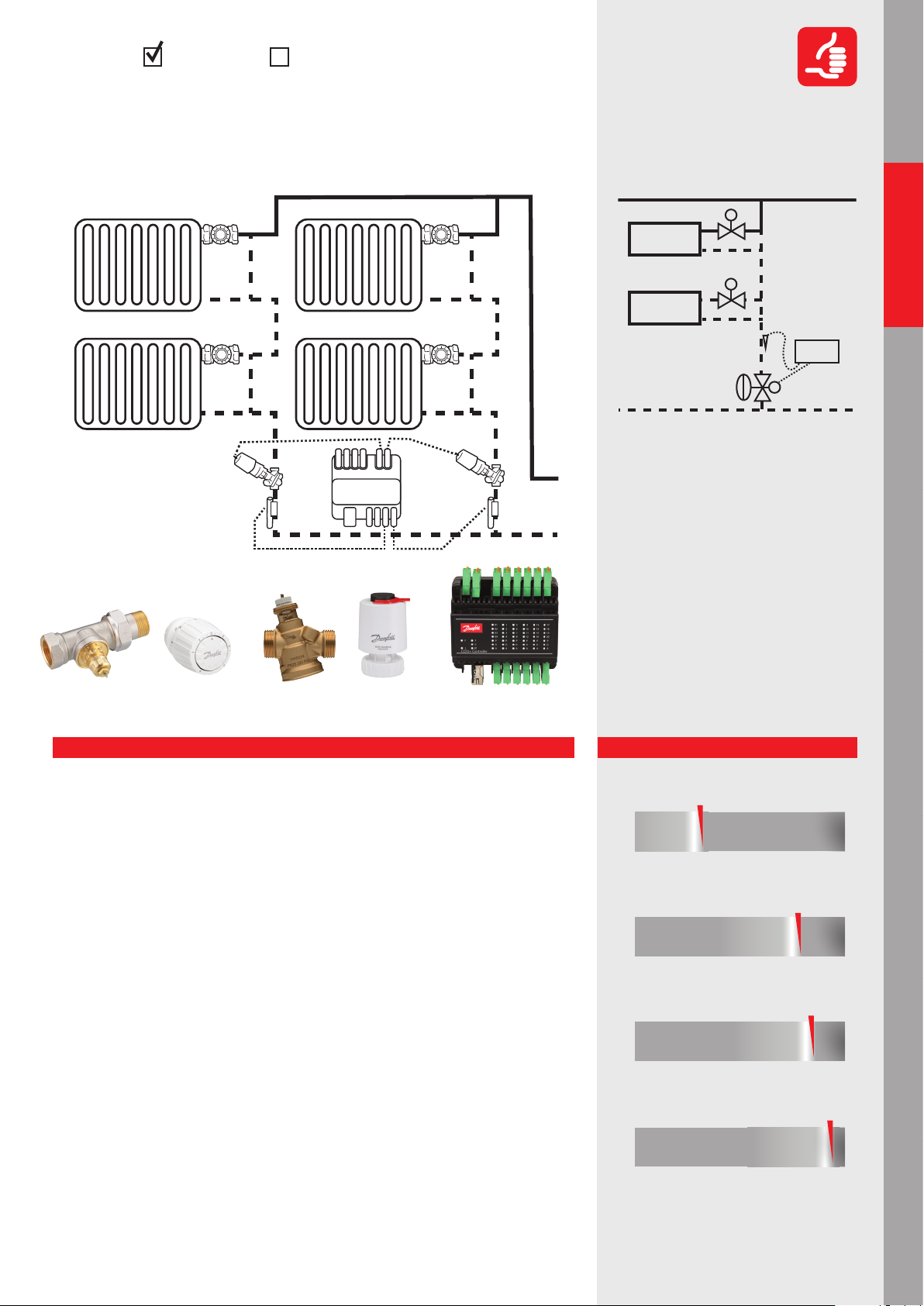
1.2.1.3
CoolingHeating
Pressure Independent Control for radiator
heating system
Residential
Hydronic applications
Mixing loop
AHU cooling
AHU applications
1
3 4
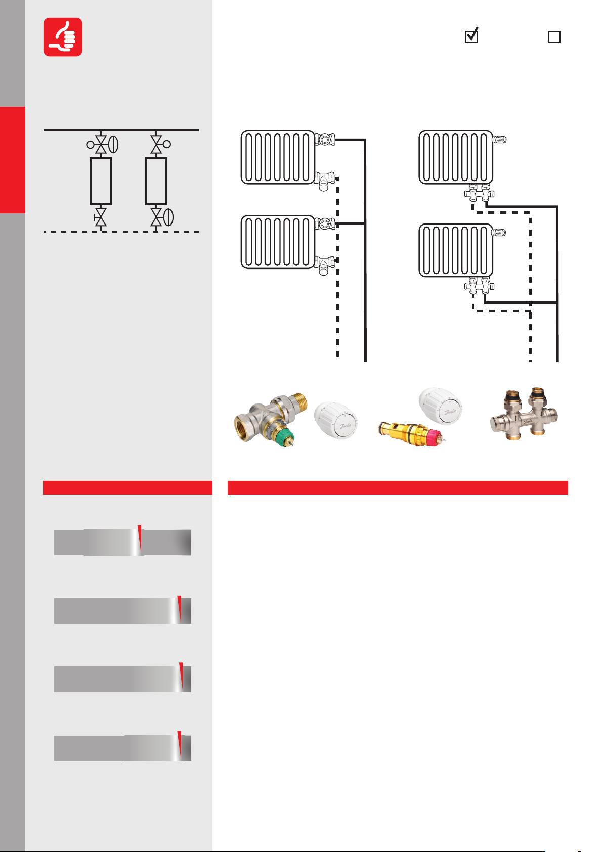
1. Radiator Dynamic Valve (RDV)
2. Termostatic Radiator Valve (TRV)
3. Return Locking Valve (RLV)
4. Return Locking
Dynamic Valve (RLDV)
In this application Pressure Independent
Control Valves used in smaller radiator heating system combined with thermostatic
senor (self-acting proportional room
temperature control), give us a guarantee
that regardless of the pressure oscillation
inside the system, we will secure the right
ow, allowing the right amount of heat
to be delivered to the room. (Traditional
radiator or „H” piece connection available).
2
Danfoss products:
RDV
TRV-1: RA build in + RA
TRV
RLDV
RLDV: RLV-KDVRDV: RA-DV + RA
AHU heating
AHU applications
Chillers applicationsBoilers applicationsHot water
Performance
Return of investment
poor
Design
poor
Operation/Maintenance
poor
Control
poor
acceptable
acceptable
acceptable
acceptable
excellent
excellent
excellent
excellent
Explanation
Return of investment
• A minimal number of components is needed which means less installation costs
• Low complaint costs because of perfect balance and perfect control at all loads
• Highly energy eciency because of precise ow limitation at all loads
• High eciency of boilers and pumping because of high ∆T in the system
Design
• Easy selection of valves based only on ow requirement
• No Kv or authority* calculation is needed, presetting calculation is based on ow demand
• Perfect balance and control at all loads
• Proportional pump control is recommended, pump speed can be optimized easily
• This solution applicable up to max. 135 l/h ow rate on terminal unit and max 60 kPa
pressure dierence across the valve
• Min available Δp on the valve 10 kPa
Operation/Maintenance
• Simplied construction because of reduction of components
• Set and forget, no complicated balancing procedures are needed
• Changes of ow setting do not inuence the other users
• Flow verication is possible on the valve with special tool
Control
• Perfect control because of full authority*
• No overows*
• Fix 2K proportional Xp band
• Fully pressure independent so no interference from pressure uctuations and therefore
stable room temperatures*
22
*see page 54-55
Page 23
CoolingHeating
Subordinated risers (staircase, bathroom,
Hydronic applications
Commercial
Recommended
etc.) in two- or one-pipe radiator heating
system without thermostatic valve
TRV
RLV
PICV
+QT
Danfoss products:
TRV: RA-N+RA PICV+QT: AB-QT
1.2.1.4
1
2
3
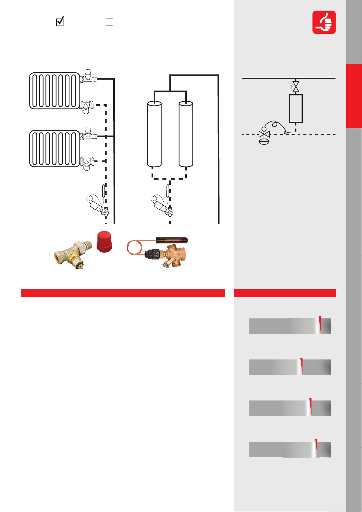
1. Radiator Valve (without sensor) (RV)
2. Pressure Independent Control Valve
(PICV)
3. Temperature Sensor (QT)
In this application we have theoretical
constant ow* on subordinated risers and
no thermostatic sensor on radiator valve
(like staircase, bathroom etc.) For better
eciency we ensure variable ow* in case
of partial load condition when the return
temperature is increasing, with return
ow temperature limitation.
Hydronic applications
Residential
Mixing loop
AHU applications
AHU cooling
AHU applications
AHU heating
Explanation
Return of investment
• QT (temperature limiter sensor) is an extra cost (ow limiter is recommended in any case)
• Commissioning of the system is not required only setting of ow on PICV and temperature on QT
• VSD pump is recommended
Design
• Simple calculation is required for riser ow, based on heat demand and ΔT, the size of
radiator, convector has to be designed accordingly
• The ow is controlled by return temperature signal
• The presetting calculation of radiator is crucial due to no room temperature controller,
the heat emission will depend on ow rate and size of radiator. The presetting calculation is based on ow rate among radiators and pressure drop of pipeline
• Simplied hydraulic calculation (you can split the system by risers)
Operation/Maintenance
• No overheating on riser during partial load condition (strongly recommended for
renovation)
• Good balancing at full and partial load - additional energy saving*
• Higher eciency, limited return temperature and variable speed pump ensures energy saving*
Control
• Inner rooms (typically bathrooms) have constant heat demand, to keep constant heat
output, with increasing ow temperature, QT reduces the ow rate.
• Less overheating of risers – energy saving*
• ΔT increasement ensures lower heat loss and better heat production eciency
• LOW pumping costs* – the ow rate of subordinated risers are limited and reduced
even more with temperature limitation by QT
• Limited eciency of QT control when ow temperature drops. Electronic controller
(CCR3+) increases eciency at higher outdoor temperature.
Performance
Return of investment
poor
Design
poor
Operation/Maintenance
poor
Control
poor
acceptable
acceptable
acceptable
acceptable
Chillers applications Boilers applications Hot water
excellent
excellent
excellent
excellent
*see page 54-55
23
Page 24
Commercial
Hydronic applications
Residential
Hydronic applications
Mixing loop
Recommended
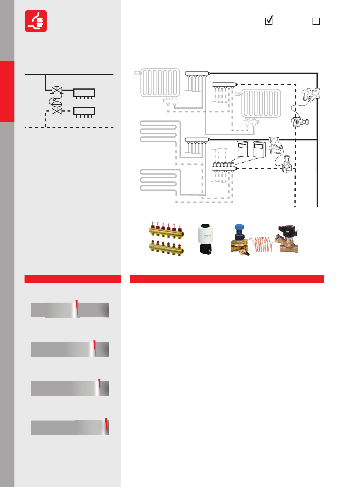
1.2.1.5
2
3
1
1. Δp controller (DPCV)
2. Partner valve*
3. Manifold with presettable valves
CoolingHeating
Δp control for manifold with individual
zone/loop control
RC
DPCV
AHU cooling
AHU applications
AHU heating
AHU applications
Chillers applicationsBoilers applicationsHot water
In this application we ensure variable
ow* in the distribution pipeline and
constant dierential pressure on each
manifold independently from temporal
load and pressure uctuation in the
system. Applicable for both radiator and
oor heating systems.
Performance
Return of investment
poor
Design
poor
Operation/Maintenance
poor
Control
poor
acceptable
acceptable
acceptable
acceptable
excellent
excellent
excellent
excellent
Danfoss products:
Manifold: FHF + TWA-A
Explanation
DPCV: ASV-PV + ASV-BD
Return of investment
• Beside manifold we need DPCV with partner valve*. Heat meter is often used for individual at connections
• Thermal actuator for zone control (oor heating) or thermostatic sensor (radiator)
• Commissioning is not needed, Δp setting and ow setting on manifold loops only
• With additional investment, the users’ comfort can be increased with individual, time
based wired or wireless room temperature control
• Variable speed pump is recommended
Design
• Simple DPCV sizing according kvs calculation and total ow demand of manifold
• Presetting calculation is needed for built in zone valves only
• The presetting of loops, limiting the ow to be ensured no under/overow on connections
Operation/Maintenance
• Reliable, pressure independent solution for individual at/manifold connection
• Partner valve* can have dierent functions like, impulse tube connection, shut o, etc.
• Flow setting can be done accurately via Δp setting on DPCV with heat meter
most often used
• NO noise risk thanks for Δp controlled manifolds
• High eciency, especially with individual programmable room control
Control
• Stable pressure dierence for manifolds
• Flow limitation is solved, no overow* or underow per connections
• Thermal actuators (oor heating) ensure manifold or individual time based room temperature zone control (ON/OFF) with suitable room controller
• Thermostatic sensor (radiator) ensures proportional room control with proper Xp band
24
*see page 54-55
Page 25
CoolingHeating
Δp control and ow limitation for manifold
Hydronic applications
Commercial
Recommended
with central zone control
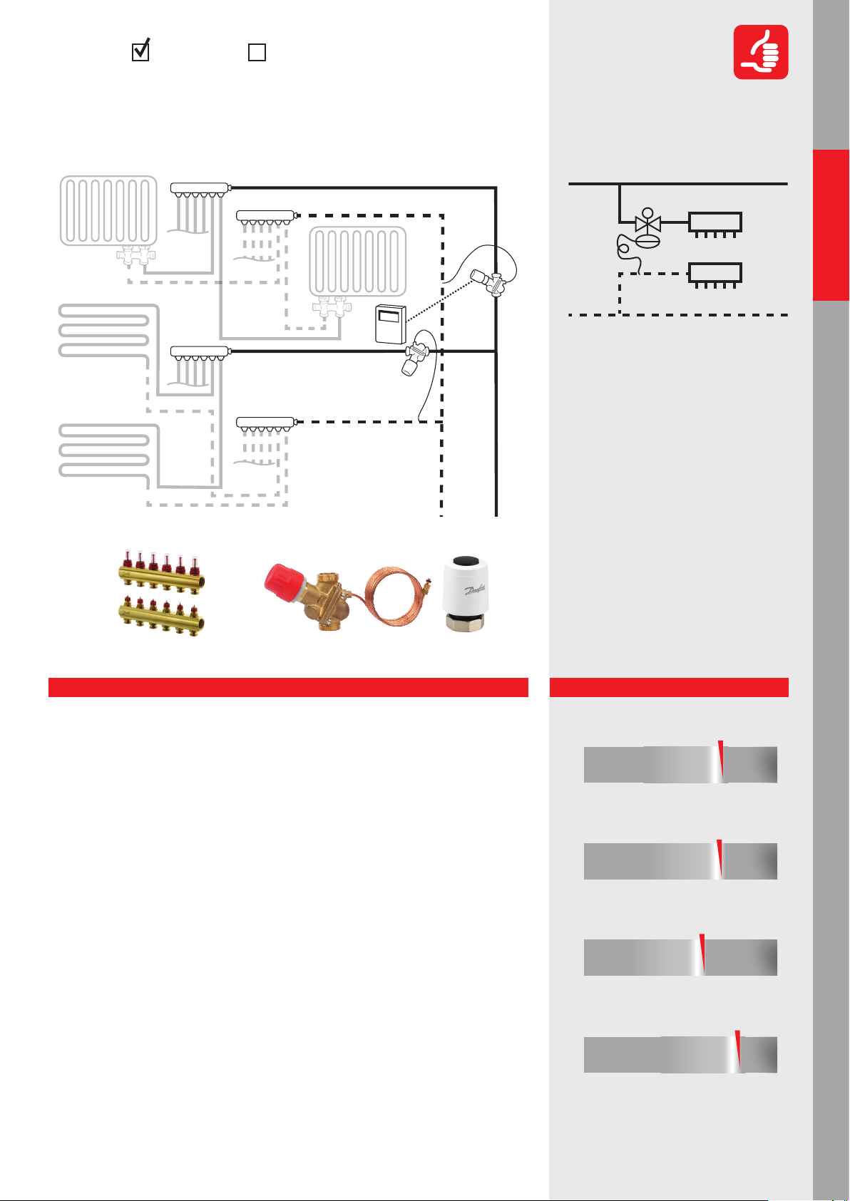
Danfoss products:
Manifold: FHF
DPCV
RC
ABV: AB-PM +TWA-Q (optional)
1.2.1.6
1
2
1. Δp controller (DPCV)
2. Manifold with presettable valves
In this application we ensure variable
ow* in the distribution pipeline and
maximum pressure dierence on each
manifold independently from temporal
load and pressure uctuation in the
system. Furthermore, we limit the ow for
manifold and able to ensure zone control
with adding thermal actuator on DPCV.
Applicable for both radiator and oor
heating systems.
Hydronic applications
Residential
Mixing loop
AHU applications
AHU cooling
AHU applications
AHU heating
Explanation
Return of investment
• DPCV and impulse tube connection needed only. Heat meter often used for individual
at connection
• Thermal actuator for zone control as option (installed on DPCV)
• Individual zone control (oor heating) or thermostatic sensor (radiator) also possible
• Installation time can be reduced with usage of set solution
• Commissioning is not needed, ow setting on DPCV only and presetting of each loop
• Variable speed pump is recommended
Design
• Simple, no kvs and authority* calculation, valve selection based on ow rate and Δp
demand of loop
• Presetting calculation is needed for built-in zone valves (if there are)
• The presetting of ow limitation ensures no under/overow on manifold
• Pump head calculation is very simple, min available pressure dierence for DPCV
(included the loop Δp) is given
Operation/Maintenance
• Reliable, pressure independent solution for individual at connection
• Partner valve* – if applied - can have dierent functions like, impulse tube connection,
shut o, etc.
• No noise risk thanks to Δp controlled manifold
• High eciency, especially with individual programmable room control
Control
• Maximized pressure dierence for manifold
• Flow limitation is solved, no overow* or underow per connections
• ...but slight overow within the loop during partial load
• Thermal actuator ensures zone control (ON/OFF) with suitable room controller
Performance
Return of investment
poor
Design
poor
Operation/Maintenance
poor
Control
poor
acceptable
acceptable
acceptable
acceptable
Chillers applications Boilers applications Hot water
excellent
excellent
excellent
excellent
*see page 54-55
25
Page 26
Commercial
Hydronic applications
Recommended
1.2.2.1
CoolingHeating
One-pipe radiator heating system renovation
with automatic ow limitation and possible
self-acting return temperature limitation
Residential
Hydronic applications
Mixing loop
AHU cooling
AHU applications
1
1
3
2
1. Radiator Valve (TRV )
2. Pressure Independent Control Valve
(PICV)
3. Optional - Temperature Sensor (QT)
This application is suitable for renovating
of vertical one-pipe radiator heating
system. We recommend high capacity
thermostatic radiator valve and ow
limiter installation on riser. For better
eciency we optionally recommend to
use return temperature control with QT
(Thermostatic Sensor)
Danfoss products:
TRV
PICV
PICV: AB-QM
PICV+QT
PICV+QT: AB-QTTRV: RA-G + RA
AHU heating
AHU applications
Chillers applicationsBoilers applicationsHot water
Performance
Return of investment
poor
Design
poor
Operation/Maintenance
poor
Control
poor
With QT Without QT
acceptable
acceptable
acceptable
acceptable
excellent
excellent
excellent
excellent
Explanation
Return of investment
• Investment cost are higher (thermostatic radiator valve + ow limiter + QT on risers)
compared to manual balancing
• Simple QT installation with low extra cost
• No commissioning* demand only ow setting
• Variable speed pump is recommended (without QT the pump control is not needed)
Design
• „α” (radiator share) calculation with iteration
• Big capacity TRV is needed to increase the „α”
• Radiator size depends on ow temperature changes
• Gravitation eect should be taken into account
• Simple hydronic calculation regarding riser controller, selection based on ow rate but
we need to ensure the minimum available pressure on it
• QT setting depends on system conditions
Operation/Maintenance
• System less sensitive for gravitation eect due to ow limitation
• „α” (radiator share) sensitive for installation punctuality
• Real constant ow* without QT, variable ow* with QT
• QT contributes to energy saving* on pumping
• QT ensures more accurate heat cost allocation
Control
• Accurate and simple water distribution among risers
• Improved room temperature control
• The radiator heat emission depends on varying ow temperature
• Heat gain from pipe in the rooms aects the room temperature
• QT eect is limited in case of higher outdoor temperature
26
*see page 54-55
Page 27
CoolingHeating
One-pipe radiator heating system renovation
Hydronic applications
Commercial
Recommended
with electronic ow limitation and return
temperature control
TRV
PICV
CCR3+
TS
1.2.2.2
1
1
4
2
1. Radiator Valve (TRV )
2. Pressure Independent Control Valve
(PICV)
3. Elecrtonic Controller (CCR3+)
4. Temperature sensor (TS)
3
CCR3+
Hydronic applications
Residential
Mixing loop
AHU applications
AHU cooling
Danfoss products:
TRV: RA-G + RA
Explanation
PICV: AB-QM+TWA-Q CCR3+
Return of investment
• High investment cost (thermostatic radiator valve + ow limiter with thermal actuator,
sensor on risers + CCR3+)
• Electronic wiring is needed, programing CCR3+
• No commissioning* demand only ow setting
• Variable speed pump is recommended
Design
• „α” (radiator share) calculation with iteration
• Big capacity TRV is needed to increase the „α”
• Radiator size depends on ow temperature changes
• Gravitation eect should be taken into account
• Simple hydronic calculation regarding riser controller, selection based on ow rate but
we need to ensure the minimum available pressure on it
• Dening of needed return characteristic
Operation/Maintenance
• The system less sensitive for gravitation eect due to ow limitation
• „α” (radiator share) sensitive for installation punctuality
• Programming CCR3+, data logging, remote maintenance and access
• Higher eciency due to improved ΔT, and reduced pipe heat loss
Control
• Accurate and simple water distribution among risers
• Improved room temperature control
• The radiator heat emission depends on varying ow temperature
• Heat gain from pipe in the rooms aects the room temperature
• CCR3+ Weather compensation on return temperature on all individual risers
This application is suitable for renovating
of vertical one-pipe radiator heating
system. We recommend high capacity
thermostatic radiator valve and ow limiter installation on riser. For best eciency
we recommend to use CCR3+ (Electronic
Controller)
Performance
Return of investment
poor
Design
poor
Operation/Maintenance
poor
Control
poor
acceptable
acceptable
acceptable
acceptable
excellent
excellent
excellent
excellent
AHU heating
Chillers applications Boilers applications Hot water
AHU applications
*see page 54-55
27
Page 28

Commercial
Hydronic applications
Not Recommended
1.2.2.3
CoolingHeating
One-pipe radiator heating system renovation with manual balancing
Residential
Hydronic applications
Mixing loop
AHU cooling
AHU applications
1
1
2
1. Radiator Valve (TRV )
2. Manual Balancing Valve (MBV)
This application is suitable for renovating
of vertical one-pipe radiator heating system. Many one-pipe system are renovated
based on thermostatic radiator valves and
manual balancing valves. It is not recommended due to its low eciency.
TRV
MBV
Danfoss products:
MBV: MSV-BDTRV: RA-G +RA
AHU heating
AHU applications
Chillers applicationsBoilers applicationsHot water
Performance
Return of investment
poor
Design
poor
Operation/Maintenance
poor
Control
poor
acceptable
acceptable
acceptable
acceptable
excellent
excellent
excellent
excellent
Explanation
Return of investment
• Medium investment cost (thermostatic radiator valve + manual balancing)
• Commissioning* is needed
• Complains can occur when not proper commissioning
• Traditional constant speed pump is acceptable
Design
• Dicult sizing of hydronic, presetting calculation of MBV is important
• „α” (radiator share) calculation with iteration
• Big capacity TRV is needed to increase the „α”
• Radiator size depends on ow temperature changes
• Gravitation eect should be taken into account
Operation/Maintenance
• System sensitive for gravitation eect (over/under pumping) during operation
• „α” (radiator share) sensitive for installation accuracy
• Not real constant ow*, the ow rate can vary 70-100% according to the radiator
valve operation
• High pumping energy consumption due to „constant” ow
• Inecient system, during partial load (when TRVs are closing) too high inlet temperature into radiators and overall return temperature
Control
• Inaccurate room temperature control
• The radiator heat emission depends on varying ow temperature
• Heat gain from pipe in the rooms aects the room temperature
• Inaccurate heat cost allocation
28
*see page 54-55
Page 29

CoolingHeating
One-pipe horizontal heating systems with
Hydronic applications
Commercial
Acceptable
thermostatic radiator valves, ow limitation
and return temperature self-acting control
TRV
PICV + QT
TRV
1.2.2.4
1
2
3
1. Radiator Valve (TRV )
2. Pressure Independent
Control Valve (PICV)
3. Temperature Sensor (QT)
Hydronic applications
Residential
Mixing loop
AHU applications
AHU cooling
Danfoss products:
TRV: RA-KE +RA
Explanation
PICV+QT: AB-QT
Return of investment
• Investment cost – good (thermostatic radiator valve + ow limiter + QT on risers)
• Less valves than in case of manual balancing, lower installation costs
• Simple QT installation and setting. (Re-set recommended based on operational experience)
• Commissioning* of the system not required (only ow and temperature setting)
• Variable speed pump is recommended
Design
• Traditional radiator connection. „a” (radiator share) eect on radiator selection
• Simplied hydraulic calculation, the loops are pressure independent
• No TRV presetting
• Return temperature setting on sensor of ow limiter according to system features
• Pump head calculation according to nominal ow and dp demand of ow limiter
• Heat metering applicable
Operation/Maintenance
• Minimal length of pipeline
• Higher pump head demand (vs. two pipe), due to minimum Δp on ow limiter, higher
pressure loss on pipeline, big Δp on radiator valve if no big Kvs selected
• The heat output of radiator depending on partial load condition due to varying inlet
temperature
• Optimization* of pump head is recommended (if variable pump control is available)
Control
• Thermostatic radiator valve has small Xp value
• Flow restriction in loop via QT when return temperature is increasing
• Loop ow demand is varying according to partial load condition
• Hydraulic regulation only at the end of loop, balancing at full and partial load – good
• Room temperature oscillation* occur s
In this application we ensure automatic
ow limitation for all heating circuits
and limit the return temperature with QT
(Thermostatic Sensor) to avoid small ∆T
in the loops during partial load. (More
ecient in case of lower outdoor temperature.)
Performance
Return of investment
poor
Design
poor
Operation/Maintenance
poor
Control
poor
acceptable
acceptable
acceptable
acceptable
excellent
excellent
excellent
excellent
AHU heating
Chillers applications Boilers applications Hot water
AHU applications
*see page 54-55
29
Page 30

1
Commercial
Hydronic applications
Recommended
1.2.3.1
Heating Cooling Water supply
Three-pipe, at station system; Δp controlled heating and local DHW* preparation
Residential
Hydronic applications
Mixing loop
AHU cooling
AHU applications
10
FLAT
STATION
5
4
2
1. Δp controller (DPCV)
2. Partner valve*
3. Heating return (primary)
4. Heating ow (primary)
5. Domestic Cold Water (DCW)
6. Heating return (secondary)
7. Heating ow (secondary)
8. Circulation (DHW-C)
9. Domestic Hot Water
10. Domestic Cold Water
In this application we use 3 pipes only
(heating ow / return and cold water ),
for heating of the ats and instantaneous
DHW* preparation locally (at the at). We
ensure variable ow*, Δp control for heating system and ow limitation on riser
taking into consideration the simultaneous eect
9
8
7
6
3
(primary)
(DHW) (secondary)
(DCW) (secondary)
Danfoss products:
DPCV
FLAT
STATION
FLAT
STATION
DPCV: ASV-PV + MSV-F2
Flat Station: Evoat
AHU heating
AHU applications
Chillers applicationsBoilers applicationsHot water
Performance
Return of investment
poor
Design
poor
Operation/Maintenance
poor
Control
poor
acceptable
acceptable
acceptable
acceptable
excellent
excellent
excellent
excellent
Explanation
Return of investment
• Investment cost are signicant (at stations, MBV in front of ats + Δp control in risers)
but they are worth to be considered taking into account the full investment cost
• Less pipeline and additional equipment (no primary DHW*system), less installation cost
• Commissioning *of MBV and setting of DPCV with ow limitation is needed
• Variable speed pump is recommended (constant pump characteristic)
Design
• Special hydraulic calculation is needed for pipeline: the size of pipeline depends on
simultaneous factor
• Presetting calculation for TRVs is needed
• Riser ∆p controller: ∆p setting (at station + pipeline) + ow limitation according simultaneous eect
• The at station is equipped with ∆p controller for heating
• Flat pump characteristic is advantage, fast reaction VSD* needed (due to very fast load
changes in the system based on DHW* uctuation)
Operation/Maintenance
• Δp controlled TRV ensures good room temperature control
• Heat losses on primary pipe are low (one hot pipe instead of two)
• Higher pump head demand – high ∆p demand on at station and extra pressure loss
on ∆p controller + ow limiter required
• Simple system setup, easy energy metering
• No legionella problem
Control
• Balancing at full and partial load very good
• Energy ecient solution, low heat loss in the system
• High comfort; TRV and/or time control possible
• Pressure independent DHW* preparation, ∆p controlled heating, ow limitation on riser
30
*see page 54-55
Page 31

CoolingHeating
Mixing with PICV – manifold
Hydronic applications
Commercial
Recommended
with pressure dierence
controller
Danfoss products:
TS
PUMP
PICV
2.1
2
3
1. Preasure Independent Control
Valve (PICV)
2. Temperature sensor (TS)
3. Controller
Regardless of pressure uctuations in the
system, we have the right ow for the
temperature control of the secondary
side. The PICV valve ensures the mixed/
controlled ow temperature circulated by
the secondary pump. The primary pump
ensures the needed pressure dierence
up to the mixing points including the Δp
demand of PICV.
1
Hydronic applications
Residential
Mixing loop
AHU applications
AHU cooling
PICV: AB-QM + AME435QM
Explanation
Return of investment
• Minimum number of components - no MBV needed
• Low installation cost
• Primary pumps needed to cover the Δp demand up to mixing points
• MBV is needed on the secondary side if there is no VSD* or pressure stabilization
• Balancing on secondary side is required
• VSD on primary side is recommended
Design
• Easy PICV selection based on ow requirement
• The PICV valve size can be smaller if the secondary temperature is lower than the primary temperature
• Perfect hydronic balance and control at all loads,
• Min available Δp demand on the valve should be taken for primary pump selection
• Proportional primary pump control can be used
Operation/Maintenance
• Simplied construction due to the a reduction of components
• No balancing needed, just setting the ow on the PICV
• Non-return valve is recommended in the by-pass line to prevent back-ow if the secondary pump stops
• Flexible solution; the ow rate setting does not inuence the other mixing loops
• Low operational and upkeep cost
Control
• Full authority* of control valve, precise control of secondary water temperature
• No overows*
• Pressure independent solution, no interference from pressure uctuations in the system
• Linear system response matches with linear PICV characteristic
• Room temperature oscillation* occur s
The individual terminal unit should be
controlled according to applications is
chapter 1 or 2. One possibility is shown in
the drawing.
Performance
Return of investment
poor acceptable
Design
poor
Operation/Maintenance
poor
Control
poor
acceptable
acceptable
acceptable
excellent
excellent
excellent
excellent
AHU heating
Chillers applications Boilers applications Hot water
AHU applications
*see page 54-55
31
Page 32

Commercial
Hydronic applications
Acceptable
2.2
CoolingHeating
Injection (constant ow) control
with 3-way valve
Residential
Hydronic applications
Mixing loop
AHU cooling
AHU applications
2
5
2
1. 3 - way Control Valve (CV)
2. Manual Balancing Valve (MBV)
3. Non-Return Valve (N-RV)
4. Temperature Sensor (TS)
5. Controller
The 3-way valve controls the ow to ensure the required temperature on the secondary side. The circulation pump and the
MBV on the secondary side are needed
to ensure mixing and (usually) a constant
ow* through the loop (for example with
radiant heating). A 3-way valve and MBV
are used in the primary circuit to ensure
proper temperature control for the loop
and balancing the circuits. It should only
be used in case of big temperature dierences between primary and secondary.
1
4
3
2
Danfoss products:
MBV
CV
controller
N-RV
MBV
CV: VF3 + AME435 MBV: MSV-F2
TS
MBV
AHU heating
AHU applications
Chillers applicationsBoilers applicationsHot water
Performance
Return of investment
poor acceptable
Design
poor
Operation/Maintenance
poor
Control
poor
acceptable
acceptable
acceptable
excellent
excellent
excellent
excellent
Explanation
Return of investment
• Very high: 3-way valve + 2xMBV for balancing and control (partner valve* for the pump
is needed for the pump head setting)
• More valves result in higher installation cost
• Both MBVs have to be balanced
• No VSD* required on the primary side because of constant ow*
Design
• The 3-way valve has good authority* because of the small pressure drop on the primary
network
• The 3-way valve should be sized accordingly to the ow rate of the primary side
• Kv and ow pre-setting calculation of the MBV is essential for the ow setting
• MBV is calculated based on the nominal condition and is valid for all system loads
Operation/Maintenance
• Complicated system setup with many valves and a lot of balancing
• Slight ow changes during partial load due to ideal authority* of the 3-way valve
• Simple balancing of the secondary MBV but complex balancing is needed on the primary side
• A non-return valve is recommended in the by-pass line to prevent back-ow if the
secondary pump stops
• In case of a low secondary energy demand the ΔT of the primary circuit will drop
• No possibility of energy saving* on the pump because of constant ow*
Control
• Good control thanks to high authority* of the control valve
• Constant ow, so no pressure oscillation. Therefore there is no interference among loops
• Low ΔT syndrome* in cooling
• Recommended only if the secondary ow temperature is signicantly lower than the
primary
32
*see page 54-55
Page 33

CoolingHeating
Mixing with 3-way valve – manifold
Hydronic applications
Commercial
Not Recommended
without pressure dierence
MBV
controller
Danfoss products:
MBV
TS
CV
2.3
4
2
5
2
3
1. 3 - way Control Valve (CV)
2. Manual Balancing Valve (MBV)
3. De-coupler
4. Temperature Sensor (TS)
5. Controller
The 3-way valve controls the ow temperature on the secondary side. This setup
allows dierent ow rates in the primary- and secondary loops. The secondary
pump circulates the water through the
system included manifolds and de-coupler. Primary pump is located before
de-coupler, there is no pressure dierence
between manifolds.
Hydronic applications
Residential
1
Mixing loop
AHU applications
AHU cooling
CV: VF3 + AME435 MBV: MSV-F2
Explanation
Return of investment
• 3-way valve and MBV are needed, more valves results in higher installation cost
• The balancing of the MBV is important
• The secondary side should be equipped with a variable speed drive (variable ow)
• Balancing of the secondary side is needed
• Primary pump control should be done by return temperature if possible, which results
in additional controller cost
Design
• Simple 3-way valve sizing (50% of the pump head should drop on the control valve)
• Linear 3-valve and actuator characteristic is needed
• Kv and pre-setting calculation for MBV are essential for compensating Δp dierences
between the by-pass line and the manifold loop towards de-coupler
• Secondary pump needs to cover the Δp demand from and to the de-coupler
Operation/Maintenance
• Complicated system setup with several valves and balancing of the MBVs is required
• For stable operation of the 3-way valve the authority* and rangeability need to be taken
into consideration
• If the primary pump is not controlled water will be circulated back needlessly during
partial load
• Low energy eciency due to low ΔT and high pump head demand on the primary pump
Control
• Good control if the authority* is 50% or higher *
• Very low overows* on the secondary side
• The mixing loops are pressure independent
• Low ΔT syndrome * primary pump is not properly controlled
• The linear system response is combined with a linear 3-way valve characteristic, so
temperature is stable control
The individual terminal unit should be
controlled according to applications in
chapter 1 or 2. One possibility is shown in
the drawing.
Performance
Return of investment
poor acceptable
Design
poor
Operation/Maintenance
poor
Control
poor
acceptable
acceptable
acceptable
excellent
excellent
excellent
excellent
AHU heating
Chillers applications Boilers applications Hot water
AHU applications
*see page 54-55
33
Page 34

1
-
Commercial
Hydronic applications
Residential
Hydronic applications
Recommended
3.1.1
1. Preasure Independent Control
Valve (PICV)
CoolingHeating
Pressure Independent Control (PICV)
for cooling
PICV
Mixing loop
AHU cooling
AHU applications
AHU heating
AHU applications
Chillers applicationsBoilers applicationsHot water
A PICV is used to control the AHU so that
regardless of pressure uctuations in the
system we secure the right ow.
It is applicable if Δp is available for PICV.
A by-pass is recommended to be used
in front of the PICV (light gray) to ensure
proper ow temperature in partial load
also, when there is no circulation in AHU
at all. Dierent types of by-pass control
can be used. (see page 38).
Performance
Return of investment
poor acceptable
Design
poor
Operation/Maintenance
poor
Control
poor
acceptable
acceptable
acceptable
excellent
excellent
excellent
excellent
MBV
Danfoss products:
PICV: AB-QM + AME345QM
Explanation
Return of investment
• A minimal number of components because there is no MBV on primary side and/or
partner valves* are needed. Consequently, there is a low installation cost
• Minimal complaint costs because of perfect balance at all loads
• No balancing* needed
• Energy ecient because of proper ∆T in the system
Design
• Easy selection of valves based only on the ow requirement
• No Kv or authority* calculation is needed. The ow pre-setting calculation is based
on the ow demand
• Perfect balance at all loads
• Proportional pump control is recommended.
• Minimum available Δp demand on the valve should be used to select the primary
pump
Operation/Maintenance
• Simplied construction because of a reduced number of components
• Set and forget, no complicated balancing procedures are needed for the primary side
• Low operational and upkeep cost
Control
• Perfect control thanks to full authority *
• No overows*
• Pressure independent solution, no interference from pressure uctuations anywhere
in the system
• No low ΔT syndrome *
• Stable temperature control without hunting of the valve
34
*see page 54-55
Page 35

CoolingHeating
3-way valve control for cooling
CV
Hydronic applications
Commercial
Not Recommended
3.1.2
Hydronic applications
Residential
-
2
1 2
MBV-2
MBV-1
Danfoss products:
MBV-1: MSV-F2 CV: VF3 + AME435
Explanation
Return of investment
• Many components are needed: a 3-way valve and 2*MBV, and additional partner valves
for commissioning* in bigger system
• Extremely high operational cost, very energy inecient
• The ow is close to constant, no VSD applied
• In partial loads very low ΔT in the system, so chillers run at very low eciency
Design
• Kvs calculation is required, as well as an authority calculation* for the 3-way valve
• Presetting of MBVs crucial for proper system operation and control
• The by-pass MBV needs to be calculated to compensate the pressure drop of terminal
unit, otherwise big overows occur in partial loads causing terminal unit starvation and
energy ineciency
• High (min. 1:100) control ratio is needed for proper low ow control on 3-way valve
Operation/Maintenance
• Commissioning of the system is required
• The hydronic balance at full and partial load is acceptable
• Huge pump energy consumption due to constant ow operation
• High energy consumption (low ΔT)
Control
• Good control in case of ~50% authority* on 3-way valve
• Constant ow, no pressure oscillation, consequently no interference among AHUs
• Low DT syndrome *
• The room temperature control is satisfactory…
• … but high energy consumption because of low ΔT reduces chiller eciency and constant pumping consumes more electricity
1. 3 - way Control Valve (CV)
2. Manual Balancing Valve (MBV)
Controlling the room temperature based
on controlling the supply air to the room
is common. This can be done with a 3-way
valve. An MBV is needed in the by-pass to
compensate for the dierence between
the pressure drop of the AHU and the
by-pass. Additionally, an MBV is needed in
the primary circuit to be able to balance
the AHUs. The ow rate on primary side
nearly constant all the time
Performance
Return of investment
poor acceptable
Design
poor
Operation/Maintenance
poor
Control
poor
acceptable
acceptable
acceptable
excellent
excellent
excellent
excellent
Mixing loop
AHU applications
AHU cooling
AHU applications
AHU heating
Chillers applications Boilers applications Hot water
*see page 54-55
35
Page 36

Commercial
Hydronic applications
Residential
Hydronic applications
Mixing loop
Recommended
3.2.1
+
1
1. Preasure Independent Control
Valve (PICV)
2. Manual Balancing Valve (MBV)
2
CoolingHeating
Pressure Independent Control (PICV)
for heating
MBV
AHU cooling
AHU applications
AHU heating
AHU applications
Chillers applicationsBoilers applicationsHot water
A PICV is used to control the AHU so that
regardless of pressure uctuations in
the system we secure the right ow. It is
applicable if Δp is available for PICV. A
circulation pump and an MBV are needed
to ensure constant ow* through the coil,
therefore freezing of the coil can be avoided. A by-pass is recommended (at last
AHU in the circuit) to be used in front of
the PICV (light gray) to ensure proper ow
temperature in partial load also, when
there is no circulation in AHU at all.
Dierent types of by-pass control can be
used. (see page 38).
Performance
Return of investment
poor acceptable
Design
poor
Operation/Maintenance
poor
Control
poor
acceptable
acceptable
acceptable
excellent
excellent
excellent
excellent
PICV
Danfoss products:
MBV: MSV-F2 PICV: AB-QM + AME345QM
Explanation
Return of investment
• Minimal number of components (no MBV on primary side and partner valves*
are needed. Consequently, installation cost is low
• Minimal complaint costs because of perfect balance at all loads
• No commissioning* needed (MBV setting only for nominal ow setting on the pump)
• Ecient boiler usage because of proper ∆T in the system
Design
• Easy selection of valves based only on ow requirement
• No Kv or authority* calculation is needed, ow presetting calculation is based on ow
demand
• Proportional primary pump control is applicable. Pump without control in secondary side
• Min available Δp demand on the valve should be taken for primary pump selection
• The PICV valve size can be smaller if secondary ow temperature is lower than the primary
• Usage of SMART actuator* ensures peripherical device connection, energy allocation,
energy management, etc.
Operation/Maintenance
• Simplied construction thanks to reduction of components
• Set and forget, no complicated balancing procedures are needed for primary side
• Simple setting of MBV on secondary side
• Low operational and upkeep cost
• Secondary pump contributes to frost protection (easily manageable with SMART actuator*)
Control
• Perfect control because of full authority *, no overows*
• Pressure independent solution, no interference from pressure* uctuations anywhere in
the system
• Stable* air temperature control in AHU without oscillation
• I/O connections to SMART actuator* can be used for additional control features of AHU
36
*see page 54-55
Page 37

CoolingHeating
3-way valve control for heating
Hydronic applications
Commercial
Not Recommended
3.2.2
Hydronic applications
Danfoss products:
MBV
CV
MBV
MBV-1: MSV-F2 CV: VF3 + AME435
2
+
1
1. 3 - way Control Valve (CV)
2. Manual Balancing Valve (MBV)
Controlling the room temperature based
on controlling the air supplied to the
room is common. This can be done with
a 3-way valve. A circulation pump and an
MBV are needed to ensure constant ow*
through the coil, so freezing of the coil
can be avoided. Additionally, an MBV is
needed in the primary circuit to be able to
balance the AHUs.
A by-pass at the furthest unit is recommended to prevent the cooling down of
the pipe in low loads.
Dierent types of by-pass control can be
used, see application 2.3.1
1
Residential
Mixing loop
AHU applications
AHU cooling
AHU applications
AHU heating
Explanation
Return of investment
• 3-way valve and 2 MBVs for balancing and control are needed as well as branch valves
in bigger system for balancing
• More valves result in higher installation costs
• Both MBVs have to be balanced
• Complaint cost expected due to low authority* of 3-way valve
Design
• Sizing of the 3-way valve should be done according to the ow rate in the secondary
side in case of lower ΔT
• Kv and ow pre-setting calculation of the MBVs is essential
• Pre-setting of the primary side MBV is valid at full load only, overows will occur during
partial loads
• The secondary pumps do not need a VSD* as they run on full load at all loads
Operation/Maintenance
• Complicated system setup with several valves and a lot of balancing
• Hunting of the 3-way valve can occur, shortening the valve’s lifespan
• Simple setting of the MBV on the secondary side
• Overows reduce the energy eciency
• Commissioning of primary side is crucial
Control
• Bad control ability at low loads
• Overows* can occur depending on the authority* of the 3-way valve
• Not a pressure independent solution, therefore the available pressure widely oscillates
on the 3-way valve on the primary side
• Unacceptable temperature control at low loads
Performance
Return of investment
poor acceptable
Design
poor
Operation/Maintenance
poor
Control
poor
acceptable
acceptable
acceptable
Chillers applications Boilers applications Hot water
excellent
excellent
excellent
excellent
*see page 54-55
37
Page 38

+ heating- cooling
PICV
PICV
PICV
MBV
PICV
MBV-1
PICV
MBV
PICV
Commercial
Hydronic applications
Residential
Hydronic applications
Mixing loopChillers applicationsBoilers applicationsHot water
Recommended
3.3
+
solution
1 or 2 or 3
12
-
solution
1 or 2 or 3
1
1. Preasure Independent Control
Valve (PICV)
2. Manual balancing valve (MBV)
CoolingHeating
Keep proper ow temperature in front
of AHU in partial load condition
solution 1 solution 2 solution 3
PICV
PICV + QT
BMS
MBV2
PICV: AB-QM 4.0 + NOVOCON S.
AHU cooling
AHU applications
MBV: MSV-BD
Performance
AHU heating
AHU applications
Return of investment
poor acceptable
Design
poor exellent
Operation/Maintenance
poor exellent
Control
poor
38
PICV+OT: AB-QT
exellent
acceptable
acceptable
acceptable
PIVC with BMS connectivity
with QT
MBV
exellent
AV TA
PICV
AV TA
MBV
In variable ow* installations it is possible that the water in the system has such a low ow
speed that it warms up (cooling) or cools down (heating) and it will take a while for the AHU
to be able to start cooling or heating. In such cases it is recommended to install a bypass
at the furthest unit to maintain the temperature in the system. Dierent types* of by-pass
control can be used. The options are:
1)A PICV connected to the BMS system – optional SMART actuator* to
reduce hardware demand,
2)Self-acting controls, either a PICV and QT sensor (heating) or an AVTA (cooling),
3)An MBV with a constant ow* setting
Explanation
Return of investment
• Only small valve sizes needed
• Lowering the complexity (going from solution 1-3) reduces cost but also reduces
energy eciency
• Balancing* is needed in option 3, for 1 and 2 only setting of the ow or temperature
is needed
• Solution 1 requires additional cabling and additional programming in the BMS
Design
• Flow demand calculation is based on heat loss/gain on the related pipe network
• For 1 and 2 a simple valve is selection based on ow rate. For option 3 a full Kv
and pre-setting calculation is needed
• For 1 and 2 ow/temperature setting only. For option 3 balancing is needed
• Option 1 and 2 will only allow the minimum ow needed to maintain the temperature.
Option 3 will always have ow, independent of the system load.
• The available pressure is dened by the demand for the PICV of the AHU
Operation/Maintenance
• Accurate ow temperature can be controlled independently from the system load
• Some temperature inaccuracy is expected due to the Xp band of the self/acting controller
• Always open by-pass and the ow is changing – in spite of balancing – according
to the Δp uctuations caused by partial loads
• Option 1 and 2 are more energy ecient than option 3 due to minimal ow
Control
• 1 and 2 have perfect hydronic balance and control due to pressure independency
• 3 has an unnecessarily high ow through the by-pass during most system loads
• Limited low ΔT syndrome * in appl. 1-2, the ΔT on system 3 is signicantly smaller
• BMS connectivity ensures a stable ow temperature control and the Smart actuator
is able to add further functions like a Δp signal for pump optimization*
• Lowest energy consumption
*see page 54-55
Page 39

CoolingHeating
Variable primary ow
PICV-1
PICV-2
Chiller
Hydronic applications
Commercial
Recommended
4.1
Hydronic applications
Danfoss products:
Residential
∆P
Critical unit
PICV-4
VLT
FM
BMS
PICV-3 PICV-3
For a variable ow* system this is considered the most ecient system for a building’s
thermal operation. The chillers can have multiple variable speed compressors.
This system has a variable primary (and secondary) circuit, where there are no secondary
pumps.
The by-pass is used to control the minimum ow for the chillers in a partial load operation.
The chillers can be staged according to the optimal eciency of chillers at certain load.
The appropriate ow through on chillers controlled by dedicated PICVs in chiller loop.
Explanation
Return of investment
• More expensive variable speed chillers are required
• Best return on investment if used in combination with PIBCV on secondary side as well
• By-pass with PICV and ow meter needed for by-pass control
• PICV for ow setting, isolation and control in line with the chillers. An MBV + isolation
valve is an alternative solution in such case that chillers are the same size
Design
• PICV selection and ow setting according to the maximum ow demand of the chillers
• By-pass valve is sized according to the chiller’s minimum ow requirement
• A PICV installed in each terminal unit on the secondary side is recommended
to maximize eciency
• A VSD* with a Δp sensor on the critical point is mandatory
• Additional pumps can be added to provide operational reliability
Operation/Maintenance
• Simple and transparent construction
• Simple commissioning based only on ow setting. Optimization* of the pump head
is recommended
• Isolation (with PICV) is important for the chillers that are not in operation
Control
• Primary pump control based on the Δp signal of the critical unit is recommended
to minimize energy use
• The by-pass control ensures the minimum ow needed for chiller operation based on
signal of the ow meter
• Small chance on low ΔT syndrome*. Variable speed chillers can handle low ows and
therefore the by-pass rarely opens
• Highest eciency compared to other chilled water systems
• Advanced chiller control logic required to maximize the eciency
PICV-1: AB-QM 4.0 + AME 655
PICV-2,3: AB-QM + AME345QM
PICV -Preasure Independent Control Valve
PICV-4: AB-QM 4.0 + AME 110
VLT®HVAC
Drive FC102
Performance
Return of investment
poor acceptable
Design
poor
Operation/Maintenance
poor
Control
poor
acceptable
acceptable
acceptable
Flow meter
FM: SonoMeterS
excellent
excellent
excellent
excellent
Mixing loop
AHU applications
AHU cooling
AHU applications
AHU heating
Chillers applications
Boilers applications Hot water
*see page 54-55
39
Page 40

Commercial
Hydronic applications
Residential
Recommended
4.2
Danfoss products:
CoolingHeating
Constant primary variable secondary
(Step Primary)
MBV
Hydronic applications
Mixing loop
AHU cooling
AHU applications
AHU heating
AHU applications
Chillers applications
Boilers applicationsHot water
PICV-1,2: AB-QM + AME345QM
PICV-3: AB-QM 4.0 + AME 110
PICV -Preasure Independent Control Valve
MBV: MSV-F2
Flow meter
FM: SonoMeterS
Performance
Return of investment
poor acceptable
Design
poor
Operation/Maintenance
poor
Control
poor
acceptable
acceptable
acceptable
40
excellent
excellent
excellent
excellent
PICV-1
Chiller
Chiller
BMS
FM
*BMS - only for monitoring, no pump control (optional)
This system has a constant primary circuit, a variable secondary circuit and no secondary
pumps. The by-pass is used to control the minimum ow for the chillers. For optimal
eciency a swing chiller is recommended. The chillers can be staged according to the load
variation and constant ow* through the chiller can be maintained by dedicated pump
capacity. The appropriate ow through chillers can be ensured by ow meter measurement
and control of by-pass. (Secondary side description see applications: 1.1.1.1-1.1.1.3)
Explanation
PICV-2
BMS*
∆P
Critical unit
PICV-3
Return of investment
• Medium investment cost – No secondary pumps needed but the dimension
of the by-pass and the control valve is large
• A ow meter is needed for by-pass control
• Motorized isolation valves and MBVs are needed for chiller staging
(PIBCV is an alternative solution for ow limitation and isolation)
• Dedicated pumps for each individual chiller are required
Design
• Kvs calculation of isolation and manual balancing valve is required
and the pre-setting of the MBVs is important
• The by-pass and valve should be sized according to the ow of the biggest chiller
• The ow meter sizing is based on the nominal ow in the system
• The pump head needs to cover the Δp demand of the entire system
• Pump head adjustment is needed with dierent sizes of chillers
• Pumps can be added based for operational security
Operation/Maintenance
• Installation of the by-pass is needed between the supply and return
• Constant ow* on the chiller is essential for their proper operation
• Balancing of the system is needed
• Isolation of idle chillers is important
• Pumps work at constant speed but due to better chiller staging the energy eciency
is better compared with application 4.3
Control
• Chiller and pump operation have to be harmonized
• By-pass control ensures the exact ow demand for the active chillers based on the
signal of the ow meter
• Advanced chiller control logic is required to maximize eciency
• Low ΔT syndrome* is possible in partial load due to the by-pass
*see page 54-55
Page 41

CoolingHeating
Constant primary and variable secondary
Hydronic applications
Commercial
Acceptable
(Primary Secondary)
MBV
Chiller
Chiller
De-coupler
PICV-1
∆P
Critical unit
PICV-2
4.3
Danfoss products:
PICV-1: AB-QM + AME345QM
Preasure Independent PICV - Control Valve
PICV-2: AB-QM 4.0 + AME 110
Hydronic applications
Residential
Mixing loop
AHU applications
AHU cooling
This system is a variation of a constant primary (constant ow*) system. Variable speed
drives are used to control the pumps on the secondary side. By de-coupling the primary
and the secondary circuits, the chillers can be staged according to the load variation while
keeping a constant ow* on the chillers. (Secondary side description see applications:
1.1.1.1-1.1.1.3)
Explanation
Return of investment
• High investments cost - primary and secondary pumps are required
• Motorized isolation valves and MBVs are needed for the chiller staging
(PICV is an alternative solution for ow limitation and isolation)
• Balancing is required
• Constant speed pumps on the primary side and speed-controlled pumps
on the secondary side
Design
• Kvs calculation of the isolation and manual balancing valves, pre-setting of the MBVs is
important (a low pressure drop on the isolation valve is recommended)
• The pressure drop on the de-coupler should not be more than 10-30 kPa to minimize
hydraulic interdependency
• Pump capacities have to correlate to the individual chiller ow demand
• The secondary pump head is often bigger than the primary side one
Operation/Maintenance
• Additional space is required for the pumps on the secondary side
• Commissioning of the system is complex
• Isolation is important for idle chillers
Control
• A hydronic de-coupler prevents interactivity between the primary and secondary
circuits
• Secondary pumps should be controlled based on a Δp signal of the critical circuit, to
optimize the energy eciency
• Simple chiller control logic
• Low ΔT syndrome* in partial loads due to the de-coupler
• Primary pumps work at a constant speed so no energy saving* is possible
VLT®HVAC
Drive
FC102
Performance
Return of investment
poor acceptable
Design
poor
Operation/Maintenance
poor
Control
poor
acceptable
acceptable
acceptable
Manual Balancing Valve
MBV: MSV-F2
excellent
excellent
excellent
excellent
AHU heating
Chillers applications
Boilers applications Hot water
AHU applications
*see page 54-55
41
Page 42

Commercial
Hydronic applications
Not Recommended
4.4
CoolingHeating
Constant primary & secondary
(Constant Flow System)
Residential
Hydronic applications
Mixing loop
AHU cooling
AHU applications
Danfoss products:
MBV-1: MSV-BD
CV-1: VRB + AME435
3 - way Control Valve Manual Balancing Valve
CV-2: VF3 + AME435
MBV-2: MSV-F2
MBV-2
MBV-1
Chiller
CV-1
This is one of the oldest chiller applications with no variable speed drives for pumps and
chillers. The chillers can only handle xed ows, so there are 3-way control valves in the
secondary side of the system to maintain a constant ow*. They are controlling the ow
through the terminal units to maintain a constant room temperature. (Secondary side description see applications: 1.1.2.1, 2.2 and 3.2.1)
CV-2
MBV-2
AHU heating
AHU applications
Chillers applications
Boilers applicationsHot water
Performance
Return of investment
poor acceptable
Design
poor
Operation/Maintenance
poor
Control
poor
acceptable
acceptable
acceptable
excellent
excellent
excellent
excellent
Explanation
Return of investment
• Constant ow* chillers are used
• MBVs are needed* for proper water distribution among the chillers. Alternatively,
but only if the chillers are the same size, a Tichelman system can be used
• The ow is constant in the manifolded pump station, so there is no option for saving
energy by applying VSDs*
Design
• Kv and pre-setting calculation for the chiller MBVs are needed
• Chiller staging is not possible
• The pump selection and operation should be adjusted to the chiller capacity
• The real ow in the system is usually 40-50% bigger than the nominal ow demand
in partial load condition
• Pump head calculation according to the entire pressure drop of the system
Operation/Maintenance
• The ow through the chillers must be constant at all times. If not, the chiller’s low ow
alarm trips and the chiller ceases operation
• Balancing of the MBVs is crucial to set the ow rate according to the pump operation
• It’s a rigid system. It is not possible to take out or add terminal units during operation
• High pump head demand and high energy consumption
Control
• For chiller operation we need to ensure constant ow*
• The chiller and pump operation must be harmonized
• There is no by-pass in the system therefore we need to keep the nominal ow through
the system all the time
• High risk for low ΔT syndrome *
• Low ΔT in the system and constant pump operation result in poor eciency
of the chiller
42
*see page 54-55
Page 43

CoolingHeating
District cooling system
Hydronic applications
Commercial
Recommended
4.5
MBV
Chiller
Thermal Energy Storage (TES)
VLT
critical circuit
∆P
PICV-1 PICV-2
Danfoss products:
PICV-1: AB-QM + AME345QM
Preasure Independent Control Valve Manual Balancing Valve
PICV-2: AB-QM 4.0 + AME 655
Hydronic applications
Residential
Mixing loop
AHU applications
AHU cooling
Drive
A district cooling system is a large-scale cooling network suitable for feeding several
buildings. It contains a Thermal Energy Storage (TES) capable of storing the thermal energy
like a rechargeable battery. This application should be used above 35MW cooling capacity.
The goal is to increase the power plant’s eciency by attening peak loads. The additional
function of the TES is hydronic separation of the primary and secondary side (Secondary
side applications similar to applications: 1.1.1.1-1.1.1.3)
Explanation
Return of investment
• Expensive but environmentally friendly solution for providing cooling to complete
districts of many buildings
• TES cost needs to be included.
• Huge chillers are usually required. Min. 3.5MW per chiller.
• Advanced chiller control logic is required to maximize plant eciency
• Constant speed pump for the primary side and VSD* on the secondary loop
Design
• Kvs calculation of isolation and MBVs, pre-setting of the MBVs is important (a low
pressure drop on the isolation valve is recommended)
• The TES also functions as a hydronic de-coupler, it will store ow surplus from the constant primary loop.
• PICVs installed in each energy transfer station are highly recommended to maximize eciency
• A Δp sensor located on critical points to secure proper pump control is recommended
• Chiller and pump operation have to be harmonized
Operation/Maintenance
• Simple and transparent construction
• Constant ow* through the chillers is essential for their proper operation
• Commissioning* is needed to analyze the load pattern over time.
• Isolation is important for idle chillers
Control
• Secondary and tertiary pumps can be connected to critical units with proportional
pump control to save energy
• Control of feeding and emptying the TES is important for ensuring the proper cooling
energy in peak load and to achieve better eciency
• There is no low ΔT syndrome* while TES is not overcharging
• The primary pumps work at constant speed but due to chiller staging the energy
the eciency is good
*see page 54-55
MBV: MSV-F2
Performance
Return of investment
poor acceptable
Design
poor
Operation/Maintenance
poor
Control
poor
acceptable
acceptable
acceptable
VLT®HVAC
Drive
FC102
excellent
excellent
excellent
excellent
43
AHU heating
Chillers applications
Boilers applications Hot water
AHU applications
Page 44

Commercial
Hydronic applications
Recommended
5.1
CoolingHeating
Condensing boiler, variable primary ow
1. Preasure Independent Control Valve
(PICV)
2. Building Management System (BMS)
3. Temperature Sensor
4. VSD* Pump
Residential
Hydronic applications
AHU applications
Danfoss products:
Mixing loop
AHU cooling
PICV: AB-QM + AME345QM or Novocon M
PICV
Boiler
Condesing
3
2
BMS
3
41
VSD
This application uses a varied number of condensing boilers. All boiler circuits are equipped
with PICV valves that are connected to the BMS system. They ensure proper balancing,
staging and control in full- and partial load conditions. Variable speed drives are used for
minimizing the pumping cost*. PICV or Δp control on the secondary side is also strongly
recommended to minimize energy consumption.
AHU heating
AHU applications
Chillers applicationsHot water
Boilers applications
Performance
Return of investment
poor acceptable
Design
poor
Operation/Maintenance
poor
Control
poor
acceptable
acceptable
acceptable
excellent
excellent
excellent
excellent
Explanation
Return of investment
• Low - one set of pumps and dedicated PICVs with modulating actatuors for control and
isolation of the boilers
• Valves need to be connected to the BMS which controls the ow through each boiler to
optimize the energy eciency
• A variable speed drive on the pump is required
Design
• Simple PICV selection based on the ow demand of single boilers
• The pump head also needs to cover the pressure drop of the entire system
• Pump head optimization* by using Δp sensors on the critical unit is recommended
Operation/Maintenance
• Optimization of the return temperature is possible with proportional PICV or Δp control
on the secondary side
• Increased ΔT ensures optimal condensing boiler eciency
• Minimized ow through the system so the pumping costs* are low
• The control system should be aligned with internal boiler logic
Control
• Perfect ow control through each boiler to achieve optimum boiler eciency
• Good control of the return temperature due to the lack of a by-pass in the system
• Maximum eciency of the boilers at design and partial load
• Expected variable ow* on secondary side with PICV or Δp control so a VSD* is required
44
*see page 54-55
Page 45

CoolingHeating
Traditional boilers, variable primary ow
Hydronic applications
Commercial
Acceptable
5.2
MBV
Boiler
1
CV
5
VSD
2
PICV
3
1. Isolation Valve (CV)
2. Manula Balancing Valve (MBV)
3. By pass Valve (PICV)
4. Temperature Sensor
5. VSD* Pump
Danfoss products:
CV: VF2 + AME345
Hydronic applications
Residential
Mixing loop
Boiler
Controler
4
AHU applications
MBV: MSV-F2
AHU cooling
This application is used for traditional (non-condensing) boilers. In order to avoid low inlet
temperature to the boilers a controlled by-pass (with a PICV) is needed. In this application
we use only one set of pumps to circulate ow through both the primary and the secondary
system
Explanation
Return of investment
• Medium - one set of pumps, MBVs and isolation valves are required
• Additional by-pass with a PICV is needed to ensure minimum inlet boiler temperature
• Temperature sensor for the control of the by-pass
• Commissioning of the manual balancing valve is required. Alternatively, but only if the
boilers are the same size, a Tichelman system can be used
• A variable speed drive for the pump is required to save energy
Design
• Presetting calculation of the MBVs is needed to ensure the nominal ow through all the boilers
• The by-pass valve is sized according to the ow demand of the biggest boiler
• The pump head also needs to cover the pressure drop of the secondary system
• Idle boilers need to be isolated.
• A pressure relief valve is recommended at the end of the system to ensure the minimum ow for the pump
Operation/Maintenance
• Boilers work with variable ow* depending on the system load. Therefore, it’s dicult to
maintain stable boiler control
• The plant controller must control the by-pass valve based on the temperature of the return
• Moderate pumping costs*
Control
• Simple control logic based on the expected return ow temperature
• Boiler staging according to the ow temperature and based on the energy demand in
the system
• The return temperature can not be optimized which has negative eects, especially on
condensing boilers, and reduces the system’s eciency
• With variable ow* on the secondary side with PICV or Δp control, a VSD* is required
PICV: AB-QM + AME345QM
Performance
Return of investment
poor acceptable
Design
poor
Operation/Maintenance
poor
Control
poor
acceptable
acceptable
acceptable
excellent
excellent
excellent
excellent
AHU heating
Chillers applications Hot water
Boilers applications
AHU applications
*see page 54-55
45
Page 46

Commercial
Hydronic applications
Not Recommended
5.3
CoolingHeating
System with manifolds de-couplers
Residential
Hydronic applications
Mixing loop
AHU cooling
AHU applications
1. Isolation Valve (CV)
2. Manula Balancing Valve (MBV)
3. Pump
4. ΔP=0 Manifold
5. De-coupler
Danfoss products:
CV: VF2 + AME435
MBV: MSV-F2
MBV
2
Boiler
1
3
4
5
CV
4
AHU heating
AHU applications
Chillers applicationsHot water
Boilers applications
Performance
Return of investment
poor acceptable
Design
poor
Operation/Maintenance
poor
Control
poor
acceptable
acceptable
acceptable
excellent
excellent
excellent
excellent
This is the most common constant primary ow boiler plant arrangment (cascade). The
primary and secondary systems are hydronically independent. The manifolds are connected
with a by-pass that allows water circulation between them.
Explanation
Return of investment
• Pumps are needed both on the primary and the secondary side
• A large by-pass between the manifolds is required
• Commissioning* of the MBVs is required. Alternatively, but only if the boilers are the
same size, a Tichelman system can be used
• Motorized isolation valves and MBVs are needed for each boiler. Alternatively, a PICV for
ow limitation and isolation can be used
Design
• A pre-setting calculation of the MBVs is needed to ensure the nominal ow for each
boiler
• The manifold and by-pass need to be sized properly to prevent interference between
the primary and secondary pumps
• Proper sizing of the primary and secondary pumps is crucial to minimize the ow through the by-pass
• Proportional pump control is recommended with a variable ow* on the secondary side
Operation/Maintenance
• Primary pumps don’t require minimum ow protection
• Boiler operation is independent from the secondary system
• Boiler staging should be done according to the heat demand of the secondary system
• In case of non-condensing boliers, an additional by-pass is needed before each boiler to
ensure a minimum inlet temperature for the boiler
Control
• Staging of the boilers should be based on the return temperature of the secondary side
• The return temperature could be high which negatively aects condensing boilers and
reduces the system’s eciency
• Individual boiler logic according to supply temperature
46
*see page 54-55
Page 47

Hot & Cold Water Supply
Thermal balancing
Hydronic applications
Commercial
Recommended
in DHW circulation (vertical arrangement)
TMV
2
TBV
TBV
1
5
4
3
6.1
1. Termostatic Balancing Valve (TBV)
2. Termostatic Mixing Valve (TMV)
( optional )
3. Domestic Cold Water (DCW)
4. Domestic Hot Water (DHW)
5. Circulation (DHW-C)
Danfoss products:
TMV: TMV-WTBV: MTCV-A
Hydronic applications
Residential
Mixing loop
AHU applications
AHU cooling
In this application we ensure variable ow* in the DHW* circulation pipeline and constant
tapping temperature* on either tap independently from the distance from storage tank
and temporary hot water usage. Thanks to this we reduce the quantity of circulation water
during all periods. Thermal disinfection* is possible with additional equipment.
TMV (as optional) ensures maximum tapping temperature preventing scalding.
Explanation
Return of investment
• Low investment MTCV valves only, further hydraulic elements are not needed
• Low installation cost
• No commisioning – temperature setting only
• Variable Speed Drive recommended
Design
• Flow – accoridng to heat loses in pipeline and temperature drops in branches when
taps are closed, no kvs and ow presetting calculation is needed
• Temperature setting on valve is based on temperature drop from the last tap to the
valve
• Pump head calculation according to nominal ow when no DHW* consumption
Operation/Maintenance
• Minimum temperature losses on pipeline – high energy saving*
• Re-commissioning* is not needed – self-acting temperature control
• Lower maintanance costs due to constant/optimal temperatures in the system
(less scalding, corrosion etc.)
• Thermometer can be connected to the valve for inspection
and proper thermal commissioning
Control
• Stable tapping temperature* on all risers
• Perfect balancing at full and partial load
• Access to hot water immediately
• Circulated ow quantity minimized, no overow
• Lime scale deposit has no eect control accuracy
Performance
Return of investment
poor acceptable
Design
poor
Operation/Maintenance
poor
Control
poor
acceptable
acceptable
acceptable
excellent
excellent
excellent
excellent
AHU heating
Chillers applications
Boilers applications
Hot water
AHU applications
*see page 54-55
47
Page 48

Commercial
Hydronic applications
Residential
Recommended
6.2
1. Termostatic Balancin Valve (TBV)
Hot & Cold Water Supply
Thermal balancing in DHW circulation
(horizontal loop)
Hydronic applications
Mixing loop
AHU cooling
AHU applications
AHU heating
AHU applications
Chillers applicationsBoilers applications
Danfoss products:
TBV: MTCV-A
Performance
Return of investment
poor acceptable
Design
poor
Operation/Maintenance
poor
Control
poor
acceptable
acceptable
acceptable
excellent
excellent
excellent
excellent
TBV 1
In this application we ensure variable* ow in the DHW* circulation pipeline and constant
tapping temperature on either tap independently from the distance from storage tank
and temporary hot water usage. Thanks to this we reduce the quantity of circulation water
during all periods. Thermal disinfection* is possible with additional equipment
Explanation
Return of investment
• Low investment MTCV valves only, further hydraulic elements are not needed,
• Low installation cost
• No commisioning – temperature setting only
• Variable Speed Drive (VSD*) is recommended
Design
• Flow – accoridng to heat loses in pipeline and temperature drops in branches when
taps are closed, no kvs and ow presetting calculation needed
• Temperature setting on valve based on temperature drop from the last tap to the valve
• Pump head calculation according to nominal ow when there is no DHW* consumption
• If MTCV is used in horizontal loops rule of 3l water volume must be applied
Operation/Maintenance
• Minimal temperature losses on a pipeline – high energy saving*
• Re-commissioning* is not needed – self-acting temperature control
• Lower maintenance costs due to constant/optimal temperatures in the system
(less scalding, corrosion etc.)
• Thermometre can be connected to a valve for inspection and proper thermal commissioning
Control
• Stable tapping temperature* on all horizontal loops
• Perfect balancing at full and partial load
• Access to hot water immediately
• Circulated ow quantity minimized, no overow*
• Lime scale deposit has no eect on control accuracy
Hot water
48
*see page 54-55
Page 49

Hot & Cold Water Supply
Thermal balancing in DHW circulation
Hydronic applications
Commercial
Recommended
with self–acting disinfection
TMV
2
TBV
1
TBV
1
6.3
Hydronic applications
1. Termostatic Balancing Valve (TBV)
2. Termostatic Mixing Valve (TMV)
( optional )
3. Domestic Cold Water (DCW)
4. Domestic Hot Water (DHW)
5. Circulation (DHW-C)
Danfoss products:
5
4
3
TMV: TMV-WTBV: MTCV-B
Residential
Mixing loop
AHU applications
AHU cooling
In this application we ensure variable ow* in the DHW* circulation pipeline and constant
tapping temperature* on either tap independently from the distance from storage tank
and temporary hot water usage. Thanks of this we reduce the quantity of circulation water
during all periods. Thermal self-acting disinfection is possible based on special module
in MTCV valves.
scalding.
Explanation
TMV (as optional) ensures maximum tapping temperature preventing
Return of investment
• Low investment MTCV with self-acting disinfection module, further hydraulic elements
are not needed
• Low installation cost
• No commisioning* – temperature setting only
• Variable Speed Drive (VSD*) is recommended
Design
• Like application 6.1; 6.2
• Pump head verication for desinfection process needed
• During thermal disinfection higher ow temperature is needed (65-70°C)
Operation/Maintenance
• Composite MTCV valve cone ensures longer lifetime
• Thermal disinfection* of the system cannot be guaranteed (pump capacity, heat losses
etc) and optimized
• TMV valves are able to limit the tapping temperature* during thermal disinfection*
• Thermometer can be connected to valve for inspection and proper thermal commissioning
Control
• Stable tapping temperature* on all risers/loops
• Acceptable solution for small residential buildings if their own heat source is available
• Perfect balancing at full and partial load
• Circulated ow quantity minimized, no overow*
Performance
Return of investment
poor acceptable
Design
poor
Operation/Maintenance
poor
Control
acceptable
acceptable
excellent
excellent
excellent
AHU heating
Chillers applications Boilers applications
AHU applications
*see page 54-55
poor
acceptable
excellent
Hot water
49
Page 50

Commercial
Hydronic applications
Residential
Recommended
6.4
1. Termostatic Balancing Valve (TBV)
2. Termostatic Mixing Valve (TMV)
( optional )
3. Electronic Controler (CCR2+)
4. Temperature Sensor
Hot & Cold Water Supply
Thermal balancing in DHW circulation
with electronic desinfection
TMV
2
Hydronic applications
Mixing loop
AHU cooling
AHU applications
AHU heating
AHU applications
Chillers applicationsBoilers applications
Danfoss products:
TBV: MTCV-C
TMV: TMV-W
Performance
Return of investment
poor acceptable
Design
poor
Operation/Maintenance
poor
Control
poor
acceptable
acceptable
acceptable
CCR2+
excellent
excellent
excellent
excellent
CCR2+
1
1
TBV
In this application we ensure variable ow* in the DHW* circulation pipeline and constant
tapping temperature* on either tap independently from the distance from storage tank and
temporary hot water usage. Thanks to this we reduce the quantity of circulation water in all
periods. TMV valves ensure constant tapping temperature* in term of thermal disinfection
period too. Thermal disinfection* is controlled by CCR2+ electronic device.
Explanation
TBV
3
4
Return of investment
• High, control equipment required -MTCV with actautor and CCR2+ for disinfection
control, furthermore (as option) temperature mixing valve
• Higher installation costs – included with wiring cost
• Commissioning of hydronic system is not required
• CCR2+ programming is needed
• Variable Speed Drive (VSD*) is recommended
Design
• Like application 6.1; 6.2
• Excellent engineering – minimal energy consumption
• Thermal disinfection* is solved
• No need for pump verication for disinfection capacity
Operation/Maintenance
• Composite MTCV valve cone ensures longer life time
• Excellent thermal disinfection* of the system –programmable and optimized
• TMV valves are able to limit the tapping temperature* during thermal disinfection*
• Temperature registration is managed by CCR2+
• Automatized disinfaction procces can be programmed
• All data and settings available remotely
Control
• No overow*, ow rate is according to temporary demand
• Minimum required time for disinfection
• Variable speed pump and good boiler eciency ensure energy saving*
• Conectivity with BMS and DHW* automatization modules
Hot water
50
*see page 54-55
Page 51

Hot & Cold Water Supply
DHW* circulation control
Hydronic applications
Commercial
Not Recommended
with manual balancing
MBV
2
TMV
MBV
6.5
Hydronic applications
1. Manual Balancing Valve (MBV)
2. Termostatic Mixing Valve (TMV)
( optional )
Danfoss products:
11
TMV: TMV-W
1
Residential
Mixing loop
AHU applications
AHU cooling
In this application we ensure constant ow* in the domestic hot water circulation pipeline
independently on temporary hot water usage and demand. TMV (as optional) ensures maximum tapping temperature preventing scalding.
Explanation
Return of investment
• Low investment –MBVs , constant speed pump, partner valve* (rarely used)
• Higher installation cost – if partner valves* are used
• Commisioning of the system is required
• No Variable Speed Drive (VSD*) demand
Design
• Traditional calculation: kvs of the manual balancing valve
• Presetting calculation of the valves is needed
• Complicated circulation ow demand is calculated according to heat loss on supply hot
water and circulation pipeline
• Pump head calculation according to nominal ow when there is no DHW* consumption
• Circulation pump and MBVs is often oversized
Operation/Maintenance
• High energy losses on pipeline, high energy consumption
• Re-commissioning* of the system is required from time to time
• Lower eciency of boiler due to high return temperature
• Higher service cost due to more lime scale deposit (higher circulation temperature)
• Legionella growth risk
• Big water consumption
Control
• Variable tapping temperature* (depends on distance from DHW* tank)
• Static control doesn’t follow dynamic behaviour of water usage
• Circulated ow quantity independent from real demand, overow most of the time
Performance
Return of investment
poor acceptable
Design
poor
Operation/Maintenance
poor
Control
poor
acceptable
acceptable
acceptable
excellent
excellent
excellent
excellent
AHU heating
Chillers applications Boilers applications
Hot water
AHU applications
*see page 54-55
51
Page 52

Commercial
Hydronic applications
Residential
Hydronic applications
Mixing loop
Notes
AHU cooling
AHU applications
AHU heating
AHU applications
Chillers applicationsBoilers applications
Hot water
52
Page 53

Glossary and abbreviations
Control and valve theory
Energy eciency analyses
Page 54

Glossary and abbreviationsControl and valve theoryEnergy efficiency analyses
∆p
7.1
Glossary and abbreviations
Traditional calculation: For good control, we have to take two most important control features into
consideration; the authority of the control valve and the pressure equivalence before each terminal unit.
For this requirement we have to calculate the required kvs value of the control valves and treat the whole
hydraulic system like one unit.
Balancing – Flow regulation by means of balancing valves in order to achieve right ow in each circuit
of heating or cooling system.
Commissioning: However, we have to calculate the required settings of the manual or automatic balancing valve during the traditional calculation, before we hand the building over to the user. We have to be
sure that the ow is according to the required value all over. Therefore, (due to installation imprecision),
we have to check the ow on the measuring points and correct this if necessary.
Re-commissioning: From time to time commissioning must be redone. (e.g. in the case of changing the
function and size of the room, regulating heat loss and heat gain).
SMART actuator: Digital, high precision stepper actuator with direct connectivity with BMS system,
extended with additional special functions to make the installation and operation easier.
Good authority: The authority is a dierential pressure rate which shows the pressure loss of the control
valve and is compared to the available dierential pressure ensured by pump or Δp controller (if exists)
a =
∆p
Pumping cost: The expense that we have to pay for pump energy consumption.
Constant ow: The ow in the system or the unit does not change during the whole operational term.
Low ΔT syndrome: This is more signicant for cooling systems. If the required ΔT in the system cannot
be ensured, the eciency of the cooling machine declines dramatically. This symptom can also occur in
heating systems.
Return of investment: How fast based on exploitation savings we will have back the whole amount that
we have to pay for a certain part of installation.
Pump optimization: In the case of electronic controlled pump usage, the pump head can be reduced to
the point where the required ow in the whole system is still ensured, bringing the energy consumption
to the minimum.
CV
+
∆p
CV
Control is better in case of higher authority. The minimum recommended authority is 0,5.
pipes+units
Room temperature oscillation: The real room temperature deviates constantly from the set temperature all the time. The oscillation means the size of this deviation.
No overow: The constant ow through a terminal unit according to the desired ow.
54
Page 55

Partner valve: An additional manual balancing valve is required for all branches to achieve commissioning properly. As a partner valve we can describe a valve which allows to connect impulse tube from
dierential pressure controller valve (DPCV)
Variable ow: The ow in the system varies continuously according to temporal partial load. It is dependent on external circumstances such as sunshine, internal heat gains, room occupation, etc.
Thermal disinfection: In DHW systems the number of Legionella bacteria increases dramatically around
tapping temperature. It causes diseases and from time to time it can lead to death. To avoid this, disinfection is needed periodically. The simplest way to do this is to increase the temperature of the DHW above
~60-65 °C. In this temperature the bacteria will be destroyed.
Variable speed drive (VSD): Circulation pump is equipped with a built-in or external electronic controller, ensuring constant, proportional (or parallel) dierential pressure in the system.
Energy saving: Electrical and /or heat cost reduction.
Change over: In systems where cooling and heating do not function in parallel, the system must be
changed between these operational modes.
Building classication: The rooms are classied according to comfort capability (EU norm). “A” means
the highest rank with smallest room temperature oscillation and better comfort.
Stable room temperature: Achievable with proportional self acting or electronic controller. This application avoids any undesirable uctuations of room temperature because of hysteresis of on/o room
thermostat.
Tapping temperature: The temperature that appears immediately when the tap is opened.
Partial load: Any load during system operation time that is less than designing load.
DHW: Domestic Hot Water system.
AHU: Air Handling Unit
BMS: Building Management System
PICV: Pressure Independent Balancing Valve
FL: Flow Limiter
DPCV: Δp Control Valve
MBV: Manual Balancing Valve
CO6: Change Over 6-way valve
Energy efficiency analysesControl and valve theoryGlossary and abbreviations
CV: Control Valve
RC: Room temperature Control
FCU: Fan Coil Unit
TRV: Thermostatic Radiator Valve
RLV: Return Locking Valve
TES: Thermal Energy Storage
55
Page 56

8
Signal modulated
to perform error
correction
Control and valve theory
Glossary and abbreviationsControl and valve theoryEnergy efficiency analyses
8.1
Valve authority
The authority of the valve is a measure of how well the control valve (CV) can impose its characteristic
on the circuit it is controlling. The higher the resistance in the valve, and therefore the pressure drop
across the valve, the better the control valve will be able to control the energy emission of the circuit.
The authority (acv) is usually expressed as the relationship between the dierential pressure across
the control valve at 100% load and fully open valve (the minimum value ∆Pmin), and the dierential
pressure across the control valves when it is fully closed (∆Pmax). When the valve is closed, the pressure drops in other parts of the system (pipes, chillers and boilers for example) disappear and the total
available dierential pressure is applied to control valves. That is the maximum value (∆Pmax).
Formula: acv = ∆Pmin / ∆Pmax
The pressure drops across installation are illustrated in Fig 1
Balancing
Valve
Control
Valve
Terminal
unit
Shut-o
Valve
Fig 1
∆P vmax
56
*see page 54-55
Page 57

0%
50%
100%
Balancing
Valve
∆P vmax
Setpoint
Proportional
Integral Time Actuator Valve
Stroke %
Control
Signal
Derivative Time
Control
Valve
Shut-o
Valve
Terminal
unit
Signal Output %
Signal modulated
to perform error
correction
Valve characteristics 8.2
0%
0%
50%
50%
100%
100%
ow [%]
Balancing
Valve
∆P vmax
Setpoint
Proportional
Integral Time Actuator Valve
Stroke %
Control
Signal
Derivative Time
Control
Valve
Shut-o
Valve
Terminal
unit
stroke (lift) [%]
0%
0%
50%
50%
100%
100%
ow [%]
stroke (lift) [%]
Controlled
Variable
Signal modulated
to perform error
correction
1,0
0,7
0,5
0,3
0,2
0,1
1,0
0,7
0,5
0,3
0,2
0,1
Each control valve has its own characteristic, dened by the relation between the lift (stroke) of the
valve and the corresponding water ow. This characteristic is dened at a constant dierential pressure across the valve, so with an authority of 100% (see formula). During practical application in an installation, the dierential pressure is however not constant which means that the eective characteristic
of the control valve changes. The lower the authority of the valve, the more the characteristic of the
valve is distorted. During the design process we have to ensure that the authority of the control valve
is as high as possible to minimize deformation of the characteristic.
The most common characteristics are presented below in the graphs:
1. Logarithmic/Equal percentage control valve characteristic (Fig 2)
2. Linear control valve characteristic (Fig 3)
The line designated with 1.0 is the characteristic at an authority of 1 and the other lines represent
progressively smaller authorities.
ow [%]
100%
50%
0%
Fig 2
Closed loop control in HVAC system
The word “control” is used in many dierent contexts. We talk of quality control, nancial control, command and control, production control, and so on – terms which cover an enormous range of activities.
However all these types of control, if they are to be successful, have certain features in common. One
is that they all presuppose the existence of a system whose behavior we wish to inuence, and the
freedom to take actions which will force it to behave in some desirable way.
0%
1,0
0,7
0,5
0,3
0,2
0,1
50%
stroke (lift) [%]
100%
Fig 3
ow [%]
100%
50%
0%
0%
50%
stroke (lift) [%]
1,0
0,7
0,5
0,3
0,2
0,1
100%
8.3
Setpoint
Fig 4
*see page 54-55
Error
+
-
Controller
Signal
output
Feedback
Plant
Process
Capacity
Output
Energy efficiency analysesControl and valve theoryGlossary and abbreviations
57
Page 58

Glossary and abbreviationsControl and valve theoryEnergy efficiency analyses
100
90
80
70
60
50
40
30
20
10
10 20 30 40 50 60 70 80 90 100
0
0
100
100
100
Coli Characteristic Control CharacteristicControl Valve Characteristic
+ =
Coli Characteristic Control Valve CharacteristicControl Valve Characteristic
0%
50%
100%
Setpoint
Proportional
Integral Time Actuator Valve
Load
Coil
Stroke %
Stroke %
Stroke %Control Signal
Danfoss Actuator can be switched
from logarythmic to linear or in between
Controlled variable feedback
Control Signal
Control
Signal
Flow %
Flow %
Capacity %
Capacity %
Derivative Time
Signal Output %
Temperature
22oC
Error
20
o
C
Setpoint
16oC 24oC
correction
100
90
80
70
60
50
40
30
20
10
10 20 30 40 50 60 70 80 90 100
0
0
100
90
80
70
60
50
40
30
20
10
10 20 30 40 50 60 70 80 90 100
0
0
100
90
80
70
60
50
40
30
20
10
10 20 30 40 50 60 70 80 90 100
0
0
100
90
80
70
60
50
40
30
20
10
10 20 30 40 50 60 70 80 90 100
0
0
Coli Characteristic Control CharacteristicControl Valve Characteristic
+ =
+ =
Flow %
Coli Characteristic Control Valve CharacteristicControl Valve Characteristic
+ + =
P
1
P
2
P
nom
50% 100%
P
3
CHL(%) 100% 100% 66,6%
11-7
13-7
CWRTR - CWSTD
CWRTR - CWSTD
= = =x x
0%
50%
100%
Signal Output %
Temperature
22oC
Error
20
o
C
Setpoint
16oC 24oC
Signal modulated
to perform error
correction
100
90
80
70
60
50
40
30
20
10
10 20 30 40 50 60 70 80 90 100
0
0
100
90
80
70
60
50
40
30
20
10
10 20 30 40 50 60 70 80 90 100
0
0
Coli Characteristic Control CharacteristicControl Valve Characteristic
Coli Characteristic Control Valve CharacteristicControl Valve Characteristic
CHL(%) 100% 100% 66,6%
CWRTR - CWSTD
CWRTR - CWSTD
= = =x x
The block diagram above (Fig 4) is a model of continuously modulated control, a feedback controller
is used to automatically control a process or operation. The control system compares the value or
status of the process variable being controlled with the desired value or setpoint (SP) and applies the
dierence as a control signal to bring the process variable output of the plant to the same value as the
setpoint.
Signal Output %
100%
Signal modulated
to perform error
correction
50%
58
Fig 6
Each individual component in the system has its own characteristic. Combining each components correctly with a properly set and tuned controller makes a good control response and eciency of HVAC
system.
Fig 7
*see page 54-55
Fig 5
Proportional
Integral Time Actuator Valve
Setpoint
Setpoint
Derivative Time
Stroke %
Control
Signal
Controlled
Variable
Load Disturbance
Overshoot
0%
16oC 24oC
Flow %
Stroke %Control Signal
+ + =
Stroke %
Danfoss Actuator can be switched
from logarythmic to linear or in between
Controlled variable feedback
Setting Time
Time
Temperature
o
C
20
Setpoint
22oC
Error
Coil
Capacity %
Flow %
Capacity %
Control Signal
Steady State
Load
Page 59

The example above is a typical cooling application control response. The load disturbance is conside-
100
90
80
70
60
50
40
30
20
10
10 20 30 40 50 60 70 80 90 100
0
0
100
90
80
70
60
50
40
30
20
10
10 20 30 40 50 60 70 80 90 100
0
0
100
90
80
70
60
50
40
30
20
10
10 20 30 40 50 60 70 80 90 100
0
0
Coli Characteristic Control CharacteristicControl Valve Characteristic
+ =
Flow %
red a signicant change either in load or setpoint. (Fig 6)
The goal of a good control system is characterized to achieve the settling time the soonest possible
with the lowest maximum deviation during steady state.
Process control demand
– Matching the system characteristic
Coli Characteristic Control CharacteristicControl Valve Characteristic
Flow %
100
90
80
70
60
50
40
30
20
10
0
10 20 30 40 50 60 70 80 90 100
0
Fig 8
Every process system has dierent mix of characteristic. The control valve manufacturer has to always
meet the design of the coil characteristic. As we can observe in the graphs above, the coil characteristic
is logarithmic, hence, it requires an exact opposite characteristic to meet the linear control demand.
We expect the control signal of 40% will be attribute an output of 40% capacity. The above control
valve authority is equal to 1, which is unrealistic scenario in practice. A conventional control valve will
always be changing when dierential pressure changes within the hydronic system. Dierential changes because of load is always varying within the system.
100
90
80
70
60
50
+ =
40
30
20
10
0
10 20 30 40 50 60 70 80 90 100
0
100
90
80
70
60
50
40
30
20
10
0
10 20 30 40 50 60 70 80 90 100
0
8.4
Coli Characteristic Control Valve CharacteristicControl Valve Characteristic
100
90
80
70
60
50
40
30
20
10
0
10 20 30 40 50 60 70 80 90 100
0
Fig 9
In reality, the coil can have dierent characteristic. This is very dependent on the thermal energy magnitude in the liquid. For instance in the cooling application, the colder the water, the steeper the coil
100
90
80
70
60
50
+ =
40
30
20
10
0
10 20 30 40 50 60 70 80 90 100
0
100
90
80
70
60
50
40
30
20
10
0
10 20 30 40 50 60 70 80 90 100
0
characteristics. Certainly there are also many factors like the energy transfer surface and the speed of
the air velocity. Ultimately to meet the exact opposite character, Danfoss has added a adjustable actuator characteristic. The actuator allows exibility to switch from linear to logarithmic characteristic or
in between. The feature is called Alpha Value setting. (Fig 9)
Energy efficiency analysesControl and valve theoryGlossary and abbreviations
*see page 54-55
59
Page 60

Glossary and abbreviationsControl and valve theoryEnergy efficiency analyses
100
90
80
70
60
50
40
30
20
10
10 20 30 40 50 60 70 80 90 100
0
0
100
90
80
70
60
50
40
30
20
10
10 20 30 40 50 60 70 80 90 100
0
0
100
90
80
70
60
50
40
30
20
10
10 20 30 40 50 60 70 80 90 100
0
0
100
90
80
70
60
50
40
30
20
10
10 20 30 40 50 60 70 80 90 100
0
0
100
90
80
70
60
50
40
30
20
10
10 20 30 40 50 60 70 80 90 100
0
0
100
90
80
70
60
50
40
30
20
10
10 20 30 40 50 60 70 80 90 100
0
0
Coli Characteristic Control CharacteristicControl Valve Characteristic
+ =
+ =
Flow %
Coli Characteristic Control Valve CharacteristicControl Valve Characteristic
8.5
The “low ΔT syndrome”
Chillers are sized for certain extreme conditions which depend on the climate relevant for that installation. It is important to realize that, in general, that means that the chillers are oversized since these
extreme circumstances occur during less than 1% of the operational time. Eectively we can say that
the installation is running in partial load for 99% of the time. When the installation is running in partial
load, we can experience a phenomenon low ΔT syndrome which can cause very low chiller eciencies
and fast on-o switching of the chiller. Additionally the low ΔT syndrome prevents the chillers from
running in the so-called Max-Cap mode. During Max-Cap the chiller can put out more than its rated
capacity at very high eciencies.
Low ΔT syndrome occurs when the return supply temperature to the chiller is lower than designed.
If the installation is designed for a dierential temperature of 6K but the water fed into the chiller is
only 3K lower than the chilled water supply setpoint, it is easy to understand the chiller can supply
maximally only 50% of its rated capacity. If that is insucient for the situation either the installation will
not have enough capacity, or an extra chiller needs to be brought online.
Take this example: when the secondary circuit return water temperature is lower than the design temperature (due to overow problems etc.), chillers cannot be loaded at their maximum capacity. If the
chillers in the chilled water plant, designed to cool 13°C chilled water return to 7°C, we receiving a design ow rate at 11°C rather than a design temperature of 13°C, the chiller will be loaded at the ratio of:
CHL(%) 100% 100% 66,6%
CWRTR - CWSTD
= = =x x
CWRTR - CWSTD
11-7
13-7
Where:
• CHL (%) – Percent chiller loading
• CWRTR – Real chilled water return temperature (in our case, 11OC)
• CWSTD – Design chilled water supply temperature (in our case, 7OC)
• CWRTD – Design chilled water return temperature (in our case, 13OC)
In this case, where the low ΔT in the plant (the dierence between return and supply chilled water
temperature) has been lowered from 6°C (13°C-7°C) design condition to 4°C (11°C-7°C) , the capacity of
the chiller has been reduced by 33,4 %.
In many cases the operating eciency of the chiller can drop 30 to 40 percent when the returning chilled water temperature is lower than the designed. Contrarily when the ΔT is increased, the eciency of
the chiller can increase up to 40%.
How to solve
There are several potential causes of low ΔT syndrome:
Using 3-way control valves:
3-way valves by their nature bypass the supply chilled water into the return line during part load conditions, causing the chilled water temperature to be lower than designed. This exacerbates low ΔT
problem (presented in application 1.1.12.1; 3.1.2).
The remedy: Do not use 3-way control valves but use a variable ow system with modulating control. If
3-way control valves are unavoidable, application 1.1.2.2. is recommended to limit overows in partial
load conditions.
Poor 2-way control valve selection with improper system balance:
An improperly sized 2-way control valve may allow a higher water ow than necessary. The low ΔT
syndrome is worse in partial load due to pressure changes in the system, which results in a high overow through the control valves. This phenomenon occurs in particular in systems with faulty hydraulic
balance as presented in application 1.1.1.7.
The remedy: 2-way control valves with built in pressure controllers. The pressure control function on
the control valves eliminates the overow problem and therefore eliminates low ΔT syndrome.
60
Other such as:
Improper set-point, control calibration or reduced coil eectiveness.
*see page 54-55
Page 61

0%
0%
50%
50%
100%
100%
0%
50%
100%
ow [%]
Balancing
Valve
∆P vmax
Setpoint
Proportional
Integral Time Actuator Valve
Stroke %
Stroke %
Stroke %Control Signal
Danfoss Actuator can be switched
from logarythmic to linear or in between
Controlled variable feedback
Control
Signal
Flow %
Capacity %
Derivative Time
Control
Valve
Shut-o
Valve
Terminal
unit
stroke (lift) [%]
0%
0%
50%
50%
100%
100%
ow [%]
stroke (lift) [%]
Feedback
Error
Setpoint
+
-
Signal
output
Signal Output %
Controller
Plant
Process
Capacity
Output
Controlled
Variable
Setpoint
Load Disturbance
Time
Overshoot
22oC
Error
20
o
C
Setpoint
16oC 24
Signal modulated
to perform error
correction
100%
6/12
o
C 6/9,3
110%
+ + =
1,0
0,7
0,5
0,3
0,2
0,1
1,0
0,7
0,5
0,3
0,2
0,1
∆4K
∆P3=∆P
critica
∆P1=∆P2=∆P3=∆P
critica
Q1= Q2 = Q3
0%
0%
50%
50%
100%
100%
ow [%]
∆P
pump
∆P
1
∆P
1
∆P
2
∆P
2
∆P
3
∆P
3
Setpoint
Proportional
Integral Time Actuator Valve
Stroke %
Stroke %
Stroke %Control Signal
Danfoss Actuator can be switched
from logarythmic to linear or in between
Controlled variable feedback
Control
Signal
Flow %
Derivative Time
stroke (lift) [%]
0%
0%
50%
50%
100%
100%
ow [%]
stroke (lift) [%]
Feedback
Error
MCV
MBV
Setpoint
+
-
Signal
output
Controller
Plant
Process
Capacity
Output
Controlled
Variable
Setpoint
Load Disturbance
Overshoot
10%
50%
50% 100% 160%
100%
110%
Heat transfer [%]
+ + =
MCV
MBV
1,0
0,7
0,5
0,3
0,2
0,1
1,0
0,7
0,5
0,3
0,2
0,1
∆4K
∆6K
∆10K
∆18K
∆20K
The “overow phenomenon”
One of the sources of the well-known problems in chilled water systems such as low ΔT syndrome is the overow
phenomenon. In this chapter, we will shortly try to explain what it is and what it is caused by.
All systems are designed for nominal conditions (100% load). Designers calculate pump heads based on the combined pressure drop in pipes, terminal units, balancing valves, control valves and other elements in the installation
(strainers, water meters etc), assuming the installation is operating at maximum capacity.
Consider a traditional system as presented below, Fig 10.1, based on application 1.1.1.7. It is obvious that the coil
and control valve located closer to the pump will have a higher available pressure as compared to the one last in
the installation. In this application, unnecessary pressure has to be reduced by manual balancing valves, so the
manual balancing valves closer to the pump will be more throttled. The system operates properly only with 100%
load.
In Fig 10.2 we see a so-called reverse return system (Tichelman). The idea behind this system is that because the
total pipe length for every terminal unit is equal, no balancing is necessary because the available pressure for all
units is the same. Please note that if the terminal units require dierent ows you still need to balance the system
with balancing valves. In general, we can say that the only proper application of a reverse return system is when
we’re talking about a constant ow system (3-way valves) and when all the terminal units are of the same size.
MCV
MCV
8.6
∆P
3
MBV
∆P
1
∆P
2
Q1= Q2 = Q3
Fig 10.2 Variable ow static FCU control
(not recommended system)
MCV
∆P
3
∆P3=∆P
∆P1=∆P2=∆P3=∆P
critica
critica
MBV
pump
∆P
Fig 10.1 Direct return system
To control ow across each coil, two-way control valves are used. Consider the situation in partial
(not recommended system)
∆P
1
∆P
2
load (i.e. coils 2 is closed).
MCV
MBV
pump
∆P
100% load
∆P
1
∆P
∆P
2
1
∆P
∆P
3
2
∆P
3
Partial load
∆P3=∆P
∆P1>∆P2>∆P
critica
3
Fig 11.1 Partial load - direct return system Fig 11.2 Partial load - revers return system
*see page 54-55
MBV
∆P
100% load
∆P
1
1
∆P
∆P
2
2
Partial load
∆P1=∆P2=∆P3=∆P
∆P
3
∆P3=∆P
∆P
critica
critica
Energy efficiency analysesControl and valve theoryGlossary and abbreviations
3
61
Page 62

0%
50%
Setpoint
Proportional
Integral Time Actuator Valve
Load
Coil
Stroke %
Stroke %
Stroke %Control Signal
Danfoss Actuator can be switched
from logarythmic to linear or in between
Controlled variable feedback
Control Signal
Control
Signal
Flow %
Flow %
Capacity %
Capacity %
Derivative Time
Temperature
Controlled
Variable
Setpoint
Load Disturbance
Time
Overshoot
Setting Time
Steady State
22oC
Error
20
o
C
Setpoint
16oC 24oC
correction
50
40
30
20
10
10 20 30 40 50 60 70 80 90 100
0
0
50
40
30
20
10
10 20 30 40 50 60 70 80 90 100
0
0
100
90
80
70
60
50
40
30
20
10
10 20 30 40 50 60 70 80 90 100
0
0
100
90
80
70
60
50
40
30
20
10
10 20 30 40 50 60 70 80 90 100
0
0
+ =
+ =
Coli Characteristic Control Valve CharacteristicControl Valve Characteristic
+ + =
∆P
pump
∆P
pump1
∆P
1
∆P
uns
∆P
uns
∆P
2
1 2 3 pump characterictic
P
1
P
2
P
nom
50% 100%
P
3
CHL(%) 100% 100% 66,6%
11-7
13-7
CWRTR - CWSTD
CWRTR - CWSTD
= = =x x
MCV
MBV
Glossary and abbreviationsControl and valve theoryEnergy efficiency analyses
Due to a lower ow in the system, the pressure drop in the pipe system decreases, providing a higher
available pressure in the still open circuits. Since manual balancing valves (MBV) with xed, static,
settings were used to balance the system, the system becomes unbalanced. Consequently a higher
dierential pressure across the 2-way control valves causes overows across the coils. This phenomenon appears in direct return systems as well as in reverse return systems. This is the reason why these
applications are not recommended, as the circuits are pressure dependent.
110%
100%
50%
Heat transfer [%]
10%
∆4K
∆6K
∆10K
o
6/12
C 6/9,3 oC
∆18K
∆20K
Flow [%]
50% 100% 160%
Fig 12
Terminal unit emission characteristic
The traditional FCU is usually designed for a ΔT of 6 K. The 100% emission is achieved at 100% ow
across the unit at a supply temperature of 6ºC and a return 12oC. The overow across the unit has little
inuence on the emission. However, another phenomenon is more critical for proper chilled water
system functionality. Higher ow across the units has an incredible inuence on heat/cool transfer
which means that the return temperature never achieves the designed temperature. Instead of the design temperature of 12ºC, the real temperature is much lower, for example 9,3oC. The consequence of
a lower return temperature from the FCU can be low ΔT syndrome.
For variable ow systems it is not recommended to use xed speed pumps as they worsen the overow
problem. In Fig 13 this can be seen clearly. The gure represents the pump curve and the dierently
colored areas represent the pressure drops in the system. The red area represents the pressure drop
across the control valve. If we let the pump follow its natural curve, we see that with a decreasing ow,
the dierential pressure will rise. If you compare the dierential pressure at 50% of the load you can see
that the available pump head is much higher (P1) than the pump head at full load (P
. All the extra
nom)
pressure will have to be absorbed by the control valve. This will cause overows in the system, as well
as a serious deformation of the characteristic of the valve.
62
*see page 54-55
Page 63

100
90
80
70
60
50
40
30
20
10
10 20 30 40 50 60 70 80 90 100
0
0
100
90
80
70
60
50
40
30
20
10
10 20 30 40 50 60 70 80 90 100
0
0
100
90
80
70
60
50
40
30
20
10
10 20 30 40 50 60 70 80 90 100
0
0
100
90
80
70
60
50
40
30
20
10
10 20 30 40 50 60 70 80 90 100
0
0
100
90
80
70
60
50
40
30
20
10
10 20 30 40 50 60 70 80 90 100
0
0
100
90
80
70
60
50
40
30
20
10
10 20 30 40 50 60 70 80 90 100
0
0
Coli Characteristic Control CharacteristicControl Valve Characteristic
+ =
+ =
Flow %
Coli Characteristic Control Valve CharacteristicControl Valve Characteristic
CHL(%) 100% 100% 66,6%
11-7
13-7
CWRTR - CWSTD
CWRTR - CWSTD
= = =x x
P
nom
P
1
P
2
P
3
Fig 13 Dierent pump characteristic
1 2 3 pump characterictic
50% 100%
Today commonly used Variable Speed Drives (VSD*) with pressure transmitters can modify the pump
characteristic in accordance with ow and pressure changes in the water system. The nominal ow at
100% load and the above-mentioned pressure drop in the system determine the pump head which is
equal to the nominal pressure, Pnom. We can see that a constant dierential pressure results in a much
better situation at partial load, the dierential pressure across the control valve will increase much less
than when the natural curve of the pump is followed. Please note however, that the pressure across the
control valve will still rise considerably.
Modern pumps come equipped with speed controllers that can modify the pump not only based on
the pressure but also on the ow, the so-called proportional control. If the ow is reduced, the dierential pressure is reduced. Theoretically this gives the best results as can be seen at P3 in Fig. 13. Unfortunately, it is unpredictable where in the installation the ow will be reduced so there is no guarantee
that the pressure can be reduced as much as can be seen in Fig 13. It is therefore strongly recommended to limit the dierence pressure on P2 level to prevent parts of the installation from starving in
certain situations.
Q
The inescapable conclusion is that over- and underow problems cannot be solved by the pump alone.
It is therefore strongly recommended to use pressure independent solutions. Pressure independent
Balancing and Control Valves (AB-QM) can take care of pressure uctuations in the system and will
provide the terminal units always with the right ow, under all loads of the system. We denitely recommend using VSDs* on the pump since that will result in very big savings. As for the control method
we recommend to use xed dierential pressure control which will guarantee enough pressure under
all circumstances. If proportional control is wanted than the AB-QM can operate under such conditions
but we recommend keeping the pressure dierence on P3 level as to a minimum to prevent starving of
certain parts of the installation during partial load.
*see page 54-55
Energy efficiency analysesControl and valve theoryGlossary and abbreviations
63
Page 64

1 2 3 pump characterictic
P
1
P
2
P
nom
50% 100%
P
3
Q
CHL(%) 100% 100% 66,6%
11-7
13-7
CWRTR - CWSTD
CWRTR - CWSTD
= = =x x
8.7
The “underow phenomenon”
As can be seen from Fig 10.1, the available pressure for the rst circuit is much higher than the pressure of the last
circuit. In this application the MBVs should take care of this by throttling the excess ow. So, the last MBV should
be opened as much as possible and the other MBVs should be more and more throttled the closer they are to the
pump.
MCV
Glossary and abbreviationsControl and valve theoryEnergy efficiency analyses
MBV
∆P
uns
pump
∆P
pump1
∆P
∆P
∆P
uns
1
∆P
2
∆P
∆P
3
4
Fig 14 Direct system with proportional pump control
A very standard application places the dierential pressure sensor controlling the pump at the last terminal unit to minimize pump consumption. We can see what happens when the two middle terminal
units are closed. Because the ow in the piping is considerably reduced also the resistance in the system goes down which means that most of the pump head ends up at the end of the installation where
the sensor is. This is represented by the red lines in Fig 14. If you look at the rst unit you can see that,
even though the pressure on the loop should be the same, it actually gets a much lower dierential
pressure and therefore too little ow. This can lead to the confusing situation where the installation
is operating without problems on full load and when the load is reduced there are capacity problems
close to the pump. Needless to say, putting the pump on proportional control will enhance the problems considerably. The pump senses a 50% drop in the ow and will drop the dierential pressure,
accordingly, creating even lower ows in the rst terminal unit and a capacity problem at the last terminal unit as well.
An often-suggested compromise between creating underows and minimizing the pump consumption
is to put the sensor at a lenght of two-thirds of the system. This is however still a compromise and there
is no guarantee for having the right ow under all circumstances. An easy solution is to mount Pressure
Independent Balancing and Control Valves (AB-QM) on every terminal unit and control the pump on
constant dierential pressure. That way you will maximize the savings on the pump without any underor overow problems.
64
*see page 54-55
Page 65

Energy eciency analyses
riser
L(sup.+ret.)=85m
Nr branches=15
∆p cooling=250Pa/m
∆p heating=150Pa/m
source
∆p chiller=90kPa
∆p boiler=40kPa
riser
1 2
15
9
Goal:
In this chapter we describe in detail the dierences between 4 hydronic balancing and control solutions for an
imaginary hotel building.
For the comparison purpose the HVAC system in our hotel building is equipped with a 4-pipe heating/cooling
system.
For each of the 4 solutions we analyze the energy consumption/eciency. By adding the investment and operational costs, the payback time for each of the solutions is calculated.
• MBV_ON/OFF - 2 way control valve with ON/OFF actuator on Terminal Unit and Manual Balancing Valves on
distribution pipe, risers, branches and TU-s.
• DPCV_ON/OFF - 2 way control valve with ON/OFF actuator on Terminal Unit and Dierential Pressure Control
Valves on branches
• DPCV_modulation - 2 way control valve with modulating actuator on Terminal Unit and Dierential Pressure
Control Valves on branches
• PICV_modulation – Danfoss recommendation -Pressure Independent Control Valve (PICV) with Modulating
actuator on (TU). Optional MBV for ow verication on branches
MBV_ON/OFF
DPCV_ON/OFF
DPCV_modulating
9.1
Fig 15
PICV_modulating
optional
ON/OFF
actuator
ON/OFF
actuator
ON/OFF
modulating
actuator
CV - Control Valve 2 way
PICV - Pressure Independent Control Valve
DPCV - Dierentiol Presure Control Valve
MBV - Manual Balancing Valve
Energy efficiency analysesControl and valve theoryGlossary and abbreviations
*see page 54-55
65
Page 66

9.2
Data:
Building data
Volume 57600 m3/h
Area total 18000 m2
Nr. Floors 15
Area/Floor 1200 m2
Glossary and abbreviationsControl and valve theoryEnergy efficiency analyses
Cooling demand
Capacity
Regime
Cooling demand / m2
Cooling demand / m3
COOLING SYSTEM DATA
Nr risers
Nr branches/riser
Nr unit/branch
Nr unit total
Capacity/unit
Capacity/branch
Flow/unit
Flow/branch
Flow/riser
Flow/building
Cost of electricity
Cooling season
Chiller COP
900 kW
7/12oC
50 W/m2
15,6 W/m3
2
15
20
600
1,5 kW
30 kW
258 1/h
5160 1/h
77400 1/h
154800 1/h
0,15 EUR/kWh
150 days
3,5
Heating demand
Capacity
Regime
Cooling demand / m2
Cooling demand / m3
HEATING SYSTEM DATA
Nr risers
Nr branches/riser
Nr unit/branch
Nr unit total
Capacity/unit
Capacity/branch
Flow/unit
Flow/branch
Flow/riser
Flow/building
Cost of electricity
Cooling season
Chiller COP
630 kW
50/40oC
35 W/m2
11 W/m3
2
15
20
600
1,05 kW
21,0 kW
91 1/h
1820 1/h
27300 1/h
54600 1/h
0,008 EUR/kWh
180 days
Condensing
9.3
System scheme:
riser
L(sup.+ret.)=85m
Nr branches=15
∆p cooling=250Pa/m
∆p heating=150Pa/m
source
∆p chiller=90kPa
∆p boiler=40kPa
Fig 16
1 2
riser
15
2
1
riser
branch
branch
branch
distribution pipe
L(sup.+ret.)=100m
Nr risers=2
∆p cooling=300Pa/m
∆p heating=200Pa/m
1 2... 20
terminal unit
Nr TU=600
∆p cooling=50kPa
branch
L(sup.+ret.)=70m
Nr TU=20
∆p cooling=200Pa/m
∆p heating=150Pa/m
∆p heating=30kPa
66
Page 67

Load prole:
Boiler load [%]
Cooling load prole:
900
800
700
600
500
Load duration [hours]
400
300
200
100
10% 10%
Fig 17
Load [%] 10% 20% 30% 40% 50% 60% 70% 80% 90% 100%
Time [%] 0,40% 5,30% 22,60% 20,80% 19,10% 17,30% 7,80% 3,40% 2,90% 0,40%
Capacity [kW] 90 180 270 360 450 540 630 720 810 900
Time [hours] 14 191 814 749 688 623 281 122 104 14
Energy consumpt.
[kWh]
Expected cooling energy consump. [kWh/a] 1 533 168,0
Expected electrical energy consumption (COP=3,5) [kWh/a] 438 048,0
Expected energy cost [EUR/a] 65 707,20
14 14
0
20% 30% 40% 50%
1296 34344 219672 269568 309420 336312 176904 88128 84564 12960
9.4
Annual Load Prole
104122281623688749814191
60% 70% 80% 90% 100%
Cooling load [%]
Heating load prole:
1800
1600
1400
1200
1000
Load duration [hours]
800
600
400
200
0
12,8% 30,3% 38,8% 47,5% 62,6%
Fig 18
Load [%] 12,8% 30,3% 38,8% 47,5% 62,6%
Time [%] 44,9% 19,0% 14,8% 12,1% 9,2%
Capacity [kW] 115,2 272,7 349,2 427,5 563,4
Time [hours] 1616 684 533 436 331
Energy consumpt.
[kWh]
Expected heating energy consump. [kWh/a] 931 606,9
Expected energy cost [EUR/a] 26 830,28
Annual Load Prole
3314365336841616
Energy efficiency analysesControl and valve theoryGlossary and abbreviations
186209 186527 186054 186219 186598
67
Page 68

Glossary and abbreviationsControl and valve theoryEnergy efficiency analyses
ow
ow
ow
head [kPa]
PUMP HEAD
300
250
200
150
100
50
25%
50% 75% 100%
0
head [kPa]
FLOW
200
150
100
50
25%
50% 75% 100%
0
9.5
Enery consumption
Cooling:
Pump energy consumption
Most suitable pump control will be combined with matching balancing & control
solution.
MBV_ON/OFF constant dierential pressure pump control
DPCV_ON/OFF proportional pressure, calculated control
DPCV_modulation proportional pressure, calculated control
PICV_modulation proportional pressure, measured control
Fig 19
head
constant dierential
pressure pump control
PUMP HEAD
300
250
200
150
100
head [kPa]
50
head
HH
H/2
proportional pressure,
calculated control
200
150
100
head [kPa]
head
H
proportional pressure,
measured control
FLOW
50
0
Fig 20
Fig 21
25%
ENERGY CONSUMPTION
50% 75% 100%
kWh kWh kWh kWh
3 006
6 532
6 398
12 040
25%
2 796
7 841
8 162
50% 75% 100%
1 916
13 550
4 171
5 179
7 040
2 876
3 092
0
2 982
3 144
25%
50% 75% 100%
MBV_ON/OFF
DPCV_ON/OFF
DPCV_modulation
PICV_modulation
68
Page 69

Chiller energy consumption comparison:
Design conditions:
Chiller plant: Variable primary
COP: 3.5 kW/kW (100% load)
Chilled water Supply temperature (constant): T
Chilled water Return temperature (variable): T
Design ΔT
Assumption:
If ΔT
if ΔT
< 5K => T
chw
> 5K => T
chw
< 12oC, COP will drop
chw,return
> 12oC, COP will increase
chw,return
chw,supply
chw,return
=5K
chw
=7oC
=12oC
19,00
16,00
17,00
15,00
13,00
11,00
9,00
7,00
5,00
3,00
10% 20% 30% 40% 50% 60% 70% 80% 90% 100%
Chiller COP
∆Tch w
4,40
4,20
4,00
3,80
3,60
3,40
3,20
3,00
10% 20% 30% 40% 50% 60% 70% 80% 90% 100%
Chiller elect. energy consumption
446,02 MWh
438,76 MWh
435,28 MWh
MBV_ON/OFF
DPCV_ON/OFF
DPCV_modulation
PICV_modulation
Fig 22
390,32 MWh
DPCV_modulationDPCV_ON/OFF PICV_modulationMBV_ON/OFF
Energy efficiency analysesControl and valve theoryGlossary and abbreviations
69
Page 70

Glossary and abbreviationsControl and valve theoryEnergy efficiency analyses
Additional energy consumption due to room
Temperature control energy consumption comparisson:
Expected room temperature deviation:
MBV_ON/OFF ±1.5oC = 22,5%
DPCV_ON/OFF ±1.0oC = 15%
DPCV_modulation ±0.5oC = 8%
PICV_modulation ±0.0oC = 0%
Each 1oC deviation causes, from 12% up to 18% more energy consumption per the whole cooling system. For calculation 15% per 1oC deviation is taken.
Break-up HVAC energy consumption
Chiller energy consumption presents approx. 55%
of whole cooling system energy consumption. Let’s
take energy consumption of chiller 390MWh as
a reference. Then whole cooling system consumes
710MWh of electrical energy per season.
Fig 23
chiller water
cooling tower
condenser
pump 12%
FCU & AHU 14%
pump 15%
pump 4%
chiller 55%
159,68 MWh
Fig 24
Comparison:
Energy consumption
Pumping 35 774,0 kWh 22 721,0 kWh 21 636,0 kWh 10 594,0 kWh
Chiller energy consumption 446 022,2 kWh 438 761,6 kWh 435 275,7 kWh 390 322,6 kWh
Add. en. usage temp control 159 676 kWh 106 450,9 kWh 53 225,5 kWh 0,0 kWh
SUM 641 472,6 kWh 567 933,5 kWh 510 137,1 kWh 400 916,6 kWh
Energy consumption cost
Pumping 5 366,10 kWh 3 408,15 kWh 3 245 kWh 1 589,1 kWh
Chiller energy consumption 66 903,33 kWh 65 814,24 kWh 65 291,35 kWh 58 548,4 kWh
Room temp control energy
consumption
SUM 96 220,89 kWh 85 190,02 kWh 76 520,57 kWh 60 137,50 kWh
Investment
Distribution pipe balancing 2 239,2 € - € - € - €
Riser balancing 3 141,8 € - € - € - €
Branch balancing/flow verification 6 522,0 € 27 894,0 € 26 874,0 € 6 522,0 €
Terminal unit 34 800,0 € 34 800,0 € 53 100,0 € 85 140,0 €
Room thermostat 15 000,0 € 15 000,0 € 21 000,0 € 21 000,0 €
Remote dp sensor - € - € - € 2 000,0 €
SUM 61 703,0 € 77 694,0 € 100 974,0 € 114 662,0 €
Payback time
Energy cost 96 220,89 € 85 190,02 € 76 520,57 € 60 137,50 €
Investment 61 7703,00 € 77 694,00 € 100 974,00 € 114 662,00 €
temperature control
106,45 MWh
53,23 MWh
0,00 MWh
DPCV_modulationDPCV_ON/OFF PICV_modulationMBV_ON/OFF
MBV_ON/OFF DPCV_ON/OFF DPCV_MODULATION PICV_MODULATION
23 951,45 kWh 15 967, 64 kWh 7 983,82 kWh - kWh
70
Payback time vs MBV_on/o 1,45 year 1,99 year 1,47 year
Payback time vs DPCV_on/o 2,69 year 1,48 year
Payback time vs DPCV_modulation 0,8 year
Page 71

Heating:
Pump energy consumption
MBV_ON/OFF constant dierential pressure pump control
DPCV_ON/OFF proportional pressure, calculated control
DPCV_modulation proportional pressure, calculated controlPICV_modulation proportional pressure, measured control
Fig 25
head
ow
constant dierential
pressure pump control
PUMP HEAD
200
150
100
head [kPa]
50
0
25%
50% 75% 100%
kWh kWh kWh kWh
883,6
1 476,0
1 608,0
2 559,0
814,1
head
HH
H/2
ow
proportional pressure,
calculated control
529,3
879,8
1 303,0
1 687,0
2 049,0
2 893,0
1 536,0
/h
3
Flow m
685,4
750,8
60
50
40
30
20
10
0
750,8
head
H
ow
proportional pressure,
measured control
FLOW
25%
50% 75% 100%
MBV_ON/OFF
702,7
DPCV_ON/OFF
DPCV_modulation
PICV_modulation
Fig 26
ENERGY CONSUMPTION
25%
50% 75% 100%
Energy efficiency analysesControl and valve theoryGlossary and abbreviations
71
Page 72

Boiller energy consumption comparison:
Design conditions:
Glossary and abbreviationsControl and valve theoryEnergy efficiency analyses
Heating water Supply temperature (constant): T
Heating water Return temperature (variable): T
chw,supply
chw,return
=50oC
=40oC
Design ΔThw=10K
Assumption:
If ΔThw < 10K => T
if ΔT
>10K => T
chw
> 40oC, Boiler eciency will drop
hw,return
< 40oC, Boiler eciency will increase
hw,return
Boiller energy consumption
978,24 MWh
941,57 MWh
915,13 MWh
861,68 MWh
DPCV_modulationDPCV_ON/OFF PICV_modulationMBV_ON/OFF
Fig 27
Temperature control energy consumption comparison:
Expected room temperature deviation:
MBV_ON/OFF ±1.5oC = 9.75%
DPCV_ON/OFF ±1.0oC = 6,5%
DPCV_modulation ±0.5oC = 3,25%
PICV_modulation ±0.0oC = 0%
Each 1oC deviation causes, from 5% up to 8% more energy consumption per whole heating system.
For calculation 6,5% is taken.
Additional energy consumption due to room
129,689 kWh
Fig 28
temperature control
86,459 kWh
43,230 kWh
0,00 MWh
DPCV_modulationDPCV_ON/OFF PICV_modulationMBV_ON/OFF
72
Page 73

Comparison table - 4 pipe
(cooling and heating) system:
MBV_ON/OFF DPCV_ON/OFF DPCV_MODULATION PICV_MODULATION
Energy consumption heating
Pumping 7 689,0 kWh 5 711,0 kWh 4 797,0 kWh 2 912,0 kWh
Bolier energy consumption 978 240,0 kWh 941 570,0 kWh 915 130,0 kWh 861 680,0 kWh
Energy usage due
to room temp deviation
SUM 1 158 847,4 kWh 1 076 969,8 kWh 1 006 386,2 kWh 907 821,6 kWh
Energy cost heating
Pumping 1 153,35 € 856,65 € 719,55 € 436,80 €
Boiler energy consumption 28 171,06 € 27 115,05 € 26 353,64 € 24 814,40 €
Room temp control energy consumption 4 979,65 € 3 734,74 € 2 489,83 € 1 244,91 €
SUM 34 304,06 € 31 706,44 € 29 563,01 € 26 496,11 €
Energy consumption cooling
Pumping 35 774,0 kWh 22 721,0 kWh 21 636,0 kWh 10 594,0 kWh
Chiller energy consumption 446 022,2 kWh 438 761,6 kWh 435 275,7 kWh 390 322,6 kWh
Energy usage due to room temp deviation 6 522,0 kWh 106 450,9 kWh 53 225,5 kWh 0,0 kWh
SUM 61 703,0 kWh 567 933,5 kWh 510 137,1 kWh 400 916,6 kWh
Energy cost cooling
Pump 5 366,10 € 3 408,15 € 3 245,40 € 1 589,10 €
Chiller energy consumption 66 903,33 € 65 814 € 65 291,35 € 58 548,40 €
Room temp control energy consumption 23 951,45 € 15 967,64 € 7 983,82 € - €
SUM 96 220,89 € 85 190 € 76 520 € 60 137,50 €
172 918,4 kWh 129 688,8 kWh 86 459,2 kWh 43 229,6 kWh
9.6
Investment heating
Distribution pipe balancing 919,20 € - € - € - €
Riserbalancing 971,80 € - € - € - €
Branch balancing/ow verication 2 997,00 € 8 019,00 € 8 019,00 € 2 997,00 €
Terminal unit 34 800 € 34 800,00 € 53 100,00 € 85 140,00 €
Room thermostat 1 for cooling & heating 1 for cooling & heating 1 for cooling & heating 1 for cooling & heating
Remote Δp sensors - € - € - € 2 000,00 €
SUM 39 688,00 € 42 819,00 € 61 119,00 € 90 137,00 €
Investment cooling
Distribution pipe balancing 2 239,20 € - € - € - €
Riserbalancing 3 141,80 € - € - € - €
Branch balancing/ow verication 6 522,00 € 27 894,00 € 26 874,00 € 6 522,00 €
Terminal unit 34 800,00 € 34 800,00 € 53 100,00 € 85 140,00 €
Room thermostat 15 000,00 € 15 00,00 € 21 000,00 € 21 00,00 €
Remote Δp sensors - € - € - € 2 000,00 €
SUM 661 703,00 € 77 694,00 € 100 974,00 € 114 662,00 €
Payback time
Energry cost HEATING 34 304,06 € 31 706,44 € 29 563,01 € 26 496,11 €
Energy cost COOLING 96 220,89 € 85 190,02 € 76 520,57 € 60 137,50 €
Investment HEATING 39 688,00 € 42 819,00 € 61 119,00 90 137,00 €
Investment COOLING 61 703,00 € 77 694,00 € 100 974,00 € 114 662,00 €
total 231 915,95 € 237 409,46 € 268 176,58 € 291 432,661 €
Payback time vs MBV_on/o 1,40 year 2,48 year 2,36 year
Payback time vs DPCV_on/o 3,85 year 2,79 year
Payback time vs DPCV_modulation 2,2 year
Energy efficiency analysesControl and valve theoryGlossary and abbreviations
73
Page 74

Notes
Page 75

Notes
Product overview
Page 76

Here you nd a short overview of all the Danfoss products as used in the HVAC applications described.
PICV: Pressure Independent Control Valves
PICV without actuators: Automatic Flow Limiter
PICV with actuators: Pressure Independent Control Valves with balancing function
Picture Name Description Size (mm)
Pressure independent control
AB-QM
AB-QM
AB-QM
AB-QM
valve, with or without test plug;
size small, combinations for
thermal units
Pressure independent control
valve, with or without test plug;
size medium, combinations for
air handling units
Pressure independent control
valve, with or without test plug;
size large, combinations for
chillers
Pressure independent control
valve, with or without test plug;
size x-large, combinations for
district cooling
15… 32 0.02...4
40… 100 3...59
125… 150 36...190
200...250 80...370
Flow
(m3/h)
Datasheet
active link
Comments
Combined with
actuator ensures
high end
ow control – log-
arithmic or linear
characteristic
Combined with
actuator ensures
high end ow con-
trol – logarithmic
characteristic
Combined with
actuator ensures
high end
ow control – log-
arithmic charac-
teristic
Combined with
actuator ensures
high end
ow control
– logarithmic
characteristic
PRODUCTS OVERVIEW
Actuators for AB-QM valves
Picture Name Description useage with
Thermal actuator with 24V
TWA- Q
AMI 140
ABNM
AMV 110/120
NL
and 230V AC/DC power
supply, visual positioning
indicator. Speed 30s/mm
Gear actuator with 24V and
230V AC power supply, posi-
tioning indicator.
Speed 12s/mm
Thermal actuator with 24V
AC/DC power supply, visual
positioning indicator.
Speed 30s/mm
Gear actuator with 24V AC
power supply, positioning
indicator. Speed 24/12s/mm
AB-QM
valves
size S;
dn 10-32
AB-QM
valves
size S;
dn 15-32
AB-QM
valves
size S;
dn 15-32
AB-QM
valves
size S;
dn 15-32
control
signal
on/o;
(PWM)
on-o
0-10V
3-point
Datasheet
active link
Comments
IP54, cable lengh
1.2/2/5 m
IP42, cable lengh
1.5/5 m
IP54, cable lengh
1/5/10 m; loga-
ritmic or linear
characteristic
IP42, cable lengh
1.5/5/10 m
logarithmic or
linear characteristic
76
Page 77

AME 110/120
NL (X)
NovoCon S
AMV 435
Gear actuator with 24V AC
power supply, positioning
indicator.
Speed 24/12 s/mm
Digital step motor 24V AC/
DC power supply, possible
BMS integration.
Speed 24/12/6/3 s/mm
Gear push-pull actuator with
24V and 230V AC power
supply, hand operation, LED
indication.
Speed 15/7,5 s/mm
AB-QM
valves
size S;
dn 15-32
AB-QM
valves size S;
dn 15-32
AB-QM
valves
size M;
dn 40-100
IP42, cable lengh
0-10V;
4-20mA
BACnet;
Modbus;
0-10V;
4-20mA
3-point IP 54, push/pull
1.5/5/10 m
x-signal, logaritmic
or linear characte-
ristic
IP 54, cable lengh
1.5/5/10 m, Daisy-
chain cable length
0.5/1.5/5/10 m,
logaritmic or linear
characteristic
AME 435 QM
NOVOCON M
AME
655/658*
AME 55 QM
NOVOCON L
Gear push-pull actuator with
24V AC/DC power supply,
hand operation, LED indica-
tion. Speed 15/7,5 s/mm
Digital step motor 24V AC/
DC power supply, possible
BMS integration.
Speed 24/12/6/3 s/mm
Gear actuator with 24V AC/
DC power supply,
UL certication.
Speed 6/2(4*)
Gear actuator with 24V AC
power supply, positioning
indicator. Speed 8 s/mm
Digital step motor 24V
AC/DC power supply,
possible BMS integration.
Speed 24/12/6/3 mm
AB-QM
valves
size M;
dn 40-100
AB-QM
valves size M;
dn 40-100
AB-QM
valves size L;
dn 125-150
AB-QM
valves size L;
dn 125-150
AB-QM
valves size L;
dn 125-150
0-10V;
4-20mA
BACnet;
Modbus;
0-10V;
4-20mA
0-10V;
4-20mA;
3-point
0-10V;
4-20mA;
3-point
BACnet;
Modbus;
0-10V;
4-20mA
IP 54, push/pull,
x-signal, logaritmic
or linear charac-
teristic
IP 54, push/pull,
logaritmic or linear
characteristic,
3x Temperature
sensors;
1x Analog Input; 1x
Analog Output
IP 54, push/pull,
x-signal, logaritmic
or linear character-
istic, safety func-
tions spring up /
spring down
IP 54, push/pull,
x-signal, logaritmic
or linear charac-
teristic
IP 54, push/pull,
logaritmic or linear
characteristic,
3x Temperature
sensors;
1x Analog Input; 1x
Analog Output;
Spring up / Spring
down
PRODUCTS OVERVIEW
AME 685
NOVOCON XL
Gear actuator with 24V AC/
DC power supply, UL certi-
cation. Speed 6/3 s/mm
Digital step motor 24V AC/
DC power supply, possible
BMS integration.
Speed 24/12/6/3 s/mm
AB-QM
NovoCon
valves size
XL;
dn 200-250
AB-QM
NovoCon
valves size
XL;
dn 200-250
0-10V;
4-20mA;
3-point
BACnet;
Modbus;
0-10V;
4-20mA
IP 54, push/pull,
x-signal, logaritmic
or linear charac-
teristic
IP 54, push/pull,
logaritmic or linear
characteristic,
3x Temperature
sensors;
1x Analog Input; 1x
Analog Output;
77
Page 78

Electronic and selfacting controller for AB-QM; One pipe system accessories
Picture Name Description Size (mm)
setting
range
Datasheet
active link
Comments
Return temperature controller,
CCR3+
QT
temperature registration.
Electronic control
Self-acting actuator, return tem-
perature controller.
Proportional control
Change over solution
Change over valve
Picture Name Description Size (mm)
ChangeOver
valve 6
Motorized 6-port Ball Valves
for local change over between
heating and cooling
- -
35-50°C,
DN 15-32
15…20 2,4…4,0
45-60°C
65-85°C
Kvs
(m3/h)
Datasheet
active link
Programmable
temperature control, data storage,
TPC/IP, Wi-Fi, BMS
Sensor holder and
heat conductivity
pasta included-
Sensor holder and
heat conductivity
pasta included
Comments
Change over
valve for
heating/cooling
mode changes
in 4 pipe system
with 2 pipe
terminal unit.
Not suitable for
control
PRODUCTS OVERVIEW
Change over actuators
Picture Name Description
Actuator
Change
Over 6
Actuator
NovoCon
Change
Over 6
Actuator
NovoCon
Change Over
6 Energy
Actuator
NovoCon
Change Over
6 Flexible
Rotating actuator, 2-point
control, 24V AC power supply .
Rotating actuator, 2-point con-
trol, power supply via NovoCon.
Rotating actuator, 2-point con-
trol, power supply via NovoCon,
2 temperatire sensor.
Rotating actuator, 2-point con-
trol, power supply via NovoCon,
I/O cable. Speed 120 s/mm
Speed 80 s/mm
Speed 120 s/mm
Speed 120 s/mm
usage
with
Change-
Over
valve 6
Change
Over
valve 6
Change
Over
valve 6
Change
Over
valve 6
control
signal
0-10V
0-10V by
NovoCon®
0-10V by
NovoCon®
0-10V by
NovoCon®
Datasheet
active link
Comments
Connected to
control system to
ensure change
over between heating and cooling
Connected to
NovoCon with
plug in cable
Connected to No-
voCon with plug
in cable, with
built in 2*PT1000
temperature
sensors
Connected to No-
voCon with plug
in cable, with
built in I/O cable
for peripherical
device connec-
tions
78
Page 79

DBV - Dynamic Balancing Valves
DPCV - Dierential Pressure Controller
Picture Name Description Size (mm)
Dierential pressure controller
ASV-P
ASV-PV
ASV-M
ASV-I
ASV-BD
in the return pipe with x 10 kPa
pressure setting
Dierential pressure controller
in the return pipe with adjusta-
ble 5-25 or 20-60 kPa pressure
setting
Flow pipe mounting valve,
impuls tube connection, shut
o function,
Flow pipe mounting valve
impuls tube connection,
presetting, measuring
possibility, shut o function
Flow pipe mounting valve
impuls tube connection,
presetting, measuring
possibility, shut o function
15… 40 1,6… 10
15… 50 1,6… 16
15… 50 1,6… 16
15… 50 1,6… 16
15....50 3....40
Kvs
(m3/h)
Datasheet
active link
Comments
Integrated shut
o and draining
possibility
Integrated shut
o and draining
possibility, up-
gradeable Δp range
Used with ASV-P
or PV together
mainly for shut of
function
Used with ASV-PV
valve together
mainly for ow
limitation func-
tion
Used with ASV/P
or PV together,
big capacity,
measurement,
shut of function
PRODUCTS OVERVIEW
ASV-PV
AB-PM
AB-PM
Dierential pressure controller
with adjustable 20-40, 35-75 or
60-100 kPa pressure setting
Pressure Independent Balancing
and Zone Valve
Dierential pressure controller
with adjustable Δp range and
Zone Valve
50… 100 20… 76
10... 32
40…100
0,02...2,4
Δp=10/20Pa
3…14
Δp=
42/60 kPa
Used with MSV-F2
in the w pipe for
shut o ow lim-
iting and impulse
tube connection
Max. w capacity
depends on Δp
demand of con-
trolled loop
Max. ow capa-
city
depends on
Δp demand of
controlled loop,
Δp setting range
40-100 kPa
79
Page 80

MBV: Manual Balancing Valves
Picture Name Description Size (mm)
Impulse tube connection,
USV-I
USV-M
MSV-BD
MSV-B
presetting, draining, measuring
possibility,shut o function
Return pipe mounting valve,
shut of function with drain pos-
sibility, normal brass valve body,
upgradeable for Δp controller
with membrane kit
Presetting, with test plug, DZR
valve body, closing and drain
function
Presetting, with test plug, DZR
valve body, closing function
Kvs
(m3/h)
15...50 1,6...16
15...50 1,6...16
15...50 2,5...40
15...50 2,5...40
Datasheet
active link
Comments
Used with ASV-PV
valve together
mainly for w
limitation func-
tion
Upgradeable to
diferential pressu-
re controller (for
DN15- DN40)
Extra large Kvs
valve, unidirectio-
nal construction,
high accuracy
rotary measuring
station
Extra large Kvs
valve, unidirectio-
nal construction,
high accuracy
PRODUCTS OVERVIEW
Presetting, with test plug, DZR,
MSV-O
MSV-S Closing valve, DZR body 15...50 3...40
MSV-F2
PFM 1000
valve body, closing function and
xed orie
Presetting, with test plug, GG-25
valve body, closing function
Measuring device for manual
balancing valve and trouble
shooting
MCV: Zone Valve, Motorised Control Valves
Picture Name Description Size (mm)
Presetting valve (14 sets) on
RA-HC
VZL-2/3/4
zone control or self acting room
tempeature control with ther-
mostatic head
Fan-coil valve on zone control
with linear valve characteristic
15...50 0,63...38
15...400 3,1...2585
- -
Kvs
(m3/h)
15...25 2,8...5,5
15...20 0,25...3,5
Datasheet
active link
Extra large Kvs
valve, high
accuracy rotary
measuring station
Extra large Kvs
valve,shut
o funtion, high
draining capacity
PN 25 version is
available
Bluetooth com-
munication
via Danfoss
smartphone app
(iOs/Android)
Comments
Recommended
application
with central Δp
controller
Short stroke valve
applicable with
thermal or gear
actuator
80
VZ-2/3/4
Fan-coil valve on zone or
3-point, proportional control
with logarithmic valve
characteristic
15...20
0,25.....3,5
(A-AB)
0,25......2,5
(B-AB)
Logarithmic stro-
ke valve – accura-
te control
Page 81

AMZ 112/113
VRB-2/3
Zone controller ball valve
with high kvs value
Traditional logarithmic-linear
control valve
15...50
15...25
15...50 0,63...40
17...290,
3,8...11,6
With integrated
gear actuator
Internal and
external thread
connection, high
control ratio,
pressure relieved
VF-2/3
Traditional logarithmic-linear
Actuators for MCV valves
Picture Name Description
Thermal actuator with 24V
TWA- A
TWA-ZL
ABNM,
ABNM-Z
AMI 140
AMV/E-H
130,
140
and 230V power supply, visual
positioning indicator.
Thermal actuator with 24V
power supply, visual positioning
indicator. Speed 30 s/mm
Gear actuator with 24V and
230V power supply, positioning
indicator. Speed 12/24 s/mm
Gear actuator with 24V and
230V power supply, hand
operation. Speed 14/15 s/mm
control valve
Speed 30 s/mm
15...150 0,63...320 High control ratio
useage
with
RA-N, RA-
HC; VZL
RA-N, RA-
HC; VZL
VZ; VZL
VZ; VZL
control
signal
on/o,
(PWM)
0-10V
3-point,
0-10V
3-point,
0-10V
Datasheet
active link
Comments
Available both,
NC and NO
version, closing,
force 90 N
LOG or LIN stroke
movement, only
NC version is
available closing
force 100 N
Closing force
200N, hand ope-
ration
Closing force 200
N, force switch-o
at stem down
position
PRODUCTS OVERVIEW
AMV/E 435
AMV/E 25
SD/SD
AMV/E 55/56
AMV/E 85/86
AMZ 112/113
Gear push-pull actuator with
24V or 230V power supply. Seed
7/14 s/mm
Gear push-pull actuator spring
UP/DOWN with 24V and 230V
power supply.
Speed 11/15 s/mm
Gear push-pull actuator with
24V or 230V power supply.
Speed 8/4 s/mm
Gear push-pull actuator with
24V or 230V power supply.
Speed 8/3 s/mm
2- piont central heating actu-
ator with 24V or 230V power
supply. Speed 30 s/mm
VRB, VF
VRB, VF
VF
VF
AMZ ON/OFF
3-point,
0-10V
3-point,
0-10V
3-point,
0-10V
3-point,
0-10V
230V version
only on 3-point
actuator, built in
antioscillation
algorithm
Spring down:
overheating pro-
tection, spring up:
frost protection
230V version
only on 3-point
actuator
230V version
only on 3-point
actuator
90 ratation; AUX
swich
81
Page 82

TRV - Termostatic Radiator Valves; BIV - Built In Valves ; RLV- Return Locking Valves
Picture Name Description size (mm)
Presetting valve (14 sets) on
RA-N
RA-UN
RA-DV
RA-G
zone control or self acting room
tempeature control with ther-
mostatic head
Low Flow Presetting valve (14
sets) on zone control or self
acting room tempeature control
with thermostatic head
Pressure Independent Preset-
ting valve (14 sets) on zone
control or self acting room
tempeature control with ther-
mostatic heade
High capacity valve for 1-pipe
systems
10…25 0,65… 1,4
10…20 0,57
10…20
10...25 2,3…4,58
Kvs
(m3/h)
Max ow
135 l/h
Datasheet
active link
Comments
Recommended
application with
central
∆p controller-
Recommended
application with
central
∆p controller
Recommended
application with
central ∆p con-
troller
Recommended
application with
central
∆p between
10-60 kPa Recom-
mended applica-
tion with central
∆p between 10-
60 kPa
Use Optimal 1
tool for best ba-
lancing results
PRODUCTS OVERVIEW
RA-FS
RA-KE
RA-KEW
RA-N
RA-U
Special Bi-directional valve for
UK market, where the spindle
can be turned for opposite
direction
Manifold assemblies for one
pipe system
Integrated normal-ow built in
valve wit 7 steps presetting
Integrated low-ow built in
valve wit 7 steps presetting
15 0,73
Radiator
15
system
20Radia-
tor 15
system
20
15, 20,
M18,
M22,
15 0,74
2,5
0,95
RA-FS valves must
only be used with
RAS-C2 or RAS-D
sensors. 15, 10
and 8 mm copper
connections.
Capacity of ma-
nifold assembly.
Bypass through
radiator: 35 %.
∆p max = 30
- 35 kPa.Capa-
city of manifold
assembly. Bypass
through radiator:
35 %.
∆p max = 30 - 35 kPa.
The integrated
valve, type RA-N,
is designed for
incorporation into
convectors from
dierent radiator
manufacturers
The integrated
valve, type RA-U,
is designed for
incorporation into
convectors from
dierent radiator
manufacturers
82
Page 83

RLV-S
RLV
Standard lockshield valve,
nickel-plated
Lockshield Valve with drain-o
feature
10,15,20 1,5…2,2
10,15,20 1,8…3
To be placed at
radiator return
side. Presetting is
possible to do at
lockshield
To be placed at
radiator return
side. Presetting is
possible to do at
lockshield
Standard H-piece With drain-
RLV-K
RLV-KS
RLV-KDV
-o feature, for 1 and 2-pipe
Standard H-piece with shut-o.
For radiators with Built In Valves
Dynamic H-piece valve, pressure
independent. For radiators with
Sensors for TRV
Picture Name Description
RA 2000
RA 2920
RAE
RAW
Temp. range 7-28oC
Tamperproof. For use in institu-
tions etc. Temp. range 7-28oC
Click connection. White socket.
Temp. range 8-28oC
Click connection. White socket.
Temp. range 8-28oC
systems
Built In Valves
Click connection.
10...20 1,4
10...20 1,3
10...20
Below
type
Gas
Gas
Liquid
Liquid
Max ow
159 l/h
Responce
time
With
built in
sensor=12
min. With
remote
sensor= 8
min.
With
built in
sensor=12
min. With
remote
sensor= 8
min.
With
built in
sensor=22
min. With
remote
sensor=
18 min.
With
built in
sensor=22
min. With
remote
sensor=
18 min.
Datasheet
active link
Presetting must
be done at Built In
Valve. Drain func-
tion at H-piece
Presetting must
be done at Built
In Valve. Shut-
-o function at
H-piece
Presetting must
be done at Built In
Valve. Drain func-
tion at H-piece
PRODUCTS OVERVIEW
Comments
Positive shut-o
feature,Temperature limitation,
Frost protection,
Remote sensor
available, An-
titheft protection
Temperature limi-
tation, Frost pro-
tection, Version
+16ºC, Remote
sensor available,
Antitheft protec-
tion
Positive shut-o
feature,Temperature limitation,
Frost protection,
Version +16ºC,
Remote sensor
available, An-
titheft protection
Positive shut-o
feature,Temperature limitation,
Frost protection,
Version +16ºC,
Remote sensor
available, An-
titheft protection
83
Page 84

DHWC: Domestic Hot Water Controllers
Picture Name Description Size [mm]
MTCV-A
MTCV-B
MTCV-C
WITH
CCR2+
Multifunctional thermosta-
tic DHW circulation valve
Multifunctional thermosta-
tic DHW circulation valve
with Self acting temperatu-
re desinfection module
Multifunctional thermosta-
tic DHW circulation valve
with disinfection process
controller and temperature
registration electronic, 24V
DC power suplly
15...20 1,5...1,8
15...20 1,5...1,8
15...20 1,5...1,8
Kvs
(m3/h)
Function
Return
temperature
limitation
Return
temperature
limitation and
allow thermic
desinfection
Return
temperature
limitation,
electronic
control
for disinfec-
tion
Datasheet
active link
Comments
Temp. range
35-60°C,Valve
body RG5, max.
ow tempera-
ture
100°C
Built in by-pass
for start of ther-
mic disinfection
process
Programable
disinfecton
process, data
storage,TPC/IP,
Wi-Fi, BMS
PRODUCTS OVERVIEW
Thermal actuator with
TWA- A
ESMB,
ESM-11
TVM-W Temperature mixing valve 20...25 2,1...3,3
TVM-H
24V power supply, visual
positoning indicator
Temperature sensors - -
Temperature mixing valve
for heating application
- -
20...25 1,9...3,0
ON/OFF
control of
disinfection
Temperature
registration,
start disinfec-
tion
Tapping
temperature
limitation
Temperature
mixing
Available both,
NC and NO
version, closing
force 90 N
PT 1000, more
diernt shape
sensors are
available
Built in tempe-
rature sensor,
external thread
Built in tempe-
rature sensor,
external thread
84
Page 85

Additional equipment
Picture Name Describtion Outlets (pcs) Pmax (bar)
FHF
Manifolds for water oor
heating system, with individual
shut-o on supply and with
integrated Danfoss pre-setting
valves on return
from 2+2 to
12+12
10 (without
owmeter)
16 (with ow-
meter)
Picture Name Describtion Heat source
EvoFlat systems are compatible
EvoFlat
with virtually any kind of heat
supply infrastructure, and are
independent of the type of
Condensing boiler; Substation;
Biomass; Heat pumps (all heating
source)
energy used.
Picture Name Describtion Size (mm) Kvs m3/h
Thermo- operated water valves
used for proportional regulation
AV TA
of ow quantity, depending
10-25 1,4 …. 5,5
on the setting and the sensor
temperature.
Datasheet
active link
Datasheet
active link
Datasheet
active link
Comments
Airvent
on end pieces;
Flow T
- 900C;
MAX
Comments
DHW prepara-
tion;Indepen-
dency on heat
source;
Comments
Self acting;
vMax Δp = 10
bar;
Media tempera-
ture range:
-25 – 130 °C
Ethylene glycol
up to 40%
Picture Name Describtion
ultrasonic, compact energy
Sono
MeterS
meters intended for measuring
energy consumption in heating
and cooling applications for
billing purposes.
Picture Name
datasheet
active link
VLT®HVAC
Drive
FC102
Outlets [pcs]
Size (mm)
Nominal ow
(m3/h)
20 … 100 0,6 ... 60
Datasheet
active link
Comments
Temperature
range 5 - 130 °C,
PN 16 or 25 bar;
IP65; M-Bus
Page 86

Notes
Page 87

Notes
Page 88

Type of Support Explanation
ENERGY SAVING CALCULATION
HYDRONIC ANALYSE
Simplify your design work
With Design Support Center
Danfoss Design Support Center (DSC)
oers full-service professional and
personal support for HVAC designers.
We help designers to specify projects with an optimal
Danfoss solution from cost and energy efficiency aspects.
calculation of energy saving potential
on individual parts of the system
(pumps, chillers etc..) or/and whole system
detailed hydronic calculations, pump head
calculation, Δp sensor allocation, pipe size analyses,
domestic hot water system (circulation) calculation
ASSISTANCE
VERIFICATION
simple hydronic calculations and valve sizing,
oor heating & at station hydronic calculation
checking of sizing & appropriate usage
of our equipment in designs
Do you need our support? – please contact your local Danfoss Representative!
Danfoss A/S
Heating Segment • www.designcenter.danfoss.com • +45 7488 2222 • E-Mail: heating@danfoss.com
Danfoss can accept no responsibility for possible errors in catalogues, brochures and other printed material. Danfoss reserves the right to alter its products without notice. This also applies to products already on order
provided that such alterations can be made without subsequential changes being necessary in specications already agreed. All trademarks in this material are property of the respective companies. Danfoss and all Danfoss
logotypes are trademarks of Danfoss A/S. All rights reserved.
AB137886464511en-010401 | 2020.07
 Loading...