

Page 1
Instruction
Instruction
Right and wrong
Right and wrong
Hose assembly routing tips
Hose assembly routing tips
danfoss.high-pressurepumps.com
hpp.danfoss.com
Page 2
Instruction | Right and wrong - Hose assembly routing tips
HOSES & HOSE COUPLINGS
GS-HYDRO PRODUCT CATALOGUE
Assembly and installation
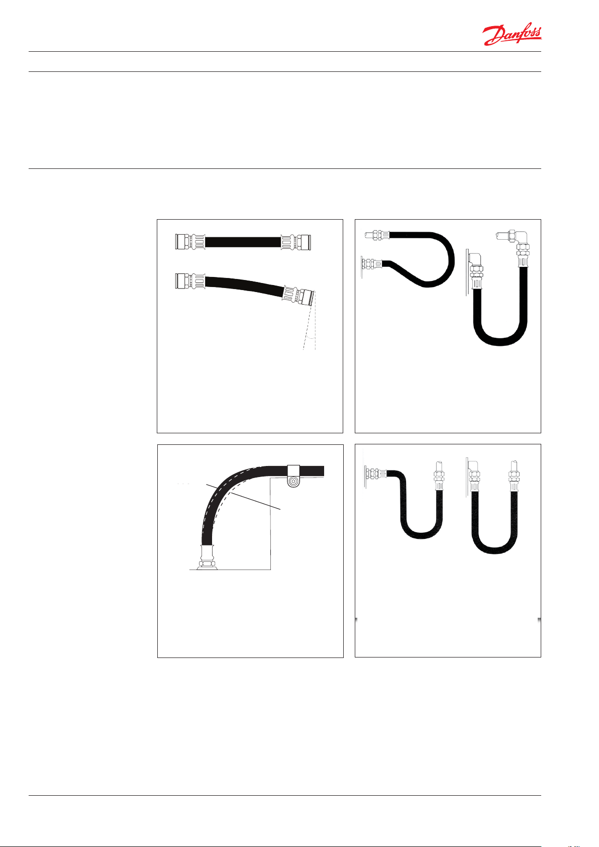
When hose installation is straight, allow enough slack in hose
line to provide for length changes which will occur when pres-
sure is applied.
Prevent twisting and distortion by bending hose in same plane as
the motion of the boss to which hose is connected.
User proper angle adaptors to avoid sharp twist or bend in hose. Adequate hose length is necessary to distribute movement on
flexing applications and to avoid abrasion.
When radius is below the required minimum, use an angle adap-
tor to avoid sharp bends.
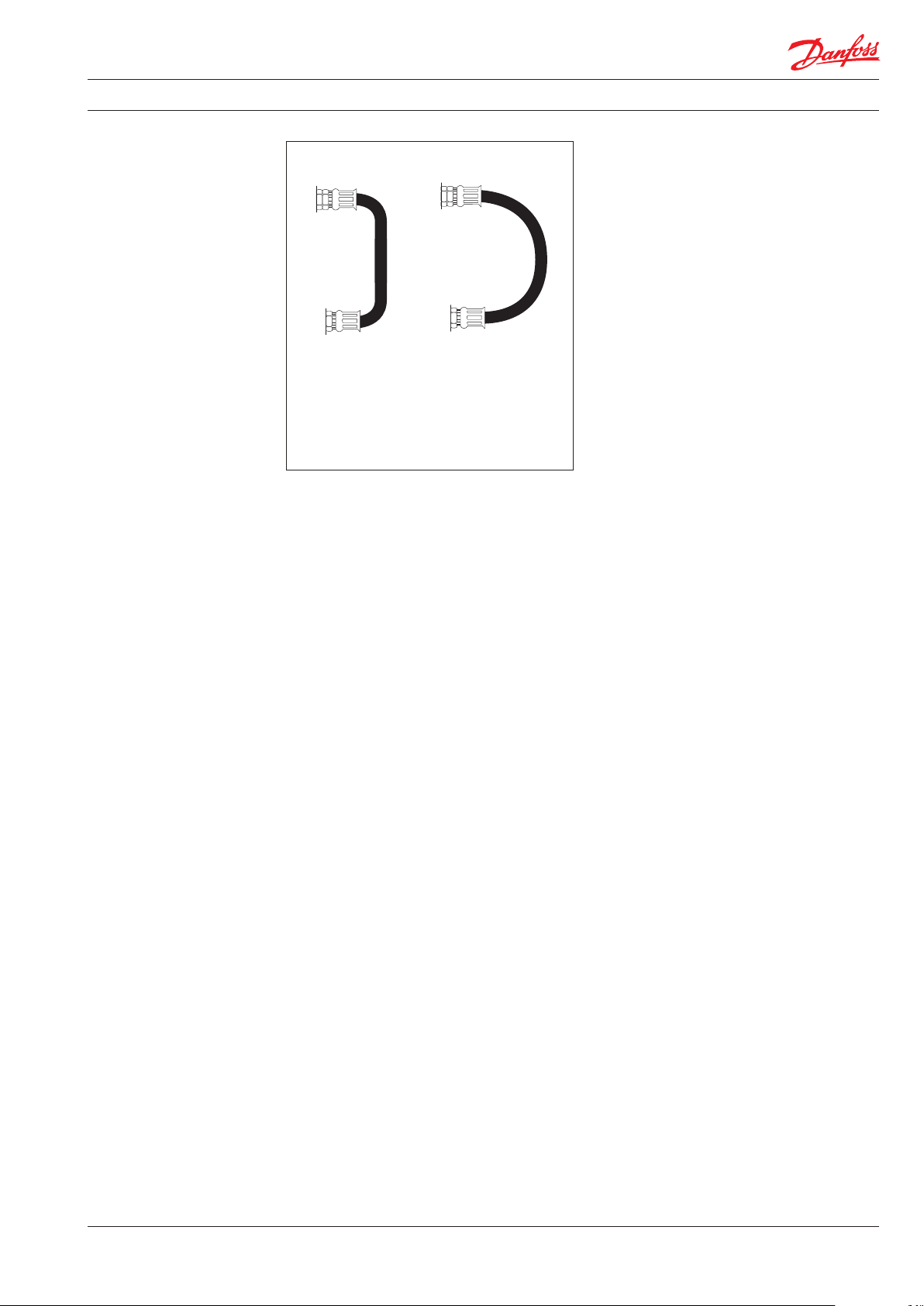
Avoid twisting of hose lines bent in two planes by clamping hose
at change of plane.
Hose assembly routing tips
HOSES & HOSE COUPLINGS
GS-HYDRO PRODUCT CATALOGUE
Assembly and installation
When hose installation is straight, allow enough slack in hose
line to provide for length changes which will occur when pres-
sure is applied.
Prevent twisting and distortion by bending hose in same plane as
the motion of the boss to which hose is connected.
Avoid twisting of hose lines bent in two planes by clamping hose
at change of plane.
Hose assembly routing tips
HIGH
PRESSURE
NO
PRESSURE
Correct hose installation is essential for safe and
satisfactory performance. The size of the hoses
impacts the installation recommendations. This
manual has therefore been split in recommendation for hoses up to 2” and recommendation
larger than 2”.
1. Hoses up to 2” When installing hoses, avoid twisting the hose as
the hose will try to straighten under pressure.
MIN. 10°
Always provide some angle on straight
hose installations, this reduces forces
and ensures that hose is only bending i
one direction. The Hose must have some
slack to compensate for hose length
variations.
Hose routing tips:
Danfoss recommends installing hose whip
restraints whenever your pressurized hose
assemblies are in proximity to personnel or
crucial equipment.
Check with these examples when installing
your hoses.
This can cause hose failure via hose blowout
from the tting and/or hose burst at the point of
strain.
WRONG
RIGHT
When radius is below the required minimum, use an angle adap-
tor to avoid sharp bends.
At radius below required minimum, angle
adapters should be used to prevent sharp
hose bends.
NO
PRESSURE
To allow the hose to expand when
pressurized, clamps should not be used at
bends. If possible, do not clamp high and
low pressure lines together.
HIGH
PRESSURE
WRONG
RIGHT
Use proper angle adapters to avoid sharp twist
or bend of hose.
2
180R9434 | AN375455762639en-00 0201 | 07.2021
Page 3
Instruction | Right and wrong - Hose assembly routing tips
WRONG
WRONG RIGHT
To prevent hose collapse and ow restriction,
hose bend radii should be kept as large as
possible. Tight bends can also compromise
the hose reinforcement and cause premature
hose failure. Refer to hose specication table
on page 6 for minimum bend radii.
RIGHT
180R9434 | AN375455762639en-00 0201 | 07.2021
3
Page 4

Instruction | Right and wrong - Hose assembly routing tips
2. Hoses larger than 2”
Whenever possible, high pressure hoses should
always be connected directly to Danfoss provided adapters and check valves. Elbows and
distance pipes should be avoided to prevent
excessive side loads.
MIN. 10°
Always provide some slack on straight hose installations. This compensates for hose length
variations with dierences in internal uid
pressures. A small angle will reduce the forces
from the hose and allow the hose to bend
when pressurized.
Danfoss 3” HP hoses are nylon reinforced; when
using hoses that are not steel reinforced the
connected items must be grounded to avoid
electrical stray currents.
EXPANSION
EXPANSION
EXPANSION
Flexing a metal hose in two separate planes of
movement will torque the hose assembly.
Always install the metal hose assembly so
that exing occurs in one plan only and this
is the same plane in which bending occurs. If
multiple planes of motion are required use a
dog leg assembly.
The installation should allow a straight
distance S before bending the hose. Not
doing so may compromise the hose
reinforcement and cause hose failure.
Max. bending angle and distance S can be
found in table 1 on page 6.
WRONG
RIGHT
Hoses should not be twisted and should
only have one bend.
4
180R9434 | AN375455762639en-00 0201 | 07.2021
Page 5

Instruction | Right and wrong - Hose assembly routing tips
The use of pipe or ttings between pump
and iSave connectors and hoses should
be avoided. Such congurations can apply
excessive loads on the connectors and can
cause connector and/or connector bolt
failure. If this cannot be avoided, the piping
system must be protected by either hose
whip restraints mounted directly to the
frame or the hard piping must be xed relative to any pump/iSave movements.
MAX.
BENDING
ANGLE
If hose is bent, ensure max. bending angle
and distance S from each connector (see
table 1 on page 6).
WRONG
WRONG RIGHT
To prevent hose collapse and ow restriction,
hose bend radii should be kept as large as
possible. Tight bends can also compromise
the hose reinforcement and cause premature
hose failure. Refer to hose specication table
on page 6 for minimum bend radii.
NO
NO
PRESSURE
PRESSURE
RIGHT
HIGH
HIGH
PRESSURE
PRESSURE
WRONG
RIGHT
The hose must have a distance S before
bending starts.
To allow the hose to expand when
pressurized, clamps should not be used at
bends. If possible, do not clamp high and
low pressure lines together.
180R9434 | AN375455762639en-00 0201 | 07.2021
5
Page 6

Instruction | Right and wrong - Hose assembly routing tips
S
3. Hose specication
table
High pressure hoses
Code
number
180Z0228
Pipe connection1)
[A]
1.5" Vic. OGS Super duplex
Pipe
connection
material
EN 1.4410
Hose size
Inner
diameter
25.4 mm (1.0") 0.66 m (26") 152 mm (6.08"), max. 90° 79 mm (3.11”)
Hose length
ISO 1436
[B]
Bending radius S
180Z0229 1.5" Vic. OGS
180Z0167
180Z0140
180Z0263 2.5" Vic. OGS
180Z0280
180Z0619
180Z0618
180Z0 612
18 0Z0 611
180Z1000
180Z1001
Low pressure hoses
180Z0298 2.0” Vic. OGS
180Z0144 3.0” Vic. OGS
1.5" Vic. OGS Super duplex
2.0" Vic. OGS Super duplex
2.5" Vic. OGS Super duplex
2.5" Vic. OGS Super duplex
2.5" Vic. OGS Super duplex
3.0" Vic. OGS Super duplex
3.0" Vic. OGS Super duplex
3.0" Vic. OGS Super duplex
3.0" Vic. OGS Super duplex
Super duplex
EN 1.4410
EN 1.4410
EN 1.4410
)
Super duplex
EN 1.4410
EN 1.4410
EN 1.4410
EN 1.4410
EN 1.4410
EN 1.4410
EN 1.4410
EN 1.4410
Super duplex
EN 1.4410
Super duplex
EN 1.4410
25.4 mm (1.0")
38.0 mm (1.5") 1.16 m (45.7") 250 mm (9.84"), max. 180° 85 mm (3.35”)
50 mm (2.0") 1.25 m (49") 630 mm (24.8"), max. 90° 115 mm (4.53”)
50 mm (2.0") 1.78 m (70") 630 mm (24.8"), max. 180° 115 mm (4.53”)
50 mm (2.0") 1.00 m (39.4") 630 mm (24.8"), max. 90° 115 mm (4.53”)
65 mm (2.5") 1.78 m (70") 200 mm (7.87"), max. 270° 150 mm (5.90”)
65 mm (2.5")
76 mm (3.0") 1.79 m (70.5") 250 mm (9.84"), max. 270° 150 mm (5.90”)
76 mm (3.0") 1.00 m (39.4") 250 mm (9.84"), max. 90° 150 mm (5.90”)
76 mm (3.0") 1,25 m (49") 250 mm (9.84"), max. 180° 150 mm (5.90”)
76 mm (3.0") 1,6 m (63") 250 mm (9.84"), max. 180° 150 mm (5.90”)
1.16 m (45.7")
1.00 m
(9.4")
2.0 m
(79”)
2.0 m
(79”)
152 mm (6.08"), max. 180° 79 mm (3.11”)
200 mm (7.87"), max. 90° 150 mm (5.90”)
1)
The installation instuction for Style 77DX is located in the Victaulic document I-100 Field Installation Handbook (htpp://static.victaulic.com)
O. D.
r
α
S
6
180R9434 | AN375455762639en-00 0201 | 07.2021
When using exible hoses, it is
recommened to use Hose Whip Restraint.
Page 7

Instruction | Right and wrong - Hose assembly routing tips
180R9434 | AN375455762639en-00 0201 | 07.2021
7
Page 8
Danfoss A/S
High Pressure Pumps • danfoss.com • +45 7488 2222 • E-mail: highpressurepumps@danfoss.com
Any information, including, but not limited to information on selection of product, its application or use, product design, weight, dimensions, capacity or any other technical data in
product manuals, catalogues descriptions, advertisements, etc. and whether made available in writing, orally, electronically, online or via download, shall be considered informative, and
is only binding if and to the extent, explicit reference is made in a quotation or order conrmation. Danfoss cannot accept any responsibility for possible errors in catalogues, brochures,
videos and other material. Danfoss reserves the right to alter its products without notice. This also applies to products ordered but not delivered provided that such alterations can be
made without changes to form, t or function of the product. All trademarks in this material are property of Danfoss A/S or Danfoss group companies. Danfoss and the Danfoss logo are
tradem arks of Danfo ss A/S. All righ ts reserved .
© Danfoss | DCS (im) | 2021.07
180R9434 | AN375455762639en-000201 | 8
 Loading...