

Technical Article - hydronic balancing
New ways of balancing
two-pipe systems
How to achieve superior hydronic balance in heating
systems by utilising the Danfoss Dynamic Valve™
type RA-DV and the Grundfos MAGNA3 speed
controlled pump
dynamic.danfoss.com
Introduction
The challenge: balancing two-pipe systems
Low energy consumption in buildings is not something which
comes easy. Ensuring that the components in a heating system
work together is a pre-requisite when we want low heating bills.
A means of ensuring low energy consumption is to balance the
heating system correctly, and this article will explain how the
new Danfoss Dynamic Valve™ type RA-DV and the new Grundfos
MAGNA3 speed controlled pump work together superbly to
achieve this.
We will first look at how we
compensate for the variations in
partial, and how the requirement to
balance the heating system means we
need to control flow; and to obtain
this, we need to control the differential
pressure across valves as well.
We will show how this can be done
by utilising the Danfoss Dynamic
Valve™ type RA-DV in combination
with the Grundfos MAGNA3 variable
speed controlled pump, looking at
an installation in Fredericia, Denmark,
where 60 apartments in a 10 storey
building has heating supplied from
a system consisting of two Grundfos
MAGNA3 pumps serving two mixing
loops, each supplying 10 raisers, each
of which has manual balancing valves
of Danfoss type MSV mounted. This
installation showed that utilising the
speed controlled Grundfos MAGNA3
pump and Danfoss Dynamic Valve™
type RA-DV in combination ensures
problem free operation of a heating
system.
The difference today is that designated
flow can now easily be set on each
radiator and pump set point by
means of the new Danfoss dP tool™
(for measuring differential pressure)
in combination with Grundfos GO
(offering mobile access to Grundfos
online tools). Not only does this
ensure pump optimisation and lowest
energy use, it also reduces time for
commissioning substantially.
The uneven distribution of heat
between units – single radiators or
apartments – in a heating system
is what we refer to as a balancing
problem. A heating system is balanced
when an even distribution of hot water
is ensured thereby ensuring maximum
comfort at minimum running cost.
LOAD
100%
75%
50%
25%
428 1050 2450 3080
6% 15% 35% 44%
In order to compensate for the
variations in load, we equip our
systems with thermostatic valves on
each radiator. The thermostat will
reduce the flow through the individual
radiator and ensure the required room
temperature is maintained.
Or to put it in another way, a heating
system is in balance when the flow
in the whole system corresponds to
the flow rates that were specified for
the design of the system. This is a key
challenge for many two-pipe systems.
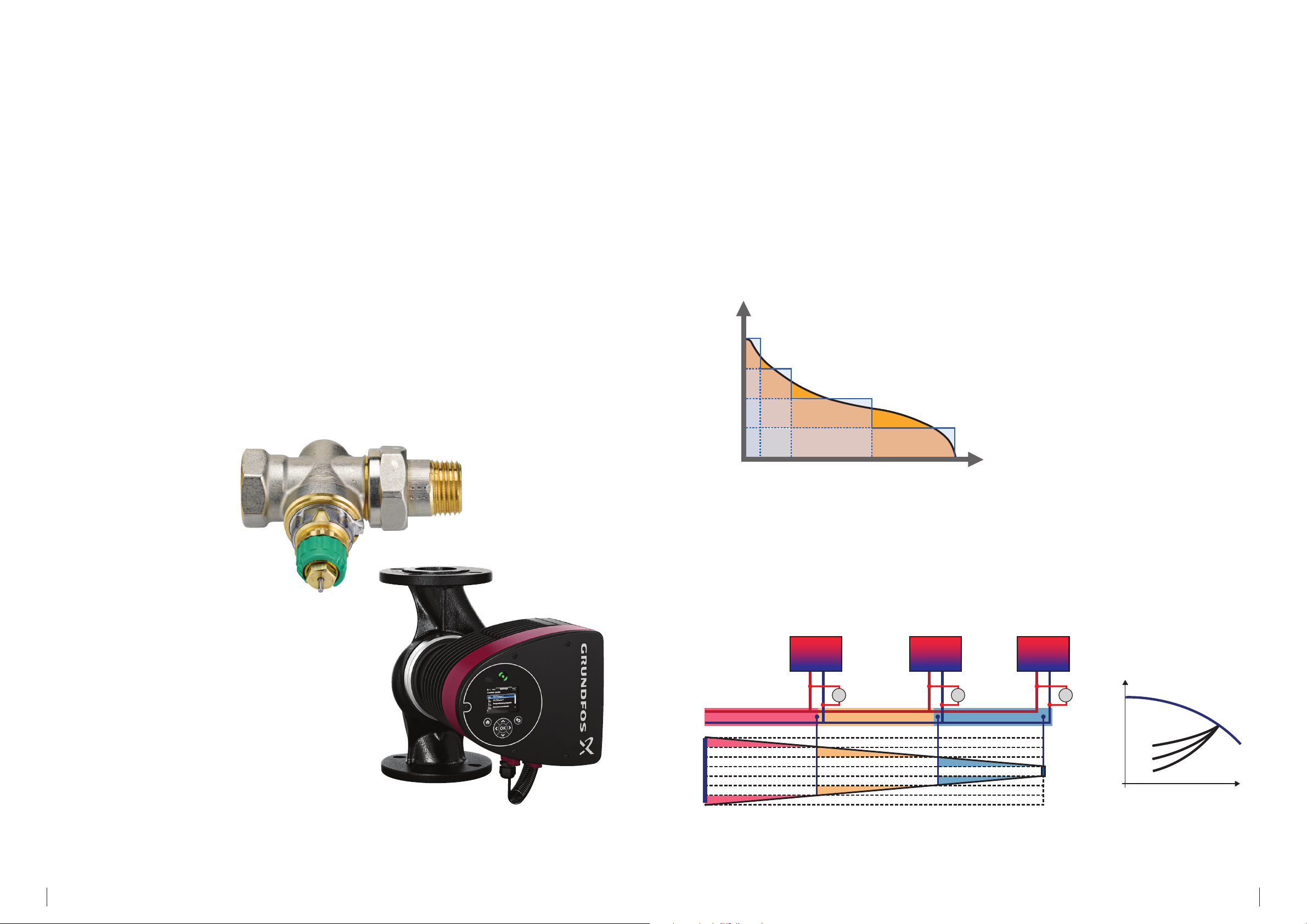
Let us first look at the general
challenge in operating two-pipe
heating systems. The load profile below
shows how load is changing during a
heating season in Europe. In only 420
hours out of 7000 heating hours do we
need 100% capacity from our heating
system.
HOURS
As pressure loss increases by the
square of flow, the differential pressure
across the first radiator valves is
substantially higher than it is at the last
consumer, as shown in the illustration
below.
Heating systems need to be
commissioned properly to ensure
high comfort and lowest possible
cost of operation. In earlier days
commissioning was a complicated
matter where lots of different valves
and measuring tools needed to be
utilised for proper commissioning.
RAD RAD RAD
1 32
∆p
a.
∆p
b.
∆p
H
c.
a.
b.
c.
Q
32

As different radiators need different flows in order to heat up the room in question, it is possible to pre-set the maximum
flow on each radiator valve. The pre-setting can be seen in the graph below for a typical radiator valve. The pre-setting can be
adjusted from 1-7 and finally in “N position” which indicates a fully-open valve.
Static vs dynamic commissioning
of heating 2-pipe systems
When a heating system is equipped with a constant speed pump, the delivered differential pressure will vary greatly, as shown
in the illustration below. When flow is reduced the delta P across the individual valve will increase. In the above example the
needed flow at max load is 37 l/h. But when the differential pressure increases (+0.2 bar), the flow will increase, as shown to 62
l/h = 67 %.
A major challenge is that heating
systems are often constructed
and designed to meet the heating
requirements in the worst case
scenario, such as when outdoor
temperatures are extremely low. But as
this occurs only a few times every year
(if at all) the system will be oversized
in the remaining period. This typically
results in overspending on energy.
The following example of static
commissioning of a heating system
with dynamic requirements is from
an installation in Fredericia, Denmark,
where 60 apartments in a 10 storey
building has heating supplied from
a system consisting of two Grundfos
MAGNA3 variable speed controlled
pumps serving two mixing loops,
each supplying 10 raisers, with a total
273 RA-N DN 10 radiator valves and
and static balancing valves of Danfoss
type MSV mounted. The building is
from 1972 and was renovated in 1985,
including new windows and façade.
2
Delta P increase from
0,1 bar to 0,3 bar
1
FLOW
100% load 420 hours
As flow decreases, the differential pressure increases in a fixed speed pump.
The conclusion is that, in order to meet the designated flow, we need to control the differential pressure across valves as well.
We will now see how this was done.
100%
The two mixing loops each supply
10 raisers at the 10 storey apartment
building in Fredericia, Denmark.
54

We will now look at how the system
COOPERATION PUMP AND VALVES
20% 40% 50% 70% 100%
0 2 4 6 8 10 12 14 16 18 20 22 Q [m³/h]
0
1
2
3
4
5
6
7
[m]
H
MAX
MIN
operates, with static balancing
valves and static radiator valves, with
pre-setting. Later, the same test is
performed, but this time with dynamic
valves. The test is done not only at full
load but more importantly at partial
load too.
At the same time, differential
pressure has been measured at the
furthest radiator to make sure that
there is enough pressure to reach
the designated flow for the radiator
furthest away, in this case it is 10 kPa
and the designated flow is 30 l/h,
so the pre-setting will be 2.5 for the
radiator valve.
In the test we have set the control
mode for the pump to be proportional
pressure mode first and secondly
constant pressure mode.
And then we have added the new
Danfoss Dynamic Valve™ type RA-DV in
combination with the new Grundfos
MAGNA3 speed controlled pump.
The MAGNA3 pump can be set in
proportional pressure mode, which will
enable the pump to reduce delivered
differential pressure, when flow is
decreasing. See the chart, below left.
PRESSURE
PUMP CURVES
DESIGN
100%
85%
75%
70%
+4,4
60%
+4,0
+3,0
+3,1
DUTY POINT
CONTROL CURVE
RADIATOR VALVE
SYSTEM CURVE
ADITIONAL DELTA P
FLOWLIMIT AREA
FLOW
The red line shows the proportional control
curve and the green line the minimum required
differential pressure in the system. As can be
seen from the blue circles, there will always be
surplus differential pressure available. Therefore
we need the pump and the dynamic radiator
valve to work well together.
So what that this tell us is that, with
static radiator valves at partial load of
50 %, the radiators will have (17.1- 7.8)
+
= 9.3 kPa increased pressure. What this
means in risk of overflow can be seen
in the figure below.
H
p
[m]
[kPa]
7
60
50
40
30
20
10
MAX
6
5
4
3
2
1
0
0
0 2 4 6 8 10 12 14 16 18 20 22 Q [m³/h]
MIN
Even though the MAGNA3 pump
reduces its delivered differential
pressure, there will at partial load still
be a delta P surplus across the radiator
valves*, shown in the table below.
H
[m]
7
MAX
6
5
4
3
2
1
0
0 2 4 6 8 10 12 14 16 18 20 22 Q [m³/h]
MIN
The key issue here is that although
a speed controlled pump helps, it
cannot keep differential pressure
stable; this is an issue solved by
pressure-independent dynamic valves.
Static radiator valve
Control mode,
pump
Proportional 10.2 kPa 18.0 kP a 7.8 k Pa 33 % increase
Constant 10.2 kPa 27. 3 k Pa 17.1 kP a 46 % increase
System load
100 %
System load
50 %
Increased ΔP
(by 50 % load)
Increased flow
Meassured values at the radiator furthest away
Dynamic radiator valve
Control mode,
pump
Proportional 9.8 kPa 10. 5 kPa 0.7 k Pa < 1 % increase
Constant 9.9 kPa 10. 6 kPa 0.7 kPa < 1 % increase
System load
100 %
System load
50 %
Increased ΔP
(by 50 % load)
Increased flow
Meassured values at the radiator furthest away
When differential pressure increases
from 7.8 kPa to 17.1 kPa, the flow will
increase from 80 to 132 l/h, whereas
the dynamic valve will keep the flow
constant.
The increased delta P at part load
would create overflow and increase
the heating bill, showing the need to
control the delta P correctly. Using the
Using the Danfoss dP tool™ to balance a radiator.
Danfoss Dynamic Valve™ type RA-DV
keeps the flow constant, even when
delta P is changing. A differential
pressure controller inside RA-DV keeps
the pressure drop over the control
valve on the constant level which
means that a constant flow through
the RA-DV valve is maintained. This is
shown in the graph below.
*Assuming that the heating system is a traditional widespread system. If this is not the case
and instead the system is equally divided in two parallel systems, the optimum control
mode will be constant pressure.
So the answer to the challenge
about additional delta P, is to utilise
a speed controlled pump like the
Grundfos MAGNA3 and use Danfoss
Dynamic Valve™ type RA-DV, which
in combination ensures problem free
operation of a heating system, and this
has been shown from the example
from Fredericia discussed above. The
installation has been running now for
one year, and we can see that the cost
for pump operation has been reduced
by approximately 57 % or equal to 980
kWh/year.
76

Danfoss A/S · Heating Segment · Ulvehavevej 61 · 7100 Vejle · Denmark
Te
Pump optimisation
If the pump runs optimally, the lowest
possible energy use is ensured.
Pump optimisation together with
proportional pressure control is
possible only with automatic balancing
valves. Commissioning is made easy
using the new Danfoss dP tool™
(for measuring differential pressure)
in combination with Grundfos GO
(offering mobile access to Grundfos
online tools), and ensures pump
optimisation and lowest energy use.
The Danfoss dP tool™ is an extremely
useful, simple and unique tool used
during commissioning that measures
Conclusion
Superior heating systems need thorough
commissioning, when lowest possible
energy bills is the goal. By using the
new and innovative Danfoss Dynamic
Valve™ type RA-DV in combination
with the new Grundfos MAGNA3
variable speed controlled pump,
this is now highly achievable. In the
specific case in Fredericia, Denmark,
the achieved savings adds up to not
less than 12 % of the heating bill. This
is only possible utilising both the new
Danfoss dynamic valve in combination
with the new Grundfos MAGNA3 pump.
the available differential pressure. It is
mounted on the critical valve where
the differential pressure is lowest. In
full load mode, the delta P needs to be
10 kPa. If the differentail pressure turns
out to be either lower or higher than
this, the set point, is adjusted on the
MAGNA3 pump. The setpoint is related
to the differential pressure delivered
by the pump. Note that this value will
always be higher than what messured
across tha critical valve, as differentaial
pressure decreases throughout the
system.
Grundfos GO is the mobile tool box
The difference today is that designated
flow can now easily be set on each
radiator and pump set point can be
set by using both the Danfoss dP tool™
and Grundfos GO. Not only does this
secure optimal function, it also reduces
time for commissioning substantially.
This shows that there are plenty
of reasons for you as a consulting
engineer to chase down the potential
energy savings that are out there in
many housing associations.
for professional users on the go. It is
the most comprehensive platform
for mobile pump control and pump
selection including sizing, replacement
and documentation and can be downloaded to any iOs or Android device.
Having completed these steps you
have ensured that the energy system
is correctly commissioned, not only
at design flow conditions, but also
and most importantly at partial load
conditions. Result will be lowest
possible energy consumption for the
entire heating system.
Heating systems need proper
commissioning to ensure high
comfort and the lowest possible
cost of operation. In earlier days
commissioning was a complicated
matter where lots of different valves
and measuring tools were needed for
proper commissioning.
l.: +45 7488 8500 · Email: heating@danfoss.com · www.heating.danfoss.com
VFGWK202
Rene Hansen, Anders Nielsen,
Danfoss Grundfos
June 2015
Grundfos GO, for
Android and iOS.
© Copyright Danfoss | ... | 2019.06
 Loading...