

Page 1

Document category | Product name
Application manual | Ground application. Ice & Snow Melting
Ground application.
Ice & Snow Melting
Application manual
Page 2

Page 3

Let Danfoss do the work
Index
Danfoss Group is Denmark's largest industrial group. It is one of the world's
leading companies within heating, cooling and air-conditioning. The Danfoss
Group has more than 23000 employees and serves customers in more than 100
countries.
Danfoss is Europe’s leading brand of electrical cable heating systems and electric
pipe heating systems with over 70 years of experience. The production of
heating cables takes place in France and Poland while the head office is situated
in Denmark.
The value of experience
We have installed literally thousands of systems across the globe, in every
conceivable setting. This experience means that we can offer you practical
advice about precisely which components you need to get the best results at
the lowest cost.
Ground application. Ice & Snow Melting
This design guide presents Danfoss’s recommendations for design and
installation of ice and snow melting systems for ground application.
It provides guidance for heating cable positioning, electrical data and system
configurations.
Following Danfoss’s recommendations will ensure energy efficient, reliable and
maintenance free solution for constant wattage heating cables with 20 year
warranty.
1. Application Briefing 4
2. System Description 5
3. Products 6
4. System Design 10
5. Installation 15
6. Appendixes 19
7. Cases 24
Our quality management
system
and compliances
ISO 9001 TS 16949
ISO 14001
Along with full compliance with EU
directives and product approvals
Page 4
1. Application Briefing
Winter weather costs
In recent years there have been
plenty of new stories about human
and financial costs caused by harsh
winter weather. Property damage,
increased maintenance expenses,
lost productivity, rising insurance
premiums, personal injuries and even
worse. Installation of Danfoss Ice &
Snow Melting System ensures a steady
solution to address cold weather
related problems.
Danfoss’s ice and snow melting system
is designed to provide safety for
people, vehicles, and buildings safety
through safe walking and driving
during winter and safety in terms of
less damage to buildings.
Ground solutions –
with a first class product range
By using Danfoss heating cables
and mats controlled by electronic
thermostats with moisture sensors,
you can cost-effectively protect large
areas such as parking areas, ramps
or pedestrian accesses to buildings
giving you convenience and safety
while saving a lot of tiring and timeconsuming manual work.
Benefits
• Efficient snow removal - area is kept free from ice
and snow at all times
• No manual snow removal and salting becomes
unnecessary.
• Safe traffic and working areas for people
• Flexible system for most common surface covering
materials
• Cost saving for outdoor surface repair after winter
• Environment is protected against salting and
antifreeze related damages.
• Automatic ”Around the Clock” snow clearing service.
• Smart 2-zone control with low energy consumption
• Prioritizing – limited power output solution
• A maintenance free system with 20 year full
warranty on cables
One of the greatest advantages of
these systems is the most energy
efficient solution for the ground ice
and snow melting applications.
4
Application manual · Ground application. Ice & Snow Melting · VGHWD102 · ©Danfoss
Page 5
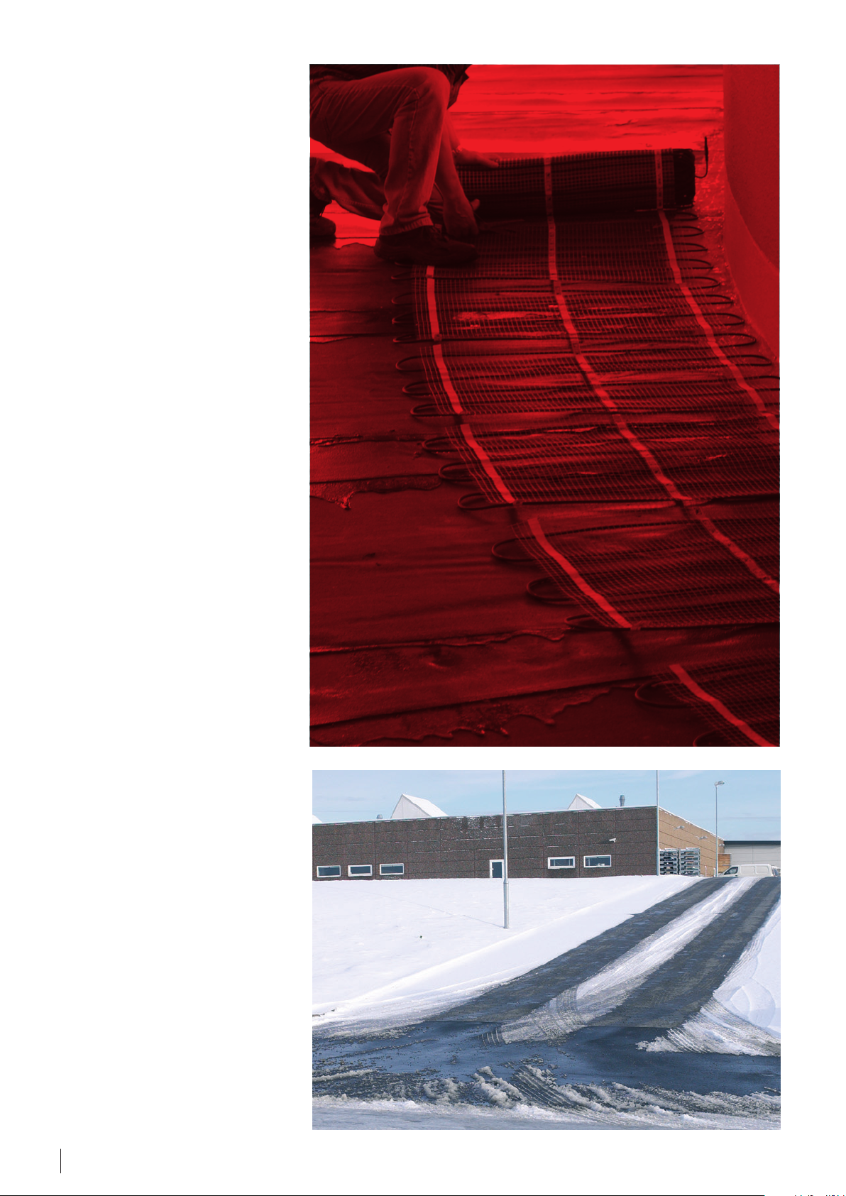
2. System Description
Main purpose of the system is to melt
and remove snow and ice from ground
surfaces.
The most common Danfoss ice and
snow melting ground applications
are in residential car parking areas,
driveways, pavements, outdoor steps,
loading platforms, ramps, bridges and
drainage areas. It is even possible to
melt snow and ice on mastic asphalt
surfaces by using special heating
cables.
When heating cables are installed
to melt snow or slippery ice on the
ground, safety and cost saving go hand
in hand.
It can be done manually or in a smart
way – by means of electrical Ice &
Snow Melting system with thermostat
control and moisture and temperature
sensors that can control 2 zones
simultaneously. Inactive during cold
but dry weather 2 zone control saves
energy and reduces costs.
The automatic regulation of the snow
melting system keeps areas free from
snow and passable at all times – night
and day.
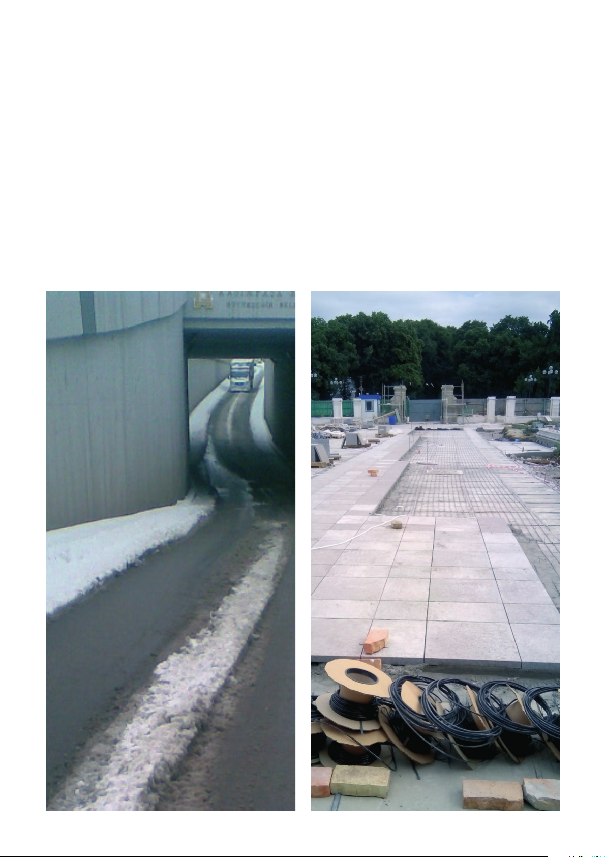
When installing ice and snow melting
systems on steep slopes it may be
necessary to provide some drainage for
melted water at the slope bottom. The
drain system should also be protected
against ice formations.
Application manual · Ground application. Ice & Snow Melting · VGHWD102 · ©Danfoss
5
Page 6
3. Products
Electrical heating system consists of
two major components:
• Heating element – heating cable or
heating mat;
• Thermostat with a temperature
sensor or regulator/controller with
temperature and moisture sensor(s).
Heating cables and mats for Ground
applications are usually installed into
concrete construction or into special
glue under tiles.
Danfoss heating cables and mats for
Ground applications are designed for
installation in concrete constructions
or into special glue under tiles. Usual
thickness of top/finish concrete layer
for outdoor applications is at least 5
cm. But the thickness should comply
with a ground construction and local
norms and regulations.
Heating cables used in ground
constructions are serial resistive cables,
single or twin conductor. Most of
cables and mats are manufactured as
ready-to-install heating elements wth
a specific length (i.e. 7, 10, 15, up to
229 m), with connecting power supply
cable (cold lead or cold tail) and sealed
joints (muffs or end terminals).
Heating elements
For Ground Ice and Snow Melting
systems the following resistive
(constant wattage) heating elements
can be used.
Heating cables:
• Twin conductor ECflex 18T and
ECflex 20T (230 V);
• Single conductor ECbasic 20S
(230 V);
• Twin conductor ECsafe 20T (230 V);
• Twin conductor ECsnow 20T and
ECsnow 30T (230/400 V);
Note. The number at the end of the
cable’s and mat’s name refers to its
linear output – W/m or area output –
W/m², at 230 V or 400 V.
Letter “T” means twin conductor
cable/mat (Twin), letter ”S” – singleconductor cable/mat (Single).
Danfoss resistive heating cables ensure
safe, efficient and economical ground
application.
To ensure long life-time and quality
all cables are thoroughly inspected
including tests for ohmic resistance,
high voltage and material control.
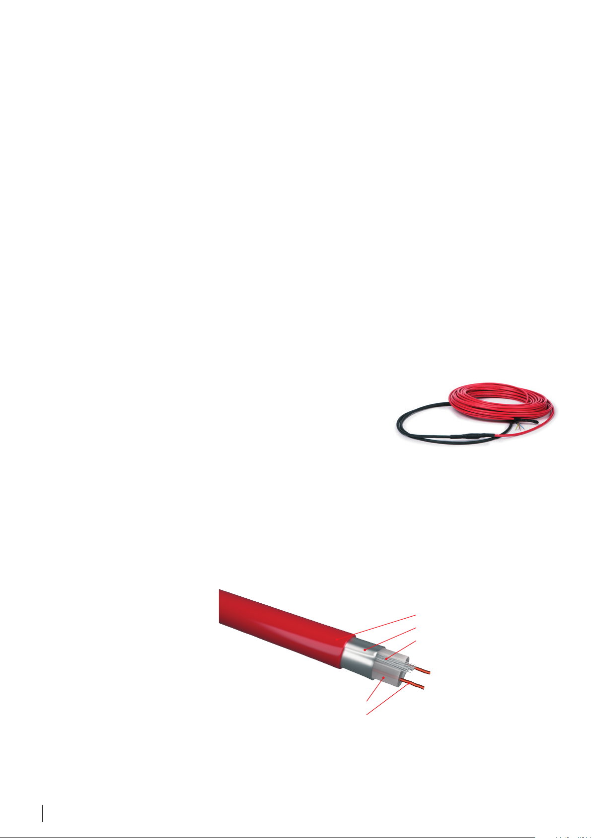
ECflex. It is a twin conductor fully
screened heating cable for installation
in concrete, pipe heating etc. The cable
complies with IEC 60800:2009 class M2,
and is designed for applications with
the high risk of mechanical damage.
It is supplied in readymade sets with
2,3 m cold lead, sealed joints and end
muffs.
Cable diameter is Ø 6,9 mm.
The cable is available for 230 V power
supply.
Cables of 18 and 20 W/m (230 V) linear
output are available.
Cable length:
ECflex 18T: 7,3-150 m ;
ECflex 20T: 7,1-148 m.
ECflex
Range of heating cables linear output
for ground application is usually
15-30 W/m. Danfoss ready-made
cables are available with 18, 20,
30 W/m output (for 230 and 400 V).
Most Danfoss cables are manufactured
and approved in accordance with the
latest revision of IEC 60800:2009, with
M2 mechanical strength class (for
rough concrete constructions).
The main type of Danfoss heating
cables is twin conductor heating
cables. Internal design of a modern
twin conductor ECflex cable are shown
in the figure below.
The most used heating elements for
Ground Ice and Snow Melting systems
are ECbasic, ECflex and ECsafe heating
cables.
Internal insulation ( XLPE)
Heating element (resistance thread)
ECflex heating cable construction
ECbasic. It’s a single conductor
screened heating cable complied with
IEC 60800:1992 class C and intended
for installation in concrete, for pipe
heating etc. It’s supplied in readymade
sets with 2 x 3 m cold leads and
2 sealed connection muffs.
Outer coating made of PVC
Protective screen foil (Aluminum)
Protective conductor
6
Application manual · Ground application. Ice & Snow Melting · VGHWD102 · ©Danfoss
Page 7
Cable diameter is Ø 5,5 mm.
ECbasic 20S is available with
20 W/m output for 230 V power supply.
Cable length:
ECbasic 20S, 230 V: 9-228 m.
ECbasic 20S readymade
ECsafe. It is a twin conductor fully
screened heating cable for installation
on roofs, in gutters, down drain pipes
and on the ground.
The cable has UV stable tough outer
sheath which complies with IEC
60800:2009 class M2, and is designed
for applications with the high risk of
mechanical damage. It is supplied in
readymade sets with 2,5 m cold lead,
sealed joints and end muffs.
The cable is available with linear
output of 20 W/m and 30 W/m in two
options for 230 V and 400 V power
supply.
Cable length:
ECsnow 20T, 230 V: 12-205 m;
ECsnow 30T, 230 V: 8,5-215 m.
Fixing
In case of heating cables application,it
is recommended to use fittingbands
to fix the cable to the base, e.g. ECfast
metal galvanized fitting band (see
Appendix A.2 ). It should be attached
to the ground (e.g. nailed down) in
parallel lines usually at intervals of
50 cm or using 2 meters of fitting
band per each square meter of cable
installation. The same applies to plastic
bands.
ECfast
As an alternative to control small areas
near private houses etc. EFET 130 wall
mounted room thermostat can be used.
All thermostats above are supplied
with a wire temperature sensor –
NTC 15 kOhm @25 °C, 3 m.
To control ice and snow melting
systems especially with high output
the best solution is EFIT 850 regulator/
controller with integrated ground and
roof moisture and temperature sensors.
EFIT 850 is a two-zone controller with
possibility of connection up to 4
sensors to provide maximum control
of the outdoor heating system.
Comparing to installations with typical
ground temperature measuring this
regulator ensures reducing energy
consumption costs by up to 40%.
Cable diameter is Ø 7 mm.
The cable is available with linear
output of 20 W/m for 230 V power
supply.
Cable length:
ECsafe 20T, 230 V: 6-194 m.
ECsnow. It is a twin conductor fully
screened heating cable for installation
mainly on roofs, in gutters, down drain
pipes. It can be an option for installation
on the ground too. The cable has UV
stable tough outer sheath, FEP conductor insulation, it complies with IEC
60800:2009 class M2 and is designed
for applications with the high risk of
mechanical damage. It is supplied in
readymade sets with 2,5 m cold lead,
sealed joints and end muffs.
Cable diameter is Ø 7 mm.
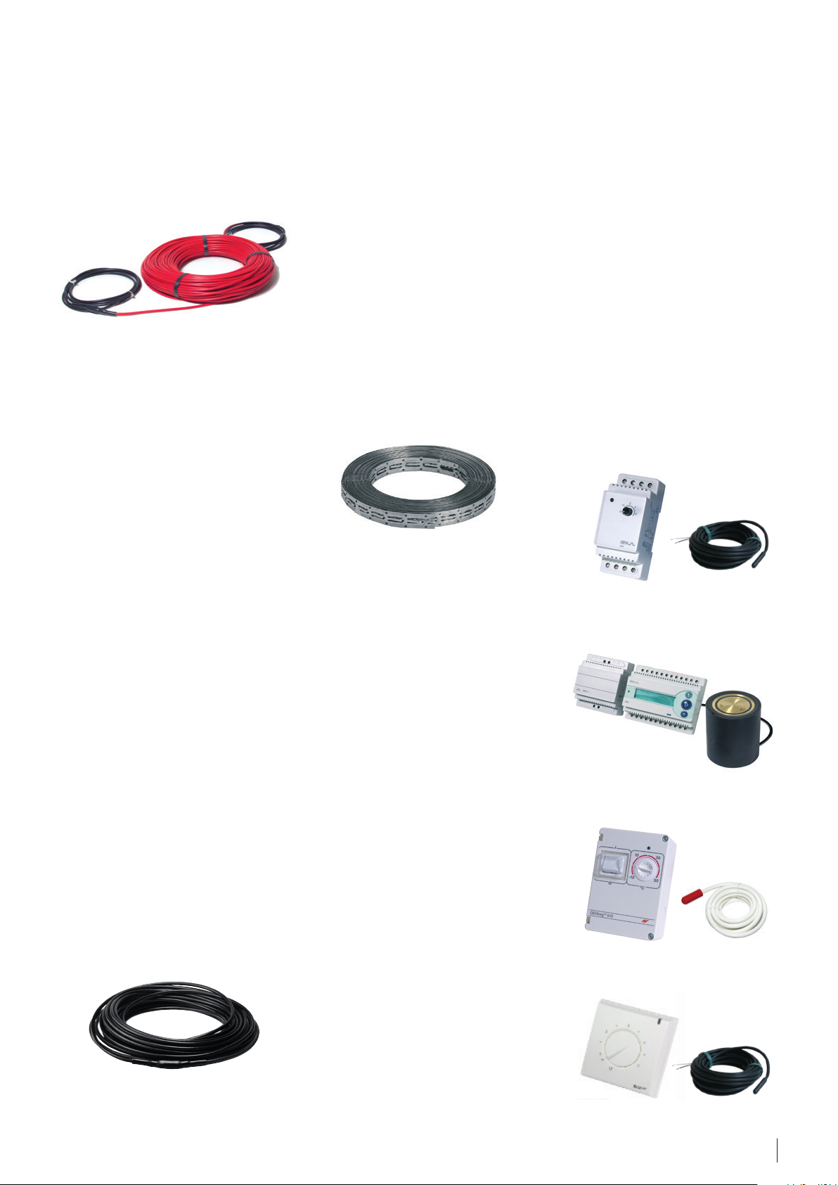
Control
Ice and snow melting systems
are different and require different
thermostats/regulators.
EFET/EFIT thermostats and regulators
are fitted with a complete set of
control functions for heating systems
for ice and snow melting of any type
and allow attaching external sensors
for measuring ground temperature as
well as control of moisture conditions.
The product range of controls is
designed for ground outdoor systems
including the following:
• thermostats with a temperature
sensor – EFET 330 (5…45 °C),
EFET 610;
• regulator with an integrated
temperature and moisture sensor(s)
– EFIT 850.
EFET 330 (5…45 °C)
with wire sensor in set
EFIT 850
with ground sensor
EFET 610
ECsnow
To control simple or low output
systems a thermostat with a ground
temperature sensor is recommended.
EFET 330 (5…45 °C) thermostat
with the DIN rail attachment is
recommended as a standard solution.
Also can be used EFET 610, IP44 with
on wall/pipe mounting.
Application manual · Ground application. Ice & Snow Melting · VGHWD102 · ©Danfoss
EFET 130
7
Page 8
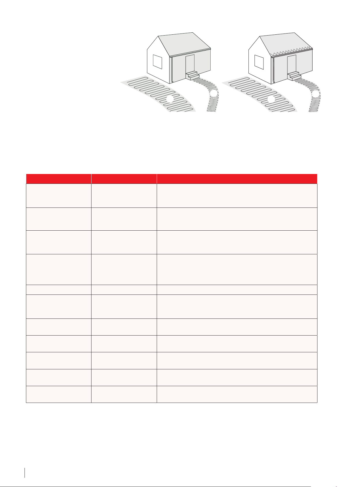
Zone support saves energy
The EFIT 850 lets you divide your area
in to 2 zones, e.g. a North and South
side. In this way it is possible to save
energy, when the South side is free
of ice and snow faster because of the
heat from
the sun.
Prioritizing – for limited power
output
You can prioritize between the zones,
e.g. if you have limited power output.
This way one zone is made ice and
snow free before focus is put on the
other zone.
Products – general overview for Ground ice and snow melting systems
Product Options Description
Resistive heating cable
ECflex
Resistive heating cable
ECbasic 20S
ECflex 18T, 230 V;
ECflex 20T, 230 V
ECbasic20S,
230 V
A
B
Twin conductor, 100% screen, red.
18, 20 W/m (230 V).
DIN IEC 60800:2009 M2
Single conductor, wire screen, red.
20 W/m (230 V).
DIN IEC 60800:1992 C
A
B
B
Resistive heating cable
ECsafe 20T
Resistive heating cable
ECsnow
Fixing ECfast Metal 25 m pack; galvanized metal, fixings every 2,5 cm.
Regulator
EFIT
Moisture & temperature
sensor
Accessories
Thermostat
EFET
Thermostat
EFET
Thermostat
EFET
ECsafe 20T,
230 V
ECsnow 20T,
230 & 400 V program;
ECsnow 30T,
230 & 400 V program
EFIT 850
Ground sensor
for EFIT 850
PSU 24 V
for EFIT 850
EFET 330 (5…45 °C)
EFET 610
EFET 130
Twin conductor, 100% screen, UV stable, black.
20 W/m (230 V).
DIN IEC 60800:2009 M2
Twin conductor, 100% screen, FEP conductor insulation, UV stable,
black.
20 and 30 W/m (230/400 V).
DIN IEC 60800:2009 M2
Connection to Ground and Roof moisture and temp. sensor, max 4
sensors, 2 zones,
2x15 A, PSU 24 V, DIN rail
Ø93 x 98 mm, IP67, 15 m connection cable 4x1 mm²
Extra PSU for EFIT 850 with 3-4 sensors
5…45 °C, 16 A, IP20, with 3 m wire sensor,
DIN rail
-30…+50 °C, 10 A, IP44, with 3 m wire sensor,
on wall/pipe installation
5…45 °C, 16 A, IP30, with 3 m wire sensor,
room on wall installation
For additional information please refer to the Danfoss Catalogue.
8
Application manual · Ground application. Ice & Snow Melting · VGHWD102 · ©Danfoss
Page 9

4. System Design
The following paragraphs contain
estimations according to ASHRAE,
Application Handbook and Historical
Weather Data.
Figures are for reference only and can
vary depending on the area size, wind
speed and ground construction.
4.1 Output
The heat required for snow melting
depends on the following main factors:
• Weather conditions (min.
temperature, max. snowfall rate, wind
speed, humidity, altitude);
• Project details (materials, foundation
type, dimensions, insulation);
• Electrical data (voltage, power, control
requirements);
• System performance expectations;
• Safety factor.
Evaluation of the specific output for
ice and snow melting systems can be
done based on the diagram and other
similar documents.
For more information about
performance of different ice and snow
melting systems, as well as control, see
Outdoor Application manuals.
No back loss & area width 6 m & 50% cloud cover
Surface temp. - 3 °C & 70% relative humidity
700
600
500
400
Heatloss [W/m²]
300
200
100
0
-3 -1 1 3 5 7 9 11 13 15 17 19 21 23 25
Temperature difference [K] between surface and ambience
Fig. 3. Wind and temperature dependent heat loss
When installing ice and snow melting
systems it may be necessary to
provide drainage for melted water at
the slope bottom, walkways, etc. The
drain system should also be protected
against ice formations.
0 m/s
2 m/s
4 m/s
6 m/s
8 m/s
10 m/s
15 m/s
20 m/s
25 m/s
30 m/s
For example, heat loss depending
on the wind speed and temperature
differences between the surface and the
ambient air is described in 2003 ASHRAE
Application Handbook (see fig. 3).
For example, for medium weather
conditions and 6 m/s wind speed, if
choosing ΔT = 10 K (from -3 K to +7 K)
the heat loss value is approx. 230 W/m²
(marked with the red dotted line in fig. 3).
In other words, surface heating up to
10 degrees requires 230 W/m² or
230 / 10 = 23 W/(m²·K).
All in all, for medium winter weather
conditions, heating of 1 m² outdoor
surface up to 1°С needs power of
approx. 23 Watts. Or the calculation
heat exchange coefficient for outdoor
surfaces is approx. 23 W/(m²·K)
(sometimes named α
– “alpha out”).
out
As an example IEC 62395-2 provides
another evaluation of typical snow
melting heat loads (see table 1).
Application criticality
Weathe r
severity
Mild 150 to 250 250 to 350 300 to 40 0
Severe 200 to 300 300 to 40 0 350 to 500
Very severe 250 to 350 400 to 550 450 to 750
Table 1. IEC62395-2. Typical snow melting heat loads
Minimum, for example,
residential walkways and
driveways
Values in table 1 less than 250 W/
m² should be used in limited circumstances, for example in countries with a
warm climate or based on the technical justification. Low output at the level
of 150-200 W/m² may be insufficient
for snow and ice melting.
Moderate, for example,
commercial walkways and
driveways
W/m²
Add 100 W/m² in the following cases:
• local winter design temperature is
lower than -15 °C;
• for every 1000 m altitude;
• if the heated area isafree standing
construction without insulation;
• if the local average wind speed is
Maximum, for example, tall
plazas, hospital emergency
entrances and helicopter
decks
>6 m/s;
For ice and snow melting systems it is
recommended the following simple
rule for output selection:
• if the more efficient system is required;
• if it snows at temperatures lower
than -10 °C.
• minimum– 250 W/m²,
• optimum – 350 W/m².
Note. It is recommended to design
output for ice and snow melting
Output for ice and snow melting systems
systems with maximum possible level.
should be designed in compliance with
applicable local norms and regulations.
Application manual · Ground application. Ice & Snow Melting · VGHWD102 · ©Danfoss
9
Page 10

The recommended heat density values depend on the local climatic conditions and are shown in a table below.
Design temperature,
°C
-5 London 250 11
-15 Vienna, Beijing 350 15
-25 Oslo, Kyiv 400 17
-35 Moscow 500 21
Minimum melting temperature
The main task of ice and snow melting
systems is melting, i.e. to maintain
+3 °C on the surface. Any output
can be addressed to the lowest
temperature at which ice or snow
is still melting and a heating system
provides its main task. Table 2
shows some heat output (W/m²)
and temperature values at which the
system ensures ice & snow melting or,
in other words, provides constant
+3 °С on the surface.
City,
e.g.
Output,
W/m²
Recommended heat density,
W/m
Min air temperature
for +3 °C on surface
(α
= 23 W/(m²·K))
out
250 -8 °C
300 -10 °C
350 -12 °C
400 -14 °C
550 -21 °C
Table 2. Minimum melting air temperatures for
some outputs. ΔT surface-air is calculated as
output divided by the heat exchange coefficient
23 W/(m²·K).
2
°C
For example, if 250 W/m² is installed,
then the heating system enables
ice and snow melting at the air
temperature not lower than -8 °C
(ΔT = 250/23 ≈ 11 °C).
But if the ambient/air temperature is
-12 °C for instance, then the surface
temperature will be -1 °C, with
ΔT = -11 °C for output of 250 W/m².
It means that the system consumes
power to heat the surface, but doesn’t
melt ice or snow at all.
Maintenable air–surface ΔT,
4.2 Installation method for Ground applications
4.2.1 Heating cable/mat embedded in concrete
Heating cable/mat placed on concrete
or sand/grit basement.
• It is recommended to place the
cable min at 5 cm depth from the
surface if installed in concrete.
Concrete thickness has to be chosen
according to the local norms and
regulations.
• Make sure that the mat/cable
is fastened to the basement as
concrete might cause displacement
of the cable when poured.
• The concrete mixture must not
contain sharp stones which may
damage the cable.
4.2.2 Heating cable/mat with bricks/concrete tiles surface
Heating cable/mat placed into sand or
sand mixture.
• Special care must be taken to avoid
damage of the heating cable when
installed under bricks/tiles.
• The area must be completely
levelled and free of stones or other
sharp objects.
• The heating cable/mat must be
installed closely to the bricks/tiles,
typically in a sand layer (at least 2,5
cm under the brick/tile).
• Concrete needs 30 days to harden
before operation of the heating
cables.
Concrete
Heating cable/mat
Fixing: ECfast, mesh, etc.
Sensor tube
Concrete or sand/grit
Lower support of crushed stone, etc.
Ground
Bricks/Concrete tiles
Heating cable/mat
Fixing: ECfast, mesh, etc.
Sand or sand mixture
Sensor tube
Lower support of crushed stone, etc.
Ground
10
Application manual · Ground application. Ice & Snow Melting · VGHWD102 · ©Danfoss
Page 11

4.2.3 Heating cable/mat with asphalt surface
Heating cable/mat placed into
protection layer. For information about
asphalt cable/mat installation please
refer to the “Asphalt application. Ice &
Snow Melting” Application manual.
• The cables must be covered with
sand or concrete (at least 2,5 cm)
prior to applying asphalt to protect
them from the asphalt heat.
• Allow asphalt to cool down to
130…140 ˚C.
• It is strictly prohibited to apply
asphalt directly onto the standard
cable/mat.
• Asphalt minimum thickness should
comply with local norms and
regulations.
4.2.4 Heating cable/mat with a thermal insulation layer
Heating cable/mat placed on a thermal
insulation into concrete protection layer.
• It is strictly prohibited to install
heating cable/mat directly on a
thermal insulating material.
• When a thermal insulation layer is
applied the concrete protection
layer should be provided.
• When laying a heating cable,
special care must be taken to avoid
its penetration of the thermal
insulating material.
Asphalt, one of several layers
Concrete, sand or similar material
Heating cable/mat
Fixing: ECfast, mesh, etc.
Sensor tube
Lower support of crushed stone, etc.
Ground
Surface (asphalt, bricks, concrete, etc.)
Heating cable/mat
Fixing: ECfast, etc; Mesh (optional)
Sensor tube
Concrete protection layer
Thermal insulation
Lower support of crushed stone, etc.
Ground
4.3 Insulation
The benefit of thermal insulation
is significant for free standing
constructions such as ramps or
bridges, steps, etc. Insulation of the
free sides of the construction must also
be considered.
For example, a 6 m wide bridge
is exposed to snow at -3 °C air
temperature and 4,5 m/s crossing
wind. Calculated approx. downward
heat losses are presented in the table
below.
Insulation
thickness
No insulation 36
20 mm 23
50 mm 15
100 mm 9
Downward
heat loss, %
Asphalt, one or more layers
Sand or concrete protection layer
Heating cable/mat
ECfast fitting or mesh for the cable
Insulation
Free standing construction
Ambient/air temperature
Application manual · Ground application. Ice & Snow Melting · VGHWD102 · ©Danfoss
11
Page 12

4.4 C-C distance and corresponding output (W/m²)
The C-C distance is a centre-to-centre
distance between adjacent cables
(sometimes named “installation step”).
С-С
С-С
Note! Heating cable bending diameter
must be at least 6 times cable diameter.
4.5 Control
Ice and snow melting systems
are different and require different
thermostat types. The product range
of controls is designed for ground
outdoor systems including the
following:
• thermostats with a temperature
sensor – EFET 330 (5…45 °C),
EFET 610;
• regulator with integrated
temperature and moisture
sensors – EFIT 850.
To control simple or low output
systems – approx. up to 5 kW –
thermostat with a wire temperature
sensor is recommended.
To control systems with up to 10 kW
output a regulator/controller with
temperature and moisture sensors is
recommended. This solution should be
used for any smaller installations where
optimum power is a priority.
The C-C distance and corresponding
output W/m² can be calculated by
formulas – see Appendix.
Outputs for some cables with various
C-C distances for Ice and Snow
Melting Systems on the Ground are
presented in the table:
Heat density,
C-C distance,
cm
ECflex 18T
18 W/m
W/m² (230/400 V)
ECbasic 20S,
ECsafe 20T
20 W/m
5 360 400 600
7,5 240 270 400
10 - - 300
12,5 - - 240
can be used. Please pay attention to
Temperature adjustment.
the right place for the thermostat
installation, considering that this is an
IP20 room thermostat.
The temperature sensor is mounted
below the surface near the heating
cable, where it is “warmer” than on
To control ice and snow melting
systems EFIT 850 regulator/controller
with an integrated temperature and
moisture sensor is recommended at
the optimum power. We recommend
the surface. This enables system
adjustment to the desired temperature:
for each 1 cm below the surface it
should be adjusted to about +1,5 °C or
approx. 1,5 °C/cm.
this regulator for installations with
output exceeding 10 kW or for any
smaller installations where optimum
power is a priority.
For example, if the sensor is installed
under the pavement of 10 cm thickness,
temperature adjustment should be:
1,5 °C/cm · 10 cm = 15 °C. Taking into
account the required +3 °C at the
A
surface, the thermostat should be set to
15 °C + 3 °C = 18 °C. Therefore, the use
of EFET 330 with temperature range
-10… +10 °C is not recommended since
it is impossible to set temperature over
+10 °C.
B
B
Running costs
ECsnow 30T,
30 W/m
The wire temperature sensor is usually
installed in a conduit pipe nearby the
heating cable (“in the ground”).
EFET 330 (5…45 °C) thermostat
with the DIN rail attachment is
The ground sensor is equipped with
a 15 m cable for connection to a
regulator. The cable length can be
adjusted in accordance with the
Installation Instruction.
recommended as a standard solution.
It can be also used
EFET 610, IP44.
a wall/pipe mounted
Comparing to installations with typical
ground temperature measuring this
regulator allows reducing energy
As an option, to control small areas
consumption costs of up to 40%.
nearby private houses, etc., wall
mounted room thermostat EFET 130
12
Application manual · Ground application. Ice & Snow Melting · VGHWD102 · ©Danfoss
The running costs are largely
influenced by how the system is
controlled. EFIT 850 is a more efficient
solution since a moisture sensor
enables its switching to a standby
mode during dry periods.
Thermostat Sensor type
EFIT 850
EFET 330
Reference Air temperature 2-5
Ground
temperature
and moisture
Ground
temperature
(e.g, +3 °C)
Running
cost index
1
1,2-1,4
Page 13

4.6 Design
0,5 m
Board
0,5 m
10 m
The system is usually designed taking
the available power supply into
account. If the available power supply
is limited, then:
• Reduce the area to be heated, e.g.
by heating tire tracks instead of the
whole driveway.
• Divide and prioritize the area in 2
zones by means of EFIT 850 or e.g.
2 EFET 330 (5…45 °C).
• Install minimum recommended W/
m², knowing that the snow melting
performance is reduced.
• Do not install less W/m² than
recommended in areas of drainage
e.g. in front of heated steps.
If the snow melting system is
undersized, e.g. due to power
limitations, the system will respond
slower and less efficiently. A higher
temperature level compensates this,
but causes higher running costs.
If the snow melting system is oversized,
the system will respond faster and
more efficiently. To lower the standby
temperature and running costs, EFIT 850
can be used.
Example 1.
Walkway with pavement blocks
An ice and snow melting system is
required to melt snow from a 2 x 10 m
walkway with pavement blocks on
sand. Power supply voltage is 400 V.
H
eating cable ECsnow 30T
400 V with C-C = 10 cm (300 W/m²) can
be chosen: either 5770 W (190 m, 19
m²) or 6470 W (215 m, 21,5 m²).
When thermostat EFET 330 (5…45 °C)
with a sensor cable placed in the
ground is chosen, EFIT 850 with two
ground sensors can be selected as an
option.
Example 2.
Driveway near garage of
a private house
Due to restriction of power supply it
should be recommended installation
of a heating cable in two tire tracks
instead of the whole driveway. Width
of tire track is 0,5 m.
1. Cable selection. For this system
it can be used for instance a
two-conductor ECflex 18T (see
chapter 3). To comply with the
recommended in 4.1 output of
350 W/m² it should be chosen
C-C = 5 cm that gives specific
output of 360 W/m² (see
Appendix A.1).
2. Calculation of the cable
installation area:
10 m · 0.5 m · 2 track = 10 m².
3. Calculation of
the total system power:
10 m² · 360 W/m² = 3600 W.
4. Selection of cable power/
length. Cable ECflex 18T with
3600 W output does not exist (see
Danfoss Catalogue), so you should
apply two cables with total capacity
of about 3600 W, i.e. cables with
the output: 3600 / 2 = 1800 W.
This output can be ensured by for
instance ECflex 18T – 90 m, 1625 W,
2 pcs. The total output of two cables
will be 3250 W that is a bit less than
the calculated value, and for C-C = 5
cm the heating area is approx. 9 m².
Alternatively you can select two
ECflex 18T – 105 m, 1880 W with
total output – 3760 W.
Note. If the driveway near the
garage has a tray for water drainage,
it is necessary to install at least two
lines of cable along the drainage
and its length should be taken into
account when choosing the cable.
5. Length of fixing tape. The cable
can be attached by e.g. ECfast.
Installation step is typically 50 cm
and the length is defined as the
heating area multiplied by 2 that is
10 m² · 2 = 20 m of ECfast.
6. Thermostat selection. Since the
system output is small – less than
recommended 10 kW (see 4.3),
you can choose “simple” EFET 330
(5...45 °C) with a wire temperature
sensor, which is installed in the
ground.
An appropriate connection scheme
should be chosen – with or without
contactor. The output of two 90 m
cables is 3250 W that enables their
connection to one EFET 330 of max
3680 W, therefore an additional
contactor is not required. The
output of two 105 m cables is 3760
W that disables their connection
to one EFET 330, therefore an
additional contactor is required.
7. Calculation of thermostat
temperature settings (see 4.3).
The installation depth of a wire
temperature sensor is 6 cm and
in order to maintain the surface
temperature of +3 °C the following
value should be set:
1,5 °C/cm · 6 cm + 3 °C = 12 °C.
Data: driveway dimensions – 10 m
length, 2 m width; surface thickness –
6 cm; power supply – 230 V; restriction
of power for electricity connection.
Application manual · Ground application. Ice & Snow Melting · VGHWD102 · ©Danfoss
13
Page 14

5. Installation
9
4
6
5
8
7
2
3
1
5.1 General safety instructions
!
Never cut or shorten the heating
element.
• Cutting the heating element will
void the warranty.
• Cold leads can be shortened to suit
requirements.
Elements must always be installed
according to local building regulations
and wiring rules as well as the
guidelines in proper installation
instructions and this manual.
• Any other installation may hamper
element functionality or constitute
a safety risk, and will void the
warranty.
• Make sure that elements, cold
leads, connection boxes, and other
electrical components do not come
into contact with chemicals or
flammable materials during or after
installation.
Elements must always be connected
by an authorized electrician using a
fixed connection.
• De-energize all power circuits
before installation and service.
• The connection to the power source
must not be directly accessible to
the end user.
• Each heating cable screen must
be earthed in accordance with
local electricity regulations and
connected to a residual current
device (RCD).
• Recommended RCD trip rating is
30 mA, but may be up to 300 mA
where capacitive leakage may lead
to nuisance tripping.
• Heating elements must be
connected via a switch providing all
pole disconnection.
• The element must be equipped
with a correctly sized fuse or circuit
breaker, e.g. 10/13 A for a 1,5 mm²
cold lead and 16/20 A for a 2,5 mm²
cold lead.
The presence of a heating element
must
• be made evident by affixing caution
signs or markings at the power
connection fittings and/or
frequently along the circuit line
where clearly visible
• be stated in any electrical
documentation following the
installation.
Never exceed the maximum heat
density (W/m² or W/m) for the actual
application.
1. Fuse
2. RCD
3. All-pole switch
T
RCD
I≤30 mA
TS
14
Application manual · Ground application. Ice & Snow Melting · VGHWD102 · ©Danfoss
4. Thermostat
5. Conduit pipe
6. Sensor
7. Connection muff
8. Cable screen
9. Heating cable
Page 15

5.1.1 When making installation:
Prepare the installation site properly by
removing sharp objects, dirt, etc.
Heating elements may not touch or
cross themselves or other heating
elements and must be evenly
distributed on areas.
Regularly measure Ohm resistance and
insulation resistance, minimum: before,
during and after installation.
The elements and especially the
connection must be protected from
stress and strain.
Do not install heating elements under
walls and fixed obstacles. Min. 6 cm
space is required.
Keep elements clear of insulation
material, other heating sources and
expansion joints.
The element should be temperature
controlled and not operate at ambient
temperature higher than
10 °C in outdoor applications.
5.1.2 Planning the installation
Draw a sketch of the installation
showing
• element layout
• cold leads and connections
• junction box/cable well (if
applicable)
• sensor
• connection box
• thermostat/regulator
Save the sketch
• Knowing the exact location
of these components makes
subsequent troubleshooting and
repair of faulty elements easier.
Application manual · Ground application. Ice & Snow Melting · VGHWD102 · ©Danfoss
Please observe the following:
• Observe all safety guidelines.
• Observe correct cable C-C
distance and distance between
mats.
• Observe required installation
depth and possible mechanical
protection of cold leads according
to local regulations.
• When installing more than one
heating element, never wire
elements in series but route
all cold leads in parallel to the
connection box.
• For single conductor cables, both
cold leads must be connected to
the connection box.
15
Page 16

5.2 Installation
5.2.1 Preparing the installation area
Remove all traces of old installations, if
applicable.
• Ensure that the installation surface is
even, stable, smooth, dry and clean.
• If necessary, fill out gaps around
pipes, drains and walls.
• There must be no sharp edges, dirt
or foreign objects.
5.2.2 Installing heating elements
It is not recommended to install
heating elements at temperatures
below -5 °C.
At low temperatures, heating cables
can become rigid. Connect the cable/
mat to the mains for a short time
(few minutes). The cable or mat must
be rolled out during this process!
• The ohmic resistance must be
within -5 to +10 % of the value
labeled.
• The insulation resistance should
read >20 MΩ after one minute at
min. 500 V DC.
Observe all instructions and guidelines
in section about general safety and in
proper installation instructions.
Heating elements
• Position the heating element so that
it is at least half the C-C distance
from obstacles.
• Heating elements must always
be in good contact with the heat
distributor (e.g. concrete).
• When using heating mats secure
them to the ground, some mats are
mitted with a glue covered surface,
it attaches well to a cleaned and
primed surface.
6.2.3 Installation summary
Prepare installation surface with
fastening accessories and/or mesh
reinforcement.
Apply sensor conduit Ø 16-20 mm. Fix
conduit for sensor tube for EFIT 850
ground sensor, if any.
Place cold leads and connections in a
dry place. Seal all penetrations through
walls or similar structures. Apply
caution tape above cold leads.
After laying blocks or pouring
concrete/asphalt, install external
sensor(s), and extend sensor cable(s)
according to the sensor manual.
Measuring resistance
Measure, verify and record element
resistance during installation.
• After unpacking.
• After fastening the elements.
• After the installation is finalized.
If Ohm resistance and insulation
resistance are not as on label attached
to product and product transportation
box, the element must be replaced.
16
Application manual · Ground application. Ice & Snow Melting · VGHWD102 · ©Danfoss
Heating mats
• Always roll out heating mats with
the heating cables facing up.
• When the heating mat reaches the
area boundary, cut the liner/net and
turn the mat before rolling it back.
Extending cold leads
• Avoid extending cold leads if
possible. Wire cold leads to e.g.
junction boxes or cable wells.
• Be aware of power loss in the
extending cold leads according to
local regulations and wiring rules.
The EFET/EFIT thermostat/regulator
must be commissioned as prescribed
in the installation manual and adjusted
where local conditions vary in relation
to factory settings.
Before every season, check for faults
in the switchboard, thermostat and
sensors.
Page 17
5.3 Precautions
Ensure to clean the area properly from
stone and sharp edges.
Protect the heating cables against
excessive use of rakes, shovels,
vibrators and rollers.
Ensure that all cables turn towards the
electrical cupboards where the cables
shall be connected.
Remember that the cable always shall
be fully embedded to avoid air gaps.
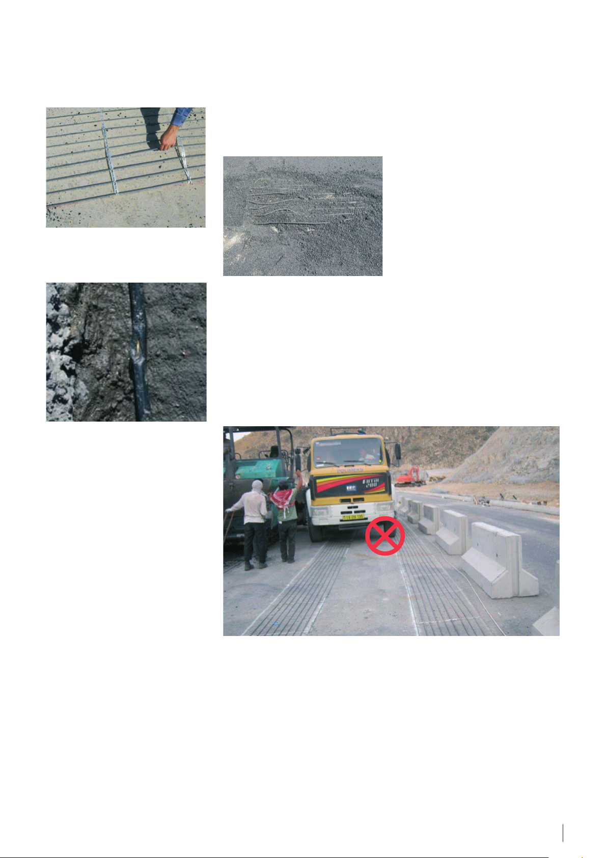
For second layer of asphalt should be
used drum/roller with the maximum
limited load of 500 kg.
It is not allowed to drive directly on
the cables with heavy trucks or asphalt
machinery. It will immediately lead to
cable damages.
5.3.1 Important
All electrical connections must be
done by authorized persons according
to local regulations.
When extending cold lead, observe:
• That there is max. 5% loss of
potential power in the whole length
of the cold cable.
• That the leak current of the whole
installation is less than 1/3 of the
RCD trigger level.
Thermostat controlling ground
temperature is mandatory.
Do not tip the wheel barrow by
supporting it directly on the cables.
Fasten the cables to the subconstruction in short distances to
ensure that the cable remains in right
position.
It is recommended to connect a buzzer
or other alarm giving device to the
cables if an incident anyway should
occur during installation despite all
caution and a cable is being damaged.
Then there will be the ability to quickly
detect this and get the problem solved
at the lowest possible cost and delay.
Application manual · Ground application. Ice & Snow Melting · VGHWD102 · ©Danfoss
17
Page 18

6. Appendixes
A.1. C-C distance and corresponding output W/m²
The C-C distance is a centre-tocentre distance between the cables
(sometimes named installation step or
Cable-to-Cable distance).
When heating cables are installed, we
recommend the use of ECfast fitting
bands. These bands are designed
to ensure a C-C distance at regular
intervals of 2,5 cm, e.g. 5 cm, 7,5 cm, 10
cm, 12,5 cm, etc.
Two different formulas may be used to
calculate the C-C distance:
1) Using heating cable length
Heated floor space [m²] · 100 [cm/m]
C - C [cm] =
Cable length [m]
· 100 cm.
2) Using cable specific output and
output per m²:
C - C [cm] =
Output per m² heated floor space [W/m²]
Cable specific output [W/m] · 100 [cm/m]
C-C distances and corresponding outputs per m² for some linear outputs of heating cables.
Example 1
For a renovation we choose a ECflex 10T
cable (specific output is 10 W/m).
If the chosen output is 120 W/m²,
the calculated by formula no. 2 C-C
distance is:
10 W/m · 100 cm/m
C - C =
120 W/m²
= 8,33 cm.
Example 2
The ECflex 18T, 535 W, 29 m is to be
installed in a bathroom with heated
floor space of 3 m².
The calculated by formula no. 1 C-C
distance is:
3 m² · 100 cm/m
C - C =
29 m
· 100 cm = 10,35 cm.
If we use ECfast fitting bands with
regular intervals of 2,5 cm, we can
install the heating cable in this
bathroom with a C-C 10 cm.
Thermal output of heating surface for several Danfoss heating cables at 230* or 400* V,
C-C
distance,
cm
6 W/m 10 W/m 18 W/m 20 W/m 30 W/m
ECflex 6T
ECflex 10T,
ECbasic 10S
W/m²
ECflex 18T
ECflex 20T,
ECbasic 20S
ECsnow 30T
5 120 200 360 400 600
7,5 80 133 240 270 400
10 60 100 180 200 300
12,5 48 80 144 160 240
15 40 67 120 133 200
17,5 34 57 103 114 170
20 30 50 90 100 150
22,5 26 45 80 89 133
25 24 41 72 80 120
Usually used for Direct floor heating
* The outputs at 220 or 380 V has to be recalculated with the coefficient of 0,91.
Recommended
for Ice and snow
melting and Frost
protection systems
Recommended
for Comfort floor
or Direct heating
systems
Surface heating,
etc.
18
Application manual · Ground application. Ice & Snow Melting · VGHWD102 · ©Danfoss
Page 19

A.2. Fitting
1 m
1 m
1
2
3
4
If we want to calculate the length of
fitting band (e.g. ECfast), first of all
we should determine the distance
between the fitting bands.
For concrete installation, where cable
is covered with 3 cm concrete or more,
and the C-C distance exceeds 10 cm,
the recommended distance between
fitting bands is 0,5 m.
For thin constructions where cable is
covered with 1-2 cm of self-leveling
compound and the C-C distance is
10 cm or less, the max. recommended
distance between fitting bands is
25 cm.
Below is a calculation formula for
C-C distance.
Length of fitting band [m] =
Heated floor space [m²]
=
Distance between fitting bands [m]
[m]
+ L
w
Lw is the length of the wall parallel to
fitting bands installation.
Example
The heated floor space is
1 m x 2 m = 2 m².
If we install ECfast fitting bands in
parallel to a 1 m wall (see fig. 1) and
the distance between the ECfast fitting
bands is 0,5 m, a fitting band with the
following length is required:
2 m²
0,5 m
+ 1 m = 5 m.
If we install ECfast fitting bands in
parallel to a 2 m wall (see fig. 2) and
the distance between the ECfast fitting
bands is 0,5 m, a fitting band of the
following length is needed:
2 m²
0,5 m
+ 2 m = 6 m.
As we can see from this example, the
fitting band length may vary although
the area and the distance between
fitting bands remain the same.
2 m
Fig. 1 - Fitting band installed in parallel
to a 1 m wall.
2 m
Fig. 2 - Fitting band installed in parallel
to a 2 m wall.
Fixing of the heating cable on the ECfast fitting band.
Application manual · Ground application. Ice & Snow Melting · VGHWD102 · ©Danfoss
19
Page 20

A.3. Wire sensor installation
Regardless of the system type it is
always recommended install a ground
wire sensor or integrated ground
moisture and temperature sensor.
Before installation of the outdoor
heating mat or cable, determine
proper location for the connections
(indoor or outdoor) and make
a recession in the wall for the
mounting/connection box. Cut out
the wall groove from the connection
box location down to the ground
for connection cable (cold lead) of
the heating cable and a temperature
sensor conduit.
Wire sensor is usually mounted in a
corrugated plastic pipe with 10-20
mm diameter. The pipe is laid in the
wall grove starting from the mounting
box and along the underlay to the
heating area.
It must be installed within the heating
cable zone, at least 0,5-1 m inside (see
attached picture). The pipe should
enable easy replacement of a wire
sensor (remove-insert) through a hole
in the mounting box.
Where the pipe is bent between the
ground and the wall, the minimum
bending radius is 6 cm (marked R1
in the figure). It is necessary to make
a smooth bend of corrugated pipe
when going from the wall to the
ground.
The pipe end has to be sealed to
avoid concrete penetration inside it
(A mark in the figure). The pipe/sensor
must be positioned in the centre of an
open end of a cable loop and usually
at the same level or slightly above the
heating cables.
If thin heating mat is installed, conduit
pipe has to be laid in a groove so it
does not overhang above the surface.
Groove in the ground is also required
for the cold lead and muff for the
same reason.
Sensor cable can be extended to any
reasonable length, using a cable min.
0,75 mm².
After the wire temperature sensor
is installed it is recommended to
measure resistance.
For information about installation
of integrated ground moisture and
temperature sensor see proper
Installation Instruction.
Power supply cable
Heating cable,
cold lead
R1
To electrical board
Extension cable for sensor
Connection box
Wire sensor
50
Sensor has to be installed between two heating cables and, preferably a bit above their level.
20
Application manual · Ground application. Ice & Snow Melting · VGHWD102 · ©Danfoss
-100 cm
Page 21

A.4. General installation guide
The installation of heating cables
and thermostats should comply with
general and local regulations. The
cables and the thermostats should
only be connected by an authorized
electrician and connected to an RCD.
It is important that the construction
is well insulated according to the
building standards so the downward
heat loss is kept to a minimum.
Rim zone insulation, along the walls,
which should be efficient in order to
prevent heat from being transported
to the foundation walls or adjoining
rooms, and allowing for thermal
expansion of the concrete.
The foundation must be clean and free
of sharp objects.
The cables must never get into contact
with the insulation material or become
enveloped by it in any way.
The cables must be evenly spread on
the available ground and led around
permanently fixed objects such as
bathtubs etc.
The cables must be gently attached so
they are not damaged.
The concrete around the cables must
not contain sharp stones and should
have a consistency enabling it to
surround the cable completely without
leaving air pockets.The concrete
should be applied very carefully in
order not to damage the heating
cables!
A damp proof membrane is needed
to prevent moisture from moving
upwards and into the construction.
The wire of the ground sensor must be
protected by a plastic pipe.
The wire sensor must be positioned in
the centre at an open end of a cable
loop. Where the pipe is bent between
the ground and the wall, the minimum
bending radius is 6 cm.
The pipe must be sealed at the end
to prevent concrete from entering.
Should the cable become damaged
while being laid out or later during the
building process, it is a great advantage
in the fault finding process to know
the exact positioning of the the
connection box between the heating
cable and the cold cable as well the
cable end, and the cable layout. It is
therefore important to make a sketch
showing the positioning of these
things in the room.
Heating cable and wire sensors
resistance needs to be measured
before, during and after installation
of concrete, before thermostat is
connected.
The heating cable and the connection
muff between the heating cable and
the cold cable must both be cast in
concrete. If the cable is pushed down
into the insulation material or covered
by it in any other way, the surface
temperature may become too high,
that might result in cable defects at
worst.
At low temperatures (below 5 °C) the
cable can become difficult to handle
due to the plastic sheath. This problem
can be overcome by connecting
the cables for a short period. For
this purpose THE CABLE MUST BE
ROLLED OUT! When the cable has
become flexible again, the electrical
flow should be disconnected. It is
not recommended to lay cables at
temperatures below -5 °C.
The ground heating must not be
turned on before the concrete has fully
set. It takes approximately 30 days for
concrete and usually
10-15 days for molding compound,
tile glue etc. (it is important to
comply carefully with manufacturer’s
recommendations).
Keep a min. 5 cm air gap beneath
permanent objects and ground surface
with installed heating.
To ensure an accurate and easy
installation of the cables, ECfast fitting
bands can be used.
The ECfast fitting bands are equipped
with attachment clips at intervals of 2,5
cm so the distance between the cable
loops will be
5, 7,5, 10, 12,5, 15, etc.
Concrete must be laid out in such a way
to avoid air pocket inside it.
In connection with wet rooms
(bathrooms etc.) a damp proof
membrane should always be used
in order to prevent moisture from
entering the construction.
Application manual · Ground application. Ice & Snow Melting · VGHWD102 · ©Danfoss
21
Page 22

Notes
22
Application manual · Ground application. Ice & Snow Melting · VGHWD102 · ©Danfoss
Page 23

Notes
Application manual · Ground application. Ice & Snow Melting · VGHWD102 · ©Danfoss
23
Page 24

7. Cases
ROZADOL BRATISLAVA
Bratislava, Slovakia
Purpose of the Danfoss system:
Ice and snow melting on driveway in
underground garage.
Project size:
400 m².
Products:
• ECflex 18T;
• EFIT 850.
CINEPLEXX CINEMA,
Hohenems, Austria.
Purpose of the Danfoss system:
Outdoor heating of the stairs to the
entrance.
Project size:
89 m² area heated with 86 pcs. mats.
Products:
• ECsnow 30T, 400 V;
• EFIT 850 + Ground sensor.
© Copyright Danfoss | Dec 23, 2016VGHWD102
 Loading...