

Page 1
Instructions
GPS 40-150
Installation
148R9546
Fig. 1
Fig. 2a
GPS 100-150
Fig. 2b
148R9546
GPS 40-80
DN 40-50 = 40 30
DN 65-80 = 40 30
DN 100 = 70 52
DN 125 = 150 110
Fig. 3
ENGLISH
Refrigerants
R717 (ammonia)), R22, R134a, R404A,
R407, R407B, R407C, R744.
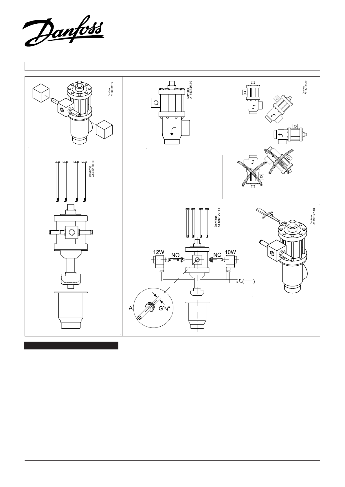
Installation
GPS valves in sizes DN 100 to DN 150 are
always installed in vertical position fig. 2a.
GPS valves in other sizes are installed as
shown in fig. 2b, i.e. in 90° from vertical
position with pilot valve and side branch
downwards. If there is welding slag and/or
dirt in the system, it is strongly recommended to install strainers in connection with
the GPS valve.
It is important always to install strainers in
the pipes leading to the pilot valves.
© Danfoss A/S (MR-MC/MWA), 09-2008 DKRCI.PI.KN0.A1.7G / 520H3076 1
Fig. 4a
Flow direction
IMPORTANT: The flow direction must be
from the side branch towards the cone
(fig. 2a+2b).
Welding
Remove the actuator before welding (fig.
3). OBS: Be sure not to damage the
teflon cone ring and the spindle. If
these parts are damaged the valve
will leak.
Assembling
Remove welding slag and dirt from pipes
and housing. The valve cone is protected
with a cap. (B) Remove this cap before
the valve is assembled (fig.3). OBS: Only
1 hot gas supply is required (Cf. Illustration
A on fig. 4a); connect this supply to the
pilot valve armature.
Tightening
Use a torque wrench to tighten the 8 bolts
connecting the housing with the actuator.
Tighten the bolts in accordance with the
table fig. 4b.
Manual opening
For instance by failure of current, see
instruction overleaf.
Colours
In factory the valve housings are painted in
a oxide yellow primer. The actuator is
metallized.
DN 150 = 300 220
Fig. 4b
Nm ft. lb.
Page 2

Instructions - GPS 40-150
DANSK DEUTSCH
Kølemidler
R717 (ammoniak), R22, R134a, R404A,
R407, R407B, R407C, R744.
Installation
GPS ventiler i størrelse DN 100 til DN
150 må kun monteres lodret fig. 2a.
GPS ventiler i de øvrige størrelser monteres
som vist i fig. 2b, d. v. s. i en position
fra lodret til 90° fra lodret position med
pilotventilen og sidestuds nedad. I
rørsystemer med svejsesprøjt og snavs
anbefales det, at der installeres filtre i
forbindelse med GPS ventilen. Der bør
altid installeres filtre i rør, der leder til en
magnetventil.
Strømningsretning
VIGTIGT: Strømningsretningen skal være
fra sidestuds og ned mod keglen (fig.
2a+b).
Svejsning
Aktuatoren skal afmonteres før isvejsning
af ventilhuset (fig. 3). OBS: Teflonringen
på keglen og spindlen må ikke beskadiges.
Beskadigelse af disse dele vil forårsage
utætheder i ventilen.
Samling
Svejsesprøjt og snavs skal ernes fra rør
og hus. Ventilkeglen er beskyttet med en
hætte. (B) Denne ernes inden ventilen
samles (fig. 3). OBS: Der kræves kun 1 varmgastilførsel, der tilsluttes magnetventilens
armatur (Jvf. illustration A på fig. 4a).
Tilspænding
De 8 bolte, der forbinder aktuatoren med
ventilhuset, spændes med en momentnøgle iht. fig. 4b.
Manuel tvangsåbning
F. eks. ved strømsvigt se vejledning på
omstående side.
Farve
Ventilhusene er fra fabrikken malet med
en oxydgul primer. Aktuatoren er metaliseret.
Kältemittel
R717 (Ammoniak), R22, R134a, R404A,
R407, R407B, R407C, R744.
Montage
Das GPS Ventil in Dimensionen DN 100
bis DN 150 muss nur in senkrechter
Position installiert werden Fig. 2a. GPS
Ventile in übrigen Dimensionen werden
wie in Fig. 2b gezeigt montiert, d.h. in
einer Position von senkrecht bis 90° von
senkrechter Position mit dem Pilotventil
und Seitenstutzen abwärts. In Rohrsystemen mit Schweißschlacken und
Schmutz empfiehlt es sich, Filter im
Anschluß an das GPS Ventil zu installieren.
In Rohren, die zu einem Magnetventil
führen, müssen immer Filter installiert
werden.
Strömungsrichtung
WICHTIG: Die Strömungsrichtung wie auf
der Zeichnung angegeben (Fig. 2a+2b) d.h. von dem Seitenstutzen zum Kegel
hinab.
Schweißen
Den Antrieb vor dem Einschweißen des
Ventilgehäuses demontieren (Fig. 3).
Achtgeben, daß weder Teflonkegelring
noch Spindel beschädigt werden,
was Undichtigkeiten zur Folge haben
wird.
Sammlung
Schweißschlacken und Schmutz von
Rohren und Gehäuse entfernen. Der
Ventilkegel ist mit einer Schutzkappe (B)
versehen. Diese Kappe vor Sammlung des
Ventils entfernen. OBS: Nur 1 Heißgaszuleitung ist erforderlich (vgl. Illustration A
der Figur 4a); diese Zuleitung ist an die
Armatur der Magnetventile anzuschließen.
Zuspannung
Verwenden Sie einen Drehmomentschlüssel, um die 8 Schrauben, die das
Gehäuse mit dem Antreib verbinden, laut
Fig. 4b festzuziehen .
Manuelle Zwangsöffnung
Zum Beispiel bei Stromausfall - siehe
Anleitung umstehend.
Farben
Die Ventilgehäuser werden in der Fabrik
mit oxydgelbem Grundierungsanstrich
versehen. Der Antrieb wird metallisiert.
ESPAÑOL
Refrigerantes
R717 (Amoniaco), R22, R134a, R404A,
R407, R407B, R407C, R744.
Instalación
Válvulas GPS en dimensiones DN 100
hasta DN 150 deben instalarse solamente
en posición vertical (fig. 2a).
Válvulas GPS en otras dimensiones se
deben sinstalar como ilustrado en la fig.
2b, o sea en una posición entre vertical y
90° de tal posición con la válvula piloto y
el racor lateral hacia abajo. En tuberias
con escorias y suciedades de soldadura se
recomienda la instalación de filtros en
conexión con la válvula GPS. Siempre
debe instalarse filtros en tubos que
conducen a una válvula de accionamiento
magnético.
Sentido de la corriente
IMPORTANTE: El Sentido de la corriente
tiene que ser como indicado en el dibujo
(fig. 2a+2b) o sea desde el racor lateral
hacia el cono.
Soldadura
Hay que desmontar el actuador antes de
soldar la caja de la válvula (fig. 3). NOTA:
No dañar el anillo de teflon del cono y
del vástago. Si estas partes se dañan,
habrá fugas en la válvula.
Montaje
Quitar escorias y suciedades de soldadura
en los tubos y la caja. El cono de la válvula
está protegido por una capucha (B) que se
quita antes de montar la válvula (fig. 3).
NOTA: Sólo se requiere un suministro
de gas caliente que se conecta a la
armadura de las válvulas piloto de
accionamiento magnético (Véase la
ilustración A de fig. 4a).
Apriete
Utilizar una llave dinamométrica para
apretar los 8 pernos de conexión del
cuerpo con el servo (fig. 4b).
Apertura manual forzada
Por ejemplo en caso de apagón (véase
instrucción a la vuelta).
Color
Los cuerpos de las válvulas GPS salen de la
fábrica tratados con una pintura de fondo
de color amarillo de óxido. El actuador
está metalizado.
2 DKRCI.PI.KN0.A1.7G / 520H3076 © Danfoss A/S (MR-MC/MWA), 09-2008
Page 3
Instructions - GPS 40-150
Maintenance
Type 112
DN 40-50 = 80 60
DN 65-80 = 120 89
DN 100 = 140 103
DN 125 = 170 125
DN 150 = 170 125
Fig. 5a
Nm ft. lb.
DN 40-50 = 100 74
DN 65-80 = 130 96
DN 100 = 170 125
DN 125 = 170 125
DN 150 = 170 125
Type 111/114
ENGLISH
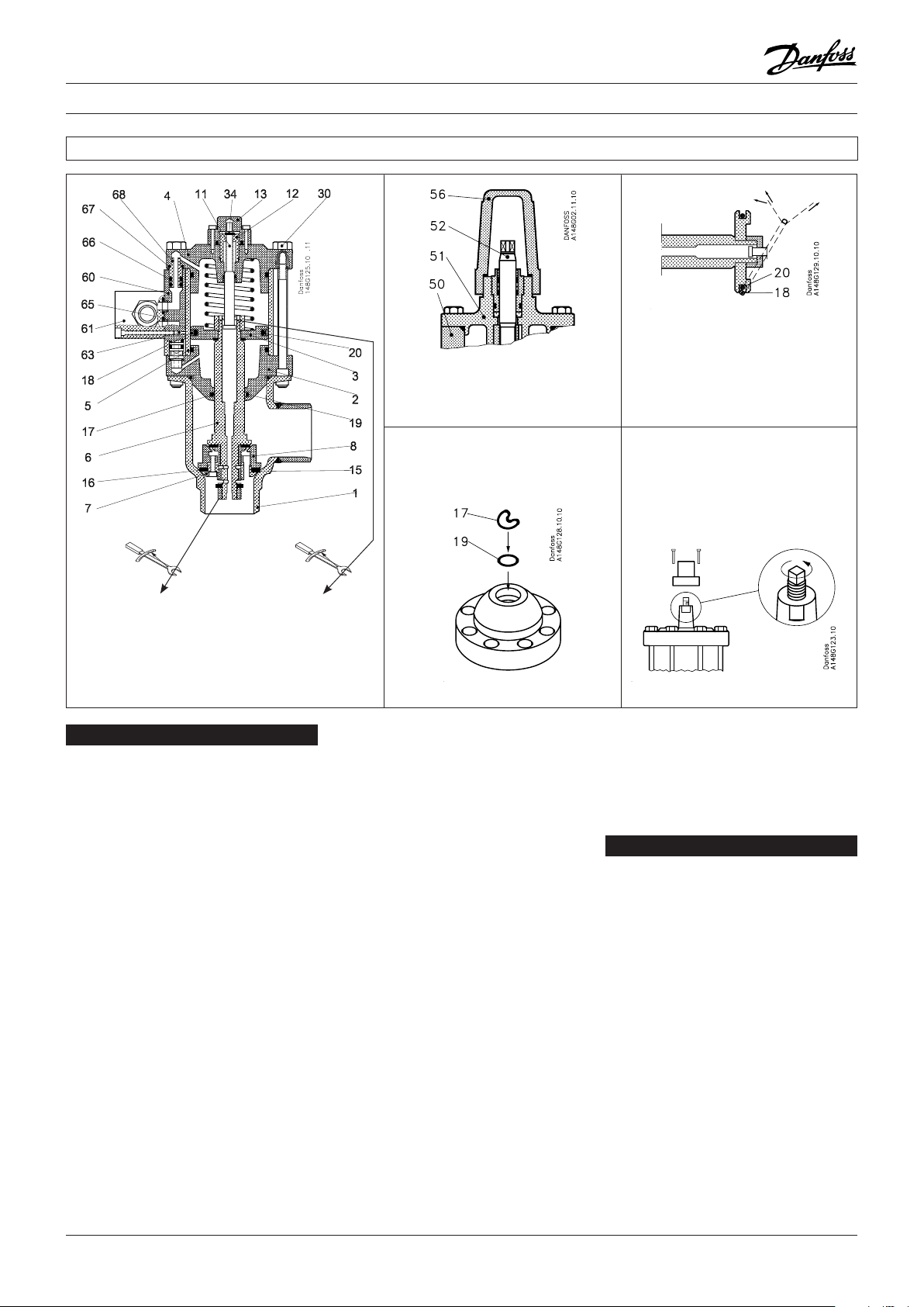
Replacement of sealing elements
Disassembling of GPS
Evacuate the pipe system in which the
valve is installed. Switch off the pilot
current and the hot gas supply. Remove
the bolts (30). Remove the valve top
(actuator).
Replacement of teflon rings in the seat
(15) and (16)
Remove the nut (32), the valve cone (7)
and (8), and remove the bushing (9).
Replace the Teflon rings (15) and (16) and
assemble the parts in reverse order.
Replacement of sealing rings
(17) and (18)
A. Remove the cap (13) and the lock ring
(34). Unscrew the spindle (11) clockwise
till it is disengaged from the thread.
B. Remove the bolts (28), the top cover
(4), the pilot block (60), the spring
(10), the cylinder pipe (5) and the pilot
connections (68).
C. Loosen the lock screw (26), remove the
nut (14), the piston (3), and the valve
spindle (6). - NB: Handle the valve
spindle very carefully, as any damage
(e.g. scratches and marks) to the spindle
may cause valve leakage.
Fig. 5b
Nm ft. lb.
Fig. 6
D. Remove the sealing rings (17) and (18).
At renovation of the valve Danfoss
recommends replacement of all sealing
elements. The spare parts set for the
GPS valves includes all sealing
elements.
E. Mount the O-ring (19) and then the
sealing ring (17) as shown in fig 6.
Important:
Fold the sealing ring as shown. Be
certain that there are no sharp folds
and do not use tools to mount the
sealing ring.
F. Mount the O-ring (20) and then the
sealing ring (18) as shown in fig 7. In
order not to damage the ring use 2
plastic strips to pull the ring to the right
place.
G. Mount the O-rings (66) on nipples for
the pilot connection. Mount the nipples
(68) with the gaskets (67), tighten
30-35 Nm.
Reassemble the actuator in reverse
order: C-B-A.
NB.
Turn the piston (3) as shown on fig. 5a.
Manual opening
In case of power loss the GPS valve will
close (NC). The valves without forced
Fig. 7
Fig. 8
closing device can be opened by hand,
if the cap is removed and the spindle is
turned anti-clockwise. To close the valve,
turn the spindle clockwise.The spindle
must be screwed to the lowest possible
position during normal operation (fig. 8).
DANSK
Udskiftning af tætningselement
Adskillelse af GPS
Rørsystemet, hvori ventilen er monteret,
evakueres. Styrestrøm og varmgastilførsel
afbrydes. Fjern boltene (30). Ventiltoppen
ernes.
Udskiftning af sædepakning (15) og (16)
Fjern møtrikken (32), ventilkeglen (7) og
(8) og bøsningen (9). Udskift teflonringene
(15) og (16) og monter delene i modsat
rækkefølge.
Udskiftning af tætningsring (17) og (18)
A. Fjern hætten (13) og låseringen (34).
Spindlen (11) skrues med uret indtil
den ikke har indgreb i gevindet
længere.
B. Fjern boltene (28), topdækslet (4),
pilotblokken (60), ederen (10),
cylinderrøret (5) og pilotforbindelserne
(68).
C. Løsn låseskruen (26), ern møtrikken
(14), stemplet (3) og stempelstangen
3 DKRCI.PI.KN0.A1.7G / 520H3076 © Danfoss A/S (MR-MC/MWA), 09-2008
Page 4

Instructions - GPS 40-150
(6). NB: Behandl stempelstangen meget
varsomt, da ridser og mærker kan
forårsage lækager i ventilen.
D. Fjern tætningsringene (17) og (18). Ved
renovering af ventilen anbefaler
Danfoss, at samtlige tætningselementer
udskiftes. GPS reservedelssættet inde holder samtlige tætningselementer.
E. Montér O-ringen (19) og tætnings-
ringen (17), som vist på fig. 6. Vigtigt:
Fold tætningsringen som vist. Der må
ikke være “skarpe knæk” på ringen, og
der må ikke anvendes værktøj til
montagen.
F. Monter O-ringen (20) og derefter
tætningsringen (18) som vist på fig. 7.
Undgå at beskadige ringen ved at
anvende 2 plasticstrimler til at trække
ringen på plads.
G. Monter O-ringene (66) på niplerne til
pilotforbindelserne. Monter så niplerne
(68) med pakningerne (67), spænd med
30-35 Nm.
Saml aktuatoren i modsat rækkefølge:
C-B-A.
OBS:
Vend stemplet (3) som vist på fig. 5a.
Manuel tvangsåbning
Ved strømsvigt lukker GPS ventilen (NC).
Ventilerne uden tvangslukningsmekanisme
kan åbnes ved håndkraft, hvis hætten
ernes, og spindlen drejes mod uret.
Ventilen lukkes ved at dreje spindlen med
uret. Spindlen skal være skruet i lavest
mulige position under normal drift (fig. 8).
DEUTSCH
Austausch der Dichtungselemente
Demontage des GPS
Evakuieren Sie das Leitungsrohr, an dem
das Ventil installiert ist. Schalten Sie den
Steurungsstrom sowie die Heißgasversorgung ab. Entfernen Sie Die
Schrauben (30). Entfernen Sie die Membrankammer (Stellglied-element).
Austausch der Teflonringe im sitz
(15) und (16)
Entfernen Sie die Mutter (32), den
Ventilkegel (7) und (8) sowie die Buchse
(9). Ersetzen Sie die Teflonringe (15)
und (16) und setzen Sie die Teile in
der umgekehrten Reihenfolge wieder
zusammen.
Austausch der Dichrungsringe
(17) und (18)
A. Enfernen Sie die Kappe (13) und den
Verschlußring (34). Schrauben Sie die
Spindel (11) so lange im Uhrzeigersinn
bis sie vom Gewinde gelöst ist.
B. Entfernen Sie die Schrauben (28), den
oberen Deckel (4), der Pilotblock (60),
die Feder (10), das Zylinderrohr (5) und
die Pilotanschlüße (68).
C. Lockern Sie die Verschlußschraube (26)
und entfernen Sie die Mutter (14), den
Kolben (3) und die Ventilspindel (6).
-P.S.: Behandeln Sie die Ventilspindel
sehr vorsichtig, da jegliche Beschä-
digung (z.B. Kratzer und Stellen) der
Spindel zu Ventilleckagen führen
können.
D. Entfernen Sie die Dichtungsringe (17)
und (18). Danfoss empfiehlt, alle
Dichtungselemente bei Wiederauf-
bereitung des Ventils zu ersetzen. Das
Ersatzteilset für die GPS-Ventile enthält
alle Dichtungselemente.
E. Montieren Sie den O-ring (19) und
danach den Dichtungsring (17), siehe
hierzu Abb. 6. Wichtig: Falten Sie den
Dichtungsring wie abgebildet. Achten
Sie darauf, daß keine scharfen Knicke
entstehen und verwenden Sie keine
Werkzeuge um den Dictungsring zu
montieren.
F. Montieren Sie den O-ring (20) und
danach den Dichtungsring (18), siehe
hierzu Abb. 7. Verwenden Sie 2
Plastikstreifen um den Ring an die
richtigeStelle ziehen, damit Sie den
Ring nicht verletzen.
G. Montieren Sie die O-ringe (66) auf die
Nippel für den Pilotanschluß. Die
Nippel (68) mit den Dichtungen (67)
montieren, 30-35 Nm anziehen.
Setzen Sie das Stellgliedelement in der
umgekehrten Reihenfolge: C-B-A
wieder zusammen.
WICHTIG:
Den stempel (3) wie auf fig. 5a. gezeigt
montieren.
Zwangsöffnung
Beim Stromausfall schließt das GPS Ventil
(NC). Die Ventile ohne Zwangsverschluss
können manuell geöffnet werden, indem
die Kappe entfernt und die Spindel
entgegen dem Uhrzeigersinn gedreht
wird. Um das Ventil zu schließen, muß die
Spindel im Uhrzeigersinn gedreht werden.
Während Normalbetriebes muß die Spindel
bis zur untersten Position eingeschraubt
werden (Fig. 8).
ESPAÑOL
Sustitucion de los elementas del prensa
Desmontaje de GPS
Vaciar el sistema de tuberias en el que la
válvulas se encuentra instalada. Desconectar la tensión piloto y el suministro de gas
caliente. Desmontar los pernos (30).
Desmontar la parte superior de la válvula
(servo).
Sustitucion de los aros de teflon del
asiento (15) y (16)
Desmontar la tuerca (32), los conos del
asiento (7) y (8) el casquillo (9). Sustituir los
aros de teflon (15) y (16) y montar las
piezas en el orden inverso.
Sustitucion de los toricos (17) y (18)
A. Desmontar la caperuza (13) y el aro de
fi-jación (34). Desatornillar el vástago
(11) en el sentido de las agujas del reloj
hasta que se salga de la rosca.
B. Desmontar los pernos (28), la tapa
superior (4), blogue de piloto (60),el
resorte (10), el tubo distanciador (5) y
las conexiónes de piloto (68).
C. Aflojar la tuerca de fijación (26),
desmontar la tuerca (14), el pistón (3 y
el vástago de la válvula (6). - Nota:
Manejar el vástago de la válvula con
mucho cuidado, ya que cualquier daño
sobre el, (rayaduras, marcas, etc.)
podrian ser la causa de fugas.
D. Desmontar los aros (17) y (18).
Recomendamos sustituir los aros
tõricos de la válvula. El juego de
repuestos para las válvulas GPS, incluye
todos los aros tóricos de la misma.
E. Montar el aro tórico (19) y el aro (17)
tal como se indica en la figura 6.
Importante: Doblar el aro tal como se
muestro en dicha figura. Asegurarse de
que el aro no sufre dobleces bruscas y
no utilizar herramientas para montarlo.
F. Montar el aro tórico (20) y después el
aro (18) tal como se indica en la figura
7. Para situar el aro en su posición
correcta utilizar dos regletas de
plástico, evitando con ello la
possibilidad de dañarlo.
G. Montar los aros tóricos (66) en los
racores para las conexiónes de piloto.
Montar los racores (68) con las
guarniciónes (67), apretar 30-35 Nm.
Montar el servo en el orden: C-B-A.
NOTA:
Colocar el pistón (3) como indicado en
la fig. 5a.
Apertura manual
En caso de corte de corriente, se cierra la
válvula GPS (NC). Las válvulas sin
dispositivo de cierre forzado pueden
abrirse con la mano, desmontando la
caperuza y haciendo girar el vástago en el
sentido contrario a las agujas del reloj. La
válvula se cierra girando el vástago en el
sentido de las agujas del reloj. El vástago
debe estar apretado en la posición más
baja posible durante el funcionamiento
normal (fig. 8).
4 DKRCI.PI.KN0.A1.7G / 520H3076 © Danfoss A/S (MR-MC/MWA), 09-2008
 Loading...