

Page 1
Installation Guide
2-step solenoid valve
GPLX
Installation
148R9 513
1 2
148R9 513
G ¼”
A
3 4
© Danfoss A/S (MWA), 2015-03 DKRCI.PI.BO0.A4.02 / 520H4693 1
Page 2
Maintenance
Pos. 4 Nm LB-feet
DN 80 50 37
DN 100 100 74
DN 125-150 130 96
Pos. 20 Nm LB-feet
DN 80-100 100 74
DN 125-150 145 106
Pos. 24 Nm LB-feet
DN 80 44 32
DN 100 75 55
DN 125-150 183 135
5 6
7 8
2 DKRCI.PI.BO0.A4.02 / 520H4693 © Danfoss A/S (MWA), 2015-03
Page 3

ENGLISH
Installation
Application
The GPLX valves are specially designed for
evaporator return lines. The GPLX valve
enables the evaporator to be defrosted
when closed. It also ensures a proper and
safe equalization of the evaporator before
reaching its fully open position upon
defrost sequence completion.
Note:
Since GPLX valves remain closed while
de-energized, the valves must not be used
for applications where seat tightness is
essential over a long period of time (a small
leak-by rate when closed may occur).
Refrigerants
Applicable to HCFC, HFC, R717 (Ammonia)
and R744 (CO2).
Flammable hydrocarbons are not
recommended. The valves are only
recommended for use in closed circuits.
For further information please contact
Danfoss.
Temperature range
GPLX: –60º/+150ºC (–76º/+302ºF)
Pressure range
GPLX: The valves are designed for a max.
working pressure of 40 bar g (580 psi g).
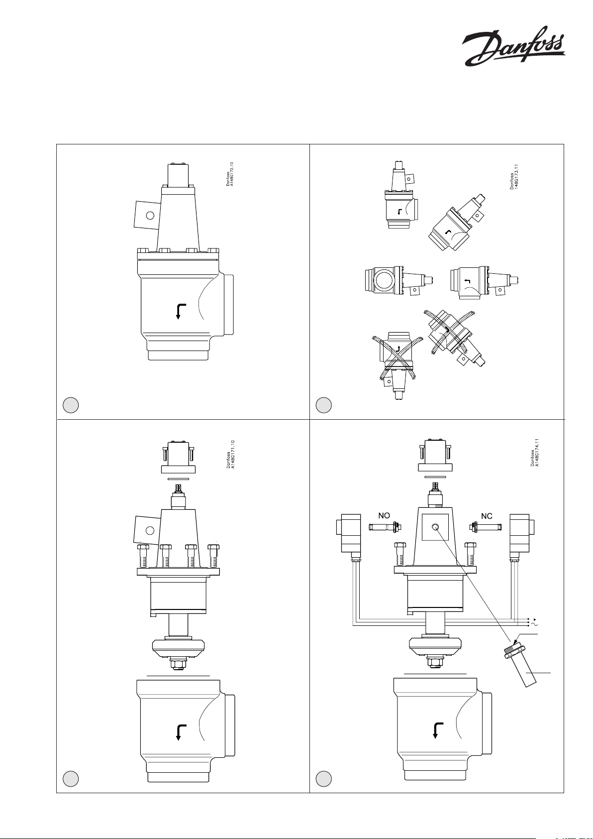
Installation
GPLX valves in sizes DN 80 to DN 150 can
be installed as shown in g. 2, i.e. in 90º
from vertical position with pilot valve
and side branch downwards. If there is
welding slag and/or dirt in the system, it is
strongly recommended to install strainers
in connection with the GPLX valve.
The valve is designed to withstand a high
internal pressure. However, the piping
system should be designed to avoid liquid
traps and reduce the risk of hydraulic
pressure caused by thermal expansion. It
must be ensured that the valve is protected
from pressure transients like “liquid
hammer” in the system.
It is important always to install strainers
in the pipes leading to the pilot valves.
Recommended ow direction (Fig. 1)
Important:
The ow direction must be from the side
branch towards the cone.
Welding (Fig. 3)
Remove the actuator before welding to
prevent damage to the gasket (pos. 17)
between the valve body and bonnet, as
well as the teon gasket (pos. 18, 19) in
the valve seat. Only materials and welding
methods, compatible with the valve
housing material, must be welded to the
valve housing.
The valve should be cleaned internally to
remove welding
debris on completion of welding and
before the valve is reassembled.
Avoid welding debris and dirt in the
threads of the housing and the bonnet.
Removing the bonnet can be omitted
provided that:
The valve housing must be free from
stresses (external loads) after
installation.
OBS: Be sure not to damage the
teon gasket (pos. 18, 19) and the
spindle surface (pos. 3). If these parts
are damaged the valve will leak.
Removing the bonnet can be omitted
provided that:
The temperature in the area between the
valve body and bonnet during welding
does not exceed +150°C/+302°F. This
temperature depends on the welding
method as well as on any cooling of the
valve body during the welding itself.
(Cooling can be ensured by, for example,
wrapping a wet cloth around the valve
body.) Make sure that no dirt, welding
debris etc. get into the valve during the
welding procedure.
Be careful not to damage the gasket (pos.
17).
The valve housing must be free from
stresses (external loads) after installation.
GPLX valves must not be mounted in
systems where the outlet side of the valve
is open to atmosphere. The outlet side of
the valve must always be connected to the
system or properly capped o, for example
with a welded-on end plate.
Assembly (Fig. 5)
Remove welding slag and dirt from pipes
and valve body.
OBS: Only 1 hot gas supply is required
(Pos. A on g. 4); connect this supply to
the pilot valve armature.
Colours and identication
The GPLX valves are painted with a
yellow oxide primer in the factory and the
external actuator top is zinc-chromated.
Precise identication of the valve is made
via the ID plate (pos. 41) at the top of the
cap (pos. 12), as well as by the stamping on
the valve body. The external surface of the
valve housing must be prevented against
corrosion with a suitable protective coating
after installation and assembly.
Protection of the ID plate when repainting
the valve is recommended.
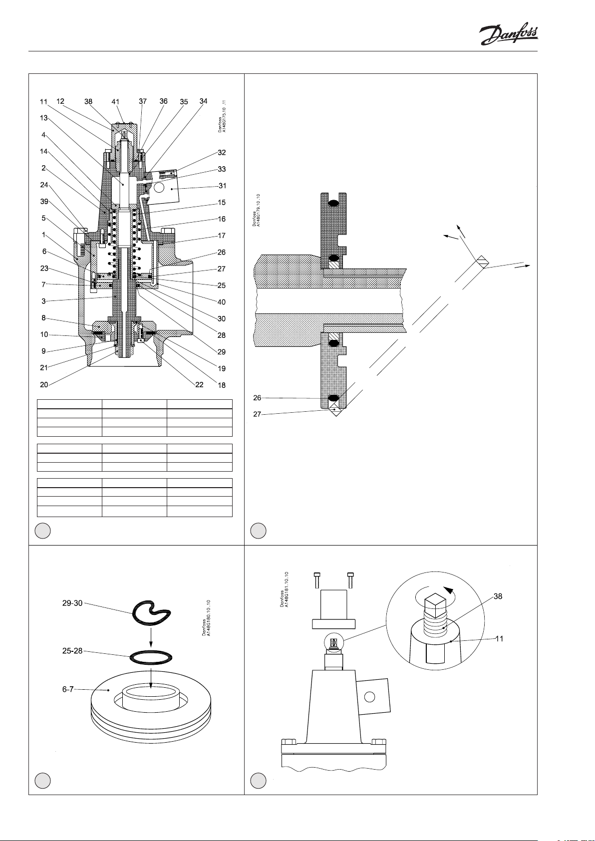
Maintenance
Replacement of sealing elements disassembling of GPLX
Evacuate the pipe system in which the
valve is installed. Switch o the pilot
current and the hot gas supply. Remove
the bolts (pos. 24). Remove the valve top
(actuator).
Replacement of teon rings in the seat
(Pos. 18 and pos. 19)
Remove the nut (pos. 20), the screw (pos.
22), the valve cone (pos. 8 and pos. 10), and
remove the bushing (pos. 9).
Replace the Teon rings (pos. 18) and (pos.
19) and assemble the parts in reverse order.
Replacement of sealing rings (pos. 27),
(pos. 29) and (pos. 30)
A. Remove the cap (pos. 12) and the lock
ring (pos. 38). Unscrew the spindle (pos.
13) clockwise till it is disengaged from
the thread.
B. Unscrew the bolts (pos. 23), Pull
the spindle (pos. 3) out of the
valve top. Unscrew the bolt (pos. 4)
counterclockwise. Remove the springs
(pos. 15 and 16) and the spindle (pos.
13) and bushing (pos. 14). Pull out the
piston (pos. 6) and guide (pos. 7)
C. NB: Handle the valve spindle very
carefully, as any damage (e.g. scratches
and marks) to the spindle may cause
valve leakage.
D. Remove the sealing rings (pos. 27, 29
and 30).
At renovation of the valve Danfoss
recommends replacement of all
sealing elements. The spare parts set
for the GPLX valves includes all sealing
elements.
E. Mount the O-ring (pos. 25, 28) and then
the sealing ring (pos. 29, 30) as shown in
g 7. Important:
Fold the sealing ring as shown. Be
certain that there are no sharp folds and
do not use tools to mount the sealing
ring.
F. Mount the O-ring (pos. 26) and then the
sealing ring (pos. 27) as shown in g 6.
In order not to damage the ring use 2
plastic strips to pull the ring to the right
place.
G. Reassemble the actuator in reverse
order: C-B-A. NB. Turn the piston (pos. 6)
as shown on g. 5.
Manual opening (Fig. 8)
In case of power loss the GPLX valve
will close (NC). The valve can be opened
by hand, if the cap (pos. 12) is removed
and the spindle (pos. 13) is turned anticlockwise. To close the valve, turn the
spindle (pos. 13) clockwise.
© Danfoss A/S (MWA), 2015-03 DKRCI.PI.BO0.A4.02 / 520H4693 3
Page 4

The spindle (pos. 13) must be screwed
to the lowest possible position (contact
between spring ring (pos. 38) and thread
bushing (pos. 11) during normal operation.
Tightening (Fig. 4)
Tighten the bonnet with a torque wrench,
to the values indicated in the table.
Use only original Danfoss parts, O-rings
and gaskets for replacement. Materials of
new parts are certied for the relevant
refrigerant. In cases of doubt, please
contact Danfoss.
Danfoss accepts no responsibility for
errors and omissions. Danfoss Industrial
Refrigeration reserves the right to make
changes to products and specications
without prior notice.
4 DKRCI.PI.BO0.A4.02 / 520H4693 © Danfoss A/S (MWA), 2015-03
 Loading...