

Page 1
Technical Information
Gear Motors
Group 1, 2, and 3
www.danfoss.com
Page 2

Technical Information
G
ear Motors Group 1, 2, and 3
Revision history Table of revisions
Date Changed Rev
July 2021 Minor corrections to data made 0102
October 2019 First edition 0101
2 | © Danfoss | July 2021 BC319483612502en-000102
Page 3

Technical Information
G
ear Motors Group 1, 2, and 3
Contents
General information
Overview..............................................................................................................................................................................................
Features and benefits..................................................................................................................................................................... 7
Motor displacements...................................................................................................................................................................... 7
Determination of nominal motor size.......................................................................................................................................8
System Requirements
Pressure................................................................................................................................................................................................9
Speed....................................................................................................................................................................................................9
Hydraulic Fluids.............................................................................................................................................................................. 10
Temperature and Viscosity.........................................................................................................................................................10
Filtration............................................................................................................................................................................................ 11
Line sizing-x..................................................................................................................................................................................... 12
Motor shaft connection............................................................................................................................................................... 12
Motor shaft load data form........................................................................................................................................................ 13
Motor Life..........................................................................................................................................................................................13
Group 1 Gear motors
Motor design................................................................................................................................................................................... 14
Technical data................................................................................................................................................................................. 15
Model code.......................................................................................................................................................................................15
Motor performance graphs........................................................................................................................................................19
Flange, shaft and port configurations....................................................................................................................................22
Shaft options....................................................................................................................................................................................22
Integral relief value - SKM1IN.....................................................................................................................................................23
Ports dimensions............................................................................................................................................................................26
Dimensions.......................................................................................................................................................................................27
Group 2 Gear motors
Motor design................................................................................................................................................................................... 31
Technical data................................................................................................................................................................................. 32
Model code.......................................................................................................................................................................................33
5
Filters.............................................................................................................................................................................................11
Selecting a filter.........................................................................................................................................................................11
Reservoir...................................................................................................................................................................................... 11
A Family........................................................................................................................................................................................15
B Displacement..........................................................................................................................................................................16
C Rotation....................................................................................................................................................................................16
D Project version ......................................................................................................................................................................16
E Mounting flange....................................................................................................................................................................16
F Drive Gear................................................................................................................................................................................ 16
G Rear cover................................................................................................................................................................................17
H Inlet size; I Outlet size..........................................................................................................................................................17
J Ports Pos & Spec Body..........................................................................................................................................................18
K Seals........................................................................................................................................................................................... 18
L Screws........................................................................................................................................................................................18
M Set valves................................................................................................................................................................................ 18
N Type of mark...........................................................................................................................................................................19
O Mark position.........................................................................................................................................................................19
Variant codes for ordering intergral relief valve............................................................................................................24
SKM1NN, SKU1NN, SNU1NN – 01BA..................................................................................................................................28
SKM1NN, SKU1NN – 02BB, 02FA......................................................................................................................................... 29
SKM1NN, SKU1NN – 06GA and 06SA.................................................................................................................................30
SNM2NN.......................................................................................................................................................................................31
SNU2NN....................................................................................................................................................................................... 31
SKU2NN........................................................................................................................................................................................32
A Family........................................................................................................................................................................................33
B Displacement..........................................................................................................................................................................34
C Rotation....................................................................................................................................................................................34
D Project version ......................................................................................................................................................................35
E Mounting flange....................................................................................................................................................................35
©
Danfoss | July 2021 BC319483612502en-000102 | 3
Page 4

Technical Information
G
ear Motors Group 1, 2, and 3
Contents
Motor performance graphs........................................................................................................................................................40
Flange, shaft and port configurations....................................................................................................................................42
Shaft options....................................................................................................................................................................................43
Port dimensions..............................................................................................................................................................................44
Integral relief valve - SNM2IN.................................................................................................................................................... 46
Anti-cavitation check valve - SNM2GN...................................................................................................................................49
Integral relief valve and anti-cavitation check valve - SNM2JN.................................................................................... 49
Outrigger bearing assembly - SNM2NN................................................................................................................................ 50
Dimensions.......................................................................................................................................................................................55
Group 3 Gear motors
Motor design................................................................................................................................................................................... 60
Technical data................................................................................................................................................................................. 61
Model code.......................................................................................................................................................................................62
Motor performance graphs........................................................................................................................................................67
Flange, shaft, and port configurations...................................................................................................................................70
Shaft and flange availability.......................................................................................................................................................71
Ports dimensions............................................................................................................................................................................72
Anti-cavitation check valve - SNM3GN...................................................................................................................................75
Dimensions.......................................................................................................................................................................................76
F Drive gear.................................................................................................................................................................................35
G Rear cover................................................................................................................................................................................
H Inlet size; I Outlet size..........................................................................................................................................................37
J Ports pos & Spec body......................................................................................................................................................... 38
K Seals........................................................................................................................................................................................... 38
L Screws........................................................................................................................................................................................38
M Set valves................................................................................................................................................................................ 38
N Type of mark...........................................................................................................................................................................39
O Mark position.........................................................................................................................................................................39
Variant codes for ordering intergral relief valve............................................................................................................47
Allowable shaft loads.............................................................................................................................................................. 51
Outrigger bearings 9A, 94, 9J, 9F, and 9H .......................................................................................................................53
Dimensions............................................................................................................................................................................54
SNM2NN, SNU2NN – 01DA, 01FA and 01BA...................................................................................................................55
SNM2NN, SNU2NN – 02DB and 02AA............................................................................................................................... 56
SNM2NN, SNU2NN – 03CA....................................................................................................................................................57
SNM2NN, SNU2NN–04DB/05DB and 04AA/05AA........................................................................................................ 58
SNM2NN, SNU2NN, SKU2NN – 06SA, 06GA.................................................................................................................... 59
SNM3NN.......................................................................................................................................................................................60
SNU3NN....................................................................................................................................................................................... 61
A Family........................................................................................................................................................................................62
B Displacement..........................................................................................................................................................................63
C Rotation....................................................................................................................................................................................63
D Project version (value representing a change to the initial project)................................................................. 63
E Mounting flange....................................................................................................................................................................63
F Drive Gear................................................................................................................................................................................ 64
G Rear Cover...............................................................................................................................................................................64
H Inlet size; I Outlet size..........................................................................................................................................................64
J Ports pos & Spec body......................................................................................................................................................... 65
K Seals........................................................................................................................................................................................... 66
L Screws........................................................................................................................................................................................66
M Set valves................................................................................................................................................................................ 66
N Type of mark...........................................................................................................................................................................66
O Mark position.........................................................................................................................................................................66
SNM3NN, SNU3NN – 01FA, 01DA and 01BA...................................................................................................................76
SNM3NN, SNU3NN – 02FA, 02DB and 02AA...................................................................................................................77
SNM3NN, SNU3NN – 03FB and 03BB.................................................................................................................................78
SNM3NN, SNU3NN – 06AA....................................................................................................................................................79
SNM3NN, SNU3NN – 07BC, 07SA and 07GA................................................................................................................... 80
36
4 | © Danfoss | July 2021 BC319483612502en-000102
Page 5
Technical Information
G
ear Motors Group 1, 2, and 3
General information
Overview
The DanfossGear Motors is a range of peak performance fixed displacement hydraulic motors available in
three different frame sizes: Group 1, Group 2, and Group 3, all as uni- and bidirectional version.
Constructed of a high strength extruded aluminum body with aluminum rear cover and aluminum front
flange, all motors are balanced for exceptional efficiency and designed to ensure an excellent starting
torque and, in the bidirectional version, to guarantee the ability to work with high back pressure and
extremely low system pressure.
The flexibility of the range in each frame size combined with the high efficiency and low starting torque
makes the Danfoss Gear Motors ideal for a wide range of applications sectors including on- and offhighway hydraulic fan drive systems, turf care, road bildge, fork lifts and municipal.
All the unidirectional motors have the same construction of the correspondent pump as well but, with
inlet and outlet positioned at the opposite side for the same rotation.
Some representatives of gear motors
SKM1NN 06SA
SNM2NN9JDB
©
Danfoss | July 2021 BC319483612502en-000102 | 5
Page 6
Technical Information
G
ear Motors Group 1, 2, and 3
General information
SNM3NN01BA
SNU2NN 06SA
SNM3NL 07SA
6 | © Danfoss | July 2021 BC319483612502en-000102
Page 7
300
250
200
150
100
50
0
0 5 10 15 20 25 30 35 40 45 50 55 60 65 70 75 80 85 90 95
SKU1NN
SNU1NN
SKU2NN
SNU2NN
SNU3NN
Rated pressure
bar
Displacement cm3/rev
Technical Information
G
ear Motors Group 1, 2, and 3
General information
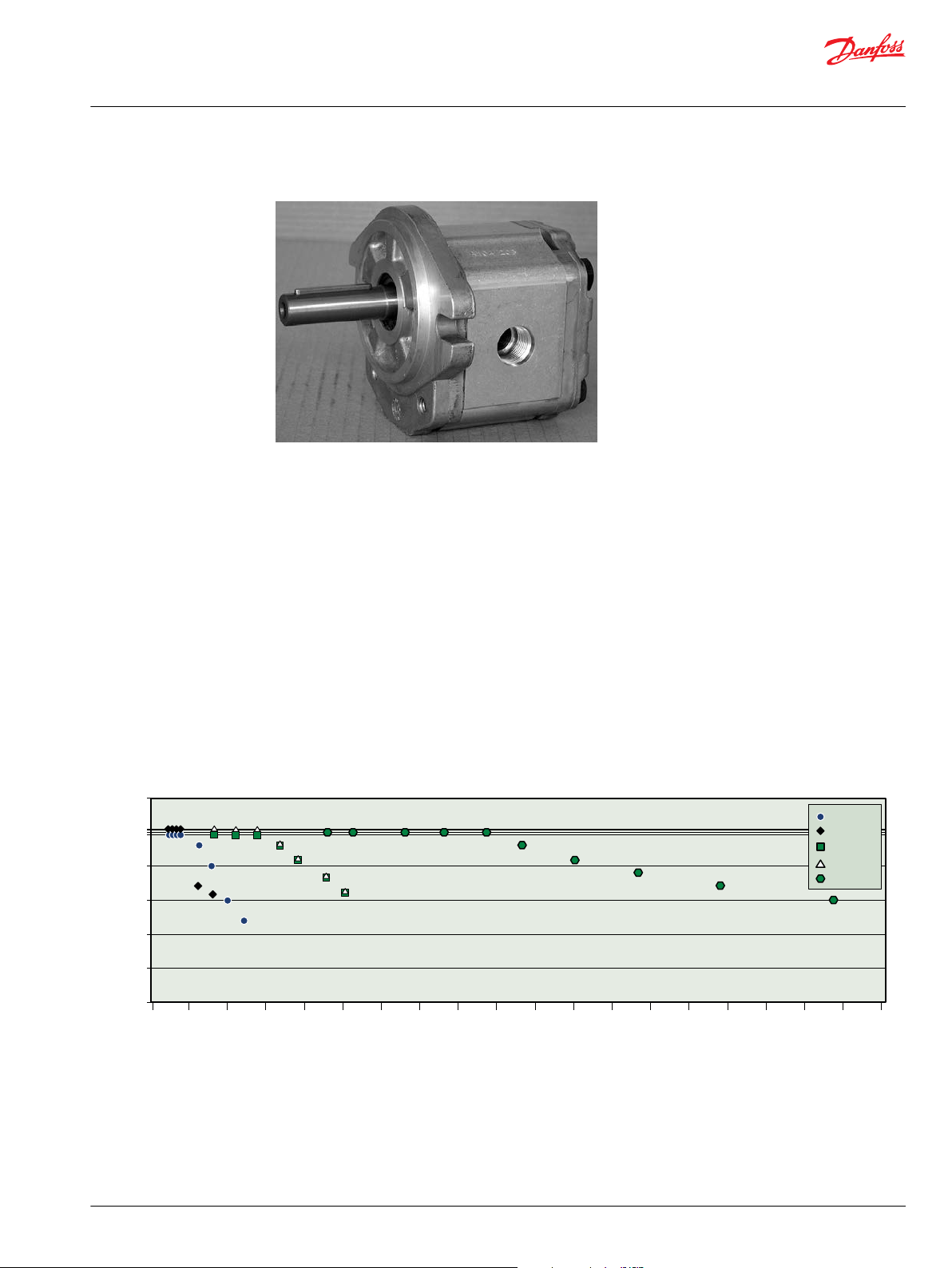
SNU2NN 06GB
Features and benefits
•
•
•
•
•
•
•
•
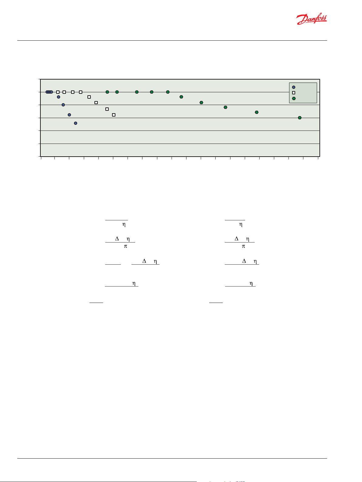
Three groups of frame sizes (Group 1, 2 and 3)
Displacements from 2.6 to 90 cm3/rev [from 0.158 to 5.49 in3/rev]
Available in uni- and bidirectional version for all the frame sizes, displacements and configurations
Rated pressure up to 250 bar [3625 psi]
Back pressure capability up to 250 bar [3625 psi]
Speeds up to 4000 min-1 (rpm) for Group 1 and 2, and up to 2500 min-1 (rpm) for Group 3
SAE, ISO and DIN mounting flanges and shafts
Available with integrated relief valve in the Group 2 frame size and integrated anti-cavitation valve in
Group 2 and Group 3 frame sizes
Motor displacements
Quick reference chart for unidirectional motor models (Group 1, 2 and 3)
©
Danfoss | July 2021 BC319483612502en-000102 | 7
Page 8
300
250
200
150
100
50
0
0 5 10 15 20 25 30 35 40 45 50 55 60 65 70 75 80 85 90 95
Displacement cm3/rev
SKM1NN
SNM2NN
SNM3NN
Rated pressure bar
Vg • n
1000 •
v
Qe =
Vg • p •
mh
20 •
Me =
Qe • p •
t
600
=
Me • n
9550
Pe=
n =
Qe • 1000 •
v
V
g
Vg • n
231 •
v
Qe =
Vg • p •
mh
2 •
Me =
Vg • n • p •
t
396 000
Pe=
n =
Qe • 231 •
v
V
g
Technical Information
G
ear Motors Group 1, 2, and 3
General information
Quick reference chart for bidirectional motor models (Group 1, 2 and 3)
Determination of nominal motor size
Based on SI units Based on US units
Where:
Q
Input flow (l/min)
e
M
Output torque (N•m)
e
P
Output power (kW)
e
n Speed (min-1)
V
Motor displacement per rev. (cm3/rev)
g
p
High pressure (bar)
high
p
Low pressure (bar)
low
∆p High pressure minus Low pressure (bar)
η
Motor volumetric efficiency
v
η
Mechanical-hydraulic efficiency
mh
η
Motor total efficiency (ηv • ηmh)
t
Where:
Q
Input flow [US gal/min]
e
M
Output torque [lb•in]
e
P
Output power [hp]
e
n Speed [rpm]
V
Motor displacement per rev. [in3/rev]
g
p
High pressure [psi]
high
p
Low pressure [psi]
low
∆p High pressure minus Low pressure [psi]
η
Motor volumetric efficiency
v
η
Mechanical-hydraulic efficiency
mh
η
Motor total efficiency (ηv • ηmh)
t
8 | © Danfoss | July 2021 BC319483612502en-000102
Page 9
Peak pressure
Rated pressure
Reaction time (100 ms max)
Time
Pressure
Technical Information
G
ear Motors Group 1, 2, and 3
System Requirements
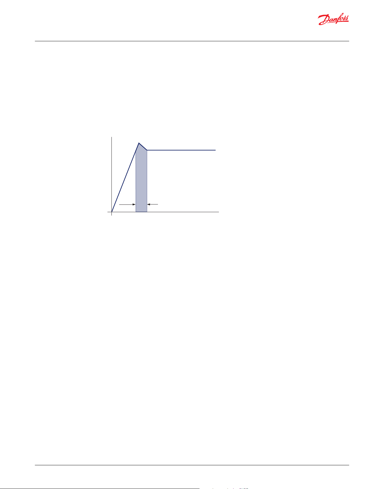
Pressure
Peak pressure is the highest intermittent pressure allowed.
The relief valve overshoot (reaction time) determines peak pressure. It is assumed to occur for less than
100 ms.
The illustration to the right shows peak pressure in relation to rated pressure and reaction time (100 ms
maximum).
Rated pressure is the average, regularly occurring operating inlet pressure that should yield satisfactory
product life. The maximum machine load at the motor shaft determines rated pressure
Speed
System pressure is the differential between the inlet and outlet ports. It is a dominant operating variable
affecting hydraulic unit life. High system pressure, resulting from high load at the motor shaft, reduces
expected life. System pressure must remain at, or below, rated pressure during normal operation to
achieve expected life.
Back pressure is the average, regularly occurring operating outlet pressure that should yield satisfactory
bidirectional motor life. The hydraulic load demand downstream of the motor determines the back
pressure. Unidirectional motors cannot work with back pressure and the maximum back pressure
allowed is 5 bar [72 psi] rated and 7 bar [101 psi ] as peak.
Case Drain Pressure is the regularly occurring case drain line pressure that should yield satisfactory
bidirectional motor life. It is recommended to design the case drain piping connecting the case drain
direct to the tank in order to keep the case drain pressure as low as possible. The max. continuous case
drain pressure allowed is 5 bar [72 psi] rated and 7 bar [101 psi] as peak.
Maximum speed is the limit recommended by Danfoss for a particular gear motor when operating at
rated pressure. It is the highest speed at which normal life can be expected.
The lower limit of operating speed is the minimum speed. It is the lowest speed at which normal life can
be expected.
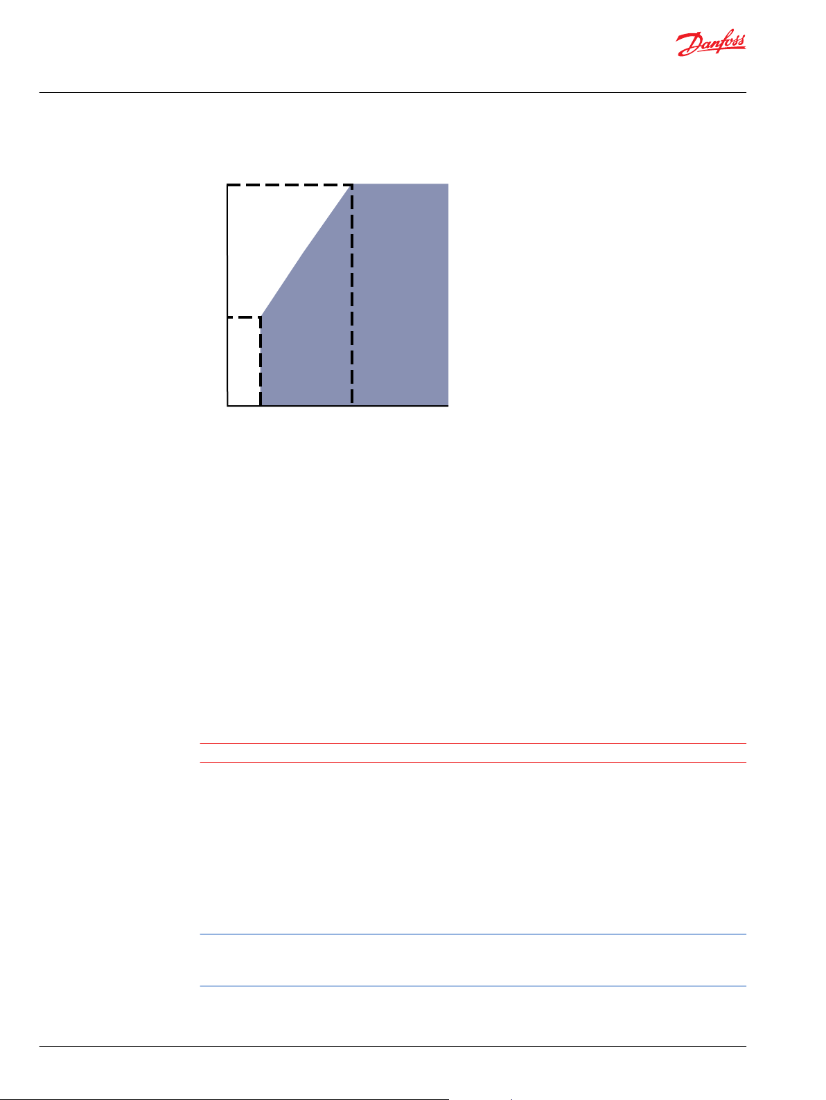
The minimum speed increases as operating system pressure increases. When operating under higher
pressures, a higher minimum speed must be maintained, as illustrated below.
©
Danfoss | July 2021 BC319483612502en-000102 | 9
Page 10
Rated
P
1
Pressure
0
N MaxN
2
Speed
Operating
envelope
1
C
Technical Information
G
ear Motors Group 1, 2, and 3
System Requirements
Speed versus pressure
Where:
N1 = Minimum speed at 100 bar
N2 = Minimum speed at rated pressure
Hydraulic Fluids
Temperature and Viscosity
Ratings and data for gear motors are guaranteed when the hydraulic system operates with premium
hydraulic fluids without containing oxidation, rust, or foam inhibitors.
These fluids have to work with good thermal and hydrolytic stability to prevent wear, erosion, or
corrosion of internal components. They include:
•
Hydraulic fluids following DIN 51524, part 2 (HLP) and part 3 (HVLP) specifications
•
API CD engine oils conforming to SAE J183
•
M2C33F or G automatic transmission fluids
•
Certain agricultural tractor fluids
Caution
Use only clean fluid in the gear motors and hydraulic circuit. Never mix hydraulic fluids.
Temperature and viscosity requirements must be concurrently met. Use of petroleum/mineral-based
fluids is highly recommended.
High temperature limits apply at the inlet port of the motors. The motors should operate at or below the
maximum continuous temperature. The peak temperature is based on material properties.
Don’t exceed it.
Minimum (cold start) temperature relates to the physical properties of component materials.
Cold oil, generally, doesn’t affect the durability of motors components. It may affect the ability of oil to
10 | © Danfoss | July 2021 BC319483612502en-000102
flow and transmit power. For this reason, keep the temperature at 16°C [60 °F] above the pour point of
the hydraulic fluid.
Page 11
Technical Information
G
ear Motors Group 1, 2, and 3
System Requirements
Temperature limits (with standard NBR seals)
Minimum viscosity occurs only during brief occasions of maximum ambient temperature and severe
duty cycle operation.
Maximum viscosity occurs at cold start only. During this condition, limit speeds until the system warms
up.
•
•
•
Fluid viscosity limits, in mm2/s [SUS]
Minimum (cold start) Maximum continuous Peak (intermittent)
-20°C [-4°F] 80°C [176°F] 90°C [194°F]
Size heat exchangers to keep the fluid within these limits
Test regularly to verify that these temperatures and viscosity limits aren’t exceeded
Keep the fluid viscosity in the recommended viscosity range for maximum unit efficiency and bearing
life
Maximum (cold start) Recommended range Range for high efficiency Minimum
1600 [7273] 12-100 [66-456] 20-50 [97-231] 10 [60]
Filtration
Filters
Use a filter that conforms to Class 22/18/13 of ISO 4406 (or better). It may be on the motor outlet
(discharge filtration) or inlet (pressure filtration).
Selecting a filter
When selecting a filter, please consider:
•
Contaminant ingression rate (determined by factors such as the number of actuators used in the
system)
•
Generation of contaminants in the system
•
Required fluid cleanliness
•
Desired maintenance interval
•
Filtration requirements of other system components
Measure filter efficiency with a Beta ratio (βX). βx ratio is a measure of filter efficiency defined by ISO 4572.
It is the ratio of the number of particles greater than a given diameter (in microns) upstream of the filter
to the number of these particles downstream of the filter.
•
For discharge filtration with controlled reservoir ingression, use a β
•
For pressure filtration, use a filtration with an efficiency of β10 = 75
The filtration requirements for each system are unique. Evaluate filtration system capacity by monitoring
and testing prototypes.
Fluid cleanliness level and βX ratio
Fluid cleanliness level (per ISO 4406)
βX ratio (discharge filtration)
βX ratio (pressure or return filtration)
Recommended inlet screen size
Class 22/18/13 or better
β
= 75 and β10 = 2
35-45
β10 = 75
100 – 125 μm [0.004 – 0.005 in]
35-45
= 75 filter
Reservoir
The reservoir provides clean fluid, dissipates heat, removes entrained air, and allows fluid volume
changes associated with fluid expansion and cylinder differential volumes. A correctly sized reservoir
©
Danfoss | July 2021 BC319483612502en-000102 | 11
Page 12

Pilot cavity
Ø 0.1 [0.004]
Mating spline
Technical Information
G
ear Motors Group 1, 2, and 3
System Requirements
accommodates maximum volume changes during all system operating modes. It promotes de-aeration
of the fluid as it passes through, and accommodates a fluid dwell-time between 60 and 180 seconds,
allowing entrained air to escape.
Minimum reservoir capacity depends on the volume required to cool and hold the oil from all retracted
cylinders, allowing for expansion due to temperature changes. A fluid volume of 1 to 3 times the pump
output flow (per minute) is satisfactory. The minimum reservoir capacity is 125% of the fluid volume.
Install the suction line above the bottom of the reservoir to take advantage of gravity separation and
prevent large foreign particles from entering the line. Cover the line with a 100-125 micron screen. The
pump should be below the lowest expected fluid level.
Put the return-line below the lowest expected fluid level to allow discharge into the reservoir for
maximum dwell and efficient deaeration. A baffle (or baffles) between the return and suction lines
promotes deaeration and reduces fluid surges.
Line sizing-x
Choose pipe sizes that accommodate minimum fluid velocity to reduce system noise, pressure drops, and
overheating. This maximizes system life and performance.
Design inlet piping that maintains continuous pump inlet pressure above 0.8 bar absolute during normal
operation. The line velocity should not exceed the values in the table below:
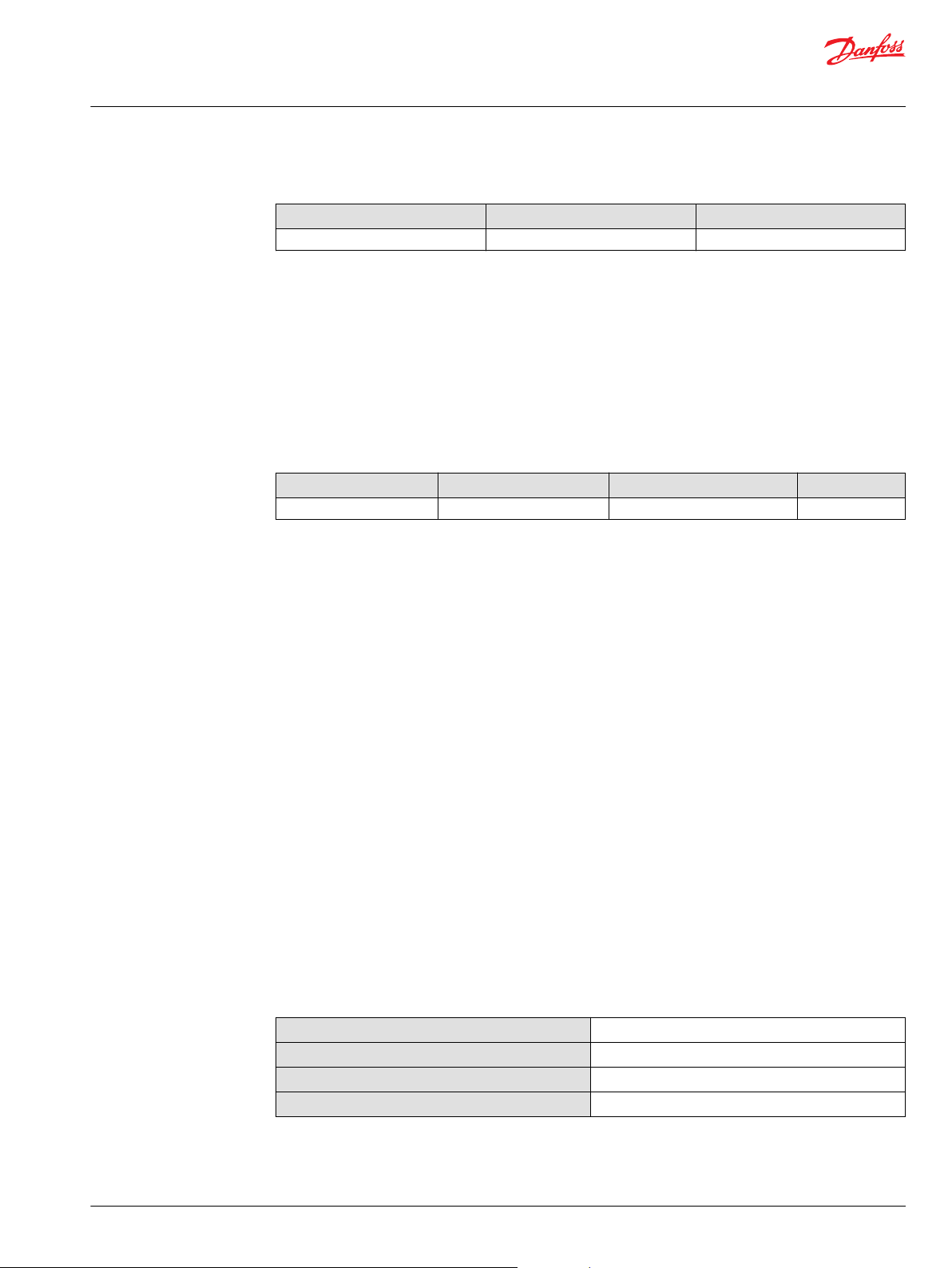
Motor shaft connection
Maximum line speed
Inlet Outlet Return
5 m/s [16.4 ft/sec] 2.5 m/s [8.2 ft/sec] 3 m/s [9.8 ft/sec]
Most systems use hydraulic oil containing 10% dissolved air by volume.
Over-aeration, or entrained air is the result of flow line restrictions, where the dissolved air comes out
of solutions, or when air is allowed to leak into the hydraulic circuit. These include inadequate pipes size,
sharp bends, or elbow fittings causing a reduction of flow-line cross-sectional area. This problem will not
occur if these circuit recommendations are followed, rated speed requirements are maintained, and
reservoir size and location are adequate.
Shaft options for gear motors include tapered, splined, and parallel shafts.
Plug-in drives, with a splined shaft, can impose severe radial loads when the mating spline is rigidly
supported. Increasing spline clearance does not alleviate this condition.
Use plug-in drives only if the concentricity between the mating spline and pilot diameter is within 0.1
mm [0.004 in]. Lubricate the drive by flooding with oil. A three-piece coupling minimizes radial or thrust
shaft loads.
Motor shaft connection
12 | © Danfoss | July 2021 BC319483612502en-000102
Page 13
a
90
o
α
0
o
270
o
180
o
Inlet port
Axial load
(A
L
)
Radial load (RL)
RL
Technical Information
G
ear Motors Group 1, 2, and 3
System Requirements
To avoid spline shaft damage, use carburized and hardened steel couplings with 80-82 HRA surface
hardness.
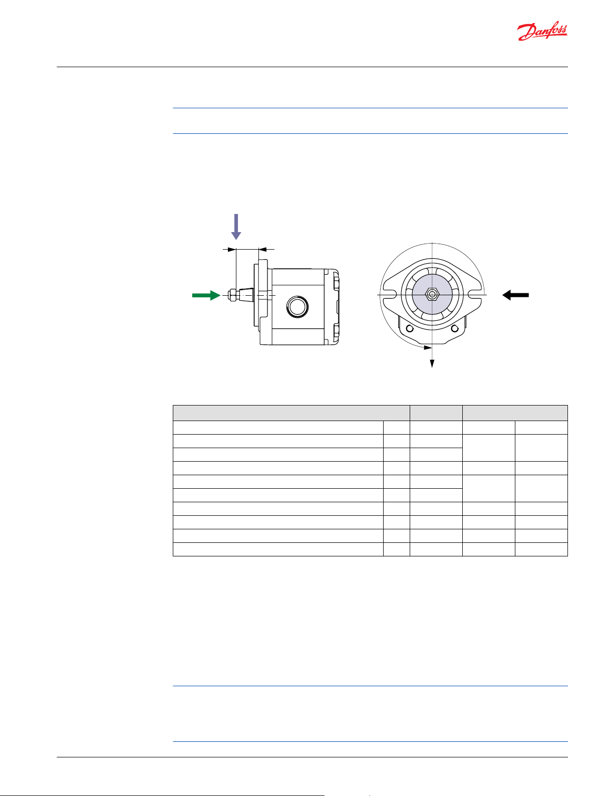
Motor shaft load data form
Photocopy this page and fax the complete form to your Danfoss representative for an assistance. This
illustration shows a motor with counterclockwise orientation:
Motor Life
Application data
Item Value Based on SI or US units
Motor displacement □ cm3/rev □ in3/rev
Rated system pressure □ bar □ psi
Peak pressure
Motor shaft rotation □ left □ right
Motor minimum speed
Motor maximum speed
Radial load R
Angular orientation of radial load to inlet port α degree
Axial load A
Distance from flange to radial load a □ mm □ in
1
1
min-1 (rpm)
□ N □ lbf
□ N □ lbf
Motor life is a function of speed, system pressure, and other system parameters (such as fluid quality and
cleanliness).
All Danfoss gear motors use hydrodynamic journal bearings that have an oil film maintained between the
gear/shaft and bearing surfaces at all times. If the oil film is sufficiently sustained through proper system
maintenance and operating within recommended limits, long life can be expected.
High pressure impacts motor life. When submitting an application for review, provide machine duty cycle
data that includes percentages of time at various loads and speeds.
B10 life expectancy number is generally associated with rolling element bearings. It does not exist for
hydrodynamic bearings.
Danfoss strongly recommends a prototype testing program to verify operating parameters and their
impact on life expectancy before finalizing any system design.
©
Danfoss | July 2021 BC319483612502en-000102 | 13
Page 14
Technical Information
G
ear Motors Group 1, 2, and 3
Group 1 Gear motors
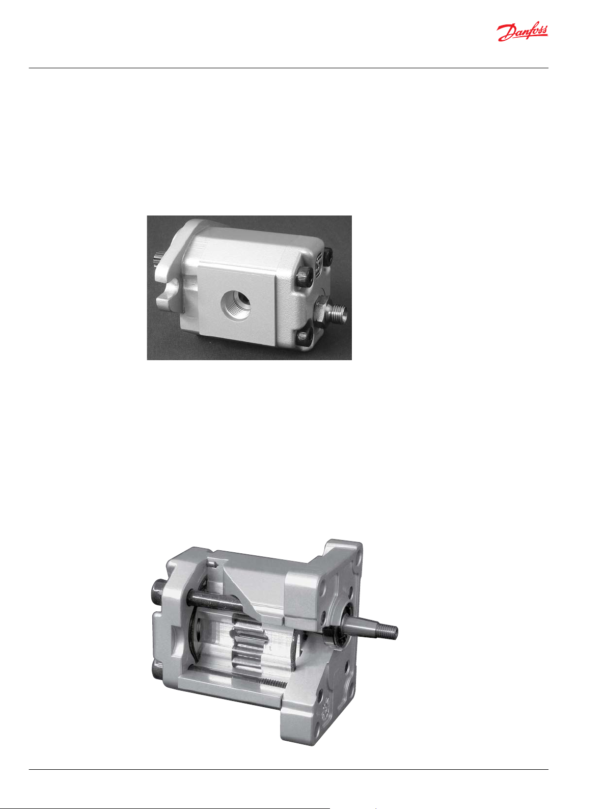
Motor design
SKM1NN
SKM1NN is the Group 1 bidirectional motor available in the whole displacements range from 2.6 up to 12
cm3/rev [from 0.158 up to 0.732 in3/ rev].
Configurations include European and SAE flanges and shafts (Code 01BA, 02BB, 02FA, 06GA, 06SA).
SKM1NN 06SA
SKU1NN
SKU1NN is a Group 1 unidirectional motor available in the whole displacements range from 2.6 up to 12
cm3/rev [from 0.158 up to 0.732 in3/rev]. The SKU1NN motor construction is derived from the
correspondent pump SKP1NN.
Configurations include European and SAE flanges and shafts (Code 01BA, 02BB, 02FA, 06GA, 06SA).
SNU1NN
SNU1NN is a Group 1 unidirectional motor available in a limited displacements range from 2.6 up to 7.8
cm3/rev [from 0.158 up to 0.464 in3/rev]. The SNU1NN motor construction is derived from the
correspondent pump SNP1NN. Configurations include European flange and shaft (Code 01BA).
SNU1NN 01BA (cut-away)
14 | © Danfoss | July 2021 BC319483612502en-000102
Page 15
C
Technical Information
G
ear Motors Group 1, 2, and 3
Group 1 Gear motors
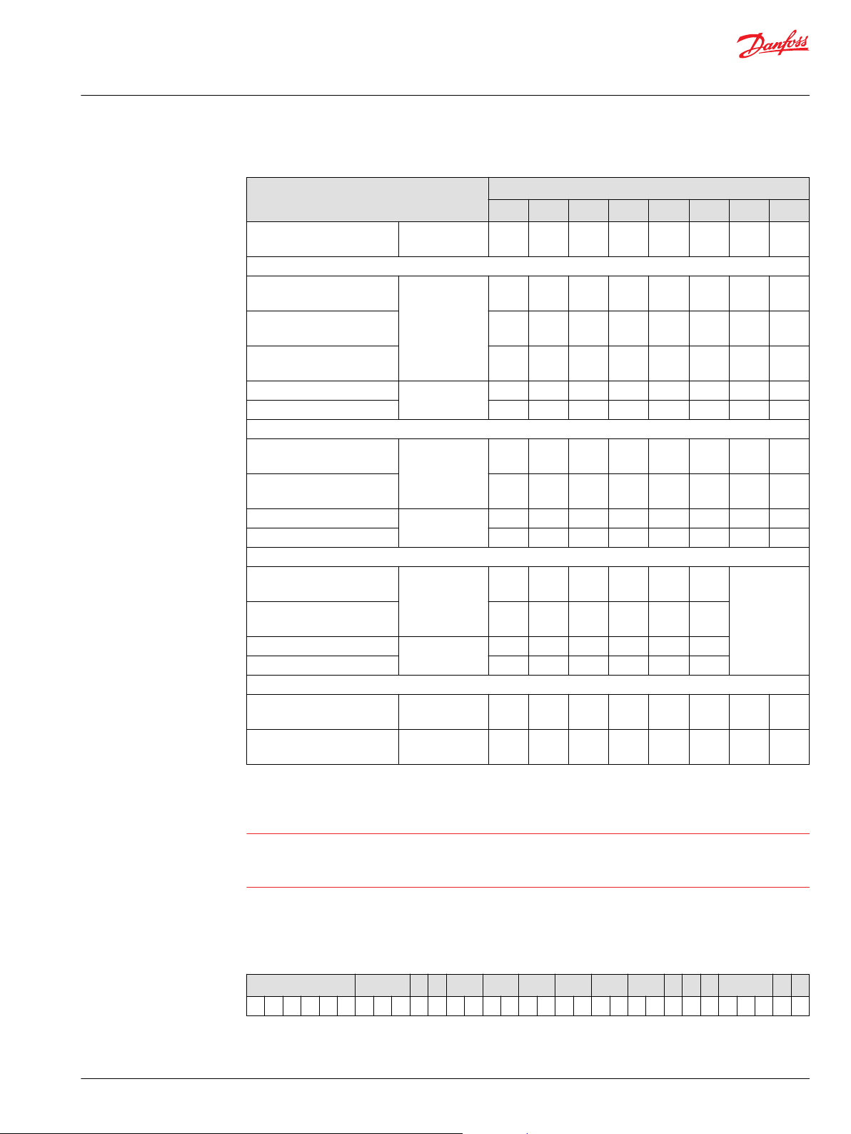
Technical data
Displacement cm3/rev [in3/rev]
SKM1NN (a standard, bidirectional motor)
Peak pressure
Rated pressure
Back pressure
Minimum speed min-1 (rpm) 1000 1000 1000 800 800 800 800 800
Maximum speed 4000 4000 3000 3000 2000 2000 2000 2000
SKU1NN (a standard, unidirectional motor)
Peak pressure
Rated pressure
Minimum speed min-1 (rpm) 1000 1000 1000 800 800 800 800 800
Maximum speed 4000 4000 3000 3000 2000 2000 2000 2000
SNU1NN (a standard, unidirectional motor)
Peak pressure
Rated pressure
Minimum speed min-1 (rpm) 1000 1000 1000 800 800 800
Maximum speed 4000 4000 3000 3000 2000 2000
All
Weight kg [lb]
Moment of inertia of rotating
components
Frame size
2,6 3,2 3,8 4,3 6,0 7,8 010 012
2.62
[0.158]
bar [psi] 270
[3915]
250
[3625]
250
[3625]
bar [psi] 270
[3915]
250
[3625]
bar [psi] 270
[3915]
250
[3625]
1.02
[2.26]
x 10-6 kg•m2
[x 10-6 lbf•ft2]
5.1
[121.0]
3.14
[0.195]
270
[3915]
250
[3625]
250
[3625]
270
[3915]
250
[3625]
270
[3915]
250
[3625]
1.14
[2.51]
5.7
[135.2]
3.66
[0.231]
270
[3915]
250
[3625]
250
[3625]
270
[3915]
250
[3625]
270
[3915]
250
[3625]
1.18
[2.60]
6.4
[151.9]
4.19
[0.262]
270
[3915]
250
[3625]
250
[3625]
270
[3915]
250
[3625]
270
[3915]
250
[3625]
1.20
[2.65]
7.1
[168.5]
5.89
[0.366]
250
[3625]
230
[3335]
230
[3335]
250
[3625]
230
[3335]
190
[2755]
170
[2465]
1.30
[2.87]
9.3
[220.7]
7.59
[0.463]
220
[3190]
200
[2900]
200
[2900]
220
[3190]
200
[2900]
180
[2610]
160
[2320]
1.39
[3.06]
11.4
[270.5]
9.94
[0.607]12[0.732]
180
150
[2610]
[2175]
160
130
[2320]
[1895]
160
130
[2320]
[1895]
170
140
[2465]
[2030]
150
120
[2175]
[1740]
–
1.55
1.65
[3.42]
[3.64]
14.6
17.1
[339.4]
[405.8]
1 kg•m2 = 23.68 lb•ft
2
Caution
The rated and peak pressure mentioned are for motors with flanged ports only. When threaded ports are
required a derated performance has to be considered. To verify the compliance of an high pressure
application with a threaded ports pump apply to a Danfoss representative.
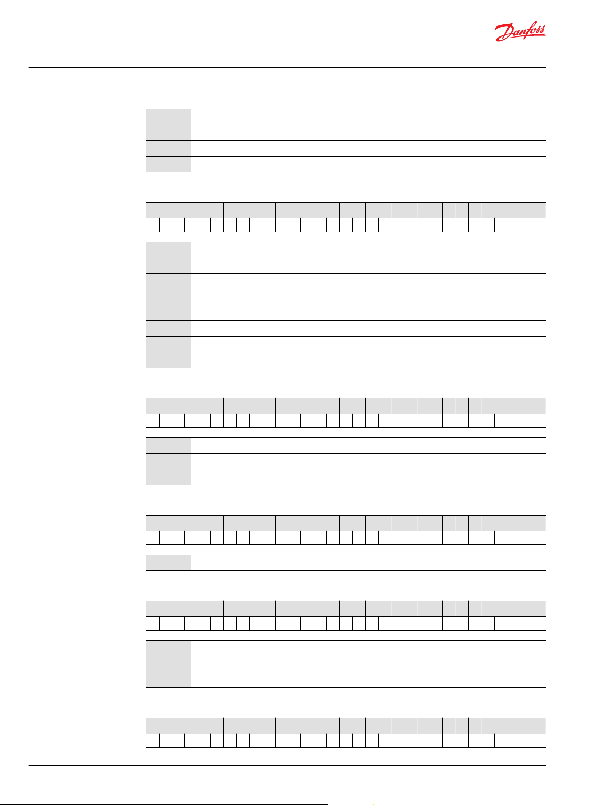
Model code
A Family
A B C D E F G H I J K L M N O
● ● ● ● ● ● /
©
Danfoss | July 2021 BC319483612502en-000102 | 15
Page 16
Technical Information
G
ear Motors Group 1, 2, and 3
Group 1 Gear motors
SNU1NN
SKU1NN
SKM1NN
SKM1IN
Unidirectional gear motor
High torque unidirectional gear motor
Bidirectional gear motor
Bidirectional gear motor with relief valve
B Displacement
A B C D E F G H I J K L M N O
2,6
3,2
3,8
4,3
6,0
7,8
010
012
2.62 cc
3.14 cc
3.66 cc
4.19 cc
5.89 cc
7.59 cc
9.94 cc
12.0 cc
C Rotation
A B C D E F G H I J K L M N O
● ● ● /
● /
L
R
B
Left (Counterclockwise)
Right (Clockwise)
Bidirectional
D Project version
A B C D E F G H I J K L M N O
N
Std Version of Project
E Mounting flange
A B C D E F G H I J K L M N O
01
02
06
European 4 bolt flange with pilot Ø25,4 mm
European 4 bolt flange with pilot Ø30 mm
SAE A-A 2 bolt flange with pilot Ø50,8 mm
F Drive Gear
A B C D E F G H I J K L M N O
● /
● ● /
● ● /
16 | © Danfoss | July 2021 BC319483612502en-000102
Page 17
Technical Information
G
ear Motors Group 1, 2, and 3
Group 1 Gear motors
BA
BB
FA
GA
SA
G Rear cover
A B C D E F G H I J K L M N O
P1
M1
M2
M3
M6
MH
I1
L6
V1
Taper 1:8-M7-Key2,41 SKP1
Taper 1:8-M10x1-Key 3
Parallel Ø12-Thread M10x1-Key 3
Parallel Ø12,7-Key 3,2
SAE spline J498-9T-20/40 Flat Root Side FIT-L15
● ● /
Standard cover for unidirectional motors
Standard cover for motors drain M12x1,5
Cover with drain 1/8" Gas
Cover with drain 1/4" Gas
Cover with drain 7/16-20UNF-2B
Cover with drain M12x1,5 ISO6149
Cover for unidirectional motors with relief valve
Cover motor with side drain in vertical axis 7/16-20UNF-2B
Cover for bidirectional motors with relief valve with drain 1/4 Gas
H Inlet size; I Outlet size
A B C D E F G H I J K L M N O
B2
C1
C2
C3
D3
D5
D7
13x30xM6
8x26xM5
12x26xM5
13,5x30xM6
M14x1,5
M18x1,5
M22x1,5
● ● ● ● /
©
Danfoss | July 2021 BC319483612502en-000102 | 17
Page 18
Technical Information
G
ear Motors Group 1, 2, and 3
Group 1 Gear motors
E3
E4
E5
F2
F3
F4
H2
H4
H5
H7
9/16-18UNF
3/4-16UNF
7/8-14UNF
1/4 GAS
3/8 GAS
1/2 GAS
10xM12x1,5-ISO6149
12xM16x1,5-ISO6149
12xM18x1,5-ISO6149
13,5xM22x1, 5-ISO6149
J Ports Pos & Spec Body
A B C D E F G H I J K L M N O
● ● /
N
Std from catalog
K Seals
A B C D E F G H I J K L M N O
N
H
Standard NBR seal
VITONseals + special backing ring - special for SKU1NN
L Screws
A B C D E F G H I J K L M N O
N
B
Std screws
GEOMET screws - Anticorrosion screws
M Set valves
A B C D E F G H I J K L M N O
NNN
*
V
*
For details, see Variant codes for ordering intergral relief valve on page 24.
No valve
Integralrelief valve pressure setting
● /
● /
/ ● ● ●
18 | © Danfoss | July 2021 BC319483612502en-000102
Page 19
Technical Information
G
ear Motors Group 1, 2, and 3
Group 1 Gear motors
N Type of mark
A B C D E F G H I J K L M N O
/ ●
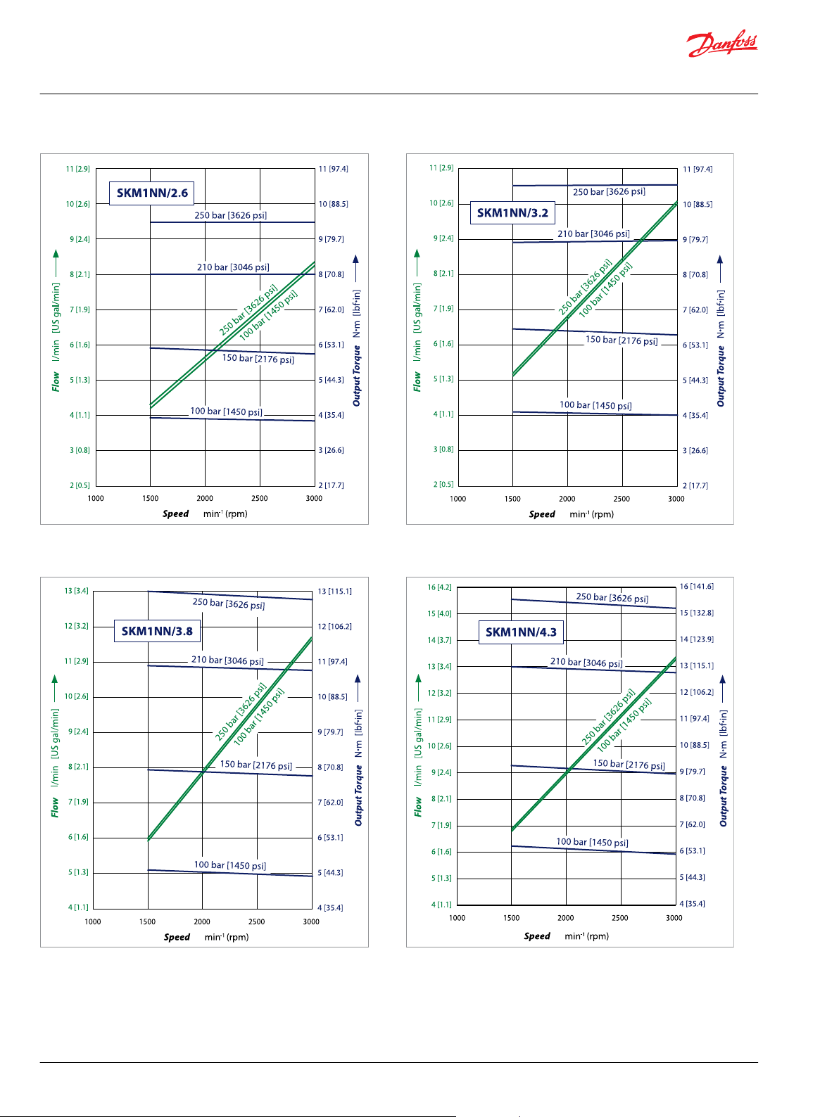
Motor performance graphs
N
A
Z
Standard Danfoss Marking
Standard Danfoss Marking+Customer Code-Special
Without Marking
O Mark position
A B C D E F G H I J K L M N O
/ ●
N
A
Std Marking position (on top)
Special Marking position on the bottom
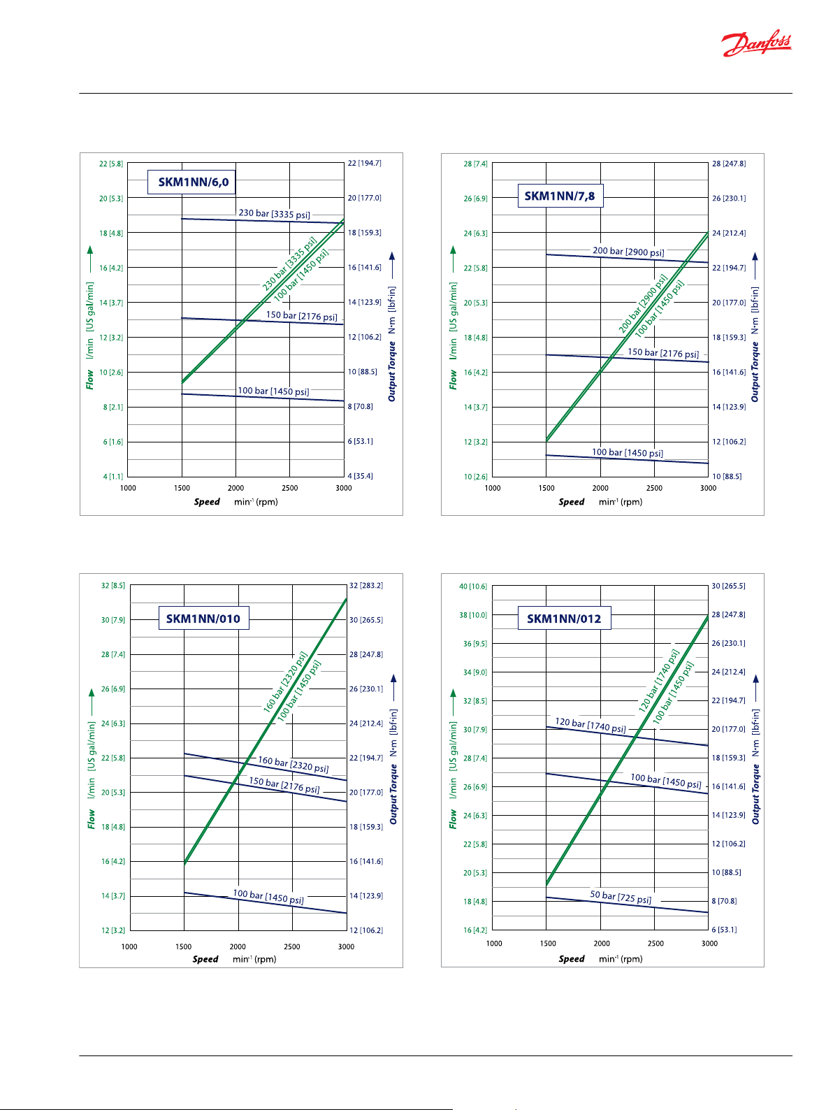
The following graphs provide typical inlet flow and output torque for Group 1 motors at various working
pressures. Data were taken using ISO VG46 petroleum /mineral based fluid at 50 °C [122 °F] (viscosity = 28
mm2/s [132 SUS]).
©
Danfoss | July 2021 BC319483612502en-000102 | 19
Page 20
Technical Information
G
ear Motors Group 1, 2, and 3
Group 1 Gear motors
20 | © Danfoss | July 2021 BC319483612502en-000102
Page 21
Technical Information
G
ear Motors Group 1, 2, and 3
Group 1 Gear motors
©
Danfoss | July 2021 BC319483612502en-000102 | 21
Page 22
Technical Information
G
ear Motors Group 1, 2, and 3
Group 1 Gear motors
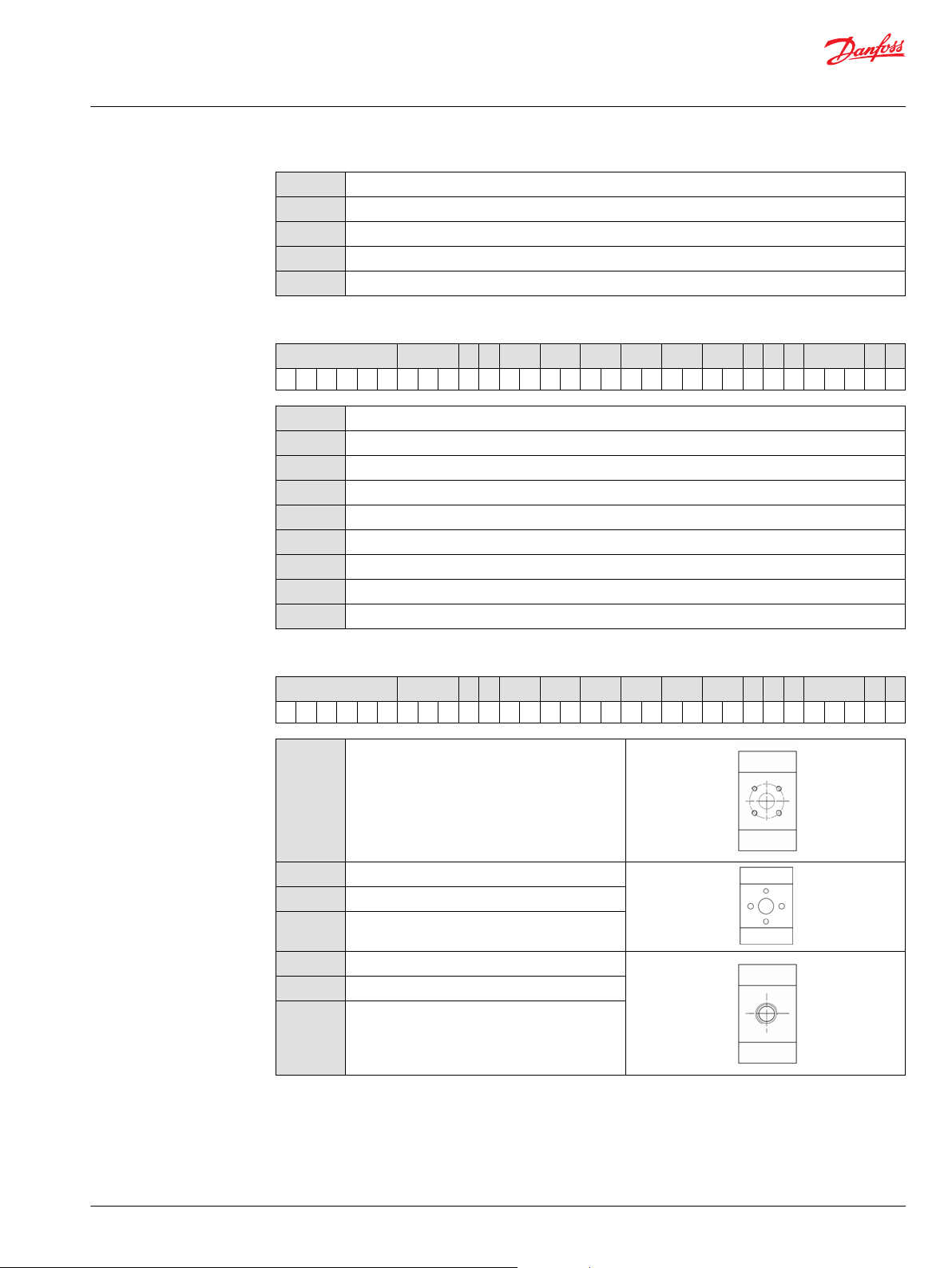
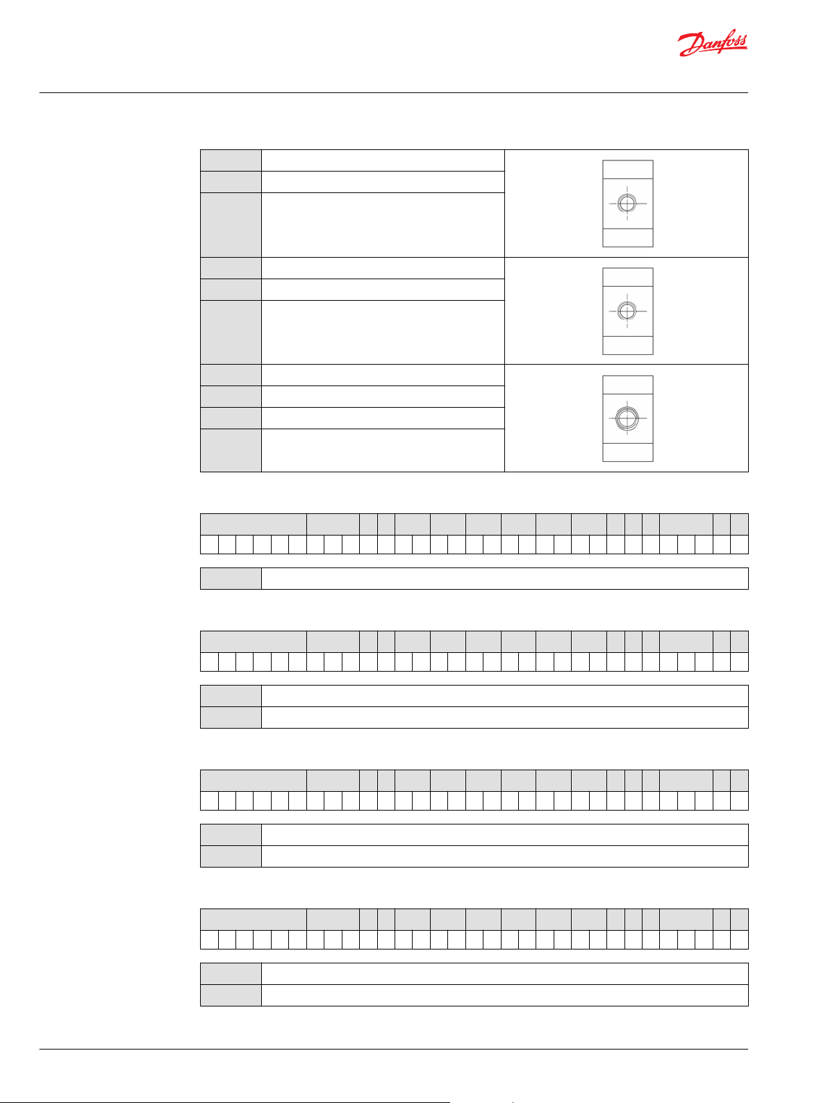
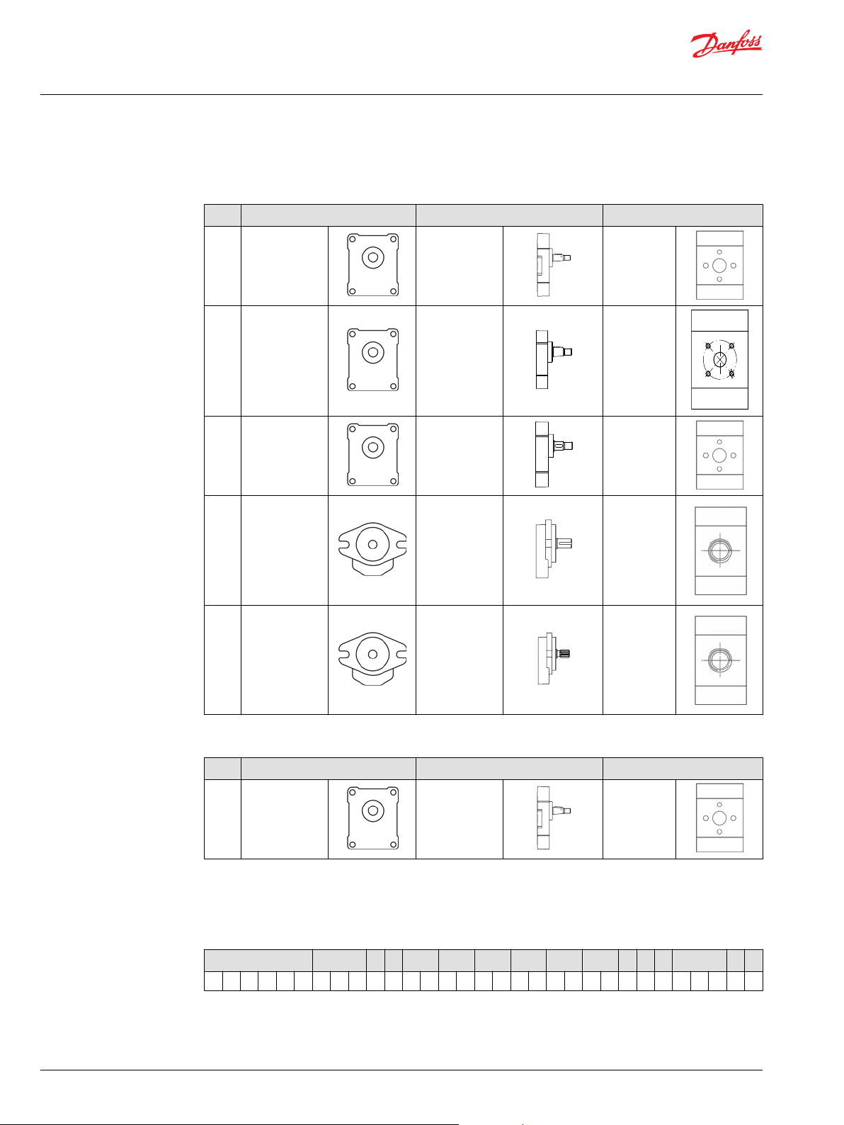
Flange, shaft and port configurations
...For SKM1NN and SKU1NN
Code Flange Shaft Port
01BA European 01, 4-
bolts pilot Ø
25.4 mm [1.0 in]
Taper 1:8
European in
+ pattern
02BB European 02, 4-
bolts pilot Ø 30
mm [1.181]
02FA European 02, 4-
bolts pilot Ø 30
mm [1.181]
06GA
SAE A-A 2-bolts Parallel
06SA SAE A-A 2-bolts
Taper 1:8 German
Parallel
12 mm [0.472 in]
12.7 mm [0.5 in]
SAE A-A
9-teeth splined
standard in X
pattern
European in
+ pattern
Threaded
SAE O-ring
boss
Threaded
SAE O-ring
boss
...For SNU1NN
Code Flange Shaft Port
01BA
European 01, 4bolts pilot Ø
25.4 mm [1.0 in]
Taper 1:8
European in
+ pattern
Shaft options
Group 1 motors are available with a variety of splined, parallel, and tapered shaft ends. Not all shaft styles
are available with all flange styles.
A B C D E F G H I J K L M N O
● ● /
22 | © Danfoss | July 2021 BC319483612502en-000102
Page 23
C
Technical Information
G
ear Motors Group 1, 2, and 3
Group 1 Gear motors
Shaft Mounting flange code with maximum torque
Code Description 01 02 06
BA
BB
DB
FA
GA
SA
Recommended mating splines for Group 1 splined output shafts should be in accordance with SAE J498
or DIN 5482. Danfoss external SAE splines are flat root side fit with circular tooth thickness reduced by
0.127 mm [0.005 in] in respect to class 1 fit. The external DIN splines have an offset increased by 0.1 mm
[0.004 in]. These dimensions are modified in order to assure a clearance fit with the mating spline.
Other shaft options may exist. Contact your Danfoss representative for availability.
Taper 1:8 25 [221] - -
Taper 1:8 - 50 [442] -
Splined Z15-m0,75-alfa 30°-L14 - 35 [309] -
Parallel 12 mm [0.47 in] - 24 [212] -
Parallel 12.7 mm [0.50 in] - - 32 [283]
SAE spline J 498-9T-20/40DP - - 34 [301]
Caution
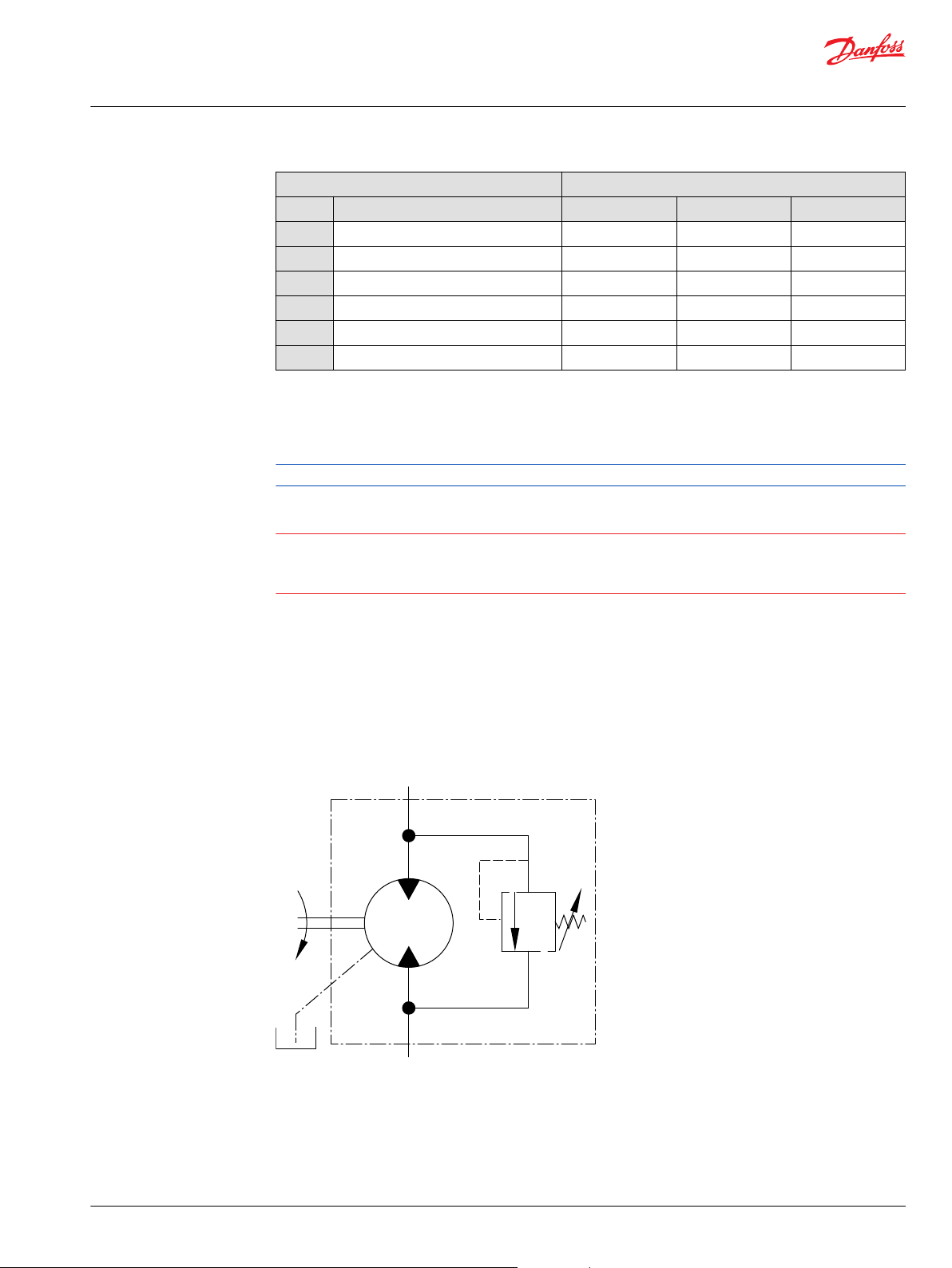
Integral relief value - SKM1IN
Shaft torque capability may limit allowable pressure. Torque ratings assume no external radial loading.
Applied torque must not exceed these limits, regardless of stated pressure parameters. Maximum torque
ratings are based on shaft torsional fatigue strength.
Danfoss offers an optional integral relief valve integrated in the Group 1 motors rear cover. It is drained
internally and directs all the flow from the motor inlet to the outlet when the inlet pressure reaches the
valve setting.
The tables below show applicable variant codes for ordering motors with integral relief valve. Refer to
Model code on page 15 for more information.
Valve schematic diagram
©
Danfoss | July 2021 BC319483612502en-000102 | 23
Page 24
Inlet
Drain
P101 016
bar
0
[1000]
[2000]
[3000]
[4000]
[5000]
[psi]
l/min
0
[US gal/min]
0
100
200
300
400
With mineral oil at 26 mm2/s
10 3020 40
[10][2] [4]
[6] [8]
MINIMUM VALVE SETTING
Technical Information
G
ear Motors Group 1, 2, and 3
Group 1 Gear motors
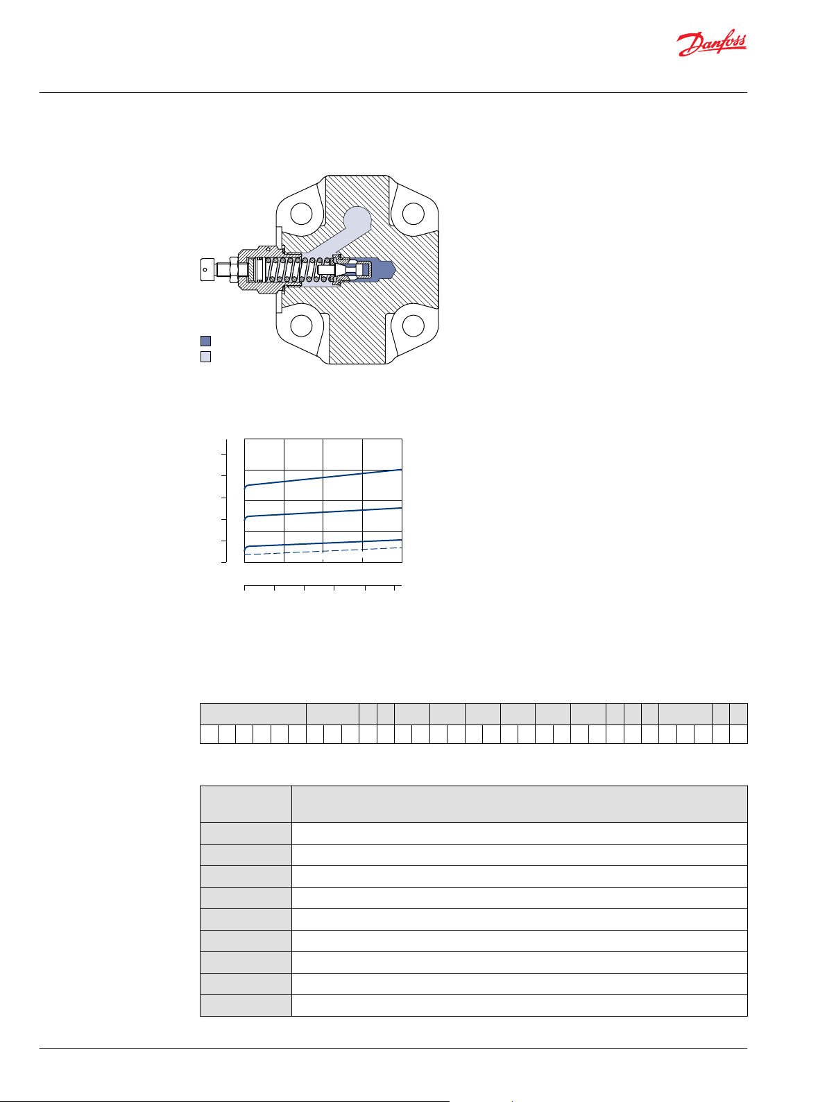
Integral relief valve rear cover cross section
Pressure vs flow
Variant codes for ordering intergral relief valve
Variant codes for ordering integral relief valve
A B C D E F G H I J K L M N O
/ V ● ●
M Variant code (left part)
Code
A
C
E
F
G
K
I
L
M
24 | © Danfoss | July 2021 BC319483612502en-000102
Motor speed for RV setting
min-1 (rpm)
not defined
500
1000
1250
1500
2000
2250
2500
2800
Page 25
Technical Information
G
ear Motors Group 1, 2, and 3
Group 1 Gear motors
M Variant code (left part) (continued)
Code
N
O
M Variant code (right part)
Code
A
B
C
D
E
F
G
J
K
L
M
N
O
P
Q
R
S
T
U
V
W
X
Z
Motor speed for RV setting
min-1 (rpm)
3000
3250
Pressure setting bar
[psi]
no setting
no valve
18 [261]
25 [363]
30 [435]
35 [508]
40 [580]
150 [2175]
50 [725]
60 [870]
70 [1015]
80 [1160]
90 [1305]
100 [1450]
110 [1595]
120 [1740]
130 [1885]
140 [2030]
160 [2321]
170 [2466]
180 [2611]
210 [3046]
250 [3626]
©
Danfoss | July 2021 BC319483612502en-000102 | 25
Page 26

g
CB
h
x
y
45o
i (4 holes min. full thd.
20 mm [0.787 in] deep)
z (4 holes min. full thd.
20 mm [0.787 in] deep)
D
FE
d
f
e
Technical Information
G
ear Motors Group 1, 2, and 3
Group 1 Gear motors
Ports dimensions
Available ports for Group 1 motors
Bidirectional motor ports
SKM1NN bidirectional motor ports dimensions (all frame sizes)
Port type B C D E F
Port dimensions g h i x y z d e f
Inlet/Outlet
Drain
13
[0.512]30[1.181]
M12x1.5 M12x1.5 M12x1.57/16–20UNF–2B 1/8 Gas
M6
12
[0.472]26[1.024]
M5 M18x1.5¾–16UNF–2B 3/₈ Gas
(BSPP)
(BSPP)
26 | © Danfoss | July 2021 BC319483612502en-000102
Page 27

Technical Information
G
ear Motors Group 1, 2, and 3
Group 1 Gear motors
Unidirectional motor ports
SKU1NN, SNU1NN unidirectional motor ports dimensions (all frame sizes)
Port type B C D E F
Port dimensions g h i x y z d e f
2.6 Inlet
3.2 Inlet
3.8 Inlet
4.3 Inlet
6.0 Inlet
7.8 Inlet
010 Inlet
012 Inlet
Outlet
Outlet
Outlet
Outlet
Outlet
Outlet
Outlet
Outlet
8
[0.315]
13
[0.512]
8
[0.315]
13
[0.512]
8
[0.315]
13
[0.512]
8
[0.315]
13
[0.512]
13
[0.512]
13
[0.512]
13
[0.512]
13
[0.512]
13
[0.512]
13
[0.512]
13
[0.512]
13
[0.512]
30
[1.181]
M6
12
[0.472]26[1.024]
M14x1.59/₁₆–18UNF–
M18x1.5¾–16UNF–2B
M14x1.59/₁₆–18UNF–
M18x1.5¾–16UNF–2B
M14x1.59/₁₆–18UNF–
M18x1.5¾–16UNF–2B
M14x1.59/₁₆–18UNF–
M18x1.5¾–16UNF–2B
M5
M18x1.59/₁₆–18UNF–
M18x1.5¾–16UNF–2B
M18x1.59/₁₆–18UNF–
M18x1.5¾–16UNF–2B
M18x1.59/₁₆–18UNF–
M18x1.5¾–16UNF–2B
M18x1.59/₁₆–18UNF–
M18x1.5¾–16UNF–2B
2B
2B
2B
2B
3/8 Gas
(BSPP)
2B
2B
2B
2B
Dimensions
©
Danfoss | July 2021 BC319483612502en-000102 | 27
Page 28

01BA
1:8
Cone reference diameter
to cone reference diameter
Recommended
tightening
torque: 7-12 Nm
Distance from front flange
29 [1.14]
M7-6g
14.4 [0.583]
5.2 [0.205]
12.4 [0.488]
X
Pilot width
-0.041
-0.020
16.5 [0.65]
4.2 [0.165]
X
Ø
0.75
body width
69.4 [2.73] max
52.4 [2.06]
88.1 [3.47] max
74.5 [2.93] max
(53.8 max)
[2.12]
(34.3 max)
[1.35]
(71.9)
[2.83]
26.2
[1.03]
45.7
[1.8]
68 ±0.25 [2.68 ±0.010]
5.5 [0.217 ]
+0.15
-0.25
+0.0059
-0.0098
-0.0098
2.41 [0.0949 ]
0
-0.025
0
D/d
E/e
C/c
(min full thd 10 [0.394] deep)
±0.50 [0.020]
±0.20 [0.008]
B
max
A
A
A
A-A
Ø 25.4 [1.0 ]
Ø 9.82 [0.387]
10.8 ±0.50 [0.425 ±0.020]
Ø7.2 - 8
[.283- .315]
-0.0016
-0.0008
21.6 ±0.50
[0.85 ±0.020]
M12x1.5-6H
Drain port
Technical Information
G
ear Motors Group 1, 2, and 3
Group 1 Gear motors
SKM1NN, SKU1NN, SNU1NN – 01BA
Standard porting drawing for 01BA
For unidirectional motors no case drain hole into the rear cover.
SKM1NN – 01BA dimensions
Type (displacement) 2.6 3.2 3.8 4.3 6.0 7.8 010 012
Dimension A 40.5
[1.594]
Inlet/Outlet C/c 12 [0.472]
For unidirectional SNU1NN, SKU1NN dimensions see Ports dimensions on page 26.
Model code examples and maximum shaft torque
B
85.0
[3.346]
D/d 26 [1.024]
E/e M5
Flange/drive gear Model code example Maximum shaft torque
01BA SKM1NN/3,2BN01BAM1C2C2NNNN/NNNNN
SKU1NN/4,3LN01BAP1C2C2NNNN/NNNNN
SNU1NN/3,8RN01BAP1F3F3NNNN/NNNNN
28 | © Danfoss | July 2021 BC319483612502en-000102
For further details on ordering, see Model code on page 15.
41.5
[1.634]
87.0
[3.425]
42.5
[1.673]
89.0
[3.504]
43.5
[1.713]
91.0
[3.583]
46.75
[1.841]
97.5
[3.839]
50.0
[1.969]
104.0
[4.094]
54.5
[2.146]
113.0
[4.449]
25 N•m [221 lb•in]
58.5
[2.303]
121.0
[4.764]
Page 29

12.0 [0.472 ]
+0.0 +0.0
-0.018 -0.001
M10 x 1-6g
11.7 [0.461]
8.3 [0.327]
Distance from front
flange to shoulder
31.5 [1.240]
3.0 [0.118 ]
+0.0 +0.0
-0.030 -0.001
13.2 [0.520 ]
+0.05 +0.002
-0.20 -0.008
88.2 [3.472] max
7.5 [0.295 ]
+0.25 +0.010
-0.15 -0.006
3.0 [0.118
]
0
0
-0.030 -0.001
C/c
D/d
E/e
A
A
A
A-A
16.5 [0.650]
7.0 [0.276]
Pilot width
8.0 [0.315]
Distance from front flange
to cone reference diameter
B max
M10x1-6g
Ø13.95 [0.549]
Cone re ference diameter
10.8 [0.425
30.0 [1.181 ]
-0.020 -0.0008
-0.041 -0.0016
68.0
[23.677 ]
body width
74.5 [2.933] max
56.0 [2.205]
70.9 [2.791] max
24.5 [0.965]
48.5 [1.909]
(73.0 [2.874])
(32.1 [1.264] max)
(56.1 [2.209] max)
Ø 6.7-7.5
[0.264-0.295]
1:
8
35 [1.378]
15.75 [0.620]
15.5 [0.610]
±0.25
±0.20 [±0.08]
±0.50 ±0.020]
±0.50 [±0.02]
±0.010
02BB 02FA
(min full thd 10 [0.394] deep)
X
Ø 0.75 [0.0295]
M12x1.5-6H
Drain port
B
B
B-B
X
Recommended
tightening
torque: 10-16 Nm
Recommended
tightening
torque: 10-16 Nm
Technical Information
G
ear Motors Group 1, 2, and 3
Group 1 Gear motors
SKM1NN, SKU1NN – 02BB, 02FA
Standard porting drawing for 02BB, 02FA
For unidirectional motors no case drain hole into the rear cover.
SKM1NN – 02BB and 02FA dimensions
Type (displacement) 2.6 3.2 3.8 4.3 6.0 7.8 010 012
Dimension A 40.5
[1.594]
B
85.0
[3.346]
Inlet/Outlet C/c 12 [0.472]
D/d 26 [1.024]
E/e M5
For unidirectional SKU1NN dimensions see Ports dimensions on page 26.
Model code examples and maximum shaft torque
Flange/drive gear Model code example Maximum shaft torque
02BB SKM1NN/010BN02BBM1C2C2NNNN/NNNNN
SKU1NN/6,0LN02BBM1C2C2NNNN/NNNNN
02FA
For further details on ordering, see Model code on page 15.
SKM1NN/6,0BN02FAM1C2C2NNNN/NNNNN
SKU1NN/6,0LN02FAM1C2C2NNNN/NNNNN
41.5
[1.634]
87.0
[3.425]
42.5
[1.673]
89.0
[3.504]
43.5
[1.713]
91.0
[3.583]
46.75
[1.841]
97.5
[3.839]
50.0
[1.969]
104.0
[4.094]
54.5
[2.146]
113.0
[4.449]
50 N•m [442 lb•in]
24 N•m [212 lb•in]
58.5
[2.303]
121.0
[4.764]
©
Danfoss | July 2021 BC319483612502en-000102 | 29
Page 30

12.344 [0.486 ]
0
0
0
0
-0.05
Splined:
SAE J498-9T-20/40DP
Flat root side fit
Circular tooth thickness:
0.127 [0.005]
less than class 1 fit
15.6 [0.614]
19.1 [0.752]
7.9 [0.311]
27.0 [1.063]
74.5 [2.933] max
body width
R 32.1 [1.26] max
82.55 [3.258]
103.4 [4.071] max
80.2 [3.157] max
X
10.2-10.8 [.402-.425]
Ø 0.75 [0.030]
3.2 [0.126 ]
-0.025 -0.126
13.94-14.20
[0.549-0.559]
Straight thread
O-Ring boss
8.0 [0.315]
6.0 [0.236]
Pilot width
7.9 [0.311]
Distance from front flange to shoulder
Distance from front
flange to shoulder
19.1
[0.752]
27.0 [1.063]
12.7 [0.500 ]
-0.025 -0.001
10.8 ±0.50 [0.425 ±0.020]
68.0 ±0.25 [2.677 ±0.010]
50.8 [2.0 ]
0
0
-0.050 -0.002
06GA
06SA
C/c
±0.50 [0.020]
B
max
A
A
A
A-A
-0.127
0
0
7/16-20UNF-2B
Drain port
X
Technical Information
G
ear Motors Group 1, 2, and 3
Group 1 Gear motors
SKM1NN, SKU1NN – 06GA and 06SA
Standard porting drawing for 06GA and 06SA
For unidirectional motors no case drain hole into the rear cover.
SKM1NN – 06GA and 06SA dimensions
Type (displacement) 2.6 3.2 3.8 4.3 6.0 7.8 010 012
Dimension A 45
[1.771]46[1.811]47[1.850]48[1.889]
B
89.5
[3.523]
91.5
[3.602]
93.5
[3.681]
95.5
[3.759]
51.25
[2.017]
102
[3.839]
54.5
[2.145]59[2.322]
108.5
[4.015]
117.5
[4.625]
63.5
[2.500]
125.5
[4.940]
Inlet/Outlet C/c ¾–16UNF–2B, THD 14.3 [0.563] deep
For unidirectional SKU1NN dimensions see Ports dimensions on page 26.
Model code examples and maximum shaft torque
Flange/drive gear Model code example Maximum shaft torque
06GA SKM1NN/6,0BN06GAM6E4E4NNNN/NNNNN
SKU1NN/4,3RN06GAP1E3E4NNNN/NNNNN
06SA
SKM1NN/012BN06SAM6E4E4NNNN/NNNNN
SKU1NN/3,2LN06SAP1E3E4NNNN/NNNNN
For further details on ordering, see Model code on page 15.
32 N•m [283 lb•in]
34 N•m [301 lb•in]
30 | © Danfoss | July 2021 BC319483612502en-000102
Page 31

Technical Information
G
ear Motors Group 1, 2, and 3
Group 2 Gear motors
Motor design
SNM2NN
SNM2NN is the group 2 bidirectional motor available in the whole displacements range from 6 up to 25
cm3/rev [from 0.37 up to 1.538 in3/rev].
Configurations include European and SAE flanges and shafts (Code 01BA, 01FA, 01DA, 02AA, 02DB, 03CA,
04AA/05AA, 04DB/05DB, 06GA, 06SA).
SNU2NN
SNU2NN is the group 2 unidirectional motor available in the displacements range from 8 up to 25
cm3/rev [from 0.513 up to 1.538 in3/rev]. The SNU2NN motor construction is derived from the
correspondent pump SNP2NN.
Configurations include European and SAE flanges and shafts (Code 01BA, 01FA, 01DA, SNU2NN 06SA (cut
away) 02AA, 02DB, 03CA, 04AA/05AA, 04DB/05DB, 06GA, 06SA).
©
Danfoss | July 2021 BC319483612502en-000102 | 31
Page 32

Technical Information
G
ear Motors Group 1, 2, and 3
Group 2 Gear motors
Technical data
SKU2NN
SKU2NN is the Group 2 unidirectional motor available in the displacements range from 8 up to 25
cm3/rev [from 0.513 up to 1.538 in3/rev]. The SKU2NN motor construction is derived from the
correspondent pump SKP2NN. Configuration includes SAE flange and shaft only (Code 06SA).
The table below details the technical data for Group 2 gear motors based on the model and displacement
configuration.
Technical data for Group 2 gear motors
Frame size
*
6.0
Displacement cm3/rev
SNM2NN (bidirectional motor)
Peak pressure
Rated pressure
Outlet back
pressure
[in3/rev]
bar [psi] 280
6.0
[0.36]
[4060]
250
[3625]
250
[3625]
8.0 011 014 017 019 022 025
8.4
[0.513]
280
[4060]
250
[3625]
250
[3625]
10.8
[0.659]
280
[4060]
250
[3625]
250
[3625]
14.4
[0.879]
280
[4060]
250
[3625]
250
[3625]
16.8
[1.025]
260
[3770]
230
[3335]
230
[3335]
19.2
[1.171]
230
[3335]
210
[3045]
210
[3045]
22.8
[1.391]
200
[2900]
180
[2610]
180
[2610]
25.2
[1.538]
180
[2610]
160
[2320]
160
[2320]
32 | © Danfoss | July 2021 BC319483612502en-000102
Page 33

C
Technical Information
G
ear Motors Group 1, 2, and 3
Group 2 Gear motors
Technical data for Group 2 gear motors (continued)
Minimum
speed
Maximum
speed
SNU2NN (unidirectional motor)
Peak pressure
Rated pressure
Minimum
speed
Maximum
speed
SKU2NN (unidirectional motor)
Peak pressure
Rated pressure
Minimum
speed
Maximum
speed
All (SNM2NN, SNU2NN, SKU2NN)
Weight kg [lb]
Moment of
inertia of
rotating
components
Theoretical
flow at
maximum
speed
*
Before chosing this frame size, please apply to Danfoss technical department.
Frame size
*
6.0
min-1(rpm)700 700 700 700 500 500 500 500
4000 4000 4000 4000 4000 3500 3500 3500
bar [psi] – 280
-1
min
(rpm)
bar [psi] – 280
-1
min
(rpm)
2.4
[5.3]
-6
x 10
kg•m
[x 10
lb•ft2]
l/min [US
gal/min]
26.5
2
[629]
-6
24
[6.3]
8.0 011 014 017 019 022 025
280
[4060]
250
[3625]
600 600 600 500 500 500 500
3500 3500 3500 3000 3000 3000 2500
[4060]
250
[3625]
600 600 600 500 500 500 500
3500 3500 3500 3000 3000 3000 2500
2.5
[5.5]
32.4
[769]
33.6
[8.9]
[4060]
250
[3625]
280
[4060]
250
[3625]
2.7
[5.5]
38.4
[911]
43.2
[11.4]
280
[4060]
250
[3625]
280
[4060]
250
[3625]
2.9
[6.3]
47.3
[1122]
50.4
[13.3]
260
[3770]
230
[3335]
260
[3770]
230
[3335]
3.0
[6.5]
53.3
[1265]
50.4
[13.3]
230
[3335]
210
[3045]
230
[3335]
210
[3045]
3.1
[6.7]
59.2
[1405]
57.6
[15.2]
200
[2900]
180
[2610]
200
[2900]
180
[2610]
3.2
[7.0]
68.1
[1616]
68.4
[18.0]
180
[2610]
160
[2320]
175
[2815]
160
[2320]
3.3
[7.3]
74.1
[1758]
75.6
[20.0]
1 kg•m2 = 23.68 lb•ft
2
Caution
The rated and peak pressure mentioned are for motors with flanged ports only. When threaded ports are
required a de-rated performance has to be considered. To verify the compliance of an high pressure
application with a threaded ports pump apply to a Danfoss representative.
Model code
A Family
A B C D E F G H I J K L M N O
● ● ● ● ● ● /
©
Danfoss | July 2021 BC319483612502en-000102 | 33
Page 34

Technical Information
G
ear Motors Group 1, 2, and 3
Group 2 Gear motors
SKU2NN
SNM2DN
SNM2GC
SNM2GL
SNM2GN
SNM2IL
SNM2IN
SNM2JN
SNM2NC
SNM2NL
SNM2NN
SNU2EN
SNU2GN
SNU2GC
SNU2IN
SNU2JN
SNU2NC
SNU2NN
SNU2QN
GR2 Unidir.Motor (only available in combination with SB shaft)
Gr2 Bidir.Motor-Int.Drain
Gr2 Bidir.Motor+In./Out. on CoverAnticav.Check Valve (axial drain)
Gr2 Bidir.Motor-Anticav.Check Val.-vert.drain
Gr2 Bidir.Motor-Anticav.Check Valve (axial drain)
Gr2 Bidir.Motor+Int.drain RV-Vert.drain
Gr2 Bidir.Motor+Int.drain RV
Gr2 Bid.Motor+Int.drain RV+Anticav.Check Valve
Gr2 Bidir.Motor-Cover Ports-Ax.drain
Gr2 Bidir.Motor-Vert.drain
Gr2 Bidir.Motor
Gr2 Unidir.Motor+Ext.drain RV
Gr2 Unidir.Motor+Anticav.Check Valve
Gr2 Unidir.Motor-In./Out. on Cover+Anticav.Check Valve
Gr2 Unidir.Motor+Int.drain RV
Gr2 Unidir.Motor+Int.drain RV+Anticav.Check Valve
Gr2 Unidir.Motor-In.-Out.on cover
Gr2 Unidir.Motor
Gr2 Unid.Motor-Ext.drain RV+Anticav.Check Valve
B Displacement
A B C D E F G H I J K L M N O
6,0
8,0
011
014
017
019
022
025
6,0 cc -Special
8,4 cc
10,8 cc
14,4 cc
16,8 cc
19,2 cc
22,8 cc
25,2 cc
C Rotation
A B C D E F G H I J K L M N O
L
R
B
Left (Counterclockwise)
Right (Clockwise)
Bidirectional
● ● ● /
● /
34 | © Danfoss | July 2021 BC319483612502en-000102
Page 35

Technical Information
G
ear Motors Group 1, 2, and 3
Group 2 Gear motors
D Project version
N Std Version of Project
4 Precharged seal on cover-Special
6 Short version - Special
E Mounting flange
A B C D E F G H I J K L M N O
● /
heavy-duty applications
A B C D E F G H I J K L M N O
● ● /
01
02
03
04
05
06
91
92
94
9A
9D
9F
9H
9J
9L
9M
F Drive gear
A B C D E F G H I J K L M N O
pilot Ø36,5+4 holes
pilot Ø80+4 holes
pilot Ø52+O-ring+4 holes through body
pilot Ø50+2 holes through body - connection variant 1
pilot Ø50+2 holes through body - connection variant 2
SAE A pilot Ø82,55+2 holes
Outriger Bearing Type 01+taper shaft 1:8-M12x1,25-Key4
Outriger Bearing Type 02+taper shaft 1:5-M12x1,25-Key3
Outriger Bearing Type 04+taper shaft 1:5-M12x1,25-Key3
Outriger Bearing Type 01+taper shaft 1:8-M12x1,25-Key3.2
Outriger Bearing Type 01+parallel shaft Ø15-Key4
Outriger Bearing Type 02+taper shaft 1:5-M14x1,5-Key4
Outriger Bearing Type 06+taper shaft 1:8-M12x1,25-Key4
Outriger Bearing Type 06 with parallel shaft Ø3/4 (Ø19.05 mm)
Outriger Bearing Type 01 parallel shaft Ø22 pilot Ø50,8
Outriger Bearing Type 01 parallel shaft Ø18 pilot Ø36,5
● ● /
B1
BA
BB
CA
DA
DB
FA
GA
GB
©
Danfoss | July 2021 BC319483612502en-000102 | 35
Taper 1:8-M12x1,25-Key 4/6 lowered
Taper 1:8-M12x1,25-Key 4
Taper 1:8-M12x1,25-Key 4/3,2
Tang 8x17,8xL6,5
Spline DIN 5482 B17x14-L10
Spline DIN 5482 B17x14-L14
Parallel Ø15-L30+Key 4x25
Parallel SAE Ø15,875-L23,8-Key 4x18
Parallel SAE Ø15,875-L50,8-Key 4x40
Page 36

Technical Information
G
ear Motors Group 1, 2, and 3
Group 2 Gear motors
SA
SB
G Rear cover
A B C D E F G H I J K L M N O
E1
E6
F1
F6
G1
G6
I1
J6
L1
L3
L6
L7
L8
LC
LD
LE
LF
LH
LS
LT
LX
LZ
M1
M3
M4
M6
M7
M8
P1
P3
Spline SAE J498-9T-16/32
Spline SAE J498-11T-16/32 - Available only for SKU2
● ● /
Cover for unidirectional motors with relief valve - external
drain 3/8 Gas
Cover for unidirectional motors with Relief Valve external drain
3/4-16UNF-2B
Cover motor per braking valve and drain 1/4 Gas
Cover motor per braking valve and drain 9/16-18UNF-2B
Cover motor front ports:Inlet 1/2 G;Outlet 1/2 G;Drain 1/4 G
Cover motor front ports:Inlet 7/8-14UNF;Outlet
7/8-14UNF;Drain 9/16-18UNF
Cover for unidirectional motors with RV
Cover motor per braking valve with side drain in vertical axis
9/16-18UNF-2B
Cover motor-drain in vertical axis 1/4 Gas
Cover motor-drain in vertical axis 1/4 Gas for flange type 03
Cover motor-drain in vertical axis 9/16-18UNF-2B
Cover motor-drain at 22° left 7/16-20UNF-2B
Cover motor-drain in horizontal axis 9/16-18UNF-2B drain left
Cover motor-drain in horizontal axis 1/4 Gas right side
Cover motor-drain in horizontal axis 1/4 Gas left side
Cover motor-drain in horizontal axis M12x1,25 ISO 6149
Cover motor-drain in horizontal axis M12x1,5 right side
Cover motor-drain in horizontal axis 9/16-18UNF-2B drain
right
Cover motor-drain at 22° left 7/16-20UNF-2B drive gear side
Cover motor-drain in vertical axis 1/4 Gas for flange typo 03
drive gear side
Cover motor-drain in vertical axis 9/16-18UNF-2B drive gear
side
Cover motor-drain in vertical axis 1/4 Gas drive gear side
Std cover motor drain 1/4 Gas driven side
Std cover motor drain 1/4 Gas for flange typo 03
Std cover motor drain 9/16-18UNF-2B for flange typo 03
Std cover motor drain 9/16-18UNF-2B
Std cover motor-drain 1/4 Gas drive side
Special intermediate motor flange type 01-drain 1/4 Gas Special
Std cover for unidirectional motors
Std cover for unidirectional motors for flange typo 03
36 | © Danfoss | July 2021 BC319483612502en-000102
Page 37

Technical Information
G
ear Motors Group 1, 2, and 3
Group 2 Gear motors
V1
V2
V6
V7
Cover motor per RV with drain 1/4 Gas
Cover motor per RV with drain vertical axis 1/4 Gas driven side
Cover motor per RV with drain 9/16-18UNF-2B
Cover motor per RV with drain vertical axis 9/16-18UNF-2B
driven side
H Inlet size; I Outlet size
NN
B5
B6
B7
BB
C3
C5
C7
C8
D5
D7
D9
Inlet or outlet is not in the body
15x35xM6
15x40xM6
20x40xM6
27x55xM8
13,5x30xM6
13,5x40xM8
20x40xM8
23,5x40xM8
M18x1,5
M22x1,5
M26x1,5
E4
E5
E6
E8
F3
F4
F5
F6
H5
H7
H8
H9
M1
M2
M3
M5
3/4-16UNF
7/8-14UNF
1-1/16-12UN
1-5/16-12UN
3/8 GAS
1/2 GAS
3/4 GAS
1 GAS
M18x1,5-ISO6149
M22x1,5-ISO6149
M27x2-ISO6149
M33x2-ISO6149
12x17,48x38,1xM6
12x17,48x38,1xM8
18,5x17,48x38,1xM8
25/20x52,37x26,19xM10
©
Danfoss | July 2021 BC319483612502en-000102 | 37
Page 38

Technical Information
G
ear Motors Group 1, 2, and 3
Group 2 Gear motors
MB
MC
MD
ME
MG
12x38,1x17,48xM8(=)
18,5x47,63x22,23xM6(=)
18,5x47,63x22,23xM8(=)
18,5x47,63x22,23xM10(=)
25/20x52,37x26,19xM10(=)
J Ports pos & Spec body
A B C D E F G H I J K L M N O
NN
YY
PL*
PR*
ZZ
Std from catalogue
Port Bx-Bx with flange SAE-A; off-set to rear cover
Inlet port Left position looking gear drive from front flange
Inlet port Right position looking gear drive from front flange
Port Bx-Bx in the center of the body
* to be used if inlet-outlet are different
K Seals
A B C D E F G H I J K L M N O
● ● /
● /
N
B
D
X
Y
Z
L Screws
A B C D E F G H I J K L M N O
N
A
B
M Set valves
A B C D E F G H I J K L M N O
Standard NBR seals
VITON seals
VITON shaft seal with dust lip (type BABSL)
Standard NBR seals + Dust Cover
VITON seals + Dust Cover
VITON shaft seal + Dust Cover
● /
Std burnished screws
Zinc plated screws
Anticorrosion screws
/ ● ● ●
38 | © Danfoss | July 2021 BC319483612502en-000102
Page 39

Technical Information
G
ear Motors Group 1, 2, and 3
Group 2 Gear motors
NNN
*
V
*
For details, see Variant codes for ordering intergral relief valve on page 24.
No valve
not defined-pressure no setting :oil ISO VG68-45°
N Type of mark
A B C D E F G H I J K L M N O
N
A
Z
Standard Danfoss Marking
Standard Danfoss Marking+Customer Code-Special
Without Marking
O Mark position
A B C D E F G H I J K L M N O
N
A
Std Marking position (on top)
Special Marking position on the bottom
/ ●
/ ●
©
Danfoss | July 2021 BC319483612502en-000102 | 39
Page 40

Technical Information
G
ear Motors Group 1, 2, and 3
Group 2 Gear motors
Motor performance graphs
The graphs on the next few pages provide typical inlet flow and output torque for Group 2 motors at
various working pressures. Data were taken using ISO VG46 petroleum /mineral based fluid at 50 °C [122
°F] (viscosity = 28 mm2/s [132 SUS]).
40 | © Danfoss | July 2021 BC319483612502en-000102
Page 41

Technical Information
G
ear Motors Group 1, 2, and 3
Group 2 Gear motors
©
Danfoss | July 2021 BC319483612502en-000102 | 41
Page 42

Technical Information
G
ear Motors Group 1, 2, and 3
Group 2 Gear motors
Flange, shaft and port configurations
… For SNM2NN and SNU2NN
Code Flange Shaft Port
01BA
uropean 01, 4bolts
pilot Ø 36.5 mm
[1.44 in]
1:8 tapered
European
in + pattern
02AA
04AA/
05AA
01FA
06GA
01DA
European 02, 4bolts
pilot Ø 80 mm
[3.15 in]
German PTO 2bolts
pilot Ø 50 mm
[1.97 in]
European 01, 4bolts
pilot Ø 36.5 mm
[1.44 in]
SAE A
pilot Ø 82.55 mm
[3.25 in]
European 01, 4bolts
pilot Ø 36.5 mm
[1.44 in]
1:5 tapered
1:5 tapered
Ø 15 mm [0.59 in]
parallel
Ø 15.7 mm [0.625
in]
parallel
9-teeth splined
m = 1.60, α = 30o
DIN 5482-B17x14
German standard
in X pattern
German standard
in X pattern
European
in + pattern
Threaded SAE
O-ring boss port
European
in + pattern
02DB
04DB/
05DB
European 02, 4bolts
pilot Ø 80 mm
[3.15 in]
German PTO 2bolts
pilot Ø 50 mm
[1.97 in]
9-teeth splined
m = 1.60, α = 30o
DIN 5482-B17x14
9-teeth splined
m = 1.60, α = 30o
DIN 5482-B17x14
German standard
in X pattern
German standard
in X pattern
42 | © Danfoss | July 2021 BC319483612502en-000102
Page 43

Technical Information
G
ear Motors Group 1, 2, and 3
Group 2 Gear motors
… For SNM2NN and SNU2NN (continued)
Code Flange Shaft Port
06SA
SAE A
pilot Ø 82.55 mm
[3.25 in]
SAE
9-teeth splined
Threaded SAE
O-ring boss port
Shaft options
03CA
tang pilot Ø 52
mm [2.066 in]
Turolla
standard tang
German standard
in X pattern
Group 2 motors are available with a variety of splined, parallel, and tapered shaft ends. Not all shaft styles
are available with all flange styles.
Valid combinations and nominal torque ratings are shown in the following table. Torque ratings assume
no external radial loading. Applied torque must not exceed these limits regardless of pressure
parameters stated earlier. Maximum torque ratings are based on shaft torsional fatigue strength.
Shaft availability and nominal torque capability
A B C D E F G H I J K L M N O
● ● /
Shaft Mounting flange code with maximum torque in N•m [lb•in]
Code Description 01 02 B2 03 04 05 06
AA
AD
B1
BA
BB
BJ
CA
DA
DB
FA
GA
GB
Taper 1:5-M12x1,25-Key 3 140
Taper 1:5-M12X1,25-Key 3Drive (Version 6 only)
Taper 1:8-M12x1,25-Key 4/6
lowered
Taper 1:8-M12x1,25-Key 4 150
Taper 1:8-M12x1,25-Key 4/3,2 150
Taper 1:8-M12x1,25-Key 4/3
black steel
Tang 8x17,8xL6,5 FR03 70 [620]
Spline DIN 5482 B17x14-L10 90 [797]
Spline DIN 5482 B17x14-L14 130
Parallel Ø15-L30+Key 4x25 90 [797]
Parallel SAE Ø15,875-L23,8Key 4x18
Parallel SAE Ø15,875-L50,8Key 4x40
150
[1328]
[1328]
[1328]
[1239]
140
[1239]
[1151]
140
[1239]
130
[1151]
140
[1239]
150
[1328]
130
[1151]
140
[1239]
140
[1239]
150
[1328]
150
[1328]
130
[1151]
150
[1328]
150
[1328]
80 [708]
80 [708]
©
Danfoss | July 2021 BC319483612502en-000102 | 43
Page 44

C
g
CB
h
x
y
45o
i (4 holes min. full thd.
20 mm [0.787 in] deep)
z (4 holes min. full thd.
20 mm [0.787 in] deep)
D
FE
d
f
e
Technical Information
G
ear Motors Group 1, 2, and 3
Group 2 Gear motors
Shaft Mounting flange code with maximum torque in N•m [lb•in]
Code Description 01 02 B2 03 04 05 06
SA
SB
Recommended mating splines for Group 2 splined output shafts should be in accordance with SAE J498
or DIN 5482. Danfoss external SAE splines are flat root side fit with circular tooth thickness reduced by
0.127 mm [0.005 in] in respect to class 1 fit. The external DIN splines have an offset increased by 0.1 mm
[0.004 in.] These dimensions are modified in order to assure a clearance fit with the mating spline.
Other shaft options may exist. Contact your Danfoss representative for availability.
Shaft torque capability may limit allowable pressure. Torque ratings assume no external radial loading.
Applied torque must not exceed these limits, regardless of stated pressure parameters. Maximum torque
ratings are based on shaft torsional fatigue strength.
Spline SAE J498-9T-16/32 75 [646]
Spline SAE J498-11T-16/32
(Available only for SKU2)
Caution
150
[1328]
Port dimensions
Available ports for Group 2 motors
44 | © Danfoss | July 2021 BC319483612502en-000102
Page 45

Technical Information
G
ear Motors Group 1, 2, and 3
Group 2 Gear motors
Bidirectional motor ports dimensions
SNM2NN bidirectional motors and SNM2GN, SNM2JN, SNM2IN motors made unidirectional only by the valve
Port type B C D E F
Port dimensions g h i x y z d e f
Frame
size
Drain ¼ Gas (BSPP) 9/16–
6,0 Inlet/
Outlet
8,0 Inlet/
Outlet
011 Inlet/
Outlet
014 Inlet/
Outlet
017 Inlet/
Outlet
019 Inlet/
Outlet
022 Inlet/
Outlet
025 Inlet/
Outlet
15 [0.59] 35 [1.38] M6 13.5
[0.53]
15 [0.59] 35 [1.38] M6 13.5
[0.53]
15 [0.59] 35 [1.38] M6 13.5
[0.53]
15 [0.59] 35 [1.38] M6 20 [0.79] 40 [1.58] M8 M22x1.5 7/8–14UNF–2B½ Gas
15 [0.59] 35 [1.38] M6 20 [0.79] 40 [1.58] M8 M22x1.5 7/8–14UNF–2B½ Gas
20 [0.79] 40 [1.58] M6 20 [0.79] 40 [1.58] M8 M26x1.5 1-1/16–
20 [0.79] 40 [1.58] M6 20 [0.79] 40 [1.58] M8 M26x1.5 1-1/16–
20 [0.79] 40 [1.58] M6 23.5
[0.92]
30 [1.18] M6 M22x1.5 7/8–14UNF–2B½ Gas
30 [1.18] M6 M22x1.5 7/8–14UNF–2B½ Gas
30 [1.18] M6 M22x1.5 7/8–14UNF–2B½ Gas
12UNF–2B
12UNF–2B
40 [1.58] M8 M26x1.5 1-1/16–
12UNF–2B
18UNF–2B
(BSPP)
(BSPP)
(BSPP)
(BSPP)
(BSPP)
¾ Gas
(BSPP)
¾ Gas
(BSPP)
¾ Gas
(BSPP)
¼ Gas
(BSPP)
©
Danfoss | July 2021 BC319483612502en-000102 | 45
Page 46

Technical Information
G
ear Motors Group 1, 2, and 3
Group 2 Gear motors
Unidirectional motor ports dimensions
SNU2NN and SKU2NN ports dimensions
Port type B C D E F
Port dimensions g h i x y z d e f
Frame
size
8,0 Inlet 15 [0.59] 35 [1.38] M6 13.5
[0.53]
Outlet 20 [0.79] 40 [1.58] M6 13.5
[0.53]
011 Inlet 15 [0.591] 35 [1.38] M6 13.5
[0.53]
Outlet 20 [0.79] 40 [1.58] M6 13.5
[0.53]
014 Inlet 15 [0.59] 35 [1.38] M6 13.5
[0.53]
Outlet 20 [0.79] 40 [1.58] M6 20 [0.79] 40 [1.58] M8 M16x1.5 ⁷⁄₈–14UNF–2B ½ Gas
017 Inlet 15 [0.59] 35 [1.38] M6 13.5
[0.53]
Outlet 20 [0.79] 40 [1.58] M6 20 [0.79] 40 [1.58] M8 M18x1.5 ⁷⁄₈–14UNF–2B ½ Gas
019 Inlet 15 [0.59] 35 [1.38] M6 13.5
[0.53]
Outlet 20 [0.79] 40 [1.58] M6 20 [0.79] 40 [1.58] M8 M18x1.5 ⁷⁄₈–14UNF–2B ½ Gas
022 Inlet 15 [0.59] 35 [1.38] M6 13.5
[0.53]
Outlet 20 [0.79] 40 [1.58] M6 20 [0.79] 40 [1.58] M8 M18x1.5 ⁷⁄₈–14UNF–2B ½ Gas
025 Inlet 15 [0.59] 35 [1.38] M6 13.5
[0.53]
Outlet 20 [0.79] 40 [1.58] M6 20 [0.79] 40 [1.58] M8 M18x1.5 ⁷⁄₈–14UNF–2B ¾ Gas
30 [1.18] M6 M18x1.5 1-1/16–
12UNF–2B
30 [1.18] M6 M16x1.5 ⁷⁄₈–14UNF–2B ½ Gas
30 [1.18] M6 M18x1.5 1-1/16–
12UNF–2B
30 [1.18] M6 M16x1.5 ⁷⁄₈–14UNF–2B ½ Gas
30 [1.18] M6 M18x1.5 1-1/16–
12UNF–2B
30 [1.18] M6 M18x1.5 1-1/16–
12UNF–2B
30 [1.18] M6 M18x1.5 1-1/16–
12UNF–2B
30 [1.18] M6 M18x1.5 1-1/16–
12UNF–2B
30 [1.18] M6 M18x1.5 1-1/16–
12UNF–2B
½ Gas
(BSPP)
(BSPP)
¾ Gas
(BSPP)
(BSPP)
¾ Gas
(BSPP)
(BSPP)
¾ Gas
(BSPP)
(BSPP)
¾ Gas
(BSPP)
(BSPP)
¾ Gas
(BSPP)
(BSPP)
1 Gas
(BSPP)
(BSPP)
Integral relief valve - SNM2IN
Danfoss offers an optional integral relief valve integrated in the Group 2 motors rear cover. It is drained
internally and directs all the flow from the motor inlet to the outlet when the inlet pressure reaches the
valve setting.
The tables in Variant codes for ordering intergral relief valve on page 24 show applicable variant codes for
ordering motors with integral relief valve. Refer to Model code on page 33 for more information.
46 | © Danfoss | July 2021 BC319483612502en-000102
Page 47

Inlet
Drain
P101 016
bar
0
[1000]
[2000]
[3000]
[4000]
[5000]
[psi]
l/min
0
[US gal/min]
0
100
200
300
400
With mineral oil at 26 mm2/s
10 3020 40
[10][2] [4]
[6] [8]
MINIMUM VALVE SETTING
Technical Information
G
ear Motors Group 1, 2, and 3
Group 2 Gear motors
Valve schematic diagram
Integral relief valve rear cover cross section
Pressure vs flow
Variant codes for ordering intergral relief valve
Variant codes for ordering integral relief valve
A B C D E F G H I J K L M N O
/ V ● ●
©
Danfoss | July 2021 BC319483612502en-000102 | 47
Page 48

Technical Information
G
ear Motors Group 1, 2, and 3
Group 2 Gear motors
M Variant code (left part)
Code
A
C
E
F
G
K
I
L
M
N
O
Motor speed for RV setting
min-1 (rpm)
not defined
500
1000
1250
1500
2000
2250
2500
2800
3000
3250
M Variant code (right part)
Code
A
B
C
D
E
F
G
J
K
L
M
N
O
P
Q
R
S
T
U
V
W
X
Z
Pressure setting bar
[psi]
no setting
no valve
18 [261]
25 [363]
30 [435]
35 [508]
40 [580]
150 [2175]
50 [725]
60 [870]
70 [1015]
80 [1160]
90 [1305]
100 [1450]
110 [1595]
120 [1740]
130 [1885]
140 [2030]
160 [2321]
170 [2466]
180 [2611]
210 [3046]
250 [3626]
48 | © Danfoss | July 2021 BC319483612502en-000102
Page 49

Technical Information
G
ear Motors Group 1, 2, and 3
Group 2 Gear motors
Anti-cavitation check valve - SNM2GN
Danfoss offers an optional integral anti-cavitation check valve integrated in Group 2 motors bearing
blocks. Available for all the displacements, the valve directs internally the flow from the motor outlet to
the inlet, when the outlet pressure gets higher then the inlet one.
Valve schematic diagram
Anticavitation check valve cross section
Integral relief valve and anti-cavitation check valve - SNM2JN
Danfoss offers the Group 2 motors with an optional integral relief valve integrated in the rear cover and
anti-cavitation check valve integrated in the bearing block. The integral relief valve is drained internally
and directs all the flow from the motor inlet to the outlet when the inlet pressure reaches the valve
setting. The anti-cavitation check valve directs internally the flow from the motor outlet to the inlet, when
the outlet pressure gets higher then the inlet one.
©
Danfoss | July 2021 BC319483612502en-000102 | 49
Page 50

Technical Information
G
ear Motors Group 1, 2, and 3
Group 2 Gear motors
Valve schematic diagram
Outrigger bearing assembly - SNM2NN
An outrigger bearing is available for applications with high radial or thrust loads on the shaft. This option
is used primarily for applications with high shaft loads. The design utilizes roller bearings in the front
mounting flange. These bearings absorb the radial and thrust loads on the shaft so that the life of the
motor is not affected. The use of roller bearings allows life to be described in B10 hours.
Available configurations
Flange/Shaft Code
9A
9F
94
9H
9J
*
Codes represent assembly (complete motor with outrigger bearing).
The preceding table shows applicable variant codes for ordering motors with outrigger bearing. Refer to
M Set valves on page 38 for more information.
A B C D E F G H I J K L M N O
● ● /
*
Mounting Flange Shaft
European 4-bolt Taper 1:8
German PTO Taper 1:5
German 4-bolt Taper 1:5
SAE A Taper 1:8
SAE A Parallel
50 | © Danfoss | July 2021 BC319483612502en-000102
Page 51

0
500
1000
1500
2000
2500
3000
3500
10 20 30 40 50 60
Load N
Radial Load
Axial Load
0
400
200
800
1200
1600
2000
2400
10 20 30 40 50 60
Load N
Radial Load
Axial Load
0
400
200
800
1200
1600
2000
2400
10 20 30 40 50 60
Distance a (mm)
Distance a (mm)
Distance a (mm)
Distance a (mm)
Distance a (mm)
Load N
SNM2NN / 9ADB
Radial Load
Axial Load
0
400
200
800
1200
1600
2000
2400
10 20 30 40 50 60
Load N
Radial Load
Axial Load
SNM2NN / 9FDB
0
400
200
800
1200
1600
2000
2400
10 20 30 40 50 60
Load N
Radial Load
Axial Load
SNM2NN / 94DB
SNM2NN / 9JDB
SNM2NN / 9HDB
Technical Information
G
ear Motors Group 1, 2, and 3
Group 2 Gear motors
Allowable shaft loads
The following graphs show allowable shaft loads for 1000 hour life at 1500 min-1 (rpm) versus distance
from flange face to center of radial load.
Radial load vs distance from flange
©
Danfoss | July 2021 BC319483612502en-000102 | 51
Page 52

Distance from flange face
to center of radial load
a
Technical Information
G
ear Motors Group 1, 2, and 3
Group 2 Gear motors
52 | © Danfoss | July 2021 BC319483612502en-000102
Page 53

Outrigger bearing type 9A
Outrigger bearing type 94
43
]
- 0.15
+0.006
- 0.006
+0.15
46.5
[1.831
3.2
[0.126 ]
- 0.025
0
- 0.0010
0
9.5
[0.374 ]
- 0.35
+0.006
- 0.014
+0.15
A
±0.50 [0.020]
B
±0.50 [0.020]
[1.693
]
- 0.15
+0.006
- 0.006
+0.15
Outrigger bearing type 9F
- 0.030
0
4
- 0.0012
0
[0.157 ]
44.22 - 45.88
[1.741 - 1.806]
34
[1.339 ]
- 0.10
+0.004
- 0.004
+0.10
- 0.20
0
8
- 0.0012
0
[0.157
]
Technical Information
G
ear Motors Group 1, 2, and 3
Group 2 Gear motors
Outrigger bearings 9A, 94, 9J, 9F, and 9H
Dimensions
mm [in]
©
Danfoss | July 2021 BC319483612502en-000102 | 53
Page 54

Outrigger bearing type 9J
6.5 - 8.5
[0.256 - 0.335]
35
[1.378 ]
- 0.15
+0.006
- 0.006
+0.15
43.5
[1.713 ]
- 0.15
+0.006
- 0.006
+0.15
20.900 - 21.125
[0.823 - 0.832]
4.755
[0.187 ]
- 0.030
0
- 0.0012
0
19.05
[0.75 ]
- 0.033
- 0.0013
0
C
±0.50 [0.020]
D max
0
6 [0.236]
Outrigger bearing type 9H
35
[1.378 ]
- 0.05
+0.002
- 0.002
+0.05
40.48 - 39.32
[1.594 - 1.548]
Technical Information
G
ear Motors Group 1, 2, and 3
Group 2 Gear motors
Dimensions
Dimensions
Dimension A
Frame size 6.0 8.0 011 014 017 019 022 025
45
[1.772]45[1.772]49[1.929]52[2.047]52[2.047]56[2.205]59[2.323]59[2.323]
B
38.6
[1.520]
C
45
40.6
[1.598]45[1.772]45[1.772]45[1.772]45[1.772]
52.5
[2.067]62[2.441]
[1.772]47[1.850]49[1.929]52[2.047]54[2.126]56[2.205]59[2.323]61[2.402]
D
93.5
[3.681]
97.5
[3.839]
101.5
[3.996]
107.5
[4.232]
111.5
[4.390]
115.5
[4.574]
121.5
[4.783]
125.5
[4.941]
54 | © Danfoss | July 2021 BC319483612502en-000102
Page 55

[1.438 ]
-0.025
-0.050
-0.001
-0.002
9
[3.55]
[0.619 ]
A
A
[0.650 ]
(min full thd 12 [0.472] deep)
1 : 8
A-A
M12x1.25-6g
E/e
40.5
[1.596]
6.3
[0.248]
21.7
[0.854]
17
[0.670]
18
[0.709]
5
[0.02]
C/c
M6 thread 16 [.630] deep
B-B
B
B
6.5
[0.256]
30
[1.182]
36.5
[1.438]
Spline:
B17x14 DIN 5482
Profile offset +0.6 [0.024]
6.5
[0.256]
10
[0.394]
19.5
[0.768]
body width
(96.2 [3.790])
115.2 [4.539] max
90 max
[3.546]
D/d
±0.20 [0.008]
(41.9 [1.651])
71.5
[2.817]
63.8
[2.514]
32.4
[1.277]
(73.3 [2.888])
90 ±0.25[3.546 ±0.010]
15.7
±0.50
±0.020
Ø 16.5 [0.650 ]
0
-0.110
0
-0.004
Ø 36.5
Ø 17.46 [0.687]
16.5
+0.1
-0.2
+0.004
-0.008
[0.374 ]
9.5
+0.15
-0.25
+0.006
-0.01
Ø15 [0.591 ]
0
-0.018
0
-0.001
4
0
-0.03
0
-0.001
[0.158 ]
4
0
-0.03
0
-0.001
[0.158 ]
X
Ø 0.75 [0.030] X
01BA
±0.50 [0.020]
B
max
A
01FA01DA
1/4 Gas Drain port
31.4 ±0.50
[1.24 ±0.020]
Nut and washer supplied with pump
Recommended tightening torque: 45-55 Nm
Technical Information
G
ear Motors Group 1, 2, and 3
Group 2 Gear motors
Dimensions
SNM2NN, SNU2NN – 01DA, 01FA and 01BA
Standard porting drawing for 01DA, 01FA and 01BA
For unidirectional motors no case drain hole into the rear cover.
Bidirectional motors dimensions – 01DA, 01FA and 01BA
Frame size 6.0
Dimension A 45
B
Inlet/Outlet C/c
*
©
Danfoss | July 2021 BC319483612502en-000102 | 55
Before choosing this frame size, please apply to Danfoss technical department
For unidirectional SNU2NN dimensions see Port dimensions on page 44.
Model code examples and maximum shaft torque
Flange/drive gear Model code example Maximum shaft torque
01DA SNM2NN/8,0BN01DAM1C3C3NNNN/NNNNN 90 N•m [797 lb•in]
01FA SNM2NN/022BN01FAM1C7C7NNNN/NNNNN 90 N•m [797 lb•in]
01BA SNM2NN/017BN01BAM1C7C7NNNN/NNNNN 150 N•m [1328 lb•in]
For further details on ordering, see Model code on page 33.
D/d 30 [1.181] 40 [1.58]
E/e M6 M8
*
8.0 011 014 017 019 022 025
[1.771]
93.5
[3.681]
97.5
[3.838]
13.5
[0.531]
49
[1.929]
101.50
[3.996
107.5
[4.232]
52
[2.047]
111.5
[4.389]
20
[0.787]
56
[2.204]
59
[2.322]
121.5
[4.783]
125.5
[4.940]
23.5
[0.925]
Page 56

3 [0.118 ]
Ø 80 [3.150 ]
9 [0.354]
Ø 16.5 [0.650 ]
Spline: B17x14 DIN 5482
Profile offset +0.6 [.024]
13.5 [0.531]
23.5 [0.952]
1 : 5
A
A-A
A
M12x1.25-6g
16.5 [0.650]
E/e
17.46
[0.687]
38 [1.496]
B max
12.5 [0.492]
7.2 [0.283]
5.7 [0.224]
19.3 [0.760]
C/c
45°
body width
(100 [3.937])
D/d
±0.20 [0.008]
A
±0.50
72
[2.835]
120 [4.724] max
92 [3.622] max
(44.5 [1.72])
65.5
[2.579]
34.5
[1.358]
(75.5 [2.972])
90
±0.25
±0.010
3.543
[ ]
0
-0.110
0
-0.004
-
0.060
-0.090
-0.002
-0.003
0
-0.025
0
-0.001
9 [0.354 ]
+0.30
-0.10
+0.012
-0.004
15.7±0.50 [0.618 ±0.020]
Ø 0.75 [0.030] X
X
(min full thd 12 [0.472] deep)
02DB 02AA
1/4 Gas
Drain port
31.4 [1.24 ]
±0.5
±0.0197
Nut and washer supplied with pump
Recommended tightening torque: 45-55 Nm
Technical Information
G
ear Motors Group 1, 2, and 3
Group 2 Gear motors
SNM2NN, SNU2NN – 02DB and 02AA
Standard porting drawing for 02DB and 02AA
For unidirectional motors no case drain hole into the rear cover.
Bidirectional motors dimensions – 02DB and 02AA
Frame size 6,0
A
41.1
[1.618]
B
96
[3.780]
43.1
[1.697]
100
[3.937]
C/c 15 [0.591] 20 [0.79]
D/d 35 [1.38] 40 [1.58]
E/e M6
*
* Before chosing this frame size, please apply to Danfoss technical department.
For unidirectional SNU2NN dimensions, see Port dimensions on page 44.
Model code examples and maximum shaft torque
56 | © Danfoss | July 2021 BC319483612502en-000102
Flange/drive gear Model code example Maximum shaft torque
02DB SNM2NN/025BN02DBM1B7B7NNNN/NNNNN 90 N•m [797 lb•in]
02AA SNM2NN/8,0BN02AAM1B5B5NNNN/NNNNN 140 N•m [1239 lb•in]
For further details on ordering, see Model code on page 33.
*
8,0 011 014 017 019 022 025
47.5
[1.870]
104
[4.094]
47.5
[1.870]
110
[4.331]
47.5
[1.870]
114
[4.488]
47.5
[1.870]
118
[4.646]
55
[2.165]
124
[4.882]
64.5
[2.539]
128
[5.039]
Page 57

3.2 [0.127 ]
+0.20
0
+0.008
0
2 [0.079]
(min full thd 12 [0.477] deep)
E/e
Ø 34 [1.351]
7.2 [0.286]
19 [.755]
Ø 30 [1.192]
12 [0.477]
C/c
45°
X
O-ring 45.69 x 2.62
body width
(60 [2.384])
D/d
±0.20 [±0.008]
B
8.5 [0.335]
±0.50 [±0.02]
A
(60 [2.384])
103 [4.092] max
30
[1.192]
45.7
[1.816]
14.3
[0.568]
30
[1.192]
Ø 52 [2.066 ]
-0.030
-0.060
-0.001
-0.002
8 [0.318 ]
+0.025
-0.083
+0.001
-0.003
11.5
[0.457 ]
+0.27
0
+0.011
0
2.7 [0.107 ]
+0.70
0
+0.028
0
6.5 [0.258 ]
+0.20
0
+0.008
0
Ø 47.8 [1.899 ]
0
-0.20
0
-0.008
15.7 ±0.50 [0.624 ±0.020]
90 [3.576 ]
±0.25 ±0.010
Ø 0.75 [0.030] X
8 [0.315]
Coupling supplied with pump
±0.50 [±0.02]
1/4 gas drain port
31.4 ±0.50 [1.24 ±0.0197]
03CA
Technical Information
G
ear Motors Group 1, 2, and 3
Group 2 Gear motors
SNM2NN, SNU2NN – 03CA
Standard porting drawing for 03CA
For unidirectional motors no case drain hole into the rear cover.
Bidirectional motors dimensions – 03CA
Frame size 6,0
Dimension
A
B
Inlet/Outlet
C/c 15 [0.591] 20 [0.79]
D/d 35 [1.38] 40 [1.58]
E/e M6
*
Before chosing this frame size, please apply to Danfoss technical department.
*
8,0 011 014 017 019 022 025
38.6
[1.520]
40.6
[1.598]
45 [1.772]
85
[3.364]89[3.503]93[3.661]99[3.897]
103
[4.055]
107
[4.212]
52.5
[2.067]62[2.441]
113
[4.448]
For unidirectional SNU2NN dimensions, see Port dimensions on page 44.
Flange/drive gear Model code example Maximum shaft torque
03CA SNM2NN/014BN03CAM3B5B5NNNN/NNNNN 70 N•m [620 lb•in]
For further details on ordering, see Model code on page 33.
117
[4.606]
©
Danfoss | July 2021 BC319483612502en-000102 | 57
Page 58

3 [0.118 ]
11.5
[0.453 ]
Ø 16.5 [0.650 ]
±0.50
±0.02
A
B
8.5 [0.335]
±0.50 [±0.02]
±0.50 [±0.02]
+0.27
0
+0.011
0
Spline:
B17x14 DIN 5482
Profile offset +0.6 [0.024]
13.5 [0.531]
26 [1.024]
A-A
A
A
1 : 5
X
(min full thd 12 [0.472] deep)
M12x1.25-6g
17.46
[0.687]
19 [0.748]
E/e
C/c
7.2 [0.283]
40.5 [1.594]
8.2 [0.323]
19.3 [0.760]
45°
body width
(60 [2.362])
D/d
±0.20 [±0.008]
90
±0.25 [0.010]
(60 [2.362])
103 [4.055] max
45.7
[1.799]
14.3
[0.563]
30
[1.181]30[1.181]
Ø0.75 [0.030] X
0
-0.110
0
-0.004
-0.025
-0.050
Ø 50 [1.969 ]
-0.001
-0.002
+0.30
-0.10
9 [0.354 ]
+0.012
-0.004
0
-0.025
0
-0.001
04DB / 05DB 04 Body
05 Body
04AA / 05AA
15.7 [0.618 ]
1/4 Gas Drain port
31.4 ±0.50 [1.24 ±0.02 ]
Nut and washer supplied with pump
Recommended tightening torque: 45-55 Nm
Technical Information
G
ear Motors Group 1, 2, and 3
Group 2 Gear motors
SNM2NN, SNU2NN–04DB/05DB and 04AA/05AA
Standard porting drawing for 04DB/05DB and 04AA/05AA
For unidirectional motors no case drain hole into the rear cover.
Bidirectional motors dimensions – 04/05DB and 04/05AA
*
8,0 011 014 017 019 022 025
38.6
[1.520]
40.6
[1.598]
45 [1.772]
85
[3.364]89[3.503]93[3.661]99[3.897]
103
[4.055]
52.5
[2.067]62[2.441]
107
[4.212]
113
[4.448]
130 N•m [1151 lb•in]
140 N•m [1239 lb•in]
Frame size 6,0
Dimension
A
B
Inlet/Outlet
C/c 15 [0.591] 20 [0.79]
D/d 35 [1.38] 40 [1.58]
E/e M6
*
Before choosing this frame size, please apply to Danfoss technical department.
For unidirectional SNU2NN dimensions, see Port dimensions on page 44.
Model code examples and maximum shaft torque
Flange/drive gear Model code example Maximum shaft torque
04DB SNM2NN/8,0BN04DBAM1B5B5NNNN/NNNNN
05DB SNM2NN/017BN05DBM1B5B5NNNN/NNNNN
04AA SNM2NN/8,0BN04AAM1B5B5NNNN/NNNNN
05AA SNM2NN/017BN05AAM1B5B5NNNN/NNNNN
For further details on ordering, see Model code on page 33.
58 | © Danfoss | July 2021 BC319483612502en-000102
117
[4.606]
Page 59

A
A
A-A
7.9 [0.311]
23.8 [0.937]
B max
31.7
[1.248]
C/c
17.475 -17.729
[0.688 - 0.698]
12 [0.472]
6 [0.236]
body width
11 - 11.6 [0.433 - 0.457]
A
±0.5 [0.02]
132 [5.197] max
106.38 [4.188]
115.5 [4.547] max
R 48 [1.889] max
3.995 [0.157 ]
0
-0.025
0
-0.010
90±0.25
[3.543±0.01]
Ø 0.75 [0.03] X
X
06GA
Splined SAE J498-9T-16/32DP
flat root
side fit
(circular tooth thickness 0.127 [0.005]
less than standard class 1 fit)
06SA
20 [0.787]
31.7 [1.248]
23.8
[0.937]
7.9 [0.311]
Ø 15.456
[Dia 0.609 ]
0
-0.127
0
-0.005
9/16-18UNF-2B
Straight thread
O-ring boss
Straight thread
O-ring boss
31.4 ±0.5 [1.24 ±0.02 ]
M6-6H- THD 16 [0.630] deep
Ø 82.55 [3.250 ]
0
0
-0.02
Ø 15.875 [0.625 ]
0
-0.025
0
-0.01
15.7 ±0.50 [0.618 ±0.02 ]
-0.5
Technical Information
G
ear Motors Group 1, 2, and 3
Group 2 Gear motors
SNM2NN, SNU2NN, SKU2NN – 06SA, 06GA
Standard porting drawing for 06SA and 06GA
©
Danfoss | July 2021 BC319483612502en-000102 | 59
For unidirectional motors no case drain hole into the rear cover.
Bidirectional motors dimensions – 06SA and 06GA
Frame size 6,0
Dimension
A
B
Inlet/Outlet C/c 7/8–14UNF–2B, 16.7 [0.658] deep
*
Before chosing this frame size, please apply to Danfoss technical department.
For unidirectional SNU2NN, SKU2NN dimensions, see Port dimensions on page 44.
*
8,0 011 014 017 019 022 025
45
[1.772]47[1.850]49[1.920]52[2.047]54[2.205]56[2.205]59[2.323]61[2.402]
93.5
[3.681]
97.5
[3.839]
101.5
[3.996]
107.5
[4.232]
111.5
[4.390]
115.5
[4.547]
1 1/16–12UNF–2B,
18.0 [0.709] deep
121.5
[4.783]
125.5
[4.941]
Page 60

Technical Information
G
ear Motors Group 1, 2, and 3
Group 3 Gear motors
Motor design
SNM3NN
SNM3NN is the Group 3 bidirectional motor available in the whole displacements range from 22 up to 90
cm3/rev [1.35 up to 5.38 in3/rev].
Configurations include European and SAE flanges and shafts (01BA, 01FA, 01DA, 02AA, 02FA, 02DB, 03BB,
03FB, 06AA, 06DD, 07BC, 07GA, 07SA).
60 | © Danfoss | July 2021 BC319483612502en-000102
Page 61
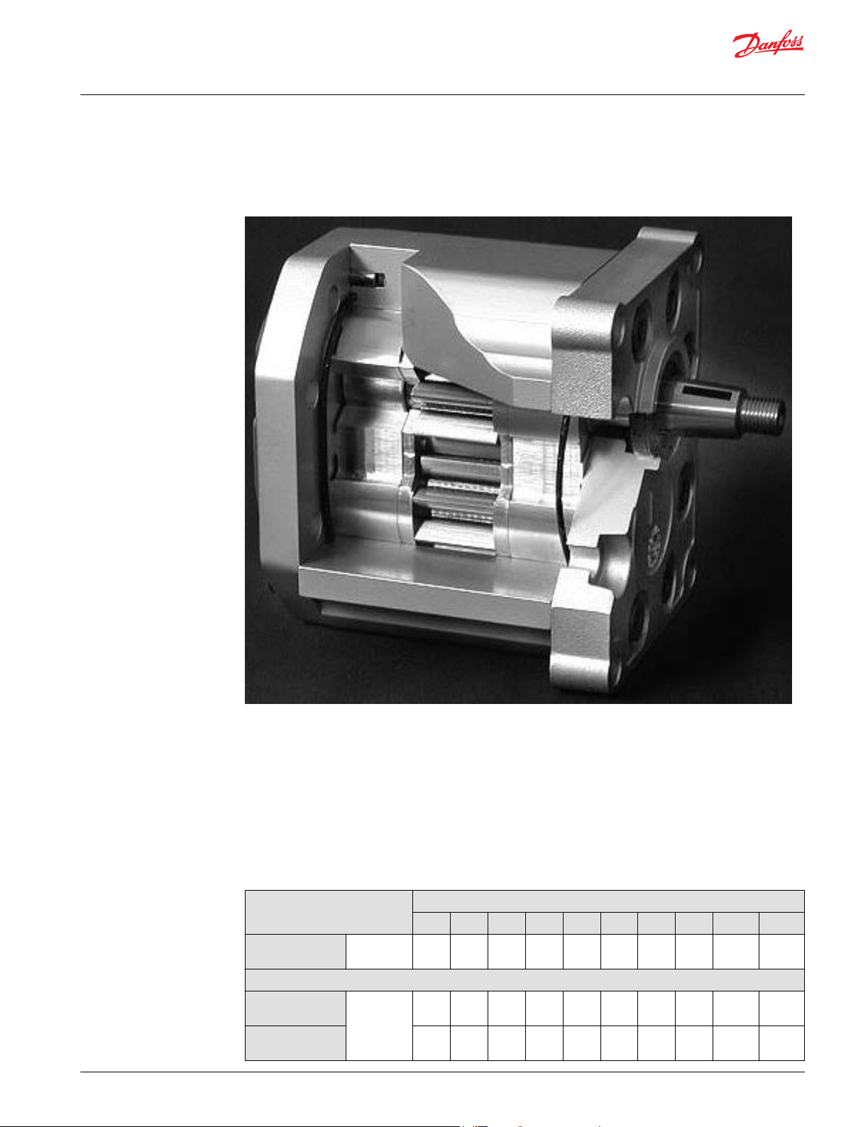
Technical Information
G
ear Motors Group 1, 2, and 3
Group 3 Gear motors
SNU3NN
SNU3NN is the Group 3 unidirectional motor available in the whole displacements range from 22 up to 90
cm3/rev [1.35 up to 5.38 in3/rev].
The SNU3NN motor construction is derived from the correspondent pump SNP3.
Configurations include European and SAE flanges and shafts (01BA, 01FA, 01DA, 02AA, 02FA, 02DB, 03BB,
03FB, 03DB, 06AA, 06SA, 07BC, 07GA, 07SA).
Technical data
This table details the technical data for Group 3 gear motors based on the model and displacement
configuration.
Technical data for Group 3 gear motors
Frame size
022 026 033 038 044 048 055 063 075 090
Displacement
SNU3NN (unidirectional)
Peak pressure
Rated pressure
©
Danfoss | July 2021 BC319483612502en-000102 | 61
cm3/rev
[in3/rev]
bar [psi] 270
22.1
[1.35]
[3915]
250
[3625]
26.2
[1.60]
270
[3915]
250
[3625]
33.1
[2.02]
270
[3915]
250
[3625]
37.9
[2.32]
270
[3915]
250
[3625]
44.1
[2.69]
270
[3915]
250
[3625]
48.3
[2.93]
250
[3625]
230
[3336]
55.2
[3.36]
230
[3336]
210
[3045]
63.4
[3.87]
210
[3045]
190
[2755]
74.4
[4.54]
190
[2755]
170
[2465]
88.2
[5.38]
170
[2465]
150
[2175]
Page 62

C
Technical Information
G
ear Motors Group 1, 2, and 3
Group 3 Gear motors
Technical data for Group 3 gear motors (continued)
Minimum speed
Maximum speed
SNM3NN (bidirectional) motor in parallel
Peak pressure
Rated pressure
Minimum speed
Maximum speed
SNM3NN (bidirectional) motor in series
Peak pressure
Rated pressure
Minimum speed
Maximum speed
All (SNU3NN, SNM3NN)
Weight
Moment of inertia
of rotating
components
Frame size
022 026 033 038 044 048 055 063 075 090
min-1 (rpm) 800 800 800 800 800 800 800 600 600 600
2500 2500 2500 2500 2300 2300 2300 2300 2100 2100
bar [psi] 270
min-1 (rpm) 800 800 800 800 800 800 800 800 800 800
bar [psi] 250
min-1 (rpm) 800 800 800 800 800 800 800 800 800 800
kg [lb]
x 10-6kg•m
[x 10-6 lb•ft2]
2
270
270
270
270
250
230
210
190
[3915]
[3915]
[3915]
[3915]
[3915]
[3625]
[3336]
[3045]
[2755]
250
250
250
250
250
230
210
190
170
[3625]
[3625]
[3625]
[3625]
[3625]
[3336]
[3045]
[2755]
[2465]
2500 2500 2500 2500 2300 2300 2300 2300 2100 2100
250
250
250
250
230
210
190
170
[3625]
[3625]
[3625]
[3625]
[3625]
[3336]
[3045]
[2755]
[2465]
250
250
250
250
250
230
210
190
170
[3625]
[3625]
[3625]
[3625]
[3625]
[3336]
[3045]
[2755]
[2465]
2500 2500 2500 2500 2300 2300 2200 2100 2100 2100
6.8
6.8
7.2
7.3
7.5
7.6
7.8
8.1
8.5
[15.0]
[15.0]
[15.8]
[16.1]
[16.5]
[16.8]
[17.3]
[17.9]
[18.7]
198
216
246
267.2
294.2
312.2
342.3
378.3
426.4
[4698]
[5126]
[5837]
[6341]
[6981]
[7408]
[8123]
[8977]
[10 118]
170
[2465]
150
[2175]
150
[2175]
150
[2175]
8.9
[19.6]
486.5
[11 545]
Model code
1 kg•m2 = 23.68 lb•ft
2
Caution
The rated and peak pressure mentioned are for motors with flanged ports only. When threaded ports are
required a derated performance has to be considered. To verify the compliance of a high pressure
application with a threaded ports pump apply to a Danfoss representative.
A Family
A B C D E F G H I J K L M N O
● ● ● ● ● ● /
SNU3NN
SNU3GN
SNM3NN
SNM3NL
SNM3GN
SNM3GL
SNM3DN
Gr3 Unidirectional Motor
Gr3 Unidirectional Motor+Anticav.Check Valve
Gr3 Bidirectional Motor - Axial drain on cover
Gr3 Bidirectional Motor-Vert.drain on rear cover
Gr3 Bidirectional Motor-Anticav.Check Valve - Axial drain on cover
Gr3 Bidirectional Motor-Anticav.Check Valve - Vert.drain on rear cover
Gr3 Bidirectional Motor-Internal drain valve
62 | © Danfoss | July 2021 BC319483612502en-000102
Page 63

Technical Information
G
ear Motors Group 1, 2, and 3
Group 3 Gear motors
B Displacement
A B C D E F G H I J K L M N O
● ● ● /
022
026
033
038
044
048
055
063
075
090
22,1 cc
26,2 cc
33,1 cc
37,9 cc
44,1 cc
48,3 cc
55,2 cc
63,4 cc
74,4 cc
88,2 cc
C Rotation
A B C D E F G H I J K L M N O
● /
L
R
B
Left (Counterclockwise)
Right (Clockwise)
Bidirectional
D Project version (value representing a change to the initial project)
A B C D E F G H I J K L M N O
● /
N
Std Version of Project
E Mounting flange
A B C D E F G H I J K L M N O
● ● /
Code Description(Type of flange • Type of drive gear • Preferred ports for configuration)
01
02
03
06
07
08
09
91
Pilot Ø50,8+4 holes (98,4x128,1)
Pilot Ø50,8+4 holes (98,4x137)
Pilot Ø60,3+4 holes (114,3x149,5)
Pilot Ø105+4 holes (102,0x145,0)
SAE B-pilot Ø101,6 -2 holes
SAE C-pilot Ø127 -4 holes
SAE A-pilot Ø82,55 -2 holes
Outrigger bearing typo 01 -Taper 1:8 M14x1,5 key 4x7,5
©
Danfoss | July 2021 BC319483612502en-000102 | 63
Page 64

Technical Information
G
ear Motors Group 1, 2, and 3
Group 3 Gear motors
Code Description(Type of flange • Type of drive gear • Preferred ports for configuration)
9Y
D7
F Drive Gear
Outrigger bearing type 07 -taper shaft 1:8-5/8-18UNF- Key6,375 with Dust Cover
Pilot Ø101,6+2 holes - for double shaft seal - Special 07
A B C D E F G H I J K L M N O
● ● /
AA
BA
BB
BC
BP
DA
DD
FA
FB
GA
GB
SA
SB
RA
SH
G Rear Cover
A B C D E F G H I J K L M N O
Taper 1:5-M16x1,5-Key 5
Taper 1:8-M14x1,5-Key 4
Taper 1:8-M16x1,5-Key 4,79
Taper 1:8-5/8-18UNF-2A-Key 6,375
Taper 1:8-5/8-18UNF-2A-Key 6,375 with NUT & WASHER (for flange 07)
DIN5482 B22x19 L=24 (for flange type 01)
DIN 5482 B28x25 L28 (for flange type 06)
ParallelØ20-Key 5x5 L30 (for flange type 01-02)
Parallel Ø22-Key 5x5 L40 (for flange type 03)
Parallel Ø22,225 x L25,4-Key 6,375x6,375 L25,4
ParallelØ22,225xL25,4-Key 6,375x6,375x25,4+thd hole:1/4-20UNC-2B
SAE J498-13T-16/32-SAE B
SAEJ498-13T-16/32-SAE A (for flange type 09)
SAEJ498-14T-12/24-SAE C- 4 bolt (for flange type 08)
SAE J498-15T-16/32 (for flange type 07)
● ● /
P1
M1
M2
M6
MF
L1
L2
L6
LT
D1
Std cover for unidirectional motors
Std cover motor axial drain on cover M14x1,5
Std cover motor axial drain on cover M12x1,5 ISO6149
Std cover motor axial drain on cover 9/16-18UNF-2B
Std cover motor axial drain on cover drain 3/8 Gas
Cover motor with radial drain on cover - Vertical M14x1,5
Cover motor with radial drain on cover - Horizontal M14x1,5
Cover motor with radial drain on cover - Vertical 9/16-18UNF-2B
Cover motor with radial drain on cover - Vertical 9/16-18UNF-2B drain up
Cover motor without drain (internal drained) - for SNM3DN series
H Inlet size; I Outlet size
A B C D E F G H I J K L M N O
● ● ● ● /
64 | © Danfoss | July 2021 BC319483612502en-000102
Page 65

Technical Information
G
ear Motors Group 1, 2, and 3
Group 3 Gear motors
A2
A3 25x26,19x52,37x3/8-16UNC
A4 31x30,18x58,72x7/16-14UNC
A5 37,5/27x35,71x69,85x1/2-13UNC
B7 20x40xM6
BA 18x55xM8
BB 27x55xM8
BC
C3 13,5x30xM6
C7 20x40xM8
CA 27x51xM10
CD 36x62xM10
E5 7/8-14UNF
E6 1-1/16-12UN
E8 1-5/16-12UN
E9 1-5/8-12UN
EA 1-7/8-12UN
H8 M27x2-ISO6149
H9 M33x2-ISO6149
F5 BSP 3/4 GAS
F6 BSP 1 GAS
F7
18,5x22,23x47,63x3/816UNC
36x55xM8
BSP 1-1/4 GAS
M5
M6
M7
MG
MH
MN
MR
25x52,37x26,19xM10
31x30,18x58,72xM10
37,5x35,71x69,85xM12
25/20x52,37x26,19xM10(=) - Special
31x30,18x58,72xM10 deep18 (=)
31x30,18x58,72xM10 deep12 (=)
37,5x35,71x69,85xM12 deep20 (=)
J Ports pos & Spec body
A B C D E F G H I J K L M N O
● ● /
NN
*
PL
©
Danfoss | July 2021 BC319483612502en-000102 | 65
Std from catalog
Inlet port Left position looking gear drive from front flange
Page 66

Technical Information
G
ear Motors Group 1, 2, and 3
Group 3 Gear motors
PR*
ZZ
*
to be used if inlet-outlet are different
Inlet port Right position looking gear drive from front flange
Port Bx-Bx in the center of the body
K Seals
A B C D E F G H I J K L M N O
N
B
D
X
Y
Z
Standard NBR seals
VITON seals
NBR seals + VITON shaft seal with dust lip
NBR seals + Dust Cover
VITON seals + Dust Cover
VITON shaft seal + Dust Cover
L Screws
A B C D E F G H I J K L M N O
N
B
Std burnished screws
Geomet screws - Anticorrosion screws
● /
● /
M Set valves
A B C D E F G H I J K L M N O
NNN
No valve
N Type of mark
A B C D E F G H I J K L M N O
N
A
Z
Standard Danfoss Marking
Standard Danfoss Marking+Customer Code-Special
Without Marking
O Mark position
A B C D E F G H I J K L M N O
N
A
Std Marking position (on top)
Special Marking position on the bottom
/ ● ● ●
/ ●
/ ●
66 | © Danfoss | July 2021 BC319483612502en-000102
Page 67

Technical Information
G
ear Motors Group 1, 2, and 3
Group 3 Gear motors
Motor performance graphs
The following graphs on the next pages provide typical inlet flow and output torque for Group 3 motors
at various working pressures. Data were taken using ISO VG46 petroleum /mineral based fluid at 50 °C
[122 °F] (viscosity = 28 mm2/s [132 SUS]).
©
Danfoss | July 2021 BC319483612502en-000102 | 67
Page 68

Technical Information
G
ear Motors Group 1, 2, and 3
Group 3 Gear motors
68 | © Danfoss | July 2021 BC319483612502en-000102
Page 69

Technical Information
G
ear Motors Group 1, 2, and 3
Group 3 Gear motors
©
Danfoss | July 2021 BC319483612502en-000102 | 69
Page 70

Technical Information
G
ear Motors Group 1, 2, and 3
Group 3 Gear motors
Flange, shaft, and port configurations
Motor Code Flange Shaft Port
SNM3
SNU3
01BA
pilot Ø 50.8 mm
[2.0 in]
European 01 4bolt
1:8 tapered
European
flanged port +
pattern
SNM3
SNU3
SNM3
SNU3
SNM3
SNU3
SNM3
SNU3
SNM3
SNU3
02BA
03BB
06AA
07BC
01FA
pilot Ø 50.8 mm
[2.0 in]
European 02 4bolt
pilot Ø 60.3 mm
[2.374 in]
European 03 4bolt
pilot Ø 105 mm
[4.133 in]
German 4-bolt
SAE B
pilot Ø 101.6 2bolt
pilot Ø 50.8 mm
[2.0 in]
European 01 4bolt
1:8 tapered
1:8 tapered
1:5 tapered
1:8 tapered
Ø 20 mm [0.787
in] parallel
European
flanged port +
pattern
European
flanged port +
pattern
German std
ports port X
pattern
Vertical four bolt
flanged port
European
flanged port +
pattern
SNM3
SNU3
SNM3
SNU3
SNM3
SNU3
SNM3
SNU3
02FA
03FB
07GA
01DA
pilot Ø 50.8 mm
[2.0 in]
European 02 4bolt
pilot Ø 60.3 mm
[2.374 in]
European 03 4bolt
SAE B
pilot Ø 101.6
mm 2-bolt
pilot Ø 50.8 mm
[2.0 in]
European 01 4bolt
Ø 20 mm [0.787
in] parallel
Ø 22 mm [0.866
in] parallel
Ø 22.225 mm
[0.875 in]
parallel
Splined shaft
13T – m 1.60
DIN 5482 – B22 x
19
European
flanged port +
pattern
European
flanged port +
pattern
Vertical four bolt
flanged port
European
flanged port +
pattern
70 | © Danfoss | July 2021 BC319483612502en-000102
Page 71

Technical Information
G
ear Motors Group 1, 2, and 3
Group 3 Gear motors
Motor Code Flange Shaft Port
SNM3
SNU3
06DD
pilot Ø 105 mm
[4.133 in]
German 4-bolt
Splined shaft
15T – m 1.60
DIN 5482 – B28 x
25
German std
ports port X
pattern
Shaft and flange availability
SNM3
SNU3
SNM3
SNU3
07SA
08RA pilot Ø 127mm
SAE B
pilot Ø 101.6
mm 2-bolt
[5.0 in] SAE C, 4bolt
Splined shaft
SAE J498 13T –
16/32DP
Splined shaft
SAE J498 14T 12/24DP
Vertical four bolt
flanged port
Vertical four bolt
flanged port
This table details the standard Group 3 shafts and flange combinations that are currently available with
the maximum shaft torque limits.
Shaft Mounting flange code with maximum torque in Nm [lb*in]
CodeDescription 01 02 03 06 07 08 09
Taper 1:5-M16x1,5-Key
AA
5
Taper 1:8-M14x1,5-Key
BA
4
Taper 1:8-M16x1,5-Key
BB
4,79
Taper
BC
1:8-5/8-18UNF-2A-Key
6,375
Taper
BP
1:8-5/8-18UNF-2A-Key
6,375 with NUT &
WASHER
(for flange 07)
DIN 5482 B22x19 L=24
DA
(for
flange type 01)
DIN 5482 B28x25 L28
DD
(for
flange type 06)
Parallel Ø20-Key 5x5
FA
L30 (for flange type
01-02)
Parallel Ø22-Key 5x5
FB
L40 (for flange type 03)
Parallel Ø22,225 x
GA
L25,4-Key 6,375x6,375
L25,4
350 [3097] 350 [3097]
500 [4425]
290 [2566] 290 [2566]
210 [1858] 210 [1858]
300 [2655]
300 [2655]
300 [2655]
300 [2655]
450 [3982]
230 [2035]
©
Danfoss | July 2021 BC319483612502en-000102 | 71
Page 72

g
CB
h
x
y
45o
A
a
c (4 holes min. full thd.
20 mm [0.787 in] deep)
i (4 holes min. full thd.
20 mm [0.787 in] deep)
z (4 holes min. full thd.
20 mm [0.787 in] deep)
b
v
D
FE
d
f
e
Technical Information
G
ear Motors Group 1, 2, and 3
Group 3 Gear motors
Shaft Mounting flange code with maximum torque in Nm [lb*in]
CodeDescription 01 02 03 06 07 08 09
GB
SA
SB
RA
SH
Parallel
Ø22,225xL25,4- Key
6,375x6,375x25,4+thd
hole:1/4-20UNC-2B
SAE J498-13T-16/32SAE B
SAE J498-13T-16/32SAE A
(for flange type 09)
SAE J498-14T-12/24SAE C-4
bolt (for flange type
08)
SAE J498-15T-16/32-
(for
flange type 07)
230 [2035]
270 [2389]
270 [2389]
400 [3540]
400 [3540]
Ports dimensions
Bidirectional motor ports
Available ports for Group 3 bidirectional motors
72 | © Danfoss | July 2021 BC319483612502en-000102
Page 73

g
B
h
45o
A
a
c (4 holes min.
full thd.
20 mm [0.787 in] deep)
i (4 holes min. full thd.
20 mm [0.787 in] deep)
b
v
Technical Information
G
ear Motors Group 1, 2, and 3
Group 3 Gear motors
Ports dimensions for bidirectional motors SNM3NN
Dimensions a b v c g h i x y z d e f
Frame
Port type A B C D E F
size
Drain
022
026
033
038
044
048
055
063
075
090
25.4
[1.0]
25.4
[1.0]
31.8
[1.251]
31.8
[1.251]
31.8
[1.251]
31.8
[1.251]
31.8
[1.251]
31.8
[1.251]
31.8
[1.251]
31.8
[1.251]
26.19
[1.031]
26.19
[1.031]
30.18
[1.188]
30.18
[1.188]
30.18
[1.188]
30.18
[1.188]
30.18
[1.188]
30.18
[1.188]
30.18
[1.188]
30.18
[1.188]
52.37
[2.061]
52.37
[2.061]
58.72
[2.311]
58.72
[2.311]
58.72
[2.311]
58.72
[2.311]
58.72
[2.311]
58.72
[2.311]
58.72
[2.311]
58.72
[2.311]
3/8–
16UNC–
2B
3/8–
16UNC–
2B
7/16–
14UNC–
2B
7/16–
14UNC–
2B
7/16–
14UNC–
2B
7/16–
14UNC–
2B
7/16–
14UNC–
2B
7/16–
14UNC–
2B
7/16–
14UNC–
2B
7/16–
14UNC–
2B
27
[1.063]55[2.165]
27
[1.063]55[2.165]
27
[1.063]55[2.165]
27
[1.063]55[2.165]
27
[1.063]55[2.165]
27
[1.063]55[2.165]
27
[1.063]55[2.165]
36
[1.417]55[2.165]
36
[1.417]55[2.165]
36
[1.417]55[2.165]
M14 x 1.5 9/16–18UNF–
M8
20
[0.79]40[1.58]
M8
20
[0.79]40[1.58]
M8
27
[1.063]51[2.008]
M8
27
[1.063]51[2.008]
M8
27
[1.063]51[2.008]
M8
27
[1.063]51[2.008]
M8
27
[1.063]51[2.008]
M8
36
[1.417]62[2.441]
M8
36
[1.417]62[2.441]
M8
36
[1.417]62[2.441]
M8 M26x1.5 15/16–
12UN–
2B
M8 M26x1.5 15/16–
12UN–
2B
M10 M33x2 15/8–
12UN–
2B
M10 M33x2 15/8–
12UN–
2B
M10 M33x2 15/8–
12UN–
2B
M10 M33x2 15/8–
12UN–
2B
M10 M33x2 15/8–
12UN–
2B
M10 M33x2 15/8–
12UN–
2B
M10 M33x2 15/8–
12UN–
2B
M10 M33x2 15/8–
12UN–
2B
¾ Gas
(BSPP)
¾ Gas
(BSPP)
1 Gas
(BSPP)
1 Gas
(BSPP)
1 Gas
(BSPP)
1 Gas
(BSPP)
1 Gas
(BSPP)
Gas
(BSPP)
Gas
(BSPP)
Gas
(BSPP)
2B
1¼
1¼
1¼
Unidirectional motor ports
Available ports for Group 3 unidirectional motors
©
Danfoss | July 2021 BC319483612502en-000102 | 73
Page 74

C
x
y
z (4 holes min. full thd.
20 mm [0.787 in] deep)
D
FE
d
f
e
Technical Information
G
ear Motors Group 1, 2, and 3
Group 3 Gear motors
Ports dimensions for unidirectional motors SNU3NN
Port type A B
Dimensions a b c v g h i
Frame size 022 Outlet
Inlet 20 [0.79]
026 Outlet 20 [0.79]
Inlet 20 [0.79]
033 Outlet 27 [1.063]
Inlet 20 [0.79]
038 Outlet 27 [1.063]
Inlet 20 [0.79]
044 Outlet 27 [1.063]
Inlet 27 [1.063]
048 Outlet 27 [1.063]
Inlet 27 [1.063]
055 Outlet 27 [1.063]
Inlet 27 [1.063]
063 Outlet 36 [1.417]
Inlet 27 [1.063]
075 Outlet 36 [1.417]
Inlet 27 [1.063]
090 Outlet 36 [1.417]
Inlet 27 [1.063]
20 [0.79] 40 [1.58] M8 3/8–16UNC–2B 27 [1.063] 55 [2.165] M8
40 [1.58] M8 3/8–16UNC–2B 18 [0.709] 55 [2.165] M8
40 [1.58] M8 3/8–16UNC–2B 27 [1.063] 55 [2.165] M8
40 [1.58] M8 3/8–16UNC–2B 18 [0.709] 55 [2.165] M8
51 [2.008] M10 7/16–14UNC–2B 27 [1.063] 55 [2.165] M8
40 [1.58] M8 3/8–16UNC–2B 18 [0.709] 55 [2.165] M8
51 [2.008] M10 7/16–14UNC–2B 27 [1.063] 55 [2.165] M8
40 [1.58] M8 3/8–16UNC–2B 18 [0.709] 55 [2.165] M8
51 [2.008] M10 7/16–14UNC–2B 27 [1.063] 55 [2.165] M8
51 [2.008] M10 3/8–16UNC–2B 18 [0.709] 55 [2.165] M8
51 [2.008] M10 7/16–14UNC–2B 27 [1.063] 55 [2.165] M8
51 [2.008] M10 3/8–16UNC–2B 18 [0.709] 55 [2.165] M8
51 [2.008] M10 ½–13UNC–2B 27 [1.063] 55 [2.165] M8
51 [2.008] M10 7/16–14UNC–2B 18 [0.709] 55 [2.165] M8
62 [2.441] M10 ½–13UNC–2B 36 [1.417] 55 [2.165] M8
51 [2.008] M10 7/16–14UNC–2B 27 [1.063] 55 [2.165] M8
62 [2.441] M10 ½–13UNC–2B 36 [1.417] 55 [2.165] M8
51 [2.008] M10 7/16–14UNC–2B 27 [1.063] 55 [2.165] M8
62 [2.441] M10 ½–13UNC–2B 36 [1.417] 55 [2.165] M8
51 [2.008] M10 7/16–14UNC–2B 27 [1.063] 55 [2.165] M8
Unidirectional motor ports
Available ports for Group 3 unidirectional motors
74 | © Danfoss | July 2021 BC319483612502en-000102
Page 75

Technical Information
G
ear Motors Group 1, 2, and 3
Group 3 Gear motors
Ports dimensions for unidirectional motors SNU3NN
Port type C D E F
Dimensions x y z d e f
Frame size 022 Outlet
Inlet 20 [0.79]
026 Outlet 20 [0.79]
Inlet 20 [0.79]
033 Outlet 27 [1.063]
Inlet 20 [0.79]
038 Outlet 27 [1.063]
Inlet 20 [0.79]
044 Outlet 27 [1.063]
Inlet 27 [1.063]
048 Outlet 27 [1.063]
Inlet 27 [1.063]
055 Outlet 27 [1.063]
Inlet 27 [1.063]
063 Outlet 36 [1.417]
Inlet 27 [1.063]
075 Outlet 36 [1.417]
Inlet 27 [1.063]
090 Outlet 36 [1.417]
Inlet 27 [1.063]
20 [0.79] 40 [1.58] M8 M26 x 1.5 ¾ Gas (BSPP) 15/16–12UN–2B
40 [1.58] M8 M26 x 1.5 ¾ Gas (BSPP) 11/16–12UN–2B
40 [1.58] M8 M26 x 1.5 ¾ Gas (BSPP) 15/16–12UN–2B
40 [1.58] M8 M26 x 1.5 ¾ Gas (BSPP) 11/16–12UN–2B
51 [2.008] M10 M33x2 1 Gas (BSPP) 15/8–12UN–2B
40 [1.58] M8 M26 x 1.5 ¾ Gas (BSPP) 15/16–12UN–2B
51 [2.008] M10 M33x2 1 Gas (BSPP) 15/8–12UN–2B
40 [1.58] M8 M26 x 1.5 ¾ Gas (BSPP) 15/16–12UN–2B
51 [2.008] M10 M33 x 2 1 Gas (BSPP) 15/8–12UN–2B
51 [2.008] M10 M33 x 2 1 Gas (BSPP) 15/16–12UN–2B
51 [2.008] M10 M33 x 2 1 Gas (BSPP) 15/8–12UN–2B
51 [2.008] M10 M33 x 2 1 Gas (BSPP) 15/16–12UN–2B
51 [2.008] M10 M33 x 2 1 Gas (BSPP) 17/8–12UN–2B
51 [2.008] M10 M33 x 2 1 Gas (BSPP) 15/8–12UN–2B
62 [2.441] M10 M42 x 2 1¼ Gas (BSPP) 17/8–12UN–2B
51 [2.008] M10 M33 x 2 1 Gas (BSPP) 15/8–12UN–2B
62 [2.441] M10 M42 x 2 1¼ Gas (BSPP) 17/8–12UN–2B
51 [2.008] M10 M33 x 2 1 Gas (BSPP) 15/8–12UN–2B
62 [2.441] M10 M42 x 2 1¼ Gas (BSPP) 17/8–12UN–2B
51 [2.008] M10 M33 x 2 1 Gas (BSPP) 15/8–12UN–2B
Anti-cavitation check valve - SNM3GN
Danfoss offers an optional integral anti-cavitation check valve integrated in Group 3 motors bearing
blocks. Available for all the displacements, the valve directs internally the flow from the motor outlet to
the inlet, when the outlet pressure gets higher then the inlet one.
Valve schematic diagram
©
Danfoss | July 2021 BC319483612502en-000102 | 75
Page 76

46.5 [1.83]
34
[1.338]
46
[1.118]
6
[0.24]
40
[1.574]
24 [0.944]
5
[0.196]
20 [0.787]
24
[0.944]
14.5 [0.571]
8 [0.314]
22 [0.866]
5 [0.196]
±0.75 [±0.03]
121.5 [4.783] max
98.4 [3.874]
115 ±0.25 [4.527 ±0.010]
Ø 50.8
[2.0 ]
-0.030
-0.076
-0.001
-0.003
Ø 20 [0.787 ]
0
-0.021
0
-0.0008
Ø 22 [0.866]
M8 (full thd 12 [0.472] deep)
M10 (full thd 17 [0.669] deep)
E/e
C/c
B max
D/d
A
< 40: ±0.20 [0.008]
> 40: ±0.25 [0.010]
85.2 [3.354]
42.9 [1.689]
(128.1 [5.043])
(54.3 [2.137])
148 [ 5.826] max
(96.2 [3.787])
150.5 [5.925] max
M14x1.5-6g
22.22 ±0.50
[0.874 ±0.020]
44.44
±0.75
[1.749 ±0.03]
1:8
B - B
A - A
B
B
A
A
11.0-11.5 [0.433-0.453]
Spline:
B22x19 DIN 5482
(Profile offset -0.10 [0.024])
Ø0.75 [0.030] X
Distance from
front flange
to shoulder
Distance from
front flange
to shoulder
5 [0.196 ]
0
-0.030
0
-0.001
-0.008
22 [0.866 ]
+0.10
-0.20
+0.004
Ø 21.5
[0.846 ]
0
-0.130
0
-0.005
M8 (full thd 18 [0.708] deep)
[0.453 ]
+0.30
+0.010
-0.1
0
-0.004
4
0 0
-0.030
[0.158 ]
-0.001
11.5
X
M14x1.5-6H
Drain port
01BA01DA01FA
Nut and washer supplied with pump
Recommended tightening tor que: 75-85 Nm
mm
[in]
Technical Information
G
ear Motors Group 1, 2, and 3
Group 3 Gear motors
Anticavitation check valve cross section
Dimensions
SNM3NN, SNU3NN – 01FA, 01DA and 01BA
Standard porting drawing for01FA, 01DA and 01BA
76 | © Danfoss | July 2021 BC319483612502en-000102
Bidirectional motors dimensions – 01FA, 01DA and 01BA
Frame size 022 026 033 038 044 048 055 063 075 090
Dimension
A
B
63.0
[2.480]
132.5
[5.216]
64.5
[2.539]
135.5
[5.334]
67.0
[2.637]
140.5
[5.531]
68.8
[2.708
144.0
[5.669]
71.0
[2.795]
148.5
[5.846]
72.5
[2.854]
151.5
[5.964]
75.0
[2.952]
156.5
[6.161]
78.0
[3.070]
162.5
[6.397]
82.0
[3.228]
170.5
[6.712]
87.0
[3.425]
180.5
[7.106]
Page 77

46.5 [1.83]
34 [1.338]
46 [1.118]
6 [0.236]
40 [1.574]
24 [0.944]
5 [0.196]
20 [0.787]
24
[0.944]
14.5 [0.571]
8 [0.314]
22 [0.866]
5 [0.196]
±0.75 [±0.03]
115 ±0.25 [4.527 ±0.010]
Ø 50.8
[2.0 ]
-0.030
-0.076
-0.001
-0.003
Ø 20 [0.787 ]
0
-0.021
0
-0.0008
Ø 22 [0.866]
M8 (full thd 12 [0.472] deep)
M10 (full thd 17 [0.669] deep)
E/e
C/c
B max
D/d
A
< 40: ±0.20 [0.008]
> 40: ±0.25 [0.010]
148 [ 5.826] max
M14x1.5-6g
22.22 ±0.50
[0.874 ±0.02]
1:8
B - B
A - A
B
B
A
A
11.0-11.5 [0.433-0.453]
Spline:
B22x19 DIN 5482
(Profile offset -0.10 [0.024])
Ø0.75 [0.030] X
Distance from
front flange
to shoulder
Distance from
front flange
to shoulder
5 [0.196 ]
0
-0.030
0
-0.001
-0.008
22 [0.866 ]
+0.10
-0.20
+0.004
Ø 21.5
[0.846 ]
0
-0.130
0
-0.005
M8 (full thd 18 [0.708] deep)
[0.453 ]
+0.30
+0.010
-0.10
-0.004
4
0 0
-0.030
[0.158 ]
-0.001
11.5
X
body width
124.5 [4.9] max
98.4 [3.87]
58 [2.28] max
105 [4.13] max
163 [6.42] max
(137 [5.39])
92 [3.62] 45 [1.77]
44.44 ±0.75 [1.749 ±0.03]
M14x1.5-6H
Drain port
02BA
02DA
02FA
Nut and washer supplied with pump
Recommended tightening tor que: 75-85 Nm
mm
[in]
Technical Information
G
ear Motors Group 1, 2, and 3
Group 3 Gear motors
Bidirectional motors dimensions – 01FA, 01DA and 01BA (continued)
Frame size 022 026 033 038 044 048 055 063 075 090
Inlet/Outlet
For unidirectional motors dimensions see Ports dimensions on page 72.
For unidirectional motors no case drain hole into the rear cover.
Model code examples and maximum shaft torque
Flange/drive gear Model code example Maximum shaft torque
01FA SNM3NN/075BN01FAM1CACANNNN/NNNNN 210 N•m [1858 lb•in]
01DA SNM3NN/026BN01DAM1C7C7NNNN/NNNNN 290 N•m [2566 lb•in]
01BA SNM3NN/044BN01BAM1CACANNNN/NNNNN 350 N•m [3097 lb•in]
For further details on ordering, see Model code on page 62.
C/c 20 [0.79] 27 [1.063]
D/d 40 [1.58] 51 [2.007]
E/e M8 M10
SNM3NN, SNU3NN – 02FA, 02DB and 02AA
Standard porting drawing for 02FA, 02DB and 02AA
71.0
[2.795]
148.5
[5.846]
72.5
[2.854]
151.5
[5.964]
75.0
[2.952]
156.5
[6.161]
78.0
[3.070]
162.5
[6.397]
©
Danfoss | July 2021 BC319483612502en-000102 | 77
Bidirectional motors dimensions – 02FA, 02DA and 02BA
Frame size 022 026 033 038 044 048 055 063 075 090
Dimension
Inlet/Outlet
For unidirectional motors dimensions Ports dimensions on page 72.
For unidirectional motors no case drain hole into the rear cover.
A
63.0
[2.480]
B
132.5
[5.216]
64.5
[2.539]
135.5
[5.334]
C/c 20 [0.79] 27 [1.063]
D/d 40 [1.58] 51 [2.007]
E/e M8 M10
67.0
[2.637]
140.5
[5.531]
68.8
[2.708
144.0
[5.669]
82.0
[3.228]
170.5
[6.712]
87.0
[3.425]
180.5
[7.106]
Page 78

X
body width
Distance from front flange
to cone reference diameter
-0.030
-0.076
-0.012
-0.003
A
D/d ±0.25 [±0.010]
B max
22.22 ±0.50 [0.875±0.020 ]
Ø60.3 [2.374 ]
115 ±0.25[4.527 ±0.010]
E/e
C/c
Ø 25 [0.984]
M16x1.5-6g
22 [0.866]
60 [2.362]
146.5 [5.768] max
114.3 [4.5]
9 [0.354]
50 [1.968]
59 [2.323]
28.5 [1.122]
28
[1.102]
14.5 [0.571]
17.5 [0.689]
1:8
M10 (full thd 17 [0.669] deep)
±0.75 [±0.030]
8 [0.315]
B-B
B
B
148 [ 5.826] max
(149.5 [ 5.885])
100 [ 3.937]
49.5
[ 1.949]
116 [4.566] max
65.5 [2.578] max
181.5 [ 7.145] max
4.79
[0.189 ]
0
-0.30
0
-0.012
-0.010
13.5 [0.532 ]
+0.15
-0.25
+0.006
Ø 22 [0.866 ]
0
-0.021
0
-0.0008
A - A
A
A
Distance from
front flange
to shoulder
5 [0.196 ]
0
-0.030
0
-0.001
-0.008
24 [0.945 ]
+0.10
-0.20
+0.004
M8 (full thd 18 [0.708] deep)
To rque for nut: 95-105 Nm
11.0-11.5 [0.433-0.453]
Ø0.75 [0.030] X
44.44 ±0.75 [1.749 ±0.03]
M14x1.5-6H
Drain port
03BB03FB
mm
[in]
Technical Information
G
ear Motors Group 1, 2, and 3
Group 3 Gear motors
Model code examples and maximum shaft torque
Flange/drive gear Model code example Maximum shaft torque
02FA SNM3NN/044BN02FAM1CACANNNN/NNNNN 210 N•m [1858 lb•in]
02DA SNM3NN/033BN02DAM1CACANNNN/NNNNN 290 N•m [2566 lb•in]
02BA SNM3NN/026BN02BAM1C7C7NNNN/NNNNN 350 N•m [3097 lb•in]
For further details on ordering, see Model code on page 62.
SNM3NN, SNU3NN – 03FB and 03BB
Standard porting drawing for 03FB and 03BB
Bidirectional motors dimensions – 03FB and 03BB
Frame size 022 026 033 038 044 048 055 063 075 090
Dimension
78 | © Danfoss | July 2021 BC319483612502en-000102
Inlet/Outlet
For unidirectional motors dimensions, see Ports dimensions on page 72.
For unidirectional motors no case drain hole into the rear cover.
A
61
[2.4]63[2.48]
B
132.5
[5.22]
C/c 18 [0.71] 27 [1.063]
D/d 55 [2.16]
135.5
[5.33]
E/e M8
64.5
[2.54]
140.5
[5.53]
66.5
[2.62]
144.0
[5.67]
69.5
[2.74]
148.5
[5.85]
72.5
[2.854]75[2.95]78[3.07]82[3.23]87[3.43]
151.5
[5.96]
156.5
[6.16]
162.5
[6.4]
170.5
[6.71]
180.5
[7.11]
Page 79

11.0-11.5 [0.433-0.453]
Ø0.75 [0.030] X
40 [1.574]
1:5
45
o
28 [1.102]
8 [0.314]
22 [0.866]
25
[0.984]
51 [2.007]
23.5 [0.925]
15 [0.590] 11 [0.433]
7 [0.275]
±0.75 [±0.03]
M8 (full thd 12 [0.472] deep)
E/e
C/c
B max
D/d
A
A - A
A
A
Spline:
B28x25 DIN 5482
(Profile offset: 0.202 [0.008])
Distance from front
flange to shoulder
5 [0.196 ]
0
-0.030
0
-0.001
Ø 27.5
[1.082 ]
0
-0.130
0
-0.005
[0.512 ]
+0.30
+0.010
-0.1
0
-0.0
04
13.0
123.5 [4.862] max
102.0 [4.015]
115 ±0.25 [4.527 ±0.010]
±0.25 [0.010]
22.22 ±0.50
[0.874 ±0.020]
X
body width
-0.036
-0.090
-0.001
-0.003
Ø105 [4.133 ]
Ø
25 [0.984]
M16x1.5-6g
108 [4.251] max
58.5 [2.303] max
148 [ 5.826] max
166.5 [ 6.555] max
(145 [5.708])
97 [3.818]
48 [1.889]
44.44 ±0.75 [1.749 ±0.03]
M14x1.5-6H
Drain port
06DD 06AA
To rque for nut: 95-105 Nm
mm
[in]
Technical Information
G
ear Motors Group 1, 2, and 3
Group 3 Gear motors
Model code examples and maximum shaft torque
Flange/drive gear Model code example Maximum shaft torque
03FB SNM3NN/063BN03FBM1CACANNNN/NNNNN 300 N•m [2655 lb•in]
03BB SNM3NN/090BN03BBM1CACANNNN/NNNNN 500 N•m [4425 lb•in]
For further details on ordering, seeModel code on page 62.
SNM3NN, SNU3NN – 06AA
Standard porting drawing for 06AA
Bidirectional motors dimensions – 06DD AND 06AA
Frame size 022 026 033 038 044 048 055 063 075 090
A
63.0
[2.480]
B
132.5
[5.216]
C/c 20 [0.79] 27 [1.063]
©
Danfoss | July 2021 BC319483612502en-000102 | 79
D/d 40 [1.58] 51 [2.007]
E/e M8 M10
For unidirectional motors dimensions, see Ports dimensions on page 72.
For unidirectional motors no case drain hole into the rear cover.
Model code examples and maximum shaft torque
Flange/drive gear Model code example Maximum shaft torque
06DD SNM3NN/044BN06DDM1BBBBNNNN/NNNNN 300 N•m [2655 lb•in]
06AA SNM3NN/022BN06AAM1BABANNNN/NNNNN 450 N•m [3982 lb•in]
For further details on ordering, see Model code on page 62.
64.5
[2.539]
135.5
[5.334]
67.0
[2.637]
140.5
[5.531]
68.8
[2.708
144.0
[5.669]
71.0
[2.795]
148.5
[5.846]
72.5
[2.854]
151.5
[5.964]
75.0
[2.952]
156.5
[6.161]
78.0
[3.070]
162.5
[6.397]
82.0
[3.228]
170.5
[6.712]
87.0
[3.425]
180.5
[7.106]
Page 80

±0.75 [±0.03]
(full thd 20 [0.787] deep)
F/f
B max
D/d
A
6.375 [0.250 ]
0
-0.025
0 0
-1.5 [0.059]
0
-0.001
115 ±0.25 [4.527 ±0.01]
±0.25 [0.01]
C/c
E/e
±0.25 [0.010]
22.22 ±0.50 [0.874 ±0.020]
body width
0
-0.127
0
-0.005
Ø21.806 [0.858 ]
176.5 [6.948] max
R 61 [2.402] max
146.05 [5.75]
41.2 [7.622]
41.2 [7.622]
33.3 [1.311]
33.3 [1.311]
25.0 [0.984]
7.9 [0.311]
7.9 [0.311]
7.9 [0.311]
13.5 [0.531]
9.5 [0.374]
157 [ 6.181] max
14.15-14.75 [0.557-0.580]
6.35-5.25 [0.25-0.206]
24.76-25.07 [0.974-0.987]
Ø0.75 [0.03]
X
Ø 22.225
[0.875 ]
0
-0.025
0
-0.001
Ø 101.6
[4.0 ]
0
-0.05
0
-0.002
X
A
A
B
B
A-A
6.375 [0.250 ]
0
-0.025
0
-0.001
3.33-3.07 [0.131-0.12]
B-B
Splined:
SAE J498-13T-16/32DP
Flat root side fit
(circular tooth thick ness
0.127 [0.005] less than
standard class 1 fit)
9/16-18UNF-2B
Drain port
5/8-18UNF-2A
28.4 [1.118]
59.4 [2.338]
42.9 [1.689]
23.1 [0.909]
Ø 22.225 [0.875]
Cone reference diameter
Distance from
front flange
to shoulder
Distance from
front flange
to shoulder
Ø 4 ±0.1[0.157±0.004 ]
44.44 ±0.75 [1.749
±0.03
]
07GA07SA07BC
1:8
mm
[in]
Technical Information
G
ear Motors Group 1, 2, and 3
Group 3 Gear motors
SNM3NN, SNU3NN – 07BC, 07SA and 07GA
Standard porting drawing for 07BC, 07SA and 07GA
Bidirectional motors dimensions – 07BC, 07SA and 07GA
Frame size 022 026 033 038 044 048 055 063 075 090
Dimension
Inlet/Outlet
A
63.0
[2.480]
B
132.5
[5.216]
64.5
[2.539]
135.5
[5.334]
67.0
[2.637]
140.5
[5.531]
C/c 25.4 [1] 31.8 [1.251]
68.8
[2.708
144.0
[5.669]
71.0
[2.795]
148.5
[5.846]
72.5
[2.854]
151.5
[5.964]
75.0
[2.952]
156.5
[6.161]
78.0
[3.070]
162.5
[6.397]
D/d 26.19 [1.031] 30.18 [1.188]
E/e 52.37 [2.061] 58.72 [2.311]
F/f 3/8–16UNC–2B 7/16–14UNC–2B
For unidirectional motors dimensions, see Ports dimensions on page 72.
For unidirectional motors no case drain hole into the rear cover.
Model code examples and maximum shaft torque
Flange/drive gear Model code example Maximum shaft torque
07BC SNM3NN/026BN07BCM6A3A3NNNN/NNNNN 300 N•m [2655 lb•in]
07SA SNM3NN/063BN07SAM6A4A4NNNN/NNNNN 270 N•m [2389 lb•in]
07GA SNM3NN/090BN07GAM6A4A4NNNN/NNNNN 230 N•m [2035 lb•in]
For further details on ordering, see Model code on page 62.
80 | © Danfoss | July 2021 BC319483612502en-000102
82.0
[3.228]
170.5
[6.712]
87.0
[3.425]
180.5
[7.106]
Page 81

Danfoss
Power Solutions GmbH & Co. OHG
Krokamp 35
D-24539 Neumünster, Germany
Phone: +49 4321 871 0
Danfoss
Power Solutions ApS
Nordborgvej 81
DK-6430 Nordborg, Denmark
Phone: +45 7488 2222
Danfoss
Power Solutions (US) Company
2800 East 13th Street
Ames, IA 50010, USA
Phone: +1 515 239 6000
Danfoss
Power Solutions Trading
(Shanghai) Co., Ltd.
Building #22, No. 1000 Jin Hai Rd
Jin Qiao, Pudong New District
Shanghai, China 201206
Phone: +86 21 2080 6201
Products we offer:
Hydro-Gear
www.hydro-gear.com
Daikin-Sauer-Danfoss
www.daikin-sauer-danfoss.com
Cartridge valves
•
DCV directional control
•
valves
Electric converters
•
Electric machines
•
Electric motors
•
Gear motors
•
Gear pumps
•
Hydraulic integrated
•
circuits (HICs)
Hydrostatic motors
•
Hydrostatic pumps
•
Orbital motors
•
PLUS+1® controllers
•
PLUS+1® displays
•
PLUS+1® joysticks and
•
pedals
PLUS+1® operator
•
interfaces
PLUS+1® sensors
•
PLUS+1® software
•
PLUS+1® software services,
•
support and training
Position controls and
•
sensors
PVG proportional valves
•
Steering components and
•
systems
Telematics
•
Danfoss Power Solutions is a global manufacturer and supplier of high-quality hydraulic and
electric components. We specialize in providing state-of-the-art technology and solutions
that excel in the harsh operating conditions of the mobile off-highway market as well as the
marine sector. Building on our extensive applications expertise, we work closely with you to
ensure exceptional performance for a broad range of applications. We help you and other
customers around the world speed up system development, reduce costs and bring vehicles
and vessels to market faster.
Danfoss Power Solutions – your strongest partner in mobile hydraulics and mobile
electrification.
Go to www.danfoss.com for further product information.
We offer you expert worldwide support for ensuring the best possible solutions for
outstanding performance. And with an extensive network of Global Service Partners, we also
provide you with comprehensive global service for all of our components.
Local address:
Danfoss can accept no responsibility for possible errors in catalogues, brochures and other printed material. Danfoss reserves the right to alter its products without notice. This also applies to products
already on order provided that such alterations can be made without subsequent changes being necessary in specifications already agreed.
All trademarks in this material are property of the respective companies. Danfoss and the Danfoss logotype are trademarks of Danfoss A/S. All rights reserved.
©
Danfoss | July 2021 BC319483612502en-000102
 Loading...